US8313264B2 - Flanged member and a flange joint comprising flange members - Google Patents
Flanged member and a flange joint comprising flange members Download PDFInfo
- Publication number
- US8313264B2 US8313264B2 US10/500,583 US50058304A US8313264B2 US 8313264 B2 US8313264 B2 US 8313264B2 US 50058304 A US50058304 A US 50058304A US 8313264 B2 US8313264 B2 US 8313264B2
- Authority
- US
- United States
- Prior art keywords
- flanged
- flanged member
- load transferring
- radial direction
- abutment point
- Prior art date
- Legal status (The legal status is an assumption and is not a legal conclusion. Google has not performed a legal analysis and makes no representation as to the accuracy of the status listed.)
- Expired - Lifetime
Links
- 230000007704 transition Effects 0.000 claims description 5
- 238000009434 installation Methods 0.000 abstract description 2
- 238000007789 sealing Methods 0.000 description 9
- 239000002184 metal Substances 0.000 description 7
- 239000000463 material Substances 0.000 description 6
- 238000007796 conventional method Methods 0.000 description 3
- 238000004519 manufacturing process Methods 0.000 description 3
- 239000012530 fluid Substances 0.000 description 2
- 238000005304 joining Methods 0.000 description 2
- 238000000034 method Methods 0.000 description 2
- 238000012546 transfer Methods 0.000 description 2
- 230000015556 catabolic process Effects 0.000 description 1
- 230000007797 corrosion Effects 0.000 description 1
- 238000005260 corrosion Methods 0.000 description 1
- 230000000694 effects Effects 0.000 description 1
- 230000007613 environmental effect Effects 0.000 description 1
- 238000012423 maintenance Methods 0.000 description 1
- 238000012360 testing method Methods 0.000 description 1
- 238000003466 welding Methods 0.000 description 1
Images


Classifications
-
- F—MECHANICAL ENGINEERING; LIGHTING; HEATING; WEAPONS; BLASTING
- F16—ENGINEERING ELEMENTS AND UNITS; GENERAL MEASURES FOR PRODUCING AND MAINTAINING EFFECTIVE FUNCTIONING OF MACHINES OR INSTALLATIONS; THERMAL INSULATION IN GENERAL
- F16L—PIPES; JOINTS OR FITTINGS FOR PIPES; SUPPORTS FOR PIPES, CABLES OR PROTECTIVE TUBING; MEANS FOR THERMAL INSULATION IN GENERAL
- F16L23/00—Flanged joints
- F16L23/02—Flanged joints the flanges being connected by members tensioned axially
- F16L23/032—Flanged joints the flanges being connected by members tensioned axially characterised by the shape or composition of the flanges
-
- F—MECHANICAL ENGINEERING; LIGHTING; HEATING; WEAPONS; BLASTING
- F16—ENGINEERING ELEMENTS AND UNITS; GENERAL MEASURES FOR PRODUCING AND MAINTAINING EFFECTIVE FUNCTIONING OF MACHINES OR INSTALLATIONS; THERMAL INSULATION IN GENERAL
- F16B—DEVICES FOR FASTENING OR SECURING CONSTRUCTIONAL ELEMENTS OR MACHINE PARTS TOGETHER, e.g. NAILS, BOLTS, CIRCLIPS, CLAMPS, CLIPS OR WEDGES; JOINTS OR JOINTING
- F16B2200/00—Constructional details of connections not covered for in other groups of this subclass
- F16B2200/50—Flanged connections
- F16B2200/506—Flanged connections bolted or riveted
-
- Y—GENERAL TAGGING OF NEW TECHNOLOGICAL DEVELOPMENTS; GENERAL TAGGING OF CROSS-SECTIONAL TECHNOLOGIES SPANNING OVER SEVERAL SECTIONS OF THE IPC; TECHNICAL SUBJECTS COVERED BY FORMER USPC CROSS-REFERENCE ART COLLECTIONS [XRACs] AND DIGESTS
- Y10—TECHNICAL SUBJECTS COVERED BY FORMER USPC
- Y10T—TECHNICAL SUBJECTS COVERED BY FORMER US CLASSIFICATION
- Y10T403/00—Joints and connections
- Y10T403/36—Three or more serial joints, at least one diverse
- Y10T403/364—Separable intermediate joint
- Y10T403/366—Axially acting connector
Definitions
- the present invention relates to a flanged member intended to be included as a component in a pressure equipment device, as well as a joint comprising two joint halves in the form of two flanged members and included in a pressure equipment device.
- flanged member also called flange member or only flange
- flanged member is here intended not just a pipe member, one end of which has been provided with a ring-shaped collar or flange, but also different components which may be included in a pipe system and that have at least one flanged end. It may, for instance, pertain to valves, Y-pieces or joint parts which may have one or more flanged ends for connection to other parts in the pipe system, vessels having a flange for the mounting of a lid, halves of casings for axial flow turbines or the like.
- flanged member in this connection, also be regarded to comprise so-called blind flanges, i.e. an member that is used in order to close a pipe, by the fact that it is mounted on another flanged member in the pipe system or the like.
- a blind flange is frequently formed as a plate (without opening) that on one hand covers the pipe opening and on the other hand forms the flange, possibly with some type of an axially protruding portion.
- So-called flanged joints comprise two flanged members that are closely joined, usually by means of bolts that are screwed through the opposite flange of the two flanged members and with prestress against nuts. Also other types of joining devices may be used, e.g. clips or clamps.
- Flanged joints may generally be provided with sealing members or lack sealing members.
- Sealing members that transfer forces from a flange to another flange are usually denominated gaskets. Sealing members that do not transfer any significant forces from a flange to another and which enable metal-to-metal contact between the flanges are usually denominated seals.
- the present invention relates in particular to flanged joints without a gasket and which enable metal-to-metal contact, with or without a seal.
- Flanged joints and other joints where flanged members are included are used in numerous applications, and the dimensions of the pipes and members that are included may vary substantially. As examples of applications, may be mentioned within the offshore industry, sub sea industry, process industry, petrochemical industry, in power plants, in oil and gas transport pipes, on tankers, etc.
- the flanged joints and flanged members that are constructed according to conventional technique, with gaskets, and that are used here, are very heavy, space-demanding and expensive. It is given that reliability of the flanged joints as for function and in particular leak tightness has to be guaranteed, since breakdown may cause loss of human life as well as extensive environmental damage and production loss.
- a flanged joint having end surfaces that abut sealingly against each other after tightening of the bolts or the like of the joint, still starts to leak due to the fact that it is deformed when the system in which it is included is pressurised by the fact that a fluid begins to flow through the system. Said deformation depends foremost on the pressure in the pipe system, the properties of the material in the flange as well as the dimensions thereof.
- the object of the present invention is to provide a solution to the mentioned problems.
- a flanged member that is intended to be included as a component in a flanged joint, for installation in a pressure equipment device and having a first flanged end with a first end surface intended to be assembled together with a second end surface of a flanged end on another, second flanged member constituting a second component in said flanged joint.
- the first end surface is slightly concave in the radial direction over at least a part of the extension thereof in the radial direction.
- concave is meant that, at a cross-section through the flanged end, the end surface is limited by a curve being a concave function.
- the end surface is in other words slightly curved so that it curves or bulges inwards.
- the slightly concave or inwardly curving/hollow end surface will be somewhat deformed so that it becomes almost plane. In any case, it will not become convex and it will be possible to retain the highest surface pressure of the end surfaces farthest in at the opening of the flanged member, which is a condition for good leak tightness.
- the end surface is concave over the entire extension thereof in the radial direction.
- the concavity begins already farthest in at the opening of the flanged member.
- said first end surface is concave in the radial direction over essentially the area that, during use (i.e. pressurizing of the system where the member is included, see above), is foreseen to constitute contact surface against the corresponding end surface of said second flanged member.
- said first end surface comprises more than one concave part surface in the radial direction and said part surfaces may have different radii of curvature.
- the flanged member has an internal, through, axial opening and said first end surface has an innermost abutment point against the corresponding end surface of said second flanged member, which abutment point is situated farthest in the radial direction, at said opening, and that the concavity of the first end surface extends all the way in to said abutment point.
- the flanged member is characterized in that said first end surface has an innermost abutment point against the corresponding end surface of said second flanged member, which has an internal, through, axial opening, and that said innermost abutment point is situated farthest in the radial direction, at said opening, and that the concavity of the first end surface extends all the way in to said abutment point.
- the flanged member is characterized in that a conceived straight line X that connects the innermost point a of the first surface, in the radial direction, with the outermost point b thereof, in the radial direction, has a length Lx and that the concavity of the end surface has a maximum depth Dk in relation to a conceived plane surface produced by said line X, which depth Dk is of the order of 0.01%–2% of Lx.
- the depth Dk is of the order of 0.01%–0.2% of Lx.
- the mentioned interval of Dk is approximate since it also depends on the pressure in the pipe system, the properties of the material in the flange and the dimensions thereof in other respects.
- the joint that is proposed according to the present invention comprises two joint halves in the form of two flanged members included in a pressure equipment device, which members have at least one flanged end each having an end surface, and which members are put together via their end surfaces of said flanges, which surfaces are facing each other, characterized in that at least one of said flanged members, and preferably both, is designed according to the present invention.
- the advantage is obtained of a flanged member that in unloaded state is compensated for the deformation it is foreseen to be subject to when it is in a loaded state.
- you have a flanged joint that has sealing surfaces abutting against each other with metal to metal contact, all the way in to the fluid pressure, i.e. all the way in to the edge closest to the opening. Consequently, the joint is tight.
- FIG. 1 shows a schematic side view, in cross-section, of a joint according to the present invention
- FIG. 2 shows a schematic side view, in cross-section, of a part of a flanged member according to the present invention, and on an enlarged scale and
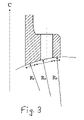
- FIG. 3 shows a flanged end with varying concavity or radius of curvature.
- the joint shown in FIG. 1 comprises two flanged members 1 , 2 , each having a first end 3 , 4 provided with a collar or flange 5 , 6 , as well as a second non-flanged end 7 , 8 .
- the flanged end 3 , 4 of the respective flanged members has an end surface 10 , 11 that in this case also is a contact surface, i.e. a surface intended to abut against a corresponding surface of the opposite flanged member, after assembly.
- the flanges 5 , 6 extend preferably 360° and are provided with through borings 13 , 14 . At joining, the flanges are bolted together to a joint by means of bolts that are inserted through said borings.
- a tubular duct 15 , 16 extends.
- the transition area 17 , 18 between the flange and the non-flanged end consists of an elliptically shaped area.
- the illustrated joint is a non-gasketed and seal-free joint.
- the end surfaces 10 , 11 of the flanged members facing each other are somewhat chamfered or inclined so that they, in radial cross-section, form an angle to each other, when they have been brought together but before assembly, so that the distance between the two end surfaces increases in the radial direction outwards, which is seen in FIG. 1 .
- a flanged member 1 included in the joint in FIG. 1 is shown schematically and in enlargement.
- the flanged member 1 has an end surface 10 having a concave shape in the radial direction.
- the concavity in the schematic illustration is strongly exaggerated, as is the chamfering/inclination of the end surface.
- the concavity is in effect very small and would, at a depiction according to scale of a flange having the illustrated proportions, not be seen at all. For this reason, here it has been necessary to strongly exaggerate the concavity of the shown end surface and also the inclination.
- the concavity of surface 10 in FIG. 2 i.e., the radius of curvature, is substantially constant.
- surface 10 may have a varying radius of curvature, as illustrated in FIG. 3 .
- R 1 , R 2 . . . R n need not be equal.
- the end surface 10 has an internal, through, axial opening 15 . It has an innermost abutment point a against the corresponding end surface of said second flanged member (not shown), which innermost abutment point is situated farthest in the radial direction, at said opening. It has also a corresponding outermost abutment point b against the corresponding end surface of said second flanged member, which outermost abutment point is situated farthest out in the radial direction. Said abutment points are connected with a conceived straight line X, having a length Lx.
- the concavity of the end surface has a maximum depth Dk in relation to a conceived plane surface produced by the same line X, which depth Dk is of the order of 0.01%–2% of Lx, and preferably 0.01%–0.2% of Lx.
- both of the flanged members in a joint have concave end surfaces, but it would also be feasible that only one of the members has a concave end surface.
- the concavity extends all over the end surface in the radial direction.
- the end surface should be concave in the radial direction over at least an area that essentially equals the area that will be subjected to a deforming force when the flanged member in question is assembled together with a second flanged member included in the joint, as well as during use.
- the present invention is not limited to the illustrated embodiment example but may be varied and modified in a variety of ways by a person skilled in the art; within the scope of the accompanying claims. Particularly, it should be pointed out that the invention is not limited to the illustrated embodiment example, but may, for instance, have a non-elliptical transition area, a non-inclined end surface, or be provided with seal, e.g. in the form of a seal ring in a groove.
- the end surface in the illustrated example is a concave surface having only one radius of curvature, but could also be a concave surface composed of a plurality of radii of curvature. It is of course also feasible to apply the invention to inwardly turned flanges, i.e. flanges that are turned inwards in the pipe system.
Landscapes
- Engineering & Computer Science (AREA)
- General Engineering & Computer Science (AREA)
- Mechanical Engineering (AREA)
- Flanged Joints, Insulating Joints, And Other Joints (AREA)
- Mutual Connection Of Rods And Tubes (AREA)
- Gasket Seals (AREA)
- Lining Or Joining Of Plastics Or The Like (AREA)
- Measuring Fluid Pressure (AREA)
- Storage Of Web-Like Or Filamentary Materials (AREA)
Applications Claiming Priority (4)
| Application Number | Priority Date | Filing Date | Title |
|---|---|---|---|
| SE0104467-6 | 2001-12-28 | ||
| SE0104467 | 2001-12-28 | ||
| SE0104467A SE524724C2 (sv) | 2001-12-28 | 2001-12-28 | Flänsförsett element försedd med en i radiell riktning konkav ändyta samt förband innefattande flänsförsedda element |
| PCT/SE2002/002448 WO2003062693A1 (fr) | 2001-12-28 | 2002-12-20 | Element bride comprenant une premiere extremite a bride presentant une surface terminale concave dans le sens radial, et joint a bride comprenant lesdits elements bride |
Publications (2)
| Publication Number | Publication Date |
|---|---|
| US20050129457A1 US20050129457A1 (en) | 2005-06-16 |
| US8313264B2 true US8313264B2 (en) | 2012-11-20 |
Family
ID=20286561
Family Applications (1)
| Application Number | Title | Priority Date | Filing Date |
|---|---|---|---|
| US10/500,583 Expired - Lifetime US8313264B2 (en) | 2001-12-28 | 2002-12-20 | Flanged member and a flange joint comprising flange members |
Country Status (10)
| Country | Link |
|---|---|
| US (1) | US8313264B2 (fr) |
| EP (1) | EP1472484B1 (fr) |
| AT (1) | ATE339644T1 (fr) |
| CA (1) | CA2471299A1 (fr) |
| DE (1) | DE60214775T2 (fr) |
| DK (1) | DK1472484T3 (fr) |
| ES (1) | ES2272806T3 (fr) |
| NO (1) | NO338101B1 (fr) |
| SE (1) | SE524724C2 (fr) |
| WO (1) | WO2003062693A1 (fr) |
Cited By (3)
| Publication number | Priority date | Publication date | Assignee | Title |
|---|---|---|---|---|
| US20130343902A1 (en) * | 2012-06-22 | 2013-12-26 | General Electric Company | Gas turbine conical flange bolted joint |
| US20170074063A1 (en) * | 2015-09-15 | 2017-03-16 | Cameron International Corporation | Marine Riser System |
| US20220010779A1 (en) * | 2018-11-02 | 2022-01-13 | Tp-Products As | A flange element, a flange connection comprising such flange elements and a tower structure |
Families Citing this family (7)
| Publication number | Priority date | Publication date | Assignee | Title |
|---|---|---|---|---|
| FR2891606B1 (fr) * | 2005-10-05 | 2009-03-06 | Snecma Sa | Dispositif de liaison a brides. |
| US8015882B2 (en) * | 2009-06-04 | 2011-09-13 | Rosemount Inc. | Industrial process control pressure transmitter and flange coupling |
| DE102011007388A1 (de) * | 2011-04-14 | 2012-10-18 | Siemens Aktiengesellschaft | Flansch, Anpassring, Anordnung mit einem Flansch oder Anpassring |
| AU2014235631B2 (en) | 2013-03-15 | 2017-08-24 | Ameriforge Group Inc. | Drilling riser assemblies |
| FI124788B (fi) * | 2013-05-03 | 2015-01-30 | Maricap Oy | Putkiliitos ja laippaosajärjestely putkiliitosta varten |
| US9829199B2 (en) * | 2014-10-30 | 2017-11-28 | Siemens Energy, Inc. | Flange with curved contact surface |
| US10627027B1 (en) | 2016-05-27 | 2020-04-21 | Brett Hutchinson | Method and apparatus for directing and containing leakage |
Citations (10)
| Publication number | Priority date | Publication date | Assignee | Title |
|---|---|---|---|---|
| US2739828A (en) * | 1949-12-06 | 1956-03-27 | Flexonics Corp | Pipe connector with flexible material joint |
| US2940779A (en) * | 1957-11-08 | 1960-06-14 | Taylor Forge & Pipe Works | Balanced face flange |
| US3135538A (en) * | 1959-05-18 | 1964-06-02 | Chemetron Corp | Flanged pipe joint having one flange deflectable |
| US4183562A (en) * | 1977-04-01 | 1980-01-15 | Regan Offshore International, Inc. | Marine riser conduit section coupling means |
| US5040714A (en) * | 1990-04-23 | 1991-08-20 | Vemco Corporation | Bore forming sealed coupling and process |
| US5050913A (en) * | 1989-01-09 | 1991-09-24 | Erwin Lenz | High pressure, rotatable pipe joints |
| US5230540A (en) * | 1989-03-15 | 1993-07-27 | Rolls-Royce Plc | Fluid-tight joint with inclined flange face |
| WO1993017268A1 (fr) | 1992-02-20 | 1993-09-02 | Steelproducts Offshore As | Accouplement pour tuyaux a brides, procede pour connecter les brides et utilisation de l'accouplement |
| US5851033A (en) * | 1997-04-30 | 1998-12-22 | Electric Power Research Institute, Inc. | Corrosion limiting device |
| US5938246A (en) * | 1997-02-10 | 1999-08-17 | Wallace; Thomas C. | Increased pressure fluid carrying pipeline system and method therefor |
-
2001
- 2001-12-28 SE SE0104467A patent/SE524724C2/sv not_active IP Right Cessation
-
2002
- 2002-12-20 AT AT02793743T patent/ATE339644T1/de not_active IP Right Cessation
- 2002-12-20 ES ES02793743T patent/ES2272806T3/es not_active Expired - Lifetime
- 2002-12-20 DK DK02793743T patent/DK1472484T3/da active
- 2002-12-20 WO PCT/SE2002/002448 patent/WO2003062693A1/fr active IP Right Grant
- 2002-12-20 CA CA002471299A patent/CA2471299A1/fr not_active Abandoned
- 2002-12-20 DE DE60214775T patent/DE60214775T2/de not_active Expired - Lifetime
- 2002-12-20 US US10/500,583 patent/US8313264B2/en not_active Expired - Lifetime
- 2002-12-20 EP EP02793743A patent/EP1472484B1/fr not_active Expired - Lifetime
-
2004
- 2004-07-21 NO NO20043137A patent/NO338101B1/no not_active IP Right Cessation
Patent Citations (10)
| Publication number | Priority date | Publication date | Assignee | Title |
|---|---|---|---|---|
| US2739828A (en) * | 1949-12-06 | 1956-03-27 | Flexonics Corp | Pipe connector with flexible material joint |
| US2940779A (en) * | 1957-11-08 | 1960-06-14 | Taylor Forge & Pipe Works | Balanced face flange |
| US3135538A (en) * | 1959-05-18 | 1964-06-02 | Chemetron Corp | Flanged pipe joint having one flange deflectable |
| US4183562A (en) * | 1977-04-01 | 1980-01-15 | Regan Offshore International, Inc. | Marine riser conduit section coupling means |
| US5050913A (en) * | 1989-01-09 | 1991-09-24 | Erwin Lenz | High pressure, rotatable pipe joints |
| US5230540A (en) * | 1989-03-15 | 1993-07-27 | Rolls-Royce Plc | Fluid-tight joint with inclined flange face |
| US5040714A (en) * | 1990-04-23 | 1991-08-20 | Vemco Corporation | Bore forming sealed coupling and process |
| WO1993017268A1 (fr) | 1992-02-20 | 1993-09-02 | Steelproducts Offshore As | Accouplement pour tuyaux a brides, procede pour connecter les brides et utilisation de l'accouplement |
| US5938246A (en) * | 1997-02-10 | 1999-08-17 | Wallace; Thomas C. | Increased pressure fluid carrying pipeline system and method therefor |
| US5851033A (en) * | 1997-04-30 | 1998-12-22 | Electric Power Research Institute, Inc. | Corrosion limiting device |
Cited By (6)
| Publication number | Priority date | Publication date | Assignee | Title |
|---|---|---|---|---|
| US20130343902A1 (en) * | 2012-06-22 | 2013-12-26 | General Electric Company | Gas turbine conical flange bolted joint |
| US9200520B2 (en) * | 2012-06-22 | 2015-12-01 | General Electric Company | Gas turbine conical flange bolted joint |
| US20170074063A1 (en) * | 2015-09-15 | 2017-03-16 | Cameron International Corporation | Marine Riser System |
| US9702213B2 (en) * | 2015-09-15 | 2017-07-11 | Cameron International Corporation | Marine riser system |
| US20220010779A1 (en) * | 2018-11-02 | 2022-01-13 | Tp-Products As | A flange element, a flange connection comprising such flange elements and a tower structure |
| US11873793B2 (en) * | 2018-11-02 | 2024-01-16 | Tp-Products As | Flange element, a flange connection comprising such flange elements and a tower structure |
Also Published As
| Publication number | Publication date |
|---|---|
| ATE339644T1 (de) | 2006-10-15 |
| ES2272806T3 (es) | 2007-05-01 |
| US20050129457A1 (en) | 2005-06-16 |
| DK1472484T3 (da) | 2007-01-15 |
| SE0104467L (sv) | 2003-06-29 |
| EP1472484B1 (fr) | 2006-09-13 |
| CA2471299A1 (fr) | 2003-07-31 |
| SE0104467D0 (sv) | 2001-12-28 |
| NO338101B1 (no) | 2016-08-01 |
| WO2003062693A8 (fr) | 2004-04-22 |
| WO2003062693A1 (fr) | 2003-07-31 |
| SE524724C2 (sv) | 2004-09-21 |
| NO20043137L (no) | 2004-07-21 |
| DE60214775T2 (de) | 2007-09-06 |
| DE60214775D1 (de) | 2006-10-26 |
| EP1472484A1 (fr) | 2004-11-03 |
Similar Documents
| Publication | Publication Date | Title |
|---|---|---|
| US5421623A (en) | Friction sealed coupling for pipe | |
| US6394507B1 (en) | Apparatus for connecting tubular bodies | |
| US7621567B2 (en) | Corrugated tube fitting with a ridge sealing device and method | |
| US7775561B2 (en) | Exhaust pipe joint with insert | |
| JP2019163857A (ja) | 管継手 | |
| US8313264B2 (en) | Flanged member and a flange joint comprising flange members | |
| US5845386A (en) | Method for connecting a multiple-piece elbow assembly | |
| US3628815A (en) | Conduit connection means | |
| US3917324A (en) | Pipe joint | |
| US10753521B1 (en) | Inner diameter seal gasket | |
| US10746330B2 (en) | Pipe coupling | |
| JP2868430B2 (ja) | 管材のフランジ接続構造 | |
| US20080018108A1 (en) | Hollowed, deformable, raised face bolt-ring | |
| US20060131883A1 (en) | Externally pressurized connection | |
| US4909548A (en) | Compound-taper flange assembly | |
| EP4127536B1 (fr) | Ensemble raccord | |
| RU2685626C1 (ru) | Фланцевое соединение для труб и аппаратов | |
| US20140361533A1 (en) | Pipe connector | |
| JPS6383488A (ja) | 管継手 | |
| RU57419U1 (ru) | Компактный фланец | |
| NO171613B (no) | Koblingssegment | |
| WO2012090171A2 (fr) | Joint d'étanchéité de rebord | |
| JPH0141875B2 (fr) | ||
| CA2182763A1 (fr) | Section de tuyau, particulierement les canalisations transportant des matieres abrasives ou corrosives |
Legal Events
| Date | Code | Title | Description |
|---|---|---|---|
| AS | Assignment |
Owner name: VERAX ENGINEERING AB, SWEDEN Free format text: ASSIGNMENT OF ASSIGNORS INTEREST;ASSIGNOR:WEBJORN, JAN;REEL/FRAME:016269/0266 Effective date: 20040625 |
|
| STCF | Information on status: patent grant |
Free format text: PATENTED CASE |
|
| FPAY | Fee payment |
Year of fee payment: 4 |
|
| MAFP | Maintenance fee payment |
Free format text: PAYMENT OF MAINTENANCE FEE, 8TH YR, SMALL ENTITY (ORIGINAL EVENT CODE: M2552); ENTITY STATUS OF PATENT OWNER: SMALL ENTITY Year of fee payment: 8 |