US83092A - Improvement in condensers - Google Patents
Improvement in condensers Download PDFInfo
- Publication number
- US83092A US83092A US83092DA US83092A US 83092 A US83092 A US 83092A US 83092D A US83092D A US 83092DA US 83092 A US83092 A US 83092A
- Authority
- US
- United States
- Prior art keywords
- condenser
- water
- pipe
- injection
- waste
- Prior art date
- Legal status (The legal status is an assumption and is not a legal conclusion. Google has not performed a legal analysis and makes no representation as to the accuracy of the status listed.)
- Expired - Lifetime
Links
Images

Classifications
-
- B—PERFORMING OPERATIONS; TRANSPORTING
- B01—PHYSICAL OR CHEMICAL PROCESSES OR APPARATUS IN GENERAL
- B01F—MIXING, e.g. DISSOLVING, EMULSIFYING OR DISPERSING
- B01F23/00—Mixing according to the phases to be mixed, e.g. dispersing or emulsifying
- B01F23/20—Mixing gases with liquids
- B01F23/23—Mixing gases with liquids by introducing gases into liquid media, e.g. for producing aerated liquids
-
- A—HUMAN NECESSITIES
- A62—LIFE-SAVING; FIRE-FIGHTING
- A62C—FIRE-FIGHTING
- A62C5/00—Making of fire-extinguishing materials immediately before use
- A62C5/02—Making of fire-extinguishing materials immediately before use of foam
Definitions
- the hijection-water by contact with which thel eX-haust steam is condensed, is necessarily admitted into the vacuous condensing-chamber, and the air-pump, which performs the duty of carrying off such injection-water, is therefore obliged to work against an atmospheric pressure upon'its piston corresponding to the vacuum obtained in said chamber, which amounts in common practice to from ten to twelve pounds to the square inch, and is a very serious detraction from the increased pressure on the engine-piston obtained by said vacuum.
- My invention relates to a cond ming-apparatus,- in which the condensing-vessel is arranged at the crown of a siphon, the length ofthe. longerleg of which is ⁇ in excess of that of a column of water which would be ⁇ sustained by the vacuum obtained in the condensingvessel, so that said long leg will constitute a wastepipe which will carry oii'the injection-water by its own gravity, as against the pressure of the atmosphere, while the shorter leg will constitute the injection-pipe in which atmospheric pressure will raise the water to a height corresponding to the degree of vacuum ob-v tained; from which itfollows that the power required tc'supply the condensing-water will be measured by the excess in the length of said leg over the height to which the water will articulate therein, as above stated.
- My invention consistsi First, inthe arrangement of several waste-pipes', of
- Figure II is a ground-plan oflsame.
- Figure III is a side elevation, taken at right angles to Fig. I.
- Figure IV is a plan View of condensing-vessel.
- Wliclr may be' constructed according to the common rules for injectioncondenser-s, as to form, size, and material, although a form which makes a horizontal section of equal or greater length and breadth than a vertical one is preferable.
- - rl d, d2' represent the waste-pipes connecting 'with the condenser at the bottom, and leading downward to the waste-well E and drain E.
- the pipe d may be of larger diameter, and project'up a few inches into lthe condenser, to act as an overiiow, to prevent the possiv bility of the condenser being Hooded with injection-4 water.
- F represents the exhaust-pipe leading ⁇ from the engine G to the condenser, into which it opens on the side opposite the'injection-pipe.
- H represents a pump of any approved construction, applied to the vinjection-pipe at any convenient point, in such manner as to raise the injection-water from the supply-well to the condenser.
- the pump will, on the start, require to raise the Water the full length ofthe injectie Y-pipe, but in proportion as the'vacuum becomes established in the condenser, atmospheric pressure will assist the pump, and decrease Ithe powerrequired-to operate the same.
- the length of the injection-pipe will be governed by, ghe elevation of the watersupply above 'the wasteram.
- the-length .ofthe injection-pipe will be equal to that of the wastepipes plus the height from the bottomrof the condenser 'to the iniectionriflce.
- the length of the waste-pipes will in practice be about thirty-four feet, and the additional length om one to three feet, so that under the most unfavorable'circumstances, the length' of the hijection-pipe will'noitexceed thirty-seven feet.
- the vacuum is not only maintained butperfected bythisfmeansi-- 3, L It may be here onse "ed, that'the relative position of the parts, except as to verticaldistanees, is of little importance, and may ⁇ be made to suit the ever-varying circumstances of loc ion. ,y v 'It is also manifest hatthe pump may be dispensed with when an equivalent natural command.
- Several inferio mddiiications of the apparatusv he made, as the application of a small air-pumpto exhaust the air from thecondenser in the first instance and carry oil such air' as may enter or leak therein during its operation.
- My apparatus may. further beused for the purpose of producing a vacn without acting as a condenser.
- I will now descxib .the fourth feature of my invention.
- the pipe I is provided with avalve or cock, I', by which the quantity of water passing through it may be regulated according to the demands of the boiler.
- I head of water is at I represents a small pipe, branching from the main f' This portion of i to feedtheboileiand the pipe J, leading from the l i
Landscapes
- Chemical & Material Sciences (AREA)
- Chemical Kinetics & Catalysis (AREA)
- Health & Medical Sciences (AREA)
- Public Health (AREA)
- Business, Economics & Management (AREA)
- Emergency Management (AREA)
- Heat Treatment Of Water, Waste Water Or Sewage (AREA)
Description
wetaaww il @fitta ai 'FRANKLIN' RANsoM, or BUFFALO, :JNW' ,YoRiljf Laim 12mm No. 83,092, daad caoba? 13, 1868, j l .4
MROVEMENT IN (.'ITZDENSERS.`
The Schedule referred to in these Letters Patent and making part 'of the same. 'H. I
To all whcmjit may concern.- Be it known that I, FRANKLIN RANsoM, of the city of Buffalo, in the county of Erie, and State. of New York, have inventedlra certain new and improved Condensing-Apparatus for Steam-Engines; and I do hereby declare that the following is a full, clear, and exact' description of the construction and operation thereof, reference being had to the accompanying drawings, making a part of this specification.l
The economy inthe working' of the steam-engine resulting from the use of the condenser, with its attendant air-pump, to produce a'nd maintain a vacuum,
into which .the exhaust steam may escape, is well understood; but the greatly-increased iirst cost of such condensing-engines, and their greater liability to derangement, and the higher order of skill required to manage them, have heretofore greatly restricted. their use.
Two classes of condenscrs are in common use, v iz, the
. l er the surface-condenser, and il is to the first-named class that my improvements relate. In the common construction of injection-condenser',
. the hijection-water, by contact with which thel eX-haust steam is condensed, is necessarily admitted into the vacuous condensing-chamber, and the air-pump, which performs the duty of carrying off such injection-water, is therefore obliged to work against an atmospheric pressure upon'its piston corresponding to the vacuum obtained in said chamber, which amounts in common practice to from ten to twelve pounds to the square inch, and is a very serious detraction from the increased pressure on the engine-piston obtained by said vacuum. It is a well-known fact in hydraulics that atmospheric pressure will raise and sustain a column of water in a pipe exhausted of air, thirty-three feet high, and no more; and my invention takes advantage of this law by a construction, which will be hereinafter described, to dispense with the use ofthe air-pump, and thereby cheapen and simplify theapparatus, and reduce, to a great extent, the power required to operate the same,
' in obtaining and maintaining a vacii My invention relates to a cond ming-apparatus,- in which the condensing-vessel is arranged at the crown of a siphon, the length ofthe. longerleg of which is` in excess of that of a column of water which would be` sustained by the vacuum obtained in the condensingvessel, so that said long leg will constitute a wastepipe which will carry oii'the injection-water by its own gravity, as against the pressure of the atmosphere, while the shorter leg will constitute the injection-pipe in which atmospheric pressure will raise the water to a height corresponding to the degree of vacuum ob-v tained; from which itfollows that the power required tc'supply the condensing-water will be measured by the excess in the length of said leg over the height to which the water will risc therein, as above stated.
My invention consistsi First, inthe arrangement of several waste-pipes', of
small bore, the aggregate capacity of which shall not exceed that of the injection-pipe, the object being to cause thc wastewater `to effectually carryoif all air which may enter the condenser 'with theinjectionwater, or from small leakages of the joints.
Second, in the arrangement of a`secondary injectionpipe in connection with apartitioned condenser, by: which a portion of the injection-water, by beingfrst brought in contact with the steam, may be heated to. the highest possible temperature, for the purpose of. feeding the boiler.
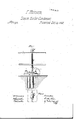
In the accompanying drawings v 'Figure I is a sectional elevation of my improved apparatus.
Figure II is a ground-plan oflsame.
Figure III is a side elevation, taken at right angles to Fig. I.
Figure IV is a plan View of condensing-vessel.
Like letters referto like arts in each of the iigures.
A rpresentslelco Newer, Wliclrmay be' constructed according to the common rules for injectioncondenser-s, as to form, size, and material, although a form which makes a horizontal section of equal or greater length and breadth than a vertical one is preferable.
B represents the main, injection-pipe rising omthe supply-well VC, and entering .the condenser A at one end, near the top, passes horizontally abouttwo-thirds of the distance across the same, the pipe 'within the condenser being perforated with small holes, yto shower the water therein. l
- rl d, d2' represent the waste-pipes connecting 'with the condenser at the bottom, and leading downward to the waste-well E and drain E. The pipe d may be of larger diameter, and project'up a few inches into lthe condenser, to act as an overiiow, to prevent the possiv bility of the condenser being Hooded with injection-4 water.
Presupposing the vacuum obtained in the condenser to be perfect, or nearly so, it must be sufficiently elevated above the level of the waste-well to allowthe Waste-pipes a vertical'length of at least thirty-three feet. v
F represents the exhaust-pipe leading` from the engine G to the condenser, into which it opens on the side opposite the'injection-pipe.
H represents a pump of any approved construction, applied to the vinjection-pipe at any convenient point, in such manner as to raise the injection-water from the supply-well to the condenser.
The operation'of my apparatus, so far as thesame 'is above described, is as follows:
'The .exhaust steam, when the engine is iirstput .in motion, will ilow through the exhaust-pipe F into the condenser, when it will come in contact with the injection-water discharged therein, through the injec-l 'waste-pipes a few feet ion-pipe B, by the action of the pump l-I. This con- ,Y act of the" injection-water; and 4steam will condense he latter, which, together with the injection-water, vill. fall tothe bottom of the condenser, andbe carried if by the wastepipes 'd d* d. The descending columns amns, their 'buoyancy being overcome by the velocityr with which said ,columns move. The expansibility of the assists its escape with the water, since the descending columns remove the pressure upon one side of the body of air` conlined in the condenser, and its expansibility eauses'it to seek egress at such point with the water...`
The pump will, on the start, require to raise the Water the full length ofthe injectie Y-pipe, but in proportion as the'vacuum becomes established in the condenser, atmospheric pressure will assist the pump, and decrease Ithe powerrequired-to operate the same.
The length of the injection-pipe will be governed by, ghe elevation of the watersupply above 'the wasteram.
Assuming the most unfavorable conditions, viz, the
supply and waste being on the same level, the-length .ofthe injection-pipe will be equal to that of the wastepipes plus the height from the bottomrof the condenser 'to the iniectionriflce. -The length of the waste-pipes will in practice be about thirty-four feet, and the additional length om one to three feet, so that under the most unfavorable'circumstances, the length' of the hijection-pipe will'noitexceed thirty-seven feet.
Assuming the most perfect vacuum which may be obtained inthe condenserfro be equal to fourteen pounds, whie'h`s`iii` accordance withpractice," the pump would have to raise the injection-water only nine feet. This might be still xrther reduced by shortening the wastepipes and lowering the condenser, for the reason that the vacuum of fourteen pounds would not sustain a column of over twenty-eight pounds, and the wastepipes will carry oil' the injection-water whenever their length is in excess of the column which the obtained vacuumwill sustain.` l l I But it isjound 'advisable in practice to give the of additional length, as the velocity with which thefwater will discharge is thereby increased, and, in consequence, the percentage of air which it will carry off with it.
It is also` found inI practice that the smaller the bore of the waste-pipes, (the requied capacity being made upfby an increase in their numben) the larger the pecentage of air which the waste-water will carry olf, and
as the successful operation of the apparatus depends upon its capacity to carry off the air which enters with the injection-water, and which may leak in at defective joints, the importancel of this feature is manifest; and,
further, the vacuum is not only maintained butperfected bythisfmeansi-- 3, L It may be here onse "ed, that'the relative position of the parts, except as to verticaldistanees, is of little importance, and may {be made to suit the ever-varying circumstances of loc ion. ,y v 'It is also manifest hatthe pump may be dispensed with when an equivalent natural command. Several inferio mddiiications of the apparatusv he made, as the application of a small air-pumpto exhaust the air from thecondenser in the first instance and carry oil such air' as may enter or leak therein during its operation. Butthis same result is accomplished by the `multiplication ,of waste-pipes, as scribed. A pump might also be applied to the waste pipes, and their length and that of the injectiompipe decreased to such an extent as that the injection-water would dow into the condenser from atmospheric pressure alone.
My apparatus may. further beused for the purpose of producing a vacn without acting as a condenser. I will now descxib .the fourth feature of my invention.
injection-pipe, and, entering the condensing-chamber at oneside, 'presents its end to the month of the exhaustfpipe A portion of the condensing-water entering by this pipe is thrown directly in contact with thc steam as it first enters the condenser, and its volume being comparatively small, it will receive all the heat from the steam it is capable of holding in the form of water, and as it falls upon the bottom of the condenser, it is prevented from mingling with the main portion ofthe injcation-waterV by the partition-.AC the condensing-wafer being raised to the highest possible-temperatuur, 'is is conducted thereto condenser to the feed-pump K.
The higherv the temperature of the feed-water, the less the quantity of the fuel which will be required to convertit into steam, so that a very material saving in fuel will be the result of this arrangement.
The pipe I is provided with avalve or cock, I', by which the quantity of water passing through it may be regulated according to the demands of the boiler.
Having thus described my invention,
What I claim, anddesire to secure by Letters Pat' ent, is-L- 1. The arrangement, with the condenser A, and main induction-pipe B, f the overflow-pipe d, and small pipes d? d2,- as herein set forth.
2. The arrangement of the secondary injectionfpipe I, in relation to the partitioned condenser A, and
Aboiler-feedpipe J,as set forth.
Witnesses: FRANKLIN RANSOM.
W: H. Feesten,
V. H. Bremse.
head of water is at I represents a small pipe, branching from the main f' This portion of i to feedtheboileiand the pipe J, leading from the l i
Publications (1)
| Publication Number | Publication Date |
|---|---|
| US83092A true US83092A (en) | 1868-10-13 |
Family
ID=2152585
Family Applications (1)
| Application Number | Title | Priority Date | Filing Date |
|---|---|---|---|
| US83092D Expired - Lifetime US83092A (en) | Improvement in condensers |
Country Status (1)
| Country | Link |
|---|---|
| US (1) | US83092A (en) |
-
0
- US US83092D patent/US83092A/en not_active Expired - Lifetime
Similar Documents
| Publication | Publication Date | Title |
|---|---|---|
| US83092A (en) | Improvement in condensers | |
| US25360A (en) | William barnes | |
| US214463A (en) | Improvement in safety-regulators for pumps and water-pipes | |
| US791811A (en) | Pressure-valve for steam-heating systems. | |
| US114142A (en) | Improvement in combined heater and condenser | |
| US314559A (en) | Heating and purifying feed-water | |
| US390537A (en) | Feed-water heater | |
| US91770A (en) | Improvement in steam-engine condensers | |
| US493123A (en) | Condenser | |
| US785473A (en) | Exhaust heating or low-pressure system. | |
| US796839A (en) | Evaporator. | |
| US615830A (en) | Charles e | |
| US367851A (en) | John james boyle | |
| US92357A (en) | Self and a | |
| US43976A (en) | Improvement in hydroatmospheric condensers | |
| US462271A (en) | Exhaust steam | |
| US680583A (en) | Combined steam-condenser and oil-separator. | |
| Low | Condensers: A Series of Lectures and Articles Upon the Subject, Reprinted from the Columns of Power | |
| US137796A (en) | Improvement in steam pumps and condensers | |
| US577925A (en) | Feed-water heater for boilers | |
| US683440A (en) | Feed-water heater and purifier. | |
| US196902A (en) | Improvement in compound condensing apparatus for steam-engines | |
| US809022A (en) | Automatic lift-separator. | |
| US39978A (en) | Improved apparatus for condensing oil-vapors | |
| US18861A (en) | Thomas prosser |