US8250446B2 - Decoder device and decoding method - Google Patents
Decoder device and decoding method Download PDFInfo
- Publication number
- US8250446B2 US8250446B2 US12/071,903 US7190308A US8250446B2 US 8250446 B2 US8250446 B2 US 8250446B2 US 7190308 A US7190308 A US 7190308A US 8250446 B2 US8250446 B2 US 8250446B2
- Authority
- US
- United States
- Prior art keywords
- external information
- exponent
- unit
- bit
- information
- Prior art date
- Legal status (The legal status is an assumption and is not a legal conclusion. Google has not performed a legal analysis and makes no representation as to the accuracy of the status listed.)
- Expired - Fee Related, expires
Links
Images


Classifications
-
- H—ELECTRICITY
- H03—ELECTRONIC CIRCUITRY
- H03M—CODING; DECODING; CODE CONVERSION IN GENERAL
- H03M13/00—Coding, decoding or code conversion, for error detection or error correction; Coding theory basic assumptions; Coding bounds; Error probability evaluation methods; Channel models; Simulation or testing of codes
- H03M13/29—Coding, decoding or code conversion, for error detection or error correction; Coding theory basic assumptions; Coding bounds; Error probability evaluation methods; Channel models; Simulation or testing of codes combining two or more codes or code structures, e.g. product codes, generalised product codes, concatenated codes, inner and outer codes
- H03M13/2957—Turbo codes and decoding
-
- H—ELECTRICITY
- H03—ELECTRONIC CIRCUITRY
- H03M—CODING; DECODING; CODE CONVERSION IN GENERAL
- H03M13/00—Coding, decoding or code conversion, for error detection or error correction; Coding theory basic assumptions; Coding bounds; Error probability evaluation methods; Channel models; Simulation or testing of codes
- H03M13/37—Decoding methods or techniques, not specific to the particular type of coding provided for in groups H03M13/03 - H03M13/35
- H03M13/39—Sequence estimation, i.e. using statistical methods for the reconstruction of the original codes
- H03M13/3905—Maximum a posteriori probability [MAP] decoding or approximations thereof based on trellis or lattice decoding, e.g. forward-backward algorithm, log-MAP decoding, max-log-MAP decoding
-
- H—ELECTRICITY
- H03—ELECTRONIC CIRCUITRY
- H03M—CODING; DECODING; CODE CONVERSION IN GENERAL
- H03M13/00—Coding, decoding or code conversion, for error detection or error correction; Coding theory basic assumptions; Coding bounds; Error probability evaluation methods; Channel models; Simulation or testing of codes
- H03M13/65—Purpose and implementation aspects
- H03M13/6577—Representation or format of variables, register sizes or word-lengths and quantization
- H03M13/658—Scaling by multiplication or division
-
- H—ELECTRICITY
- H03—ELECTRONIC CIRCUITRY
- H03M—CODING; DECODING; CODE CONVERSION IN GENERAL
- H03M13/00—Coding, decoding or code conversion, for error detection or error correction; Coding theory basic assumptions; Coding bounds; Error probability evaluation methods; Channel models; Simulation or testing of codes
- H03M13/65—Purpose and implementation aspects
- H03M13/6577—Representation or format of variables, register sizes or word-lengths and quantization
- H03M13/6588—Compression or short representation of variables
Definitions
- the present invention relates to a decoder device performing iteration decoding and a decoding method.
- FIG. 1 is a configuration example of a turbo encoder 200 (e.g., 3GPP Technical Specification TS25.212).
- FIG. 2 is a diagram showing a configuration example of a turbo decoder 400 (e.g., C. Berrou, A. Glambi, and P. Thitimajshima, “Near Shannon limit error-correcting coding and decoding: Turbo-codes (1),” in proc. of the IEEE int. conf. on Communications (ICC'93), Geneva, 1993, pp. 1064-1070).
- a turbo decoder 400 e.g., C. Berrou, A. Glambidar, and P. Thitimajshima, “Near Shannon limit error-correcting coding and decoding: Turbo-codes (1),” in proc. of the IEEE int. conf. on Communications (ICC'93), Geneva, 1993, pp. 1064-1070.
- the turbo encoder 200 includes, as shown in FIG. 1 , a first element encoder 210 , a second element encoder 230 and an interleaver 220 .
- Information bits are input to the turbo encoder 200 and are encoded by the first element encoder 210 to generate first parity bits. Also, the input information bits are input to the interleaver 220 and are interleaved by the interleaver 220 .
- the interleaved bits are input to the second element encoder 230 and are encoded to generate second parity bits. Further, the information bits themselves are output as systematic bits. Then, for example, these three kinds of bits are combined to form serial bits which are modulated for transmission.
- the turbo decoder 400 includes, as shown in FIG. 2 , a first element decoder 410 , a second element decoder 420 , an interleaver 411 and a deinterleaver 421 .
- a demodulated receiving likelihood data is input to the turbo decoder 400 (ys corresponding to the systematic bits, yp 1 and yp 2 respectively corresponding to the two parity bits).
- the likelihood ys corresponding to the systematic bits, the likelihood yp 1 corresponding to the first parity bits and an external information L′e ( 2 ) are input to the first element decoder 410 , and an external information Le ( 1 ) is output.
- the output Le ( 1 ) and the likelihood ys corresponding to the systematic bits are input to the interleaver 411 , and then output respectively after the bits are interleaved.
- the reason why there is the interleaver 411 is that the second parity bit is interleaved by the interleaver 220 at the time of decoding, which has to correspond to the processing at the time of encoding.
- the likelihood ys corresponding to the systematic bits whose bits are interleaved, the external information L′e ( 1 ) and the likelihood ys 2 corresponding to the second parity bits are input to the second element decoder 420 , and an external information Le ( 2 ) is output.
- the external information Le ( 2 ) is interleaved to the likelihood of an original string by the deinterleaver 421 , and is output as the external information L′e ( 2 ).
- a decoding bit uj is output from the deinterleaver 421 .
- An error rate characteristic of the decoding bit uj is improved because of this iterative process.
- FIG. 3 is a diagram showing a configuration example of the first element decoder 410 , the second element decoder 420 of the turbo decoder 400 and the surrounding part (e.g., J. Vogt and A. Finger, “Improving the max-log-MAP turbo decoder,” Electronics Letters 9 Nov. 2000, Vol. 36, No. 23, pp. 1937-1939).
- Each of the element decoders 410 and 420 includes a MAP computing unit 415 and adding units 416 and 417 .
- a posteriori probability is generated by a MAP (Maximum a Posteriori) calculation.
- the likelihood obtained by taking a log of the value of the probability is input to the MAP computing unit 415 as shown for a log-MAP calculation.
- a prior (probability) likelihood is reduced from the generated posteriori likelihood (ys+L′e) and the external information (return posteriori) is output.
- Max-log-MAP calculation is a method approximating a “sum of exponent functions of likelihood”, the most major calculation element, by the maximum value of each section of the sum.
- a coefficient scaling unit 430 has a method for multiplying a number which is smaller than “1” (e.g., J. Vogt and A. Finger, “Improving the max-log-MAP, turbo decoder,” Electronics Letters 9 Nov. 2000, Vol. 36, No. 23, pp. 1937-1939.
- this method is referred to as “coefficient scaling”.
- coefficient scaling It is known that the error rate characteristic is improved by this method.
- a scaling value “0.75” is used in view of a circuit implementation.
- FIG. 4 is a diagram showing a configuration example of the method.
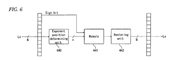
- An output side of the element decoders 410 and 420 (the return likelihood (external information) after the log-MAP calculation) is provided with an indexing unit 440 , a memory storage unit 441 and a restoring unit 442 .
- FIG. 5 is a diagram showing an example of the processing performed from the exponent position determining unit 440 to the restoring unit 442 .
- FIG. 6 is a diagram showing a detailed configuration example of processing performed from the exponent position determining unit 440 to the restoring unit 442 .
- indexation there may be a waste of memory when information is not assigned to the exponent.
- the value of the external information can be reduced and the error rate characteristic can be improved.
- the value is different from the actual value because the value is an approximate value. Degradation of the characteristic occurs due to the approximation such as in case a level of the average numeric value is kept unchanged.
- described examples of a decoder device and a decoding method reduce degradation of an error rate characteristic, reduce a waste in the memory, or reduce degradation of the error rate characteristic caused by approximation.
- a decoder including an element decoding unit generating external information for input data, including an exponent position determining unit, when the external information output from the element decoding unit is input, of information excluding a sign bit from the external information, specifying an exponent that is a bit position where a value different from a sign bit first appears, a mantissa obtaining unit obtaining information of 1-bit or a plurality of bits in a position next to the exponent as a mantissa out of the external information, a storage unit storing the exponent and the mantissa and a restoring unit restoring the external information by reading the exponent and the mantissa stored in the storage unit, wherein the element decoding unit performs iteration decoding based on the restored external information is utilized.
- FIG. 1 is a diagram showing a configuration example of a turbo encoder.
- FIG. 2 is a diagram showing a configuration example of a turbo decoder.
- FIG. 3 is a diagram showing a configuration example of an element decoder and a surrounding part.
- FIG. 4 is a diagram showing a configuration example of an element decoder and a surrounding part.
- FIG. 5 is a diagram illustrating an example of processing according to the conventional technology.
- FIG. 6 is a diagram showing a surrounding part of an element decoder.
- FIG. 7 is a diagram showing a configuration example of an element decoder and a surrounding part.
- FIG. 8 is a diagram illustrating an example of processing.
- FIG. 9 is a diagram showing a configuration example of an external information processing unit.
- FIG. 10A is a flow chart of memory storing processing and FIG. 10B is a flow chart of memory reading processing.
- FIG. 11 is a diagram showing another configuration example of an element decoder and a surrounding part.
- FIG. 12 is a diagram showing another configuration example of an external information processing unit.
- FIG. 13 is a diagram showing another configuration example of an external information processing unit.
- FIG. 14 is a diagram showing a configuration example of a receiver.
- FIG. 15 is a diagram illustrating an example of processing.
- FIG. 16 is a diagram showing another configuration example of an external information processing unit.
- FIG. 17A is a flow chart of memory storing processing
- FIG. 17B is a flow chart of memory reading processing.
- FIG. 18 is a diagram illustrating an example of processing.
- FIG. 19 is a diagram showing another configuration example of an external information processing unit.
- FIG. 20 is a diagram showing an example of a table.
- FIG. 21 is a diagram showing an example of a table.
- FIG. 22A is a flow chart of memory storing processing
- FIG. 22B is a flow chart of memory reading processing.
- FIG. 23A is a flow chart of memory storing processing
- FIG. 23B is a flow chart of memory reading processing.
- FIG. 24 is a diagram showing a configuration example of a surrounding part of a turbo decoder.
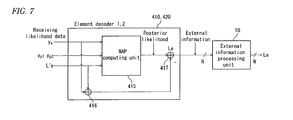
- FIG. 7 is a diagram showing a example of element decoders 410 and 420 of a turbo decoder and the surrounding part to be used in the turbo decoder shown in FIG. 2 .
- the turbo decoder 400 includes an external information processing unit 10 in an output stage of the element decoders 410 and 420 .
- the external information processing unit 10 performs various calculating processing for external information (return likelihood) and outputs the external information after the calculation to the element decoders 420 or 410 .
- FIG. 9 shows a configuration example of the external information processing unit 10 according to example 1.
- FIG. 8 is a diagram illustrating an example of the processing.
- FIG. 8 An example of the processing according to example 1 is explained by using FIG. 8 .
- “209” in a decimal number
- the sign bit “ 0 ” of the input external information is stored in the memory as it is.
- a bit position hereinafter referred to as “exponent”
- the exponent is “8”.
- the value “1000” expressing the exponent “8” in a binary number is stored in the memory.
- information of 2-bits in a position next to the bit position of the exponent is stored in the memory as a mantissa.
- “10” binary number
- the value of the mantissa field is added to the exponent to restore the value.
- “1” is set in the “8”th bit for the exponent field “1000”, and also the mantissa field “10” is added to the 7th bit and the 6th bit.
- the restored value is expressed “192” in a decimal number, and the ratio of the output to the input is “0.919”. Although the ratio varies according to the value of the input external information, the average ratio is slightly larger than “0.7”.
- FIG. 9 is a diagram showing a configuration example of the external information processing unit 10 according to example 1.
- the external information processing unit 10 includes an exponent position determining unit 11 , a mantissa field obtaining unit 12 , a memory 13 and a restoring unit 14 .
- the exponent position determining unit 11 determines the position (exponent) where the bit different from the sign bit first appears for the external information excluding the sign bit.
- the determined exponent is output to the memory 13 to be stored.
- the mantissa field obtaining unit 12 obtains 2-(or 1 or multiple bits) bits of information (mantissa) in the position next to the exponent position for the external information excluding the sign bit.
- the obtained information is output to the memory 13 as the mantissa to be stored in the memory.
- the memory 13 stores the information of the exponent field, the mantissa field and the sign bit in the memory.
- the restoring unit 14 reads the sign bit, the values of the exponent and the mantissa from the memory storage unit 13 , respectively, in order to restore the external information.
- the restored external information is input as prior likelihood to the element decoders 420 and 410 as follows.
- FIG. 10A is an example of a flow chart showing the processing according to example 1.
- the sign bit of the input external information is stored in the memory 13 (Step 11 ).
- the sign bit can be obtained in, for example, the exponent position determining unit 11 .
- Step 14 the values of the exponent field and the mantissa field are stored in the memory storage unit 13 (Step 14 ), and the processing for memory storing is finished (Step 15 ).
- Step 20 If the memory reading processing shown in FIG. 10B is started (Step 20 ), the restoring unit 14 reads the sign bit from the memory 13 (Step 21 ), and also reads the values of the exponent and the mantissa (Step 22 ).
- the restoring unit 14 first restores the exponent (Step 23 ) then adds the mantissa to the exponent for restoring (Step 24 ), and finishes the processing (Step 25 ).
- bit number obtained as the exponent field is “2”. However, bit number “ 1 ”, “ 3 ” or the like is applicable.
- FIG. 11 is a diagram showing a configuration example of the surrounding part of the element decoders 410 and 420 according to the present example 2.
- the other configuration is the similar to that of example 1.
- a coefficient scaling unit 15 As shown in FIG. 11 , a coefficient scaling unit 15 , an indexing unit 16 , memory 17 and a restoring unit 18 are provided for the output (external information) output from the element decoders 410 and 420 .
- the external information processing unit 10 of FIG. 7 corresponds to the coefficient scaling unit 15 through the restoring unit 18 .
- the coefficient scaling unit 15 multiplies the external information by a certain coefficient (a value which is smaller than “1”), and outputs the multiplied external information.
- the indexing unit 16 specifies the exponent position in accordance with the multiplied external information, and outputs the exponent to the memory 17 .
- the memory 17 stores the value of the exponent and the sign bit in the memory.
- the sign bit is obtained in the indexing unit 16 .
- the restoring unit 18 reads the sign bit and the exponent from the memory storage unit 17 to restore the external information.
- the restored external information is input as a prior likelihood to the element decoders 420 or 410 for the further decoding process.
- the indexation is performed by the indexing unit 16 for the output that is output from the coefficient scaling unit 15 . It is possible to improve the problem that the memory size has to be increased by the “coefficient scaling” because the memory size can be reduced by the “indexation”. It is also possible to improve the problem that degradation of the error rate characteristic is caused by the “indexation” because the degradation can be improved by the “coefficient scaling”.
- the indexation method for adding the “mantissa field” according to example 1 can be performed in the same way.
- FIG. 12 and FIG. 13 are diagrams showing a configuration example of the external information processing unit 10 according to the present example 3.
- the other configuration is the same as that of example 1.
- the external information processing unit 10 includes a right-shift unit 20 , a memory 21 and a coefficient scaling unit 22 .
- the right-shift unit 20 performs a shift calculation of m-bits towards the right side for external information Le of N-bits, and the memory storage unit 21 stores (N ⁇ m) bits in the memory.
- the coefficient scaling unit 22 multiplies the external information of (N ⁇ m) bits which is read by the memory storage unit 21 by the coefficient value and outputs the external information of a prescribed scaling value.
- FIG. 13 is a diagram showing a configuration example of the external information processing unit 10 in case an overall scaling value is “0.75”.
- the external information processing unit 10 includes a 2-bit right-shift unit 25 , a memory 26 , a 1-bit left-shift unit 27 and an adding unit 28 .
- the 2-bit right-shift unit 25 reduces the number of bits to the number of (N ⁇ 2) bits by shifting 2 bits to the right.
- a buffer size can be reduced by storing the obtained information in the memory of the memory storage unit 26 .
- the stored external information is read by the 1-bit left-shift unit 27 to be shifted to the left side (twofold).
- the adding unit 28 adds this output value to the external information output from the memory 26 .
- the external information stored in the memory is multiplied by the three times coefficient value by the 1-bit left-shift unit 27 (twofold) and the adding unit 28 . Therefore, for the input external information Le of N-bits, this achieves (1 ⁇ 4) ⁇ Le ⁇ 3 ⁇ (3 ⁇ 4) ⁇ Le, and “0.75” times which is the predetermined scaling value,
- the memory size can be reduced by combining a shift circuit and an adder for input external information of N-bits as well as avoiding degradation of the error rate characteristic by the “coefficient scaling”. Also, an actual implement is easy because the circuit can be implemented by using the shift circuit and the adder.
- the present example 4 is an example for determining the appropriate indexation method based on the encoding rate and the modulation method.
- FIG. 14 is a diagram showing a configuration example of a receiver 100 according to the present example 4.
- the receiver 100 is, for example, a receiver in a 3GPP mobile communication system.
- the receiver 100 includes a first demodulation unit 101 and a second demodulation unit 104 , a format obtaining unit 102 , an indexation method determining unit 103 , a data processing unit 105 and an error correction decoder 106 .
- a control channel and a data channel are input to the receiver 100 .
- the first demodulation unit 101 demodulates the control channel, and the format obtaining unit 102 obtains an encoding format from the control channel. For example, the information of the encoding rate and the modulation method is obtained.
- the indexation method determining unit 103 determines the indexation method based on the obtained encoding format.
- the second demodulation unit 104 demodulates the data channel by a predetermined modulation method (16QAM, QPSK or the like).
- the data processing unit 105 processes the demodulated data to obtain data to be decoded and outputs the data to the error correction decoder 106 .
- the process can include descrambling or the like when the transmitter applies scrambling of data to transmit the data through the radio path.
- the error correcting decoder 106 includes the turbo decoder 400 , shown in FIG. 24 , having the element decoders 410 and 420 shown in FIG. 1 and FIG. 2 , and the turbo decoder 400 having the element decoders 410 and 420 shown in FIG. 7 and the like. In the error correcting decoder 106 , any of the turbo decoders 400 is performed and decoded based on the selected information.
- FIG. 15 is a diagram illustrating an example of the processing according to the present example 5.
- FIG. 16 is a diagram showing a configuration example of the external information processing unit 10 ( FIG. 1 ).
- FIG. 17 (A) and FIG. 17 (B) are diagrams showing an example of the flow charts, respectively.
- the indexation method of the present example is referred to as a “minimum error indexation method”.
- the external information “209” (decimal number) is input to the external information processing unit 10 .
- the position of the exponent is first obtained.
- the exponent is “8”.
- “rounding off” is performed in order to obtain a higher-accuracy exponent.
- the bit is stored in the memory as the mantissa to be restored. However, the bit is “rounded off” in the present example 5.
- the restoring value is “256” (decimal number), and the rate of the input to the output is “1.225” times. As well as in example 1, there storing value is particularly effective for decoding data with a high encoding rate.
- FIG. 16 is a diagram showing a configuration example of the external information processing unit 10 .
- the external information processing unit 10 includes an exponent position determining unit 30 , a lower digit bit obtaining unit 31 , an adding unit 32 , a memory 33 and a restoring unit 34 .
- the exponent position determining unit 30 determines the exponent position of the input external information, and outputs the value to the adding unit 32 .
- the lower digit bit obtaining unit 31 obtains the digit which is one digit lower than the exponent position, and outputs the value of the digit (001000000) to the adding unit 32 .
- the adding unit 32 adds the exponent to the digit which is one digit lower than the exponent, and outputs the added exponent (0100010001) to the memory storage unit 33 .
- the memory storage unit 33 stores the exponent after adding and the sign bit of the input external information in the memory.
- the sign bit can be obtained by the exponent position determining unit 30 .
- the restoring unit 34 restores the external information by reading the sign bit and the exponent position.
- the restored external information is output to the element encoders 420 and 410 for the further decoding process.
- FIG. 17 (A) and FIG. 17 (B) are examples of flow charts showing the operation of the processing. Briefly explaining, when the present processing is started (Step 30 ), the sign bit is obtained for the external information and is stored in the memory 33 (Step 31 ).
- the exponent position m is specified in the exponent position determining unit 30 (Step 32 ), and “2 ⁇ (m ⁇ 2)” is added in the adding unit 32 (Step 33 ).
- the adding unit 32 stores the exponent position in the memory 33 (Step 37 ), and the storing process in the memory is finished (Step 38 ).
- Step 40 If the memory reading processing is started (Step 40 ), in the restoring unit 34 , the sign bit and the value of the exponent field (the mantissa field, if it exists) are read from the memory storage unit 33 (Step 41 , Step 42 ), and the external information is restored (Step 43 ). Then, the processing is finished (Step 44 ).
- FIG. 18 is a diagram illustrating the processing according to the present example 6.
- FIG. 19 is a configuration example of the external information processing unit 10 according to the present example 6.
- FIG. 20 and FIG. 21 are examples of tables, and FIG. 22 (A), FIG. 22 (B), FIG. 23 (A) and FIG. 23 (B) are diagrams showing examples of the flow charts, respectively.
- the value of the bit in the position on the right side of the exponent position (the position of the 7th bit) is obtained.
- the exponent is “1”.
- the table is referred to for this exponent position and the value of the bit next to the exponent position, “0011000000”.
- the exponent “14” is obtained by referring the table shown in FIG. 20 .
- the value expressing the exponent value as a binary number (“1110”) is stored in the memory together with the sign bit.
- the group obtaining the exponent “14” is again read from the table reference unit 43 , and is obtained as the restoring value (“0011000000”).
- the memory storage unit 33 can store sixteen kinds of values because the amount of the memory 33 is 4-bit. However, there are ten kinds of exponents from “0” to “9” which are actually used, and the exponents from “10” to “15” are not stored.
- the number of bit of original data is “N”
- the value “1” in the mantissa filed which is the bit next to the exponent field is added in order to assign some numeric values which can not be expressed by indexation.
- numeric values are newly assigned for the exponents from “10” to “15”.
- the exponent is the bit position where the bit different from the sign bit first appears in searching it from the left side digit to right side digit.
- the exponent “4” is expressed as “0000001000”, a bit string in which “1” first appears in the position of the 4th bit.
- the mantissa field of 1-bit is the value of the bit in the digit which is one digit lower than the exponent position.
- the exponent “4” is stored in the memory as it is with reference to the table 431 . If the bit which is one digit lower than the exponent “4” is “1”, that is, if the mantissa field is “1” (the value is “0000001100”), the exponent “10” is stored in the memory with reference to the table 431 .
- a binary value corresponding to the exponent “14” is stored in the memory.
- a numeric value corresponding to the exponent “14” is again read from the table 431 by the table reference unit 43 in order to obtain the restoring value “192” (decimal number),
- the rate of the output “192” to the input “209” is “0.919” times, and the storing value which becomes effective by the high encoding rate which is the same as that of example 1 is obtained.
- What is actually stored in a ROM or the like as the table 431 may be the exponent only from “10” to “15” of the table 431 . This is because, as for the other value, the external information can be restored by storing the value itself of the exponent in the memory and reading the value.
- the external information processing unit 10 includes an exponent position determining unit 40 , a switch 41 , a mantissa field obtaining unit 42 , a table reference unit 43 , a memory 44 and a restoring unit 45 .
- the exponent position determining unit 40 determines an exponent position of the external information.
- the switch 41 switches whether the exponent position is stored in the memory 44 (if the value of the mantissa field is “0”) or the exponent position is output to the mantissa field obtaining unit 42 (if the mantissa field is “1”), depending on whether the value of the 1-bit mantissa field is “0” or “1”.
- the mantissa field obtaining unit 42 obtains only 1-bit of the value of the mantissa field for the input external information.
- the table 431 stores the exponents from “10” to “15” and corresponding numeric values of the table 431 shown in FIG. 20 .
- the mantissa field obtaining unit 42 obtains the exponent by the obtained exponent and the value of the mantissa with reference to the table 431 .
- the obtained exponent is stored in the memory 44 .
- the restoring unit 45 restores the external information by reading the sign bit and the exponent from the memory 44 .
- the restored external information is output to the element decoders 420 or 410 for further decoding process.
- FIG. 21 is an example of a table 432 to which the other value is assigned.
- the exponent is assigned to the table 432 in order of greater numeric value. This is because that it is possible to reduce the error of the external information to be restored if the exponent is assigned in order of numeric value of greater digit instead of smaller digit.
- the configuration of the external information processing unit 10 can be same as that of the example of FIG. 20 .
- FIG. 22 (A) and FIG. 22 (B) are an example of the flowcharts according to the present example 6.
- the example uses the table 431 ( FIG. 20 ).
- Step 50 If the memory storing processing is started (Step 50 ), the sign bit is obtained in the exponent position determining unit 40 and is stored in the memory 44 (Step 51 ).
- the exponent position m is specified in the exponent position determining unit 40 (Step 52 ). Then, it is determined whether or not the exponent position m is greater than (N ⁇ 1 ⁇ k) (N is the bit number of the external information to be input, and k is the number of numeric value (“6” in the example of FIG. 20 ) assigned to the table 432 ) (Step 53 ).
- the obtained exponent m is stored as the index in the memory 44 as it is (Step 59 , Step 57 ).
- Step 58 the sequence of the memory storing processing is finished.
- Step 60 if the present processing is started (Step 60 ), the sign bit is read from the memory 44 in the restoring unit 45 (Step 61 ). Then, an index i is read from the memory 44 .
- the restoring unit 45 determines whether or not the index i is greater than (N ⁇ 1) (Step 63 ). That is, in the example of FIG. 20 , since the value having the exponent which is greater than “9” is stored in the table 432 , it is determined whether or not there is a need to refer to the table 432 .
- Step 64 restores the numeric value (Step 65 ), and finishes the processing (Step 66 ).
- the restoring unit 45 does not have to refer to the table 431 .
- the index i is regarded as the exponent as it is (Step 67 ), and the numeric value is restored (Step 65 ).
- FIG. 23 (A) and FIG. 23 (B) are an example of the flow charts when the table 432 shown in FIG. 21 is used. The explanation of the processing which is the same as that of FIG. 22 (A) is omitted.
- the exponent position determining unit 40 determines whether or not the exponent m is greater than the value (min ⁇ m) (Step 73 ).
- the value (min ⁇ m) shows the minimum value of the exponents included in ( ⁇ N ⁇ 1 ⁇ ) of the table 432 .
- the exponent position “7” of the numeric value “0001100000” which is assigned as the exponent “13” becomes the minimum value (min ⁇ m) of the exponent. It is determined whether or not to refer to the table 432 shown in FIG. 21 by comparing the minimum value and the obtained exponent.
- the exponents from “10” to “15” are stored in the table 432 as well as in the example of FIG. 22 (A).
- the table reference unit 43 assigns “0” to a value s and obtains the mantissa bit bin the position (m ⁇ 1 ⁇ s). Since the value s is “0”, the position (m ⁇ 1), that is, the value of bit on the right side of the exponent m, is obtained as the mantissa.
- the table reference unit 43 determines whether or not the value s is “0”. If the value s is not “0” (No in Step 78 ), the index (the value of the exponent) is specified with reference to the table 432 (Step 79 ). Then, the table reference unit 43 stores the index in the memory 44 (Step 80 ), and the sequence of the memory storing processing is finished (Step 81 ).
- Step 78 if the value s is “0” (Yes in Step 78 ), there is no need to refer to the table 432 and the obtained exponent can be stored as it is to be restored.
- the obtained exponent is regarded as the index (Step 82 ) and is stored in the memory 44 (Step 80 ).
- Step 73 If the exponent m is smaller than the value (min ⁇ m) (No in Step 73 ), no value which is to be referred in the table 432 is stored, so that the obtained exponent is stored in the memory 44 as the index (Step 82 , Step 80 ).
- Step 93 it is determined whether or not there is a need to refer to the table 432 by the index i which is read from the memory 44 (Step 93 ). If there is a need (Yes in Step 93 ), the table 432 is referred to restore the numeric value (Step 94 , Step 95 ). If there is no need, the index i is regarded as the exponent m as it is and the numeric value is restored (Step 97 , Step 95 ).
- the example of the flow chart is the same as that of FIG. 22 (B).
- mantissa field can be “3” bit, “4” bit or the like.
- FIG. 24 is a diagram showing a configuration example of the surrounding part of the turbo decoder 400 according to the present example 8.
- the configuration of the turbo decoder 400 is the same as that of example 1.
- a previous stage of the turbo decoder 400 includes indexing units 451 , 453 , 455 and memories 452 , 454 , 456 .
- indexing units 451 , 453 , 455 By providing the indexing units 451 , 453 , 455 in the previous stage of the turbo decoder 400 , amounts of the memories 452 , 454 , 456 can be reduced.
- indexing method of the indexing units 451 , 453 , 455 method for adding the mantissa field shown in example 1 and the “minimum error indexing method” shown in example 5 are applicable. Further, the indexing method of example 6 is also applicable. In either case, the accuracy of approximation can be improved. Also, it is possible to allow for reducing the amount of the memory by using the simple indexing method such as conventional technique.
- the encoder includes a encoder combined with the element decoders 210 , 220 and the interleaver 220 (see FIG. 25 ).
- the decoder includes a MAP decoder (Sum-Product computing unit). The output from the MAP decoder is returned as external likelihood to the MAP decoder for next decoding process.
- the decoding processing is also performed by iteration base decoding.
- a systematic bit string is encoded and 2 parity bit strings are obtained.
- encoding to obtain one or 3 parity bit strings also can be applied.
- the encoding can be performed in a way that three or four of the element decoders 410 , 420 are added to decode such encoding data. Further, the encoding also can be performed for all data of the parity bit strings without the systematic bit string in the same way.
- the turbo decoder 400 is preferred to be applied to, for example, a mobile phone in a mobile communication systematic, an information mobile terminal such as a PDA and the like, or a wireless base station.
- the decoder and the decoding method preventing degradation of the error rate characteristic. Also, the memory size can be prevented from becoming larger. It is also possible to provide the decoder or the like avoiding a waste in the memory. And, it is possible to provide the decoder or the like preventing degradation of the error rate characteristic caused by approximation.
Landscapes
- Physics & Mathematics (AREA)
- Probability & Statistics with Applications (AREA)
- Engineering & Computer Science (AREA)
- Theoretical Computer Science (AREA)
- Error Detection And Correction (AREA)
Abstract
Description
Claims (19)
Applications Claiming Priority (3)
| Application Number | Priority Date | Filing Date | Title |
|---|---|---|---|
| JP2007049376A JP4282725B2 (en) | 2007-02-28 | 2007-02-28 | Decoding device and decoding method |
| JPJP2007-49376 | 2007-02-28 | ||
| JP2007-49376 | 2007-02-28 |
Publications (2)
| Publication Number | Publication Date |
|---|---|
| US20080208939A1 US20080208939A1 (en) | 2008-08-28 |
| US8250446B2 true US8250446B2 (en) | 2012-08-21 |
Family
ID=39492979
Family Applications (1)
| Application Number | Title | Priority Date | Filing Date |
|---|---|---|---|
| US12/071,903 Expired - Fee Related US8250446B2 (en) | 2007-02-28 | 2008-02-27 | Decoder device and decoding method |
Country Status (3)
| Country | Link |
|---|---|
| US (1) | US8250446B2 (en) |
| EP (1) | EP1968200A1 (en) |
| JP (1) | JP4282725B2 (en) |
Families Citing this family (5)
| Publication number | Priority date | Publication date | Assignee | Title |
|---|---|---|---|---|
| US8239745B2 (en) * | 2009-06-02 | 2012-08-07 | Freescale Semiconductor, Inc. | Parity data encoder for serial communication |
| CN101777926B (en) * | 2010-01-12 | 2014-04-16 | 浙江大学 | General decoder of Turbo product code and method thereof |
| JP5696604B2 (en) * | 2011-06-30 | 2015-04-08 | 富士通株式会社 | Error correction code decoding apparatus, error correction code decoding method, base station apparatus, and mobile station apparatus |
| JP5991580B2 (en) * | 2012-08-01 | 2016-09-14 | Necエンジニアリング株式会社 | Turbo decoder, log likelihood ratio calculation apparatus, turbo decoding method, log likelihood ratio calculation method, turbo decoding program, and log likelihood ratio calculation program used therefor |
| WO2019182102A1 (en) * | 2018-03-23 | 2019-09-26 | パナソニック インテレクチュアル プロパティ コーポレーション オブ アメリカ | Three-dimensional data coding method, three-dimensional data decoding method, three-dimensional data coding device, and three-dimensional data decoding device |
Citations (13)
| Publication number | Priority date | Publication date | Assignee | Title |
|---|---|---|---|---|
| US4617641A (en) * | 1983-10-19 | 1986-10-14 | Hitachi, Ltd. | Operation unit for floating point data having a variable length exponent part |
| US5222189A (en) * | 1989-01-27 | 1993-06-22 | Dolby Laboratories Licensing Corporation | Low time-delay transform coder, decoder, and encoder/decoder for high-quality audio |
| US5321725A (en) * | 1991-07-26 | 1994-06-14 | General Instrument Corporation | Method and apparatus for communicating digital information such as compressed video using treillis coded QAM |
| US5781586A (en) * | 1994-07-28 | 1998-07-14 | Sony Corporation | Method and apparatus for encoding the information, method and apparatus for decoding the information and information recording medium |
| US6098192A (en) * | 1997-09-17 | 2000-08-01 | Cirrus Logic, Inc. | Cost reduced finite field processor for error correction in computer storage devices |
| US6754810B2 (en) * | 1997-11-29 | 2004-06-22 | I.P.-First, L.L.C. | Instruction set for bi-directional conversion and transfer of integer and floating point data |
| US6766489B1 (en) * | 1998-11-09 | 2004-07-20 | Canon Kabushiki Kaisha | Device and method of adapting turbocoders and the associated decoders to sequences of variable length |
| US6940428B2 (en) * | 2001-01-31 | 2005-09-06 | Matsushita Electric Industrial Co., Ltd. | Apparatus and method for decoding |
| US7065695B2 (en) * | 2002-05-31 | 2006-06-20 | Broadcom Corporation | Metric calculation design for variable code rate decoding of broadband trellis, TCM, or TTCM |
| US20080059862A1 (en) * | 2006-09-04 | 2008-03-06 | Samsung Electronics Co., Ltd. | Apparatus and method to transmit/receive signal in a communication system |
| US7882414B2 (en) * | 2005-12-07 | 2011-02-01 | Samsung Electronics Co., Ltd | Apparatus and method for transmitting/receiving signal supporting variable coding rate in a communication system |
| US7941736B2 (en) * | 2006-02-22 | 2011-05-10 | Samsung Electronics Co., Ltd | Apparatus and method for receiving signal in communication system |
| US7954033B2 (en) * | 2005-10-31 | 2011-05-31 | Samsung Electronics Co., Ltd | Decoding apparatus and method in a communication system using low density parity check codes |
Family Cites Families (1)
| Publication number | Priority date | Publication date | Assignee | Title |
|---|---|---|---|---|
| JP4690141B2 (en) | 2005-08-09 | 2011-06-01 | 住友電気工業株式会社 | Optical subscriber line terminal equipment and downlink bandwidth control method |
-
2007
- 2007-02-28 JP JP2007049376A patent/JP4282725B2/en not_active Expired - Fee Related
-
2008
- 2008-02-25 EP EP08101922A patent/EP1968200A1/en not_active Withdrawn
- 2008-02-27 US US12/071,903 patent/US8250446B2/en not_active Expired - Fee Related
Patent Citations (13)
| Publication number | Priority date | Publication date | Assignee | Title |
|---|---|---|---|---|
| US4617641A (en) * | 1983-10-19 | 1986-10-14 | Hitachi, Ltd. | Operation unit for floating point data having a variable length exponent part |
| US5222189A (en) * | 1989-01-27 | 1993-06-22 | Dolby Laboratories Licensing Corporation | Low time-delay transform coder, decoder, and encoder/decoder for high-quality audio |
| US5321725A (en) * | 1991-07-26 | 1994-06-14 | General Instrument Corporation | Method and apparatus for communicating digital information such as compressed video using treillis coded QAM |
| US5781586A (en) * | 1994-07-28 | 1998-07-14 | Sony Corporation | Method and apparatus for encoding the information, method and apparatus for decoding the information and information recording medium |
| US6098192A (en) * | 1997-09-17 | 2000-08-01 | Cirrus Logic, Inc. | Cost reduced finite field processor for error correction in computer storage devices |
| US6754810B2 (en) * | 1997-11-29 | 2004-06-22 | I.P.-First, L.L.C. | Instruction set for bi-directional conversion and transfer of integer and floating point data |
| US6766489B1 (en) * | 1998-11-09 | 2004-07-20 | Canon Kabushiki Kaisha | Device and method of adapting turbocoders and the associated decoders to sequences of variable length |
| US6940428B2 (en) * | 2001-01-31 | 2005-09-06 | Matsushita Electric Industrial Co., Ltd. | Apparatus and method for decoding |
| US7065695B2 (en) * | 2002-05-31 | 2006-06-20 | Broadcom Corporation | Metric calculation design for variable code rate decoding of broadband trellis, TCM, or TTCM |
| US7954033B2 (en) * | 2005-10-31 | 2011-05-31 | Samsung Electronics Co., Ltd | Decoding apparatus and method in a communication system using low density parity check codes |
| US7882414B2 (en) * | 2005-12-07 | 2011-02-01 | Samsung Electronics Co., Ltd | Apparatus and method for transmitting/receiving signal supporting variable coding rate in a communication system |
| US7941736B2 (en) * | 2006-02-22 | 2011-05-10 | Samsung Electronics Co., Ltd | Apparatus and method for receiving signal in communication system |
| US20080059862A1 (en) * | 2006-09-04 | 2008-03-06 | Samsung Electronics Co., Ltd. | Apparatus and method to transmit/receive signal in a communication system |
Non-Patent Citations (6)
| Title |
|---|
| 3GPP TS 25.212 V7.3.0; 3rd Generation Partnership Project; Technical Specification Group Radio Access Network; Multiplexing and channel coding (FDD)(Release 7); (Dec. 2006). |
| C. Berrou, A. Glavieux and Punya Thitimajshima, "Near Shannon limit error-correcting coding and decoding: Turbo-codes (1)," in proc. of the IEEE int.conf. on Communications (ICC'93), Geneva, 1993, pp. 1064-1070. |
| Communication from European Patent Office dated Jul. 4, 2008, including Extended European Search Report with written Abstract to the European Search Report for corresponding European Patent Application No. 08101922.6, dated Jun. 26, 2008. |
| D.Garrett, B. Xu, and C. Nicol, "Energy Efficient Turbo Decoding for 3G Mobile," in Int. Symp. on Low Power Electronics and Design, 2001; pp. 328-333. |
| J. Vogt and A. Finger, "Improving the max-log-MAP turbo decoder," Electronics Letters Nov. 9, 2000, vol. 36, No. 23, pp. 1937-1939. |
| J. Vogt, J.Ertel and A. Finger, "Reducing bit width of ext rinsic memory in turbo decoder realizations," Electronics Letters Nov. 28, 2000, vol. 36, No. 20, pp. 1937-1939. |
Also Published As
| Publication number | Publication date |
|---|---|
| JP4282725B2 (en) | 2009-06-24 |
| US20080208939A1 (en) | 2008-08-28 |
| EP1968200A1 (en) | 2008-09-10 |
| JP2008219082A (en) | 2008-09-18 |
Similar Documents
| Publication | Publication Date | Title |
|---|---|---|
| US7814393B2 (en) | Apparatus and method for coding/decoding block low density parity check code with variable block length | |
| RU2595542C2 (en) | Device and method for transmitting and receiving data in communication/broadcasting system | |
| US9319068B2 (en) | Apparatus and method for coding/decoding block low density parity check code in a mobile communication system | |
| US7600174B2 (en) | Apparatus and method for encoding and decoding a block low density parity check code | |
| US11265020B2 (en) | Electronic device with bit pattern generation, integrated circuit and method for polar coding | |
| EP0973268B1 (en) | Method and device for coding and transmission using a sub-code of a product code | |
| US20080028281A1 (en) | Encoding method, decoding method, and devices for same | |
| WO2003103152A2 (en) | Soft decoding of linear block codes | |
| US8250446B2 (en) | Decoder device and decoding method | |
| US6868518B2 (en) | Look-up table addressing scheme | |
| KR102277758B1 (en) | Method and apparatus for decoding in a system using binary serial concatenated code | |
| US20030091129A1 (en) | Look-up table index value generation in a turbo decoder | |
| US20030023919A1 (en) | Stop iteration criterion for turbo decoding | |
| US6886127B2 (en) | Implementation of a turbo decoder | |
| US20070168820A1 (en) | Linear approximation of the max* operation for log-map decoding | |
| US7913153B2 (en) | Arithmetic circuit | |
| KR101562220B1 (en) | Decoding method and apparatus for non-binary low density parity check code | |
| KR100895670B1 (en) | Turbo decoding method using sliding window method, turbo decoder and wireless receiving apparatus performing the same | |
| EP1098447B1 (en) | Combined channel and entropy decoding | |
| KR20010113792A (en) | Method and apparatus for decoding recursive convolutional symbols | |
| KR100331686B1 (en) | Turbo decoder using base 2 log map algorithm | |
| KR101279283B1 (en) | Apparatus and method for transmitting/receiving signal in a communication system using a block code | |
| AlAzawi et al. | Joint source-channel coding using variable-length error-correcting codes |
Legal Events
| Date | Code | Title | Description |
|---|---|---|---|
| AS | Assignment |
Owner name: FUJITSU LIMITED,JAPAN Free format text: ASSIGNMENT OF ASSIGNORS INTEREST;ASSIGNORS:MIYAZAKI, SHUNJI;OBUCHI, KAZUHISA;MIKAMI, JUNYA;SIGNING DATES FROM 20080219 TO 20080221;REEL/FRAME:020788/0954 Owner name: FUJITSU LIMITED, JAPAN Free format text: ASSIGNMENT OF ASSIGNORS INTEREST;ASSIGNORS:MIYAZAKI, SHUNJI;OBUCHI, KAZUHISA;MIKAMI, JUNYA;SIGNING DATES FROM 20080219 TO 20080221;REEL/FRAME:020788/0954 |
|
| STCF | Information on status: patent grant |
Free format text: PATENTED CASE |
|
| FEPP | Fee payment procedure |
Free format text: PAYOR NUMBER ASSIGNED (ORIGINAL EVENT CODE: ASPN); ENTITY STATUS OF PATENT OWNER: LARGE ENTITY Free format text: PAYER NUMBER DE-ASSIGNED (ORIGINAL EVENT CODE: RMPN); ENTITY STATUS OF PATENT OWNER: LARGE ENTITY |
|
| FPAY | Fee payment |
Year of fee payment: 4 |
|
| FEPP | Fee payment procedure |
Free format text: MAINTENANCE FEE REMINDER MAILED (ORIGINAL EVENT CODE: REM.); ENTITY STATUS OF PATENT OWNER: LARGE ENTITY |
|
| LAPS | Lapse for failure to pay maintenance fees |
Free format text: PATENT EXPIRED FOR FAILURE TO PAY MAINTENANCE FEES (ORIGINAL EVENT CODE: EXP.); ENTITY STATUS OF PATENT OWNER: LARGE ENTITY |
|
| STCH | Information on status: patent discontinuation |
Free format text: PATENT EXPIRED DUE TO NONPAYMENT OF MAINTENANCE FEES UNDER 37 CFR 1.362 |
|
| FP | Lapsed due to failure to pay maintenance fee |
Effective date: 20200821 |