WO2019182102A1 - Three-dimensional data coding method, three-dimensional data decoding method, three-dimensional data coding device, and three-dimensional data decoding device - Google Patents
Three-dimensional data coding method, three-dimensional data decoding method, three-dimensional data coding device, and three-dimensional data decoding device Download PDFInfo
- Publication number
- WO2019182102A1 WO2019182102A1 PCT/JP2019/012038 JP2019012038W WO2019182102A1 WO 2019182102 A1 WO2019182102 A1 WO 2019182102A1 JP 2019012038 W JP2019012038 W JP 2019012038W WO 2019182102 A1 WO2019182102 A1 WO 2019182102A1
- Authority
- WO
- WIPO (PCT)
- Prior art keywords
- information
- dimensional
- dimensional data
- data
- encoding
- Prior art date
Links
Images


Classifications
-
- G—PHYSICS
- G06—COMPUTING; CALCULATING OR COUNTING
- G06T—IMAGE DATA PROCESSING OR GENERATION, IN GENERAL
- G06T9/00—Image coding
- G06T9/40—Tree coding, e.g. quadtree, octree
Definitions
- the present disclosure relates to a three-dimensional data encoding method, a three-dimensional data decoding method, a three-dimensional data encoding device, and a three-dimensional data decoding device.
- the three-dimensional data is acquired by various methods such as a distance sensor such as a range finder, a stereo camera, or a combination of a plurality of monocular cameras.
- a point cloud that represents the shape of a three-dimensional structure by a point group in a three-dimensional space.
- the position and color of the point cloud are stored.
- Point clouds are expected to become the mainstream representation method of 3D data, but point clouds have a very large amount of data. Therefore, in the storage or transmission of three-dimensional data, it is essential to compress the amount of data by encoding as in the case of two-dimensional moving images (for example, MPEG-4 AVC or HEVC standardized by MPEG). Become.
- point cloud compression is partially supported by a public library (Point Cloud Library) that performs point cloud related processing.
- a public library Point Cloud Library
- Patent Document 1 a technique for searching for and displaying facilities located around the vehicle using three-dimensional map data is known (for example, see Patent Document 1).
- This disclosure is intended to provide a three-dimensional data encoding method, a three-dimensional data decoding method, a three-dimensional data encoding device, or a three-dimensional data decoding device that can improve encoding efficiency.
- the three-dimensional data encoding method is information on a target node included in a N (N is an integer of 2 or more) branch tree structure of a plurality of three-dimensional points included in three-dimensional data, Generating a bit string including N-bit information indicating whether or not a three-dimensional point exists in each of the child nodes belonging to the target node, and (i) when the bit string is scanned in a predetermined scanning order, Generating position information indicating a head position which is a position in the bit string in which a predetermined code first appears, and (ii) generating a remaining bit which is a bit string after the head position in the scanning order in the bit string.
- the position information and the remaining bits are encoded as information on the target node.
- a 3D data decoding method is information on target nodes included in a N (N is an integer of 2 or more) branch tree structure of a plurality of 3D points included in 3D data, i) When a bit string including N-bit information indicating whether or not a three-dimensional point exists in each of the child nodes belonging to the target node is scanned in a predetermined scanning order, a predetermined code is first Position information indicating a head position that is a position in the bit string appearing in (ii), and (ii) a remaining bit that is a bit string after the head position in the scanning order in the bit sequence is decoded from the bit stream, and the position The bit string of the target node is restored from the information and the remaining bits, and the N-ary tree structure is restored using the bit string.
- the present disclosure can provide a three-dimensional data encoding method, a three-dimensional data decoding method, a three-dimensional data encoding device, or a three-dimensional data decoding device that can improve encoding efficiency.
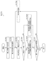
- FIG. 1 is a diagram showing a configuration of encoded three-dimensional data according to the first embodiment.
- FIG. 2 is a diagram illustrating an example of a prediction structure between SPCs belonging to the lowest layer of the GOS according to the first embodiment.
- FIG. 3 is a diagram illustrating an example of a prediction structure between layers according to the first embodiment.
- FIG. 4 is a diagram illustrating an example of the coding order of GOS according to the first embodiment.
- FIG. 5 is a diagram illustrating an example of the coding order of GOS according to the first embodiment.
- FIG. 6 is a block diagram of the three-dimensional data encoding apparatus according to the first embodiment.
- FIG. 7 is a flowchart of the encoding process according to the first embodiment.
- FIG. 8 is a block diagram of the three-dimensional data decoding apparatus according to the first embodiment.
- FIG. 9 is a flowchart of the decoding process according to the first embodiment.
- FIG. 10 is a diagram illustrating an example of meta information according to the first embodiment.
- FIG. 11 is a diagram illustrating a configuration example of the SWLD according to the second embodiment.
- FIG. 12 is a diagram illustrating an operation example of the server and the client according to the second embodiment.
- FIG. 13 is a diagram illustrating an operation example of the server and the client according to the second embodiment.
- FIG. 14 is a diagram illustrating an operation example of the server and the client according to the second embodiment.
- FIG. 15 is a diagram illustrating an operation example of the server and the client according to the second embodiment.
- FIG. 15 is a diagram illustrating an operation example of the server and the client according to the second embodiment.
- FIG. 16 is a block diagram of a three-dimensional data encoding apparatus according to Embodiment 2.
- FIG. 17 is a flowchart of the encoding process according to the second embodiment.
- FIG. 18 is a block diagram of the 3D data decoding apparatus according to the second embodiment.
- FIG. 19 is a flowchart of the decoding process according to the second embodiment.
- FIG. 20 is a diagram illustrating a configuration example of the WLD according to the second embodiment.
- FIG. 21 is a diagram illustrating an example of a WLD octree structure according to the second embodiment.
- FIG. 22 is a diagram illustrating a configuration example of the SWLD according to the second embodiment.
- FIG. 23 is a diagram illustrating an example of an octree structure of SWLD according to the second embodiment.
- FIG. 24 is a block diagram of the three-dimensional data creation device according to the third embodiment.
- FIG. 25 is a block diagram of the three-dimensional data transmission apparatus according to the third embodiment.
- FIG. 26 is a block diagram of the three-dimensional information processing apparatus according to the fourth embodiment.
- FIG. 27 is a block diagram of the three-dimensional data creation device according to the fifth embodiment.
- FIG. 28 is a diagram illustrating a configuration of a system according to the sixth embodiment.
- FIG. 29 is a block diagram of a client device according to the sixth embodiment.
- FIG. 30 is a block diagram of a server according to the sixth embodiment.
- FIG. 31 is a flowchart of three-dimensional data creation processing by the client device according to the sixth embodiment.
- FIG. 32 is a flowchart of sensor information transmission processing by the client device according to the sixth embodiment.
- FIG. 33 is a flowchart of three-dimensional data creation processing by the server according to the sixth embodiment.
- FIG. 34 is a flowchart of the three-dimensional map transmission process by the server according to the sixth embodiment.
- FIG. 35 is a diagram illustrating a configuration of a modified example of the system according to the sixth embodiment.
- FIG. 36 is a diagram illustrating configurations of a server and a client device according to the sixth embodiment.
- FIG. 37 is a block diagram of the three-dimensional data encoding apparatus according to the seventh embodiment.
- FIG. 38 is a diagram illustrating an example of the prediction residual according to the seventh embodiment.
- FIG. 39 is a diagram illustrating an example of a volume according to the seventh embodiment.
- FIG. 40 is a diagram illustrating an example of an octree representation of a volume according to the seventh embodiment.
- FIG. 41 is a diagram illustrating an example of a bit string of a volume according to the seventh embodiment.
- FIG. 42 is a diagram illustrating an example of an octree representation of a volume according to the seventh embodiment.
- FIG. 43 is a diagram illustrating an example of a volume according to the seventh embodiment.
- FIG. 44 is a diagram for describing intra prediction processing according to the seventh embodiment.
- FIG. 45 is a diagram for explaining rotation and translation processing according to the seventh embodiment.
- FIG. 46 is a diagram illustrating a syntax example of the RT application flag and the RT information according to the seventh embodiment.
- FIG. 47 is a diagram for explaining inter prediction processing according to Embodiment 7.
- FIG. 48 is a block diagram of the three-dimensional data decoding apparatus according to the seventh embodiment.
- FIG. 49 is a flowchart of three-dimensional data encoding processing by the three-dimensional data encoding device according to Embodiment 7.
- FIG. 50 is a flowchart of the 3D data decoding process performed by the 3D data decoding apparatus according to the seventh embodiment.
- FIG. 51 is a diagram illustrating a configuration of a distribution system according to the eighth embodiment.
- FIG. 52 is a diagram illustrating a configuration example of a bit stream of an encoded 3D map according to the eighth embodiment.
- FIG. 53 is a diagram for explaining the improvement effect of the coding efficiency according to the eighth embodiment.
- FIG. 54 is a flowchart of processing by the server according to Embodiment 8.
- FIG. 54 is a flowchart of processing by the server according to Embodiment 8.
- FIG. 55 is a flowchart of processing by a client according to the eighth embodiment.
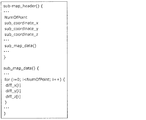
- FIG. 56 is a diagram illustrating a syntax example of a submap according to the eighth embodiment.
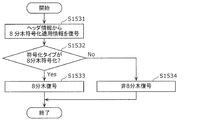
- FIG. 57 is a diagram schematically illustrating a coding type switching process according to the eighth embodiment.
- FIG. 58 is a diagram illustrating a syntax example of a submap according to the eighth embodiment.
- FIG. 59 is a flowchart of the three-dimensional data encoding process according to the eighth embodiment.
- FIG. 60 is a flowchart of the three-dimensional data decoding process according to the eighth embodiment.
- FIG. 61 is a diagram schematically illustrating an operation of a modification of the coding type switching process according to the eighth embodiment.
- FIG. 62 is a diagram schematically illustrating an operation of a modification of the coding type switching process according to the eighth embodiment.
- FIG. 63 is a diagram schematically illustrating an operation of a modification of the coding type switching process according to the eighth embodiment.
- FIG. 64 is a diagram schematically illustrating an operation of a modification of the difference value calculation process according to the eighth embodiment.
- FIG. 65 is a diagram schematically illustrating an operation of a modification of the difference value calculation process according to the eighth embodiment.
- FIG. 66 is a diagram schematically illustrating an operation of a modification of the difference value calculation process according to the eighth embodiment.
- FIG. 67 is a diagram schematically illustrating an operation of a modification of the difference value calculation process according to the eighth embodiment.
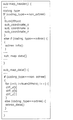
- FIG. 68 is a diagram showing a syntax example of a volume according to the eighth embodiment.
- FIG. 69 is a diagram illustrating an example of an important region according to the ninth embodiment.
- FIG. 70 is a diagram illustrating an example of an occupancy code according to the ninth embodiment.
- FIG. 71 is a diagram illustrating an example of a quadtree structure according to the ninth embodiment.
- FIG. 72 is a diagram illustrating an example of an occupancy code and a location code according to the ninth embodiment.
- FIG. 73 is a diagram illustrating an example of a three-dimensional point obtained by LiDAR according to the ninth embodiment.
- FIG. 74 is a diagram illustrating an example of an octree structure according to the ninth embodiment.
- FIG. 75 is a diagram illustrating an example of mixed coding according to Embodiment 9.
- FIG. 76 is a diagram for explaining a method of switching between location coding and occupancy coding according to Embodiment 9.
- FIG. 77 is a diagram illustrating an example of a bit stream for location coding according to the ninth embodiment.
- FIG. 78 is a diagram illustrating an example of a mixed coding bitstream according to the ninth embodiment.
- FIG. 79 is a diagram showing a tree structure of an important three-dimensional point occupancy code according to the ninth embodiment.
- FIG. 80 is a diagram showing a tree structure of occupancy codes of non-important 3D points according to Embodiment 9.
- FIG. 81 is a diagram illustrating an example of a mixed-encoding bitstream according to the ninth embodiment.
- FIG. 82 is a diagram illustrating an example of a bitstream including coding mode information according to Embodiment 9.
- FIG. 83 is a diagram illustrating a syntax example according to the ninth embodiment.
- FIG. 84 is a flowchart of the encoding process according to the ninth embodiment.
- FIG. 85 is a flowchart of node encoding processing according to the ninth embodiment.
- FIG. 86 is a flowchart of decoding processing according to Embodiment 9.
- FIG. 87 is a flowchart of node decoding processing according to the ninth embodiment.
- FIG. 88 is a diagram illustrating an example of a tree structure according to the tenth embodiment.
- FIG. 89 is a diagram illustrating an example of the number of effective leaves included in each branch according to the tenth embodiment.
- FIG. 90 is a diagram illustrating an example of application of the coding scheme according to Embodiment 10.
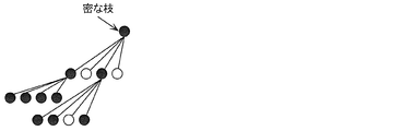
- FIG. 91 is a diagram illustrating an example of a dense branch region according to the tenth embodiment.
- FIG. 92 is a diagram showing an example of a dense three-dimensional point group according to the tenth embodiment.
- FIG. 93 is a diagram showing an example of a sparse three-dimensional point group according to the tenth embodiment.
- FIG. 94 is a flowchart of the encoding process according to the tenth embodiment.
- FIG. 95 is a flowchart of decoding processing according to Embodiment 10.
- FIG. 96 is a flowchart of the encoding process according to the tenth embodiment.
- FIG. 97 is a flowchart of decoding processing according to the tenth embodiment.
- FIG. 98 is a flowchart of the encoding process according to the tenth embodiment.
- FIG. 99 is a flowchart of decoding processing according to the tenth embodiment.
- FIG. 100 is a flowchart of three-dimensional point separation processing according to the tenth embodiment.
- FIG. 101 is a diagram illustrating a syntax example according to the tenth embodiment.
- FIG. 102 is a diagram illustrating an example of dense branches according to the tenth embodiment.
- FIG. 103 is a diagram illustrating an example of sparse branches according to the tenth embodiment.
- FIG. 104 is a flowchart of the encoding process according to the modification of the tenth embodiment.
- FIG. 105 is a flowchart of decoding processing according to a modification of the tenth embodiment.
- FIG. 106 is a flowchart of three-dimensional point separation processing according to a modification of the tenth embodiment.
- FIG. 107 is a diagram illustrating a syntax example according to a modification of the tenth embodiment.
- FIG. 108 is a flowchart of the encoding process according to the tenth embodiment.
- FIG. 109 is a flowchart of decoding processing according to Embodiment 10.
- FIG. 110 is a diagram illustrating an example of a tree structure according to the eleventh embodiment.
- FIG. 111 is a diagram illustrating an example of an occupancy code according to the eleventh embodiment.
- FIG. 112 is a diagram schematically illustrating an operation of the three-dimensional data encoding device according to the eleventh embodiment.
- FIG. 113 is a diagram showing an example of the geometric information according to the eleventh embodiment.
- FIG. 114 is a diagram illustrating an example of selecting an encoding table using geometric information according to Embodiment 11.
- FIG. 115 is a diagram showing a selection example of the coding table using the structure information according to the eleventh embodiment.
- FIG. 116 is a diagram illustrating an example of selecting an encoding table using attribute information according to Embodiment 11.
- FIG. 117 is a diagram illustrating an example of selecting an encoding table using attribute information according to the eleventh embodiment.
- FIG. 118 is a diagram illustrating a configuration example of a bit stream according to the eleventh embodiment.
- FIG. 119 is a diagram illustrating an example of an encoding table according to Embodiment 11.
- 120 is a diagram illustrating an example of an encoding table according to Embodiment 11.
- FIG. 121 is a diagram illustrating a configuration example of a bitstream according to the eleventh embodiment.
- FIG. 122 is a diagram illustrating an example of an encoding table according to Embodiment 11.
- FIG. 123 is a diagram illustrating an example of an encoding table according to Embodiment 11.
- FIG. 124 is a diagram illustrating an example of the bit number of the occupancy code according to the eleventh embodiment.
- FIG. 125 is a flowchart of an encoding process using geometric information according to Embodiment 11.
- FIG. 126 is a flowchart of decoding processing using geometric information according to Embodiment 11.
- FIG. 127 is a flowchart of the encoding process using the structure information according to the eleventh embodiment.
- FIG. 128 is a flowchart of decoding processing using structure information according to Embodiment 11.
- FIG. 129 is a flowchart of encoding processing using attribute information according to Embodiment 11.
- FIG. 130 is a flowchart of decoding processing using attribute information according to Embodiment 11.
- FIG. 131 is a flowchart of a coding table selection process using geometric information according to Embodiment 11.
- FIG. 132 is a flowchart of a coding table selection process using structure information according to Embodiment 11.
- FIG. 133 is a flowchart of an encoding table selection process using attribute information according to Embodiment 11.
- FIG. 134 is a block diagram of a 3D data encoding apparatus according to Embodiment 11.
- FIG. 135 is a block diagram of the 3D data decoding apparatus according to Embodiment 11.
- FIG. FIG. 136 is a diagram illustrating a reference relationship in the octree structure according to the twelfth embodiment.
- FIG. 137 is a diagram showing a reference relationship in the space area according to the twelfth embodiment.
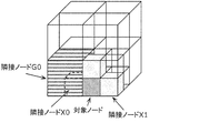
- 138 is a diagram illustrating an example of adjacent reference nodes according to Embodiment 12.
- FIG. FIG. 139 is a diagram illustrating a relationship between a parent node and a node according to the twelfth embodiment.
- FIG. 140 is a diagram illustrating an example of the occupancy code of the parent node according to the twelfth embodiment.
- FIG. 141 is a block diagram of a 3D data encoding apparatus according to Embodiment 12.
- FIG. 142 is a block diagram of a 3D data decoding apparatus according to Embodiment 12.
- FIG. 143 is a flowchart of 3D data encoding processing according to Embodiment 12.
- FIG. 144 is a flowchart of the three-dimensional data decoding process according to the twelfth embodiment.
- FIG. 145 is a diagram illustrating an example of coding table switching according to the twelfth embodiment.
- FIG. 146 is a diagram illustrating a reference relationship in the space area according to the first modification of the twelfth embodiment.
- FIG. 147 is a diagram illustrating a syntax example of the header information according to the first modification of the twelfth embodiment.
- FIG. 148 is a diagram illustrating a syntax example of the header information according to the first modification of the twelfth embodiment.
- FIG. 149 is a diagram illustrating an example of adjacent reference nodes according to the second modification of the twelfth embodiment.
- FIG. 150 is a diagram illustrating examples of target nodes and adjacent nodes according to the second modification of the twelfth embodiment.
- FIG. 151 is a diagram showing a reference relationship in the octree structure according to the third modification of the twelfth embodiment.
- FIG. 152 is a diagram showing a reference relationship in the space area according to the third modification of the twelfth embodiment.
- FIG. 153 is a diagram illustrating a syntax example of the header information according to Embodiment 13.
- FIG. 154 is a diagram illustrating a configuration example of an octree when the mode information is 1 according to the thirteenth embodiment.
- FIG. 155 is a diagram illustrating a configuration example of an octree when the mode information according to Embodiment 13 is 0.
- FIG. 156 is a diagram illustrating a syntax example of node information according to the thirteenth embodiment.
- FIG. 157 is a flowchart of 3D data encoding processing according to Embodiment 13.
- FIG. 158 is a flowchart of three-dimensional data decoding processing according to Embodiment 13.
- FIG. 159 is a block diagram of a 3D data encoding apparatus according to Embodiment 13.
- FIG. 160 is a block diagram of a 3D data decoding apparatus according to Embodiment 13.
- FIG. 161 is a flowchart of 3D data encoding processing according to Embodiment 13.
- FIG. 162 is a flowchart of the three-dimensional data decoding process according to the thirteenth embodiment.
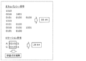
- FIG. 163 is a diagram illustrating an example of 1-bit occupation positions and remaining bits according to the fourteenth embodiment.
- FIG. 164 is a diagram for describing processing for determining whether or not to use the occupied position coding according to the fourteenth embodiment.
- FIG. 165 is a diagram illustrating a syntax example of node information according to the fourteenth embodiment.
- FIG. 166 is a flowchart of 3D data encoding processing according to Embodiment 14.
- FIG. 167 is a flowchart of the occupied position encoding process according to Embodiment 14.
- FIG. 168 is a flowchart of three-dimensional data decoding processing according to Embodiment 14.
- FIG. 169 is a flowchart of the occupied position decoding process according to the fourteenth embodiment.
- FIG. 170 is a block diagram of a 3D data encoding apparatus according to Embodiment 14.
- FIG. 171 is a block diagram of a 3D data decoding apparatus according to Embodiment 14.
- FIG. 172 is a flowchart of three-dimensional data encoding processing according to Embodiment 14.
- FIG. 173 is a flowchart of three-dimensional data decoding processing according to Embodiment 14.
- FIG. 174 is a diagram for explaining overlapping points according to the fifteenth embodiment.
- FIG. 175 is a diagram for explaining processing for overlapping points according to the fifteenth embodiment.
- FIG. 176 is a diagram illustrating a syntax example of the header information according to Embodiment 15.
- FIG. 177 is a diagram illustrating a syntax example of node information according to the fifteenth embodiment.
- FIG. 178 is a flowchart of 3D data encoding processing according to Embodiment 15.
- FIG. 179 is a flowchart of 3D data encoding processing according to Embodiment 15.
- FIG. 180 is a flowchart of the three-dimensional data decoding process according to the fifteenth embodiment.
- FIG. 181 is a block diagram of a 3D data encoding apparatus according to Embodiment 15.
- FIG. 182 is a block diagram of the three-dimensional data decoding apparatus according to the fifteenth embodiment.
- FIG. 183 is a flowchart of a modification of the 3D data encoding process according to Embodiment 15.
- FIG. 184 is a diagram illustrating an example of an occupied state of adjacent nodes according to the sixteenth embodiment.
- FIG. 185 is a diagram illustrating examples of normal node patterns and early termination node patterns of adjacent nodes according to the sixteenth embodiment.
- FIG. 186 is a diagram illustrating an example of normal node patterns of adjacent nodes according to the sixteenth embodiment.
- FIG. 187 is a diagram illustrating an example of normal node patterns of adjacent nodes according to the sixteenth embodiment.
- FIG. 188 is a diagram illustrating an example of adjacent nodes in the octree structure according to Embodiment 16.
- FIG. 189 is a diagram illustrating an example of adjacent nodes according to the sixteenth embodiment.
- 190 is a block diagram of a 3D data encoding apparatus according to Embodiment 16.
- FIG. FIG. 191 is a block diagram of the three-dimensional data decoding apparatus according to the sixteenth embodiment.
- FIG. 192 is a flowchart of three-dimensional data encoding processing according to Embodiment 16.
- FIG. 192 is a flowchart of three-dimensional data encoding processing according to Embodiment 16.
- FIG. 16 is a flowchart of three-dimensional data encoding processing according to Embodiment 16.
- FIG. 193 is a flowchart of three-dimensional data decoding processing according to Embodiment 16.
- FIG. 194 is a flowchart of three-dimensional data encoding processing according to Embodiment 16.
- FIG. 195 is a flowchart of the three-dimensional data decoding process according to the sixteenth embodiment.
- the three-dimensional data encoding method is information on a target node included in a N (N is an integer of 2 or more) branch tree structure of a plurality of three-dimensional points included in three-dimensional data, Generating a bit string including N-bit information indicating whether or not a three-dimensional point exists in each of the child nodes belonging to the target node, and (i) when the bit string is scanned in a predetermined scanning order, Generating position information indicating a head position which is a position in the bit string in which a predetermined code first appears, and (ii) generating a remaining bit which is a bit string after the head position in the scanning order in the bit string.
- the position information and the remaining bits are encoded as information on the target node.
- the three-dimensional data encoding method can improve the encoding efficiency.
- the predetermined code may be 1.
- it has a first mode for encoding the position information and the remaining bits, and a second mode for encoding the bit string, and whether or not a three-dimensional point is included in a peripheral node of the target node. Based on this, one of the first mode and the second mode may be selected.
- the 3D data encoding method can improve the encoding efficiency by selecting a mode according to the state of surrounding 3D points.
- the first mode is selected, and the number or ratio is lower than the threshold. If there are many, the second mode may be selected.
- one of the first mode and the second mode may be selected based on the bit string of the parent node of the target node.
- the first mode when the number of child nodes having a three-dimensional point among the child nodes belonging to the parent node indicated by the bit string of the parent node is less than a predetermined threshold, the first mode is selected, and the number When the value is larger than the threshold value, the second mode may be selected.
- a 3D data decoding method is information on target nodes included in a N (N is an integer of 2 or more) branch tree structure of a plurality of 3D points included in 3D data, i) When a bit string including N-bit information indicating whether or not a three-dimensional point exists in each of the child nodes belonging to the target node is scanned in a predetermined scanning order, a predetermined code is first Position information indicating a head position that is a position in the bit string appearing in (ii), and (ii) a remaining bit that is a bit string after the head position in the scanning order in the bit sequence is decoded from the bit stream, and the position The bit string of the target node is restored from the information and the remaining bits, and the N-ary tree structure is restored using the bit string.
- the three-dimensional data decoding method can improve the encoding efficiency.
- the predetermined code may be 1.
- the first mode for decoding the position information and the remaining bits from the bitstream
- a second mode for decoding the bit string from the bitstream.
- One of the first mode and the second mode may be selected based on whether it is included.
- the 3D data decoding method can improve the encoding efficiency by selecting a mode corresponding to the state of the surrounding 3D points.
- the first mode is selected, and the number or ratio is lower than the threshold. If there are many, the second mode may be selected.
- one of the first mode and the second mode may be selected based on the bit string of the parent node of the target node.
- the first mode when the number of child nodes having a three-dimensional point among the child nodes belonging to the parent node indicated by the bit string of the parent node is less than a predetermined threshold, the first mode is selected, and the number When the value is larger than the threshold value, the second mode may be selected.
- a three-dimensional data encoding device includes a memory, and the processor uses the memory to determine N (N is 2 or more) of a plurality of three-dimensional points included in the three-dimensional data.
- N is 2 or more
- the processor uses the memory to determine N (N is 2 or more) of a plurality of three-dimensional points included in the three-dimensional data.
- a remaining bit that is a bit string after the head position in order is generated, and the position information and the remaining bits are encoded as information of the target node.
- the 3D data encoding apparatus can improve the encoding efficiency.
- a 3D data decoding apparatus includes a processor and a memory, and the processor uses the memory to add N (N is a number of 3D points included in the 3D data).
- N is a number of 3D points included in the 3D data.
- Information of target nodes included in the branch tree structure and (i) a bit string including N-bit information indicating whether or not a three-dimensional point exists in each of the child nodes belonging to the target node Are scanned in a predetermined scanning order, position information indicating a head position that is a position in the bit string in which a predetermined code first appears, and (ii) the head in the scanning order of the bit string
- the 3D data decoding apparatus can improve the encoding efficiency.
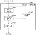
- FIG. 1 is a diagram showing a configuration of encoded three-dimensional data according to the present embodiment.
- the three-dimensional space is divided into spaces (SPC) corresponding to pictures in coding of moving images, and three-dimensional data is coded in units of spaces.
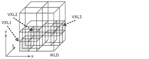
- the space is further divided into volumes (VLM) corresponding to macroblocks or the like in video encoding, and prediction and conversion are performed in units of VLM.
- the volume includes a plurality of voxels (VXL) that are minimum units with which position coordinates are associated.
- prediction is similar to the prediction performed in a two-dimensional image, refers to other processing units, generates predicted three-dimensional data similar to the processing unit to be processed, and generates the predicted three-dimensional data and the processing target.
- the difference from the processing unit is encoded.
- This prediction includes not only spatial prediction that refers to other prediction units at the same time but also temporal prediction that refers to prediction units at different times.
- a three-dimensional data encoding device (hereinafter also referred to as an encoding device) encodes a three-dimensional space represented by point cloud data such as a point cloud
- a point cloud is selected according to the voxel size. Or a plurality of points included in a voxel are collectively encoded. If the voxel is subdivided, the three-dimensional shape of the point cloud can be expressed with high accuracy, and if the voxel size is increased, the three-dimensional shape of the point cloud can be roughly expressed.
- the three-dimensional data is a point cloud
- the three-dimensional data is not limited to the point cloud, and may be three-dimensional data in an arbitrary format.
- hierarchical voxels may be used.
- n-th layer it may be indicated in order whether or not the sample points are present in the n-1 and lower layers (lower layers of the n-th layer). For example, when decoding only the n-th layer, if there is a sample point in the (n ⁇ 1) th or lower layer, it can be decoded assuming that the sample point exists at the center of the voxel in the n-th layer.
- the encoding apparatus acquires point cloud data using a distance sensor, a stereo camera, a monocular camera, a gyroscope, an inertial sensor, or the like.
- Spaces can be decoded independently, such as intra-space (I-SPC), predictive space (P-SPC) that can only be unidirectionally referenced, and bi-directional references. Classified into any one of at least three prediction structures including a large bi-directional space (B-SPC).
- the space has two types of time information, a decoding time and a display time.
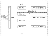
- GOS Group Of Space
- WLD world
- the space area occupied by the world is associated with the absolute position on the earth by GPS or latitude and longitude information. This position information is stored as meta information.
- the meta information may be included in the encoded data or may be transmitted separately from the encoded data.
- all SPCs may be adjacent three-dimensionally, or there may be SPCs that are not three-dimensionally adjacent to other SPCs.
- processing such as encoding, decoding, or referring to three-dimensional data included in a processing unit such as GOS, SPC, or VLM is also simply referred to as encoding, decoding, or referencing the processing unit.
- the three-dimensional data included in the processing unit includes at least one set of a spatial position such as three-dimensional coordinates and a characteristic value such as color information.
- a plurality of SPCs in the same GOS or a plurality of VLMs in the same SPC occupy different spaces, but have the same time information (decoding time and display time).
- the first SPC in the decoding order in GOS is I-SPC.
- GOS There are two types of GOS: closed GOS and open GOS.
- the closed GOS is a GOS that can decode all SPCs in the GOS when decoding is started from the head I-SPC.
- the open GOS some SPCs whose display time is earlier than the first I-SPC in the GOS refer to different GOS, and decoding cannot be performed only by the GOS.
- WLD may be decoded from the reverse direction to the encoding order, and reverse reproduction is difficult if there is a dependency between GOS. Therefore, in such a case, a closed GOS is basically used.
- GOS has a layer structure in the height direction, and encoding or decoding is performed in order from the SPC of the lower layer.
- FIG. 2 is a diagram showing an example of a prediction structure between SPCs belonging to the lowest layer of GOS.
- FIG. 3 is a diagram illustrating an example of a prediction structure between layers.
- I-SPCs there are one or more I-SPCs in GOS.
- objects such as humans, animals, cars, bicycles, traffic lights, and buildings that are landmarks in the three-dimensional space, but it is particularly effective to encode an object having a small size as I-SPC.
- a three-dimensional data decoding device (hereinafter also referred to as a decoding device) decodes only the I-SPC in the GOS when decoding the GOS with a low throughput or high speed.
- the encoding device may switch the encoding interval or appearance frequency of the I-SPC according to the density of the objects in the WLD.
- the encoding device or the decoding device encodes or decodes a plurality of layers in order from the lower layer (layer 1). Thereby, for example, the priority of data near the ground with a larger amount of information can be increased for an autonomous vehicle or the like.
- encoded data used in a drone or the like may be encoded or decoded in order from the SPC of the upper layer in the height direction in the GOS.
- the encoding device or decoding device may encode or decode a plurality of layers so that the decoding device can roughly grasp GOS and gradually increase the resolution.
- the encoding device or the decoding device may encode or decode in the order of layers 3, 8, 1, 9.
- static objects or scenes such as buildings or roads
- dynamic objects such as cars or humans
- Object detection is performed separately by extracting feature points from point cloud data or camera images such as a stereo camera.
- the first method is a method of encoding without distinguishing between static objects and dynamic objects.
- the second method is a method of discriminating between static objects and dynamic objects based on identification information.
- GOS is used as the identification unit.
- the GOS including the SPC configuring the static object and the GOS including the SPC configuring the dynamic object are distinguished by the identification information stored in the encoded data or separately from the encoded data.
- SPC may be used as an identification unit.
- the SPC that includes the VLM that configures the static object and the SPC that includes the VLM that configures the dynamic object are distinguished by the identification information.
- VLM or VXL may be used as the identification unit.
- a VLM or VXL including a static object and a VLM or VXL including a dynamic object are distinguished by the identification information.
- the encoding device may encode the dynamic object as one or more VLMs or SPCs, and may encode the VLM or SPC including the static object and the SPC including the dynamic object as different GOSs. Also, when the GOS size is variable according to the size of the dynamic object, the encoding apparatus separately stores the GOS size as meta information.
- the encoding device may encode the static object and the dynamic object independently of each other and superimpose the dynamic object on the world composed of the static objects.
- the dynamic object is composed of one or more SPCs, and each SPC is associated with one or more SPCs constituting a static object on which the SPC is superimposed.
- a dynamic object may be represented by one or more VLMs or VXLs instead of SPCs.
- the encoding device may encode the static object and the dynamic object as different streams.
- the encoding device may generate a GOS including one or more SPCs that constitute a dynamic object. Further, the encoding apparatus may set the GOS (GOS_M) including the dynamic object and the GOS of the static object corresponding to the GOS_M space area to the same size (occupy the same space area). Thereby, a superimposition process can be performed per GOS.
- GOS including one or more SPCs that constitute a dynamic object.
- the encoding apparatus may set the GOS (GOS_M) including the dynamic object and the GOS of the static object corresponding to the GOS_M space area to the same size (occupy the same space area). Thereby, a superimposition process can be performed per GOS.
- the P-SPC or B-SPC constituting the dynamic object may refer to the SPC included in a different encoded GOS.
- the reference across the GOS is effective from the viewpoint of the compression rate.
- the first method and the second method may be switched according to the use of the encoded data. For example, when using encoded 3D data as a map, it is desirable to be able to separate dynamic objects, and therefore the encoding apparatus uses the second method. On the other hand, the encoding apparatus uses the first method when it is not necessary to separate dynamic objects when encoding three-dimensional data of events such as concerts or sports.
- the GOS or SPC decoding time and display time can be stored in the encoded data or as meta information. Moreover, all the time information of static objects may be the same. At this time, the actual decoding time and display time may be determined by the decoding device. Alternatively, a different value may be given as the decoding time for each GOS or SPC, and the same value may be given as the display time. Furthermore, like a decoder model in moving picture coding such as HEVC's HRD (Hypothetical Reference Decoder), the decoder has a buffer of a predetermined size and can be decoded without failure if a bit stream is read at a predetermined bit rate according to the decoding time. You may introduce a model that guarantees
- the coordinates of the three-dimensional space in the world are expressed by three coordinate axes (x axis, y axis, z axis) orthogonal to each other.
- encoding can be performed so that spatially adjacent GOSs are continuous in the encoded data.
- GOS in the xz plane is continuously encoded.
- the value of the y-axis is updated after encoding of all GOSs in a certain xz plane is completed. That is, as encoding progresses, the world extends in the y-axis direction.
- the GOS index number is set in the encoding order.
- the three-dimensional space of the world is associated with GPS or geographical absolute coordinates such as latitude and longitude in one-to-one correspondence.
- the three-dimensional space may be expressed by a relative position from a preset reference position.
- the x-axis, y-axis, and z-axis directions in the three-dimensional space are expressed as direction vectors determined based on latitude and longitude, and the direction vectors are stored as meta information together with the encoded data.
- the GOS size is fixed, and the encoding device stores the size as meta information. Further, the size of the GOS may be switched depending on, for example, whether it is an urban area or whether it is indoor or outdoor. That is, the size of the GOS may be switched according to the amount or nature of the object that is valuable as information. Alternatively, the encoding device may adaptively switch the GOS size or the I-SPC interval in the GOS in accordance with the object density or the like in the same world. For example, the higher the object density, the smaller the size of the GOS and the shorter the I-SPC interval in the GOS.
- the density of objects is high, so that the GOS is subdivided in order to realize random access with fine granularity.
- the seventh to tenth GOS exist on the back side of the third to sixth GOS, respectively.
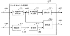
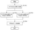
- FIG. 6 is a block diagram of 3D data encoding apparatus 100 according to the present embodiment.
- FIG. 7 is a flowchart showing an operation example of the three-dimensional data encoding apparatus 100.
- the three-dimensional data encoding device 100 shown in FIG. 6 generates encoded three-dimensional data 112 by encoding the three-dimensional data 111.
- the three-dimensional data encoding apparatus 100 includes an acquisition unit 101, an encoding region determination unit 102, a division unit 103, and an encoding unit 104.
- the acquisition unit 101 first acquires three-dimensional data 111 that is point cloud data (S101).
- the coding area determination unit 102 determines a coding target area among the spatial areas corresponding to the acquired point cloud data (S102). For example, the coding area determination unit 102 determines a space area around the position as a coding target area according to the position of the user or the vehicle.
- the dividing unit 103 divides the point cloud data included in the encoding target area into each processing unit.
- the processing unit is the above-described GOS, SPC, or the like.
- this encoding target area corresponds to the above-described world, for example.
- the dividing unit 103 divides the point cloud data into processing units based on a preset GOS size or the presence or size of a dynamic object (S103). Further, the dividing unit 103 determines the start position of the SPC that is the head in the encoding order in each GOS.
- the encoding unit 104 generates encoded three-dimensional data 112 by sequentially encoding a plurality of SPCs in each GOS (S104).
- the three-dimensional data encoding device 100 generates the encoded three-dimensional data 112 by encoding the three-dimensional data 111.
- the 3D data encoding apparatus 100 divides 3D data into first processing units (GOS) each of which is a random access unit and is associated with 3D coordinates.
- the processing unit (GOS) is divided into a plurality of second processing units (SPC), and the second processing unit (SPC) is divided into a plurality of third processing units (VLM).
- the third processing unit (VLM) includes one or more voxels (VXL) that are minimum units with which position information is associated.
- the three-dimensional data encoding device 100 generates encoded three-dimensional data 112 by encoding each of the plurality of first processing units (GOS). Specifically, the three-dimensional data encoding device 100 encodes each of the plurality of second processing units (SPC) in each first processing unit (GOS). In addition, the 3D data encoding apparatus 100 encodes each of the plurality of third processing units (VLM) in each second processing unit (SPC).
- GOS first processing unit
- VLM third processing units
- the 3D data encoding apparatus 100 has the second processing unit to be processed included in the first processing unit (GOS) to be processed.
- SPC is encoded with reference to another second processing unit (SPC) included in the first processing unit (GOS) to be processed. That is, the 3D data encoding apparatus 100 does not refer to the second processing unit (SPC) included in the first processing unit (GOS) different from the first processing unit (GOS) to be processed.
- the processing target second processing unit (SPC) included in the processing target first processing unit (GOS) is set as the processing target first processing unit (GOS).
- the 3D data encoding apparatus 100 uses the first type (I-SPC) that does not refer to another second processing unit (SPC) as the type of the second processing unit (SPC) to be processed, Select either the second type (P-SPC) that refers to the second processing unit (SPC) or the third type that refers to the other two second processing units (SPC), and process according to the selected type
- the target second processing unit (SPC) is encoded.
- FIG. 8 is a block diagram of a block of 3D data decoding apparatus 200 according to the present embodiment.
- FIG. 9 is a flowchart showing an operation example of the three-dimensional data decoding apparatus 200.
- the 3D data decoding apparatus 200 shown in FIG. 8 generates decoded 3D data 212 by decoding the encoded 3D data 211.
- the encoded three-dimensional data 211 is, for example, the encoded three-dimensional data 112 generated by the three-dimensional data encoding device 100.
- the three-dimensional data decoding apparatus 200 includes an acquisition unit 201, a decoding start GOS determination unit 202, a decoding SPC determination unit 203, and a decoding unit 204.
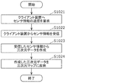
- the acquisition unit 201 acquires the encoded three-dimensional data 211 (S201).
- the decoding start GOS determination unit 202 determines a GOS to be decoded (S202). Specifically, the decoding start GOS determination unit 202 refers to the meta information stored in the encoded 3D data 211 or separately from the encoded 3D data, and the spatial position, object, or The GOS including the SPC corresponding to the time is determined as the GOS to be decrypted.
- the decoding SPC determination unit 203 determines the type (I, P, B) of SPC to be decoded in the GOS (S203). For example, the decoding SPC determination unit 203 determines whether (1) only I-SPC is decoded, (2) I-SPC and P-SPC are decoded, or (3) all types are decoded. Note that this step may not be performed if the type of SPC to be decoded has been determined in advance, such as decoding all SPCs.
- the decoding unit 204 acquires an address position where the head SPC in the decoding order (same as the coding order) in the GOS starts in the encoded three-dimensional data 211, and the code of the first SPC from the address position.
- the data is acquired, and each SPC is sequentially decoded from the head SPC (S204).
- the address position is stored in meta information or the like.
- the three-dimensional data decoding apparatus 200 decodes the decoded three-dimensional data 212. Specifically, the three-dimensional data decoding apparatus 200 decodes each of the encoded three-dimensional data 211 of the first processing unit (GOS) that is a random access unit and each is associated with a three-dimensional coordinate. Thus, the decoded three-dimensional data 212 of the first processing unit (GOS) is generated. More specifically, the three-dimensional data decoding apparatus 200 decodes each of the plurality of second processing units (SPC) in each first processing unit (GOS). The three-dimensional data decoding apparatus 200 decodes each of the plurality of third processing units (VLM) in each second processing unit (SPC).
- SPC second processing units
- VLM third processing units
- This meta information is generated by the three-dimensional data encoding apparatus 100 and is included in the encoded three-dimensional data 112 (211).
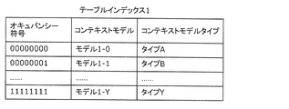
- FIG. 10 is a diagram illustrating an example of a table included in the meta information. Note that not all the tables shown in FIG. 10 need be used, and at least one table may be used.
- the address may be an address in a logical format or a physical address of an HDD or a memory.
- Information specifying a file segment may be used instead of an address.
- a file segment is a unit obtained by segmenting one or more GOSs.
- a plurality of GOSs to which the object belongs may be indicated in the object-GOS table. If the plurality of GOSs are closed GOS, the encoding device and the decoding device can perform encoding or decoding in parallel. On the other hand, if the plurality of GOSs are open GOS, the compression efficiency can be further improved by referring to the plurality of GOSs.
- the 3D data encoding apparatus 100 extracts a feature point specific to an object from a 3D point cloud or the like at the time of world encoding, detects an object based on the feature point, and detects the detected object as a random access point. Can be set as
- the three-dimensional data encoding apparatus 100 includes the first information indicating the plurality of first processing units (GOS) and the three-dimensional coordinates associated with each of the plurality of first processing units (GOS). Is generated. Also, the encoded three-dimensional data 112 (211) includes this first information. The first information further indicates at least one of the object, the time, and the data storage destination associated with each of the plurality of first processing units (GOS).
- the three-dimensional data decoding apparatus 200 acquires the first information from the encoded three-dimensional data 211, and uses the first information to encode the first processing unit corresponding to the specified three-dimensional coordinate, object, or time.
- the original data 211 is specified, and the encoded three-dimensional data 211 is decoded.
- the three-dimensional data encoding apparatus 100 may generate and store the following meta information. Further, the three-dimensional data decoding apparatus 200 may use this meta information at the time of decoding.
- a profile may be defined according to the application, and information indicating the profile may be included in the meta information. For example, profiles for urban areas, suburbs, or flying objects are defined, and the maximum or minimum size of the world, SPC, or VLM is defined in each profile. For example, in a city area, detailed information is required more than in a suburb area, so the minimum size of the VLM is set smaller.
- the meta information may include a tag value indicating the type of object.
- This tag value is associated with the VLM, SPC, or GOS constituting the object. For example, the tag value “0” indicates “person”, the tag value “1” indicates “car”, the tag value “2” indicates “traffic light”, and the like. Also good.
- a tag value indicating a size or a property such as a dynamic object or a static object may be used.
- the meta information may include information indicating the range of the space area occupied by the world.
- the meta information may store the SPC or VXL size as header information common to a plurality of SPCs such as the entire encoded data stream or SPC in GOS.
- the meta information may include identification information such as a distance sensor or a camera used for generating the point cloud, or information indicating the position accuracy of the point cloud in the point cloud.
- the meta information may include information indicating whether the world is composed of only static objects or includes dynamic objects.
- the encoding device or decoding device may encode or decode two or more different SPCs or GOSs in parallel.
- the GOS to be encoded or decoded in parallel can be determined based on meta information indicating the spatial position of the GOS.
- the encoding device or the decoding device uses GPS, route information, zoom magnification, etc. You may encode or decode GOS or SPC included in the space specified based on it.
- the decoding device may perform decoding in order from a space close to the self-position or the travel route.
- the encoding device or the decoding device may encode or decode a space far from its own position or travel route with a lower priority than a close space.
- lowering the priority means lowering the processing order, lowering the resolution (processing by thinning out), or lowering the image quality (increasing encoding efficiency, for example, increasing the quantization step).
- the decoding device may decode only the lower layer when decoding the encoded data that is hierarchically encoded in the space.
- the decoding device may decode preferentially from the lower hierarchy according to the zoom magnification or use of the map.
- the encoding device or the decoding device encodes with a resolution reduced except for an area within a specific height from the road surface (an area for recognition). Or decoding may be performed.
- the encoding device may individually encode the point clouds representing the indoor and outdoor space shapes. For example, by separating GOS (indoor GOS) representing the room and GOS (outdoor GOS) representing the room, the decoding device selects the GOS to be decoded according to the viewpoint position when using the encoded data. it can.
- the encoding device may encode the indoor GOS and the outdoor GOS having close coordinates so as to be adjacent in the encoded stream.
- the encoding apparatus associates both identifiers, and stores information indicating the identifiers associated with each other in the encoded stream or meta information stored separately.
- the decoding apparatus can identify the indoor GOS and the outdoor GOS whose coordinates are close by referring to the information in the meta information.
- the encoding device may switch the size of GOS or SPC between the indoor GOS and the outdoor GOS. For example, the encoding apparatus sets the size of GOS smaller in the room than in the outdoor. Further, the encoding device may change the accuracy when extracting feature points from the point cloud, the accuracy of object detection, or the like between the indoor GOS and the outdoor GOS.
- the encoding device may add information for the decoding device to display the dynamic object separately from the static object to the encoded data.
- the decoding apparatus can display a dynamic object and a red frame or explanatory characters together.
- the decoding device may display only a red frame or explanatory characters instead of the dynamic object.
- the decoding device may display a finer object type. For example, a red frame may be used for a car and a yellow frame may be used for a human.
- the encoding device or the decoding device encodes the dynamic object and the static object as different SPC or GOS according to the appearance frequency of the dynamic object or the ratio of the static object to the dynamic object. Or you may decide whether to decode. For example, when the appearance frequency or ratio of a dynamic object exceeds a threshold, SPC or GOS in which a dynamic object and a static object are mixed is allowed, and the appearance frequency or ratio of a dynamic object does not exceed the threshold Does not allow SPC or GOS in which dynamic objects and static objects are mixed.
- the encoding device When detecting a dynamic object from the two-dimensional image information of the camera instead of the point cloud, the encoding device separately acquires information for identifying the detection result (such as a frame or a character) and the object position, Such information may be encoded as part of the three-dimensional encoded data. In this case, the decoding device superimposes and displays auxiliary information (frame or character) indicating the dynamic object on the decoding result of the static object.
- auxiliary information frame or character
- the encoding device may change the density of VXL or VLM in the SPC according to the complexity of the shape of the static object. For example, the encoding device sets VXL or VLM more densely as the shape of the static object is more complicated. Further, the encoding apparatus may determine a quantization step or the like when quantizing the spatial position or color information according to the density of VXL or VLM. For example, the encoding apparatus sets the quantization step to be smaller as VXL or VLM is denser.
- the encoding device or decoding device performs space encoding or decoding in units of space having coordinate information.
- the encoding device and the decoding device perform encoding or decoding in units of volume in the space.
- the volume includes a voxel that is a minimum unit with which position information is associated.
- the encoding device and the decoding device associate arbitrary elements using a table in which each element of spatial information including coordinates, objects, time, and the like is associated with a GOP, or a table in which elements are associated with each other. Encoding or decoding.
- the decoding apparatus determines coordinates using the value of the selected element, specifies a volume, voxel, or space from the coordinates, and decodes the space including the volume or voxel or the specified space.
- the encoding device determines a volume, voxel, or space that can be selected by the element by feature point extraction or object recognition, and encodes it as a randomly accessible volume, voxel, or space.
- a space refers to an I-SPC that can be encoded or decoded by the space alone, a P-SPC that is encoded or decoded with reference to any one processed space, and any two processed spaces. Are classified into three types of B-SPC encoded or decoded.
- One or more volumes correspond to static objects or dynamic objects.
- a space including a static object and a space including a dynamic object are encoded or decoded as different GOS. That is, the SPC including the static object and the SPC including the dynamic object are assigned to different GOSs.
- a dynamic object is encoded or decoded for each object, and is associated with one or more spaces including static objects. That is, the plurality of dynamic objects are individually encoded, and the obtained encoded data of the plurality of dynamic objects is associated with the SPC including the static object.
- the encoding device and the decoding device increase the priority of I-SPC in GOS and perform encoding or decoding.
- the encoding apparatus performs encoding so that degradation of I-SPC is reduced (so that original three-dimensional data is reproduced more faithfully after decoding).
- the decoding device decodes only I-SPC, for example.
- the encoding device may perform encoding by changing the frequency of using I-SPC according to the density or number (quantity) of objects in the world. That is, the encoding device changes the frequency of selecting the I-SPC according to the number or density of objects included in the three-dimensional data. For example, the encoding device increases the frequency of using the I space as the objects in the world are denser.
- the encoding apparatus sets random access points in units of GOS, and stores information indicating the space area corresponding to GOS in the header information.
- the encoding device uses, for example, a default value as the GOS space size.
- the encoding device may change the size of the GOS according to the number (amount) or density of objects or dynamic objects. For example, the encoding device reduces the GOS space size as the objects or dynamic objects are denser or more numerous.
- the space or volume includes a feature point group derived using information obtained by a sensor such as a depth sensor, gyroscope, or camera.
- the coordinates of the feature point are set at the center position of the voxel. Further, high accuracy of position information can be realized by subdividing voxels.
- the feature point group is derived using a plurality of pictures.
- the plurality of pictures have at least two types of time information: actual time information and the same time information (for example, encoding time used for rate control) in the plurality of pictures associated with the space.
- encoding or decoding is performed in units of GOS including one or more spaces.
- the encoding device and the decoding device refer to the space in the processed GOS and predict the P space or B space in the processing target GOS.
- the encoding device and the decoding device do not refer to different GOS, and use the processed space in the processing target GOS to predict the P space or B space in the processing target GOS.
- the encoding device and the decoding device transmit or receive the encoded stream in units of world including one or more GOSs.
- GOS has a layer structure in at least one direction in the world, and the encoding device and the decoding device perform encoding or decoding from a lower layer.
- a randomly accessible GOS belongs to the lowest layer.
- GOS belonging to an upper layer refers to GOS belonging to the same layer or lower. That is, GOS includes a plurality of layers that are spatially divided in a predetermined direction and each include one or more SPCs.
- the encoding device and the decoding device encode or decode each SPC with reference to the SPC included in the same layer as the SPC or a layer lower than the SPC.
- the encoding device and the decoding device continuously encode or decode GOS within a world unit including a plurality of GOSs.
- the encoding device and the decoding device write or read information indicating the order (direction) of encoding or decoding as metadata. That is, the encoded data includes information indicating the encoding order of a plurality of GOSs.
- the encoding device and the decoding device encode or decode two or more different spaces or GOS in parallel.
- the encoding device and the decoding device encode or decode space or GOS space information (coordinates, size, etc.).
- the encoding device and the decoding device encode or decode a space or GOS included in a specific space that is specified based on external information related to its position or / and region size, such as GPS, route information, or magnification. .
- the encoding device or decoding device encodes or decodes a space far from its own position with a lower priority than a close space.
- the encoding apparatus sets a certain direction of the world according to the magnification or application, and encodes GOS having a layer structure in the direction. Further, the decoding apparatus preferentially decodes GOS having a layer structure in one direction of the world set according to the magnification or use from the lower layer.
- the encoding device changes the feature point included in the space, the accuracy of object recognition, or the size of the space area between the room and the room.
- the encoding device and the decoding device encode or decode the indoor GOS and the outdoor GOS whose coordinates are close to each other in the world, and encode or decode these identifiers in association with each other.
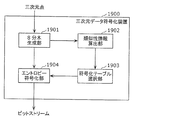
- a three-dimensional data encoding method and a three-dimensional data encoding device for providing a function of transmitting and receiving only necessary information according to applications in encoded data of a three-dimensional point cloud, and A 3D data decoding method and 3D data decoding apparatus for decoding encoded data will be described.
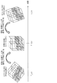
- FIG. 11 is a diagram illustrating a configuration example of a sparse world and a world.
- SWLD includes FGOS, which is a GOS composed of FVXL, FSPC, which is an SPC composed of FVXL, and FVLM, which is a VLM composed of FVXL.
- FGOS which is a GOS composed of FVXL
- FSPC which is an SPC composed of FVXL
- FVLM which is a VLM composed of FVXL.
- the data structure and prediction structure of FGOS, FSPC, and FVLM may be the same as those of GOS, SPC, and VLM.
- the feature amount is a feature amount that expresses VXL three-dimensional position information or visible light information of the VXL position, and is a feature amount that is often detected particularly at corners and edges of a three-dimensional object.
- this feature quantity is a three-dimensional feature quantity or visible light feature quantity as described below, but any other feature quantity that represents VXL position, luminance, color information, or the like can be used. It does n’t matter.
- a SHOT feature value Signature of Histograms of Orientations
- a PFH feature value Point Feature History
- a PPF feature value Point Pair Feature
- the SHOT feature value is obtained by dividing the periphery of the VXL, calculating the inner product of the reference point and the normal vector of the divided area, and generating a histogram.
- This SHOT feature amount has a feature that the number of dimensions is high and the feature expression power is high.
- the PFH feature value is obtained by selecting a large number of two-point sets in the vicinity of the VXL, calculating a normal vector from the two points, and forming a histogram. Since this PFH feature amount is a histogram feature, it has a feature that it has robustness against a certain amount of disturbance and has a high feature expression power.
- the PPF feature value is a feature value calculated using a normal vector or the like for each two VXL points. Since all VXL is used for this PPF feature quantity, it has robustness against occlusion.
- SIFT Scale-Invariant Feature Transform
- SURF Speeded Up Robust Features
- HOG Histogram of Orient
- SWLD is generated by calculating the feature amount from each VXL of WLD and extracting FVXL.
- the SWLD may be updated every time the WLD is updated, or may be updated periodically after a certain period of time regardless of the update timing of the WLD.
- SWLD may be generated for each feature amount. For example, separate SWLDs may be generated for each feature quantity, such as SWLD1 based on SHOT feature quantity and SWLD2 based on SIFT feature quantity, and the SWLD may be used properly according to the application. Further, the calculated feature amount of each FVXL may be held in each FVXL as feature amount information.
- SWLD Sparse World
- the network bandwidth and transfer time can be suppressed by holding WLD and SWLD as map information in a server and switching the map information to be transmitted to WLD or SWLD in response to a request from a client. . Specific examples will be shown below.
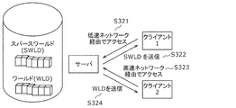
- FIG. 12 and 13 are diagrams showing examples of using SWLD and WLD.
- the client 1 when the client 1 which is an in-vehicle device needs map information for the purpose of self-position determination, the client 1 sends a request for acquiring map data for self-position estimation to the server (S301).
- the server transmits the SWLD to the client 1 in response to the acquisition request (S302).
- the client 1 performs self-position determination using the received SWLD (S303).
- the client 1 acquires VXL information around the client 1 by various methods such as a distance sensor such as a range finder, a stereo camera, or a combination of a plurality of monocular cameras, and self-assembling from the obtained VXL information and SWLD.
- the self-position information includes the three-dimensional position information and orientation of the client 1.
- the client 2 which is an in-vehicle device needs map information for the purpose of drawing a map such as a three-dimensional map
- the client 2 sends a request for obtaining map data for map drawing to the server (S311). ).
- the server transmits a WLD to the client 2 in response to the acquisition request (S312).
- the client 2 performs map drawing using the received WLD (S313).
- the client 2 creates a rendering image using, for example, an image captured by itself with a visible light camera or the like and a WLD acquired from the server, and draws the created image on a screen such as a car navigation system.
- the server sends SWLD to the client for applications that mainly require the feature amount of each VXL such as self-position estimation, and WLD is used when detailed VXL information is required such as map drawing. Send to client. Thereby, it becomes possible to transmit / receive map data efficiently.
- the client may determine whether SWLD or WLD is necessary, and may request the server to send SWLD or WLD. Further, the server may determine whether to transmit SWLD or WLD according to the situation of the client or the network.
- SWLD sparse world
- WLD world
- FIG. 14 is a diagram showing an operation example in this case.
- a low-speed network with a limited network bandwidth such as in LTE (Long Term Evolution) environment
- the client accesses the server via the low-speed network (S321), and maps from the server.
- SWLD is acquired as information (S322).
- a high-speed network with sufficient network bandwidth such as in a Wi-Fi (registered trademark) environment
- the client accesses the server via the high-speed network (S323), and acquires the WLD from the server. (S324).
- the client can acquire suitable map information according to the network bandwidth of the client.
- the client receives the SWLD via LTE outdoors, and acquires the WLD via Wi-Fi (registered trademark) when entering a facility or the like indoors. As a result, the client can acquire more detailed map information indoors.
- Wi-Fi registered trademark
- the client may request WLD or SWLD from the server according to the network bandwidth used by the client.
- the client may transmit information indicating the network bandwidth used by the client to the server, and the server may transmit data (WLD or SWLD) suitable for the client according to the information.
- the server may determine the network bandwidth of the client and transmit data (WLD or SWLD) suitable for the client.
- FIG. 15 is a diagram illustrating an operation example in this case.
- the client when the client is moving at high speed (S331), the client receives SWLD from the server (S332).
- the client receives the WLD from the server (S334).
- the client can acquire map information matching the speed while suppressing the network bandwidth.
- the client can update rough map information at an appropriate speed by receiving a SWLD with a small amount of data while traveling on an expressway.
- the client can acquire more detailed map information by receiving the WLD while traveling on a general road.
- the client may request WLD or SWLD from the server according to its moving speed.
- the client may transmit information indicating its own moving speed to the server, and the server may transmit data (WLD or SWLD) suitable for the client according to the information.
- the server may determine the moving speed of the client and transmit data (WLD or SWLD) suitable for the client.
- the client may first acquire the SWLD from the server, and may acquire the WLD of an important area in the SWLD. For example, when acquiring map data, the client first acquires rough map information by SWLD, narrows down areas where many features such as buildings, signs, or people appear, and then narrows down the WLD of the narrowed area. Get it later. Thereby, the client can acquire detailed information on a necessary area while suppressing the amount of data received from the server.
- the server may create a separate SWLD for each object from the WLD, and the client may receive each according to the application. Thereby, a network band can be suppressed.
- the server recognizes a person or a car in advance from the WLD, and creates a human SWLD and a car SWLD.
- the client receives a person's SWLD if he wants to obtain information on people around him, and receives a car's SWLD if he wants to obtain car information.
- SWLD types may be distinguished by information (flag or type) added to a header or the like.
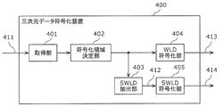
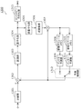
- FIG. 16 is a block diagram of 3D data encoding apparatus 400 according to the present embodiment.
- FIG. 17 is a flowchart of three-dimensional data encoding processing by the three-dimensional data encoding device 400.
- the 16 generates encoded 3D data 413 and 414, which are encoded streams, by encoding the input 3D data 411.
- the encoded 3D data 413 is encoded 3D data corresponding to WLD
- the encoded 3D data 414 is encoded 3D data corresponding to SWLD.
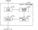
- the three-dimensional data encoding apparatus 400 includes an acquisition unit 401, an encoding region determination unit 402, a SWLD extraction unit 403, a WLD encoding unit 404, and a SWLD encoding unit 405.
- the acquisition unit 401 acquires input three-dimensional data 411 that is point cloud data in a three-dimensional space (S401).
- the coding area determination unit 402 determines a space area to be coded based on the space area where the point cloud data exists (S402).
- the SWLD extraction unit 403 defines a space area to be encoded as WLD, and calculates a feature amount from each VXL included in the WLD. Then, the SWLD extraction unit 403 extracts VXL whose feature amount is equal to or greater than a predetermined threshold, defines the extracted VXL as FVXL, and adds the FVXL to the SWLD, thereby generating extracted three-dimensional data 412. (S403). That is, extracted 3D data 412 having a feature amount equal to or greater than a threshold is extracted from the input 3D data 411.
- the WLD encoding unit 404 generates encoded three-dimensional data 413 corresponding to WLD by encoding the input three-dimensional data 411 corresponding to WLD (S404). At this time, the WLD encoding unit 404 adds information for distinguishing that the encoded three-dimensional data 413 is a stream including WLD to the header of the encoded three-dimensional data 413.
- the SWLD encoding unit 405 generates encoded three-dimensional data 414 corresponding to SWLD by encoding the extracted three-dimensional data 412 corresponding to SWLD (S405). At this time, the SWLD encoding unit 405 adds information for distinguishing that the encoded three-dimensional data 414 is a stream including SWLD to the header of the encoded three-dimensional data 414.
- processing order of the process of generating the encoded three-dimensional data 413 and the process of generating the encoded three-dimensional data 414 may be reverse to the above. Also, some or all of these processes may be performed in parallel.
- a parameter “world_type” is defined.
- a specific flag may be included in one of the encoded three-dimensional data 413 and 414. For example, a flag including that the stream includes SWLD may be assigned to the encoded three-dimensional data 414. In this case, the decoding apparatus can determine whether the stream includes WLD or SWLD depending on the presence or absence of a flag.
- the encoding method used when the WLD encoding unit 404 encodes WLD may be different from the encoding method used when the SWLD encoding unit 405 encodes SWLD.
- inter prediction may be prioritized among intra prediction and inter prediction over the encoding method used for WLD.
- the encoding method used for SWLD and the encoding method used for WLD may differ in the three-dimensional position representation method.
- the three-dimensional position of FVXL may be represented by three-dimensional coordinates
- WLD the three-dimensional position may be represented by an octree that will be described later, and vice versa.
- the SWLD encoding unit 405 performs encoding so that the data size of the encoded three-dimensional data 414 of SWLD is smaller than the data size of the encoded three-dimensional data 413 of WLD.
- SWLD may have a lower correlation between data than WLD.
- the encoding efficiency decreases, and the data size of the encoded three-dimensional data 414 may become larger than the data size of the encoded three-dimensional data 413 of WLD. Therefore, when the data size of the obtained encoded three-dimensional data 414 is larger than the data size of the encoded three-dimensional data 413 of the WLD, the SWLD encoding unit 405 performs re-encoding to thereby obtain the data size.
- the encoded three-dimensional data 414 with reduced is regenerated.
- the SWLD extraction unit 403 regenerates the extracted three-dimensional data 412 in which the number of feature points to be extracted is reduced, and the SWLD encoding unit 405 encodes the extracted three-dimensional data 412.
- the degree of quantization in the SWLD encoding unit 405 may be made coarser.
- the degree of quantization can be roughened by rounding the data in the lowest layer.
- the SWLD encoding unit 405 does not generate the SWLD encoded three-dimensional data 414. May be.
- the encoded 3D data 413 of WLD may be copied to the encoded 3D data 414 of SWLD. That is, the WLD encoded three-dimensional data 413 may be used as it is as the SWLD encoded three-dimensional data 414.
- FIG. 18 is a block diagram of 3D data decoding apparatus 500 according to the present embodiment.
- FIG. 19 is a flowchart of the 3D data decoding process performed by the 3D data decoding apparatus 500.
- the three-dimensional data decoding apparatus 500 shown in FIG. 18 generates decoded three-dimensional data 512 or 513 by decoding the encoded three-dimensional data 511.
- the encoded 3D data 511 is, for example, the encoded 3D data 413 or 414 generated by the 3D data encoding device 400.
- the 3D data decoding apparatus 500 includes an acquisition unit 501, a header analysis unit 502, a WLD decoding unit 503, and a SWLD decoding unit 504.
- the acquisition unit 501 acquires encoded three-dimensional data 511 (S501).
- the header analysis unit 502 analyzes the header of the encoded three-dimensional data 511 and determines whether the encoded three-dimensional data 511 is a stream including WLD or a stream including SWLD (S502). For example, the determination is performed with reference to the above-described parameter of type_type.
- the WLD decoding unit 503 When the encoded 3D data 511 is a stream including WLD (Yes in S503), the WLD decoding unit 503 generates the decoded 3D data 512 of WLD by decoding the encoded 3D data 511 (S504). . On the other hand, when the encoded three-dimensional data 511 is a stream including SWLD (No in S503), the SWLD decoding unit 504 generates the decoded three-dimensional data 513 of SWLD by decoding the encoded three-dimensional data 511 ( S505).
- the decoding method used when the WLD decoding unit 503 decodes WLD may be different from the decoding method used when the SWLD decoding unit 504 decodes SWLD.
- inter prediction may be prioritized among intra prediction and inter prediction over the decoding method used for WLD.
- the three-dimensional position representation method may be different between the decoding method used for SWLD and the decoding method used for WLD.
- the three-dimensional position of FVXL may be represented by three-dimensional coordinates
- WLD the three-dimensional position may be represented by an octree that will be described later, and vice versa.
- FIG. 20 is a diagram illustrating an example of VXL of WLD.
- FIG. 21 is a diagram showing an octree structure of the WLD shown in FIG. In the example shown in FIG. 20, there are three VXLs 1 to 3 that are VXLs including point clouds (hereinafter referred to as effective VXLs).
- the octree structure is composed of nodes and leaves. Each node has a maximum of 8 nodes or leaves. Each leaf has VXL information. Of the leaves shown in FIG. 21, leaves 1, 2, and 3 represent VXL1, VXL2, and VXL3 shown in FIG. 20, respectively.
- each node and leaf corresponds to a three-dimensional position.
- Node 1 corresponds to the entire block shown in FIG.
- the block corresponding to the node 1 is divided into eight blocks. Among the eight blocks, a block including the valid VXL is set as a node, and the other blocks are set as leaves.
- the block corresponding to the node is further divided into eight nodes or leaves, and this process is repeated for the hierarchy of the tree structure. In addition, all the lowermost blocks are set to leaves.
- FIG. 22 is a diagram showing an example of SWLD generated from the WLD shown in FIG. VXL1 and VXL2 shown in FIG. 20 are determined as FVXL1 and FVXL2 as a result of feature amount extraction, and are added to SWLD.
- VXL3 is not determined as FVXL and is not included in SWLD.
- FIG. 23 is a diagram illustrating the octree structure of the SWLD illustrated in FIG. In the octree structure shown in FIG. 23, leaf 3 corresponding to VXL3 shown in FIG. 21 is deleted. As a result, the node 3 shown in FIG. 21 does not have a valid VXL and is changed to a leaf.
- the number of leaves of SWLD is smaller than the number of leaves of WLD, and the encoded three-dimensional data of SWLD is also smaller than the encoded three-dimensional data of WLD.
- a client such as an in-vehicle device receives SWLD from a server when performing self-position estimation, performs self-position estimation using SWLD, and performs obstacle detection when performing distance detection such as a range finder, stereo.
- Obstacle detection may be performed based on surrounding three-dimensional information acquired by using various methods such as a camera or a combination of a plurality of monocular cameras.
- SWLD hardly includes VXL data in a flat region. Therefore, the server may hold a sub-sample world (subWLD) obtained by sub-sampled WLD and send SWLD and subWLD to the client for detection of a static obstacle. Thereby, it is possible to perform self-position estimation and obstacle detection on the client side while suppressing the network bandwidth.
- subWLD sub-sample world
- the server may generate a mesh from WLD and hold it in advance as a mesh world (MWLD). For example, the client receives MWLD if it needs coarse 3D rendering and receives WLD if it needs detailed 3D rendering. Thereby, a network band can be suppressed.
- MWLD mesh world
- the server may calculate the FVXL by a different method. For example, the server determines that VXL, VLM, SPC, or GOS constituting a signal or intersection is necessary for self-position estimation, driving assistance, automatic driving, etc., and includes it in SWLD as FVXL, FVLM, FSPC, FGOS It doesn't matter if you do. Further, the above determination may be made manually. In addition, you may add FVXL etc. which were obtained by the said method to FVXL etc. which were set based on the feature-value. That is, the SWLD extraction unit 403 may further extract data corresponding to an object having a predetermined attribute from the input three-dimensional data 411 as the extracted three-dimensional data 412.
- the server may separately hold FVXL necessary for self-position estimation such as signals or intersections, driving assistance, or automatic driving as an upper layer of SWLD (for example, lane world).
- the server may add an attribute to the VXL in the WLD for each random access unit or every predetermined unit.
- the attribute includes, for example, information indicating whether it is necessary or unnecessary for self-position estimation, or information indicating whether it is important as traffic information such as a signal or an intersection. Further, the attribute may include a correspondence relationship with a Feature (an intersection or a road) in the lane information (GDF: Geographic Data Files, etc.).
- the following method may be used as a WLD or SWLD update method.
- Update information indicating changes in people, construction, or row of trees (for trucks) is uploaded to the server as point clouds or metadata. Based on the upload, the server updates the WLD, and then updates the SWLD using the updated WLD.
- the client may send the 3D information generated by itself to the server together with the update notification. Good.
- the server updates SWLD using WLD. If the SWLD is not updated, the server determines that the WLD itself is old.
- information for distinguishing between WLD and SWLD is added as header information of the encoded stream.
- information for distinguishing between WLD and SWLD is added as header information of the encoded stream.
- information for distinguishing between WLD and SWLD is added as header information of the encoded stream.
- information for distinguishing each may be added to the header information.
- SWLD is composed of FVXL, it may include VXL that is not determined to be FVXL.
- the SWLD may include an adjacent VXL used when calculating the feature amount of the FVXL. Accordingly, even when the feature amount information is not added to each FVXL of the SWLD, the client can calculate the feature amount of the FVXL when receiving the SWLD.
- SWLD may include information for distinguishing whether each VXL is FVXL or VXL.
- the three-dimensional data encoding device 400 extracts the extracted three-dimensional data 412 (second three-dimensional data) whose feature amount is equal to or greater than the threshold from the input three-dimensional data 411 (first three-dimensional data), and extracts the extracted three-dimensional data 412 (second three-dimensional data).
- Encoded three-dimensional data 414 (first encoded three-dimensional data) is generated by encoding the three-dimensional data 412.
- the three-dimensional data encoding device 400 generates encoded three-dimensional data 414 in which data having a feature amount equal to or greater than a threshold value is encoded. Thereby, the amount of data can be reduced as compared with the case where the input three-dimensional data 411 is encoded as it is. Therefore, the three-dimensional data encoding device 400 can reduce the amount of data to be transmitted.
- the three-dimensional data encoding device 400 further generates encoded three-dimensional data 413 (second encoded three-dimensional data) by encoding the input three-dimensional data 411.
- the three-dimensional data encoding device 400 can selectively transmit the encoded three-dimensional data 413 and the encoded three-dimensional data 414, for example, according to the usage.
- the extracted three-dimensional data 412 is encoded by the first encoding method
- the input three-dimensional data 411 is encoded by a second encoding method different from the first encoding method.
- the 3D data encoding apparatus 400 can use encoding methods suitable for the input 3D data 411 and the extracted 3D data 412 respectively.
- inter prediction has priority over intra prediction and inter prediction over the second encoding method.
- the three-dimensional data encoding apparatus 400 can raise the priority of inter prediction with respect to the extracted three-dimensional data 412 in which the correlation between adjacent data tends to be low.
- the first encoding method and the second encoding method differ in the three-dimensional position representation method.
- a three-dimensional position is expressed by an octree
- a three-dimensional position is expressed by a three-dimensional coordinate.
- the three-dimensional data encoding device 400 can use a more suitable three-dimensional position representation method for three-dimensional data having different numbers of data (number of VXL or FVXL).
- At least one of the encoded three-dimensional data 413 and 414 is the encoded three-dimensional data obtained by encoding the input three-dimensional data 411 or the input three-dimensional data 411.
- the identifier which shows whether it is the encoding three-dimensional data obtained by encoding a part of is included. That is, the identifier indicates whether the encoded three-dimensional data is WLD encoded three-dimensional data 413 or SWLD encoded three-dimensional data 414.
- the decoding apparatus can easily determine whether the acquired encoded 3D data is the encoded 3D data 413 or the encoded 3D data 414.
- the three-dimensional data encoding device 400 encodes the extracted three-dimensional data 412 so that the data amount of the encoded three-dimensional data 414 is smaller than the data amount of the encoded three-dimensional data 413.
- the three-dimensional data encoding device 400 can make the data amount of the encoded three-dimensional data 414 smaller than the data amount of the encoded three-dimensional data 413.
- the three-dimensional data encoding device 400 further extracts data corresponding to an object having a predetermined attribute from the input three-dimensional data 411 as the extracted three-dimensional data 412.
- an object having a predetermined attribute is an object necessary for self-position estimation, driving assistance, automatic driving, or the like, such as a signal or an intersection.
- the three-dimensional data encoding device 400 can generate encoded three-dimensional data 414 including data necessary for the decoding device.
- the three-dimensional data encoding device 400 (server) further transmits one of the encoded three-dimensional data 413 and 414 to the client according to the state of the client.
- the three-dimensional data encoding device 400 can transmit appropriate data according to the state of the client.
- the client status includes the communication status (for example, network bandwidth) of the client or the moving speed of the client.
- the three-dimensional data encoding apparatus 400 further transmits one of the encoded three-dimensional data 413 and 414 to the client in response to a request from the client.
- the three-dimensional data encoding device 400 can transmit appropriate data in response to a client request.
- the 3D data decoding apparatus 500 decodes the encoded 3D data 413 or 414 generated by the 3D data encoding apparatus 400.
- the three-dimensional data decoding apparatus 500 performs first decoding on the encoded three-dimensional data 414 obtained by encoding the extracted three-dimensional data 412 whose feature amount extracted from the input three-dimensional data 411 is equal to or greater than a threshold value. Decrypt by method. In addition, the three-dimensional data decoding apparatus 500 decodes the encoded three-dimensional data 413 obtained by encoding the input three-dimensional data 411 by a second decoding method different from the first decoding method.
- the three-dimensional data decoding apparatus 500 selects the encoded three-dimensional data 414 obtained by encoding the data whose feature amount is equal to or greater than the threshold, and the encoded three-dimensional data 413, for example, according to the usage application. Can be received automatically. Thereby, the three-dimensional data decoding apparatus 500 can reduce the amount of data to be transmitted. Further, the three-dimensional data decoding apparatus 500 can use a decoding method suitable for each of the input three-dimensional data 411 and the extracted three-dimensional data 412.
- inter prediction has priority over intra prediction and inter prediction over the second decoding method.
- the three-dimensional data decoding apparatus 500 can raise the priority of inter prediction with respect to the extracted three-dimensional data in which the correlation between adjacent data tends to be low.
- the first decoding method and the second decoding method differ in the three-dimensional position representation method.
- the three-dimensional position is expressed by an octree
- the three-dimensional position is expressed by a three-dimensional coordinate.
- the three-dimensional data decoding apparatus 500 can use a more suitable three-dimensional position expression method for three-dimensional data having different numbers of data (number of VXL or FVXL).
- At least one of the encoded three-dimensional data 413 and 414 is the encoded three-dimensional data obtained by encoding the input three-dimensional data 411 or the input three-dimensional data 411.
- the identifier which shows whether it is the encoding three-dimensional data obtained by encoding a part of is included.
- the three-dimensional data decoding apparatus 500 refers to the identifier to identify the encoded three-dimensional data 413 and 414.
- the 3D data decoding apparatus 500 can easily determine whether the acquired encoded 3D data is the encoded 3D data 413 or the encoded 3D data 414.
- the 3D data decoding apparatus 500 further notifies the server of the state of the client (3D data decoding apparatus 500).
- the three-dimensional data decoding apparatus 500 receives one of the encoded three-dimensional data 413 and 414 transmitted from the server according to the state of the client.
- the 3D data decoding apparatus 500 can receive appropriate data according to the state of the client.
- the client status includes the communication status (for example, network bandwidth) of the client or the moving speed of the client.
- the three-dimensional data decoding apparatus 500 further requests one of the encoded three-dimensional data 413 and 414 from the server, and in response to the request, one of the encoded three-dimensional data 413 and 414 transmitted from the server. Receive.
- the three-dimensional data decoding apparatus 500 can receive appropriate data according to the application.
- FIG. 24 is a block diagram of the three-dimensional data creation device 620 according to the present embodiment.
- the three-dimensional data creation device 620 is included in the host vehicle, for example, by synthesizing the received second three-dimensional data 635 with the first three-dimensional data 632 created by the three-dimensional data creation device 620, thereby making the denser.
- the third 3D data 636 is created.
- the three-dimensional data creation device 620 includes a three-dimensional data creation unit 621, a request range determination unit 622, a search unit 623, a reception unit 624, a decoding unit 625, and a synthesis unit 626.
- the three-dimensional data creation unit 621 creates first three-dimensional data 632 using sensor information 631 detected by a sensor included in the host vehicle.
- the required range determination unit 622 determines a required range that is a three-dimensional space range in which data is insufficient in the generated first three-dimensional data 632.
- the search unit 623 searches for surrounding vehicles that possess the three-dimensional data of the requested range, and transmits requested range information 633 indicating the requested range to the surrounding vehicles specified by the search.
- the receiving unit 624 receives encoded three-dimensional data 634 that is an encoded stream of a requested range from surrounding vehicles (S624).
- the search part 623 may issue a request indiscriminately with respect to all the vehicles existing in the specific range, and may receive the encoded three-dimensional data 634 from a partner who has responded.
- the search unit 623 may send a request to an object such as a traffic light or a sign, not limited to a vehicle, and receive the encoded three-dimensional data 634 from the object.
- the decoding unit 625 acquires the second 3D data 635 by decoding the received encoded 3D data 634.
- the synthesizing unit 626 synthesizes the first three-dimensional data 632 and the second three-dimensional data 635 to create denser third three-dimensional data 636.
- FIG. 25 is a block diagram of the three-dimensional data transmission device 640.
- the three-dimensional data transmission device 640 processes the fifth three-dimensional data 652 included in the surrounding vehicle described above and created by the surrounding vehicle into the sixth three-dimensional data 654 requested by the own vehicle, and the sixth three-dimensional data
- the encoded three-dimensional data 634 is generated by encoding 654, and the encoded three-dimensional data 634 is transmitted to the host vehicle.
- the three-dimensional data transmission device 640 includes a three-dimensional data creation unit 641, a reception unit 642, an extraction unit 643, an encoding unit 644, and a transmission unit 645.
- the three-dimensional data creation unit 641 creates the fifth three-dimensional data 652 using the sensor information 651 detected by the sensors included in the surrounding vehicles.
- the receiving unit 642 receives the request range information 633 transmitted from the host vehicle.
- the extraction unit 643 extracts the three-dimensional data of the required range indicated by the required range information 633 from the fifth three-dimensional data 652, thereby processing the fifth three-dimensional data 652 into the sixth three-dimensional data 654. To do.
- the encoding unit 644 generates encoded three-dimensional data 634 that is an encoded stream by encoding the sixth three-dimensional data 654. Then, the transmission unit 645 transmits the encoded three-dimensional data 634 to the host vehicle.
- each vehicle includes the three-dimensional data generation device 620 and the three-dimensional data transmission device. It may have a function with 640.
- 3D data of the vehicle acquired by a sensor such as a range finder (LiDAR) mounted on the vehicle or a stereo camera.
- a sensor such as a range finder (LiDAR) mounted on the vehicle or a stereo camera.
- LiDAR range finder
- 3D maps change not only in 3D point clouds, but also in 2D map data such as road and intersection shape information, or in real time such as traffic jams and accidents, such as HD maps proposed by HERE Information may be included.
- a three-dimensional map is composed of a plurality of layers such as three-dimensional data, two-dimensional data, and metadata that changes in real time, and the apparatus can acquire or reference only necessary data.
- the point cloud data may be the above-described SWLD, or may include point cloud data that is not a feature point.
- transmission / reception of point cloud data is performed based on one or a plurality of random access units.
- the following method can be used as a matching method between the 3D map and the vehicle detection 3D data.
- the apparatus compares the shape of the point cloud in each point cloud, and determines that the parts with high similarity between feature points are at the same position.
- the apparatus performs matching by comparing the feature points constituting the SWLD and the three-dimensional feature points extracted from the own vehicle detection three-dimensional data.
- FIG. 26 is a block diagram illustrating a configuration example of the three-dimensional information processing apparatus 700 according to the present embodiment.
- the 3D information processing apparatus 700 is mounted on an animal body such as an automobile, for example. As shown in FIG. 26, the three-dimensional information processing apparatus 700 includes a three-dimensional map acquisition unit 701, a vehicle detection data acquisition unit 702, an abnormal case determination unit 703, a coping action determination unit 704, and an operation control unit 705. With.
- the three-dimensional information processing apparatus 700 is not shown for detecting a structure or moving object around the vehicle such as a camera that acquires a two-dimensional image, or a one-dimensional data sensor using ultrasonic waves or laser. A two-dimensional or one-dimensional sensor may be provided.
- the three-dimensional information processing apparatus 700 may include a communication unit (not shown) for acquiring a three-dimensional map by a mobile communication network such as 4G or 5G, or vehicle-to-vehicle communication or road-to-vehicle communication. .
- the 3D map acquisition unit 701 acquires a 3D map 711 in the vicinity of the travel route.
- the three-dimensional map acquisition unit 701 acquires the three-dimensional map 711 through a mobile communication network, vehicle-to-vehicle communication, or road-to-vehicle communication.
- the own vehicle detection data acquisition unit 702 acquires the own vehicle detection three-dimensional data 712 based on the sensor information. For example, the own vehicle detection data acquisition unit 702 generates the own vehicle detection three-dimensional data 712 based on sensor information acquired by a sensor included in the own vehicle.
- the abnormal case determination unit 703 detects an abnormal case by performing a predetermined check on at least one of the acquired three-dimensional map 711 and the own vehicle detection three-dimensional data 712. That is, the abnormal case determination unit 703 determines whether at least one of the acquired three-dimensional map 711 and own vehicle detection three-dimensional data 712 is abnormal.
- the coping operation determination unit 704 determines the coping operation for the abnormal case.
- the operation control unit 705 controls the operation of each processing unit, such as the three-dimensional map acquisition unit 701, which is necessary for performing the countermeasure operation.
- the three-dimensional information processing apparatus 700 ends the process.
- the three-dimensional information processing apparatus 700 performs self-position estimation of the vehicle having the three-dimensional information processing apparatus 700 using the three-dimensional map 711 and the own vehicle detection three-dimensional data 712. Next, the three-dimensional information processing apparatus 700 automatically drives the vehicle using the result of self-position estimation.
- the three-dimensional information processing apparatus 700 acquires map data (three-dimensional map 711) including the first three-dimensional position information via the communication path.
- the first three-dimensional position information is encoded in units of subspaces having three-dimensional coordinate information, each of which is an aggregate of one or more subspaces, each of which can be decoded independently. Includes access units.
- the first three-dimensional position information is data (SWLD) in which feature points whose three-dimensional feature amounts are equal to or greater than a predetermined threshold are encoded.
- the three-dimensional information processing apparatus 700 generates second three-dimensional position information (own vehicle detection three-dimensional data 712) from information detected by the sensor. Next, the three-dimensional information processing apparatus 700 performs the abnormality determination process on the first three-dimensional position information or the second three-dimensional position information, so that the first three-dimensional position information or the second three-dimensional position information is processed. It is determined whether or not the three-dimensional position information is abnormal.
- the three-dimensional information processing apparatus 700 determines a countermeasure operation for the abnormality. Next, the three-dimensional information processing apparatus 700 performs control necessary for performing the countermeasure operation.
- the three-dimensional information processing apparatus 700 can detect an abnormality in the first three-dimensional position information or the second three-dimensional position information and perform a coping operation.
- FIG. 27 is a block diagram illustrating a configuration example of the three-dimensional data creation device 810 according to the present embodiment.
- the three-dimensional data creation device 810 is mounted on a vehicle, for example.
- the three-dimensional data creation device 810 transmits / receives three-dimensional data to / from an external traffic monitoring cloud, a preceding vehicle or a following vehicle, and creates and accumulates three-dimensional data.
- the three-dimensional data creation device 810 includes a data reception unit 811, a communication unit 812, a reception control unit 813, a format conversion unit 814, a plurality of sensors 815, a three-dimensional data creation unit 816, and a three-dimensional data synthesis unit. 817, a three-dimensional data storage unit 818, a communication unit 819, a transmission control unit 820, a format conversion unit 821, and a data transmission unit 822.
- the data receiving unit 811 receives the three-dimensional data 831 from the traffic monitoring cloud or the preceding vehicle.
- the three-dimensional data 831 includes, for example, information such as a point cloud, visible light video, depth information, sensor position information, or speed information including an area that cannot be detected by the sensor 815 of the host vehicle.
- the communication unit 812 communicates with the traffic monitoring cloud or the preceding vehicle, and transmits a data transmission request or the like to the traffic monitoring cloud or the preceding vehicle.
- the reception control unit 813 exchanges information such as a compatible format with the communication destination via the communication unit 812, and establishes communication with the communication destination.
- the format conversion unit 814 generates three-dimensional data 832 by performing format conversion or the like on the three-dimensional data 831 received by the data reception unit 811. Further, the format conversion unit 814 performs expansion or decoding processing when the three-dimensional data 831 is compressed or encoded.
- the plurality of sensors 815 is a sensor group that acquires information outside the vehicle, such as LiDAR, visible light camera, or infrared camera, and generates sensor information 833.
- the sensor information 833 is three-dimensional data such as a point cloud (point cloud data) when the sensor 815 is a laser sensor such as LiDAR. Note that the sensor 815 may not be plural.
- the 3D data creation unit 816 generates 3D data 834 from the sensor information 833.
- the three-dimensional data 834 includes information such as a point cloud, visible light video, depth information, sensor position information, or speed information, for example.
- the three-dimensional data composition unit 817 synthesizes the three-dimensional data 832 created by the traffic monitoring cloud or the preceding vehicle with the three-dimensional data 834 created based on the sensor information 833 of the own vehicle.
- the three-dimensional data 835 including the space ahead of the preceding vehicle that cannot be detected by the sensor 815 is constructed.
- the three-dimensional data storage unit 818 stores the generated three-dimensional data 835 and the like.
- the communication unit 819 communicates with the traffic monitoring cloud or the following vehicle, and transmits a data transmission request or the like to the traffic monitoring cloud or the following vehicle.
- the transmission control unit 820 exchanges information such as a compatible format with the communication destination via the communication unit 819, and establishes communication with the communication destination.
- the transmission control unit 820 uses the 3D data construction information of the 3D data 832 generated by the 3D data synthesis unit 817 and the data transmission request from the communication destination in the space of the transmission target 3D data. A certain transmission area is determined.
- the transmission control unit 820 determines a transmission area including a space ahead of the host vehicle that cannot be detected by the sensor of the subsequent vehicle, in response to a data transmission request from the traffic monitoring cloud or the subsequent vehicle. In addition, the transmission control unit 820 determines a transmission area by determining whether or not a space that can be transmitted or a transmitted space is updated based on the three-dimensional data construction information. For example, the transmission control unit 820 determines an area specified by the data transmission request and an area where the corresponding three-dimensional data 835 exists as the transmission area. Then, the transmission control unit 820 notifies the format conversion unit 821 of the format and transmission area corresponding to the communication destination.
- the format conversion unit 821 converts the three-dimensional data 836 in the transmission area out of the three-dimensional data 835 stored in the three-dimensional data storage unit 818 to convert the three-dimensional data 837 into a format supported by the reception side. Generate. Note that the format conversion unit 821 may reduce the data amount by compressing or encoding the three-dimensional data 837.
- the data transmission unit 822 transmits the three-dimensional data 837 to the traffic monitoring cloud or the following vehicle.
- the three-dimensional data 837 includes, for example, information such as a point cloud ahead of the host vehicle, a visible light image, depth information, or sensor position information including an area that becomes a blind spot of the following vehicle.
- format conversion or the like is performed in the format conversion units 814 and 821
- format conversion may not be performed.
- the three-dimensional data creation device 810 obtains from the outside three-dimensional data 831 in a region that cannot be detected by the sensor 815 of the host vehicle, and sensor information 833 detected by the three-dimensional data 831 and the sensor 815 of the host vehicle.
- the three-dimensional data 835 is generated by combining the three-dimensional data 834 based on the above. Accordingly, the three-dimensional data creation device 810 can generate three-dimensional data in a range that cannot be detected by the sensor 815 of the host vehicle.
- the three-dimensional data creation device 810 generates three-dimensional data including the space ahead of the host vehicle that cannot be detected by the sensor of the following vehicle in response to a data transmission request from the traffic monitoring cloud or the following vehicle. It can be transmitted to vehicles.
- FIG. 28 is a diagram showing a configuration of a three-dimensional map and sensor information transmission / reception system according to the present embodiment.
- This system includes a server 901 and client devices 902A and 902B. Note that the client devices 902A and 902B are also referred to as client devices 902 unless otherwise distinguished.
- the client device 902 is, for example, an in-vehicle device mounted on a moving body such as a vehicle.
- the server 901 is, for example, a traffic monitoring cloud and can communicate with a plurality of client devices 902.
- the server 901 transmits a three-dimensional map composed of a point cloud to the client device 902.
- the configuration of the three-dimensional map is not limited to the point cloud, and may represent other three-dimensional data such as a mesh structure.
- the client device 902 transmits the sensor information acquired by the client device 902 to the server 901.
- the sensor information includes, for example, at least one of LiDAR acquisition information, visible light image, infrared image, depth image, sensor position information, and velocity information.
- Data transmitted / received between the server 901 and the client device 902 may be compressed for data reduction, or may remain uncompressed to maintain data accuracy.
- a three-dimensional compression method based on an octree structure can be used for the point cloud.
- a two-dimensional image compression method can be used for the visible light image, the infrared image, and the depth image.
- the two-dimensional image compression method is, for example, MPEG-4 AVC or HEVC standardized by MPEG.
- the server 901 transmits a three-dimensional map managed by the server 901 to the client device 902 in response to a three-dimensional map transmission request from the client device 902.
- the server 901 may transmit the three-dimensional map without waiting for the three-dimensional map transmission request from the client device 902.
- the server 901 may broadcast a three-dimensional map to one or more client devices 902 in a predetermined space.
- the server 901 may transmit a three-dimensional map suitable for the position of the client device 902 to the client device 902 that has received a transmission request once every predetermined time. Further, the server 901 may transmit the three-dimensional map to the client device 902 every time the three-dimensional map managed by the server 901 is updated.
- the client device 902 issues a 3D map transmission request to the server 901. For example, when the client device 902 wants to perform self-position estimation during traveling, the client device 902 transmits a transmission request for a three-dimensional map to the server 901.
- the client device 902 may send a transmission request for a three-dimensional map to the server 901.
- the client device 902 may issue a transmission request for the 3D map to the server 901.
- the client device 902 may issue a three-dimensional map transmission request to the server 901 when a certain period of time has elapsed since the client device 902 acquired the three-dimensional map.
- the client device 902 may issue a transmission request for the three-dimensional map to the server 901 before a certain time when the client device 902 goes out from the space indicated by the three-dimensional map held by the client device 902. For example, when the client device 902 exists within a predetermined distance from the boundary of the space indicated by the 3D map held by the client device 902, the client device 902 issues a 3D map transmission request to the server 901. May be. Further, when the movement path and movement speed of the client device 902 can be grasped, the time when the client device 902 goes out is predicted based on these information from the space indicated by the three-dimensional map held by the client device 902. May be.
- the client device 902 may send a transmission request for the three-dimensional map to the server 901.
- the client device 902 transmits the sensor information to the server 901 in response to the sensor information transmission request transmitted from the server 901.
- the client device 902 may send the sensor information to the server 901 without waiting for a sensor information transmission request from the server 901. For example, when the client apparatus 902 once obtains a sensor information transmission request from the server 901, the client apparatus 902 may periodically transmit the sensor information to the server 901 for a certain period.
- the client device 902 has a peripheral area around the client device 902 when an error in alignment between the three-dimensional data created by the client device 902 based on the sensor information and the three-dimensional map obtained from the server 901 is greater than or equal to a certain value. It may be determined that there is a possibility that the three-dimensional map has changed, and that fact and sensor information may be transmitted to the server 901.
- the server 901 issues a sensor information transmission request to the client device 902.
- the server 901 receives position information of the client device 902 such as GPS from the client device 902.
- position information of the client device 902 such as GPS from the client device 902.
- the server 901 determines that the client device 902 is approaching a space with little information in the three-dimensional map managed by the server 901 based on the position information of the client device 902
- the client 902 generates a new three-dimensional map.
- a request for transmitting sensor information is sent to the device 902.
- the server 901 issues a sensor information transmission request when it is desired to update the three-dimensional map, when it is desired to confirm road conditions such as during snowfall or at a disaster, or when it is necessary to confirm traffic conditions or incident / accident situations. Also good.
- the client device 902 may set the data amount of the sensor information to be transmitted to the server 901 according to the communication state or the bandwidth when the sensor information transmission request received from the server 901 is received. Setting the amount of sensor information to be transmitted to the server 901 is, for example, increasing or decreasing the data itself, or selecting a compression method as appropriate.
- FIG. 29 is a block diagram illustrating a configuration example of the client device 902.
- the client device 902 receives a three-dimensional map composed of a point cloud or the like from the server 901, and estimates the self-position of the client device 902 from the three-dimensional data created based on the sensor information of the client device 902. In addition, the client device 902 transmits the acquired sensor information to the server 901.
- the client device 902 includes a data reception unit 1011, a communication unit 1012, a reception control unit 1013, a format conversion unit 1014, a plurality of sensors 1015, a 3D data creation unit 1016, a 3D image processing unit 1017, A three-dimensional data storage unit 1018, a format conversion unit 1019, a communication unit 1020, a transmission control unit 1021, and a data transmission unit 1022 are provided.
- the data receiving unit 1011 receives the three-dimensional map 1031 from the server 901.
- the three-dimensional map 1031 is data including a point cloud such as WLD or SWLD.
- the three-dimensional map 1031 may include either compressed data or non-compressed data.
- the communication unit 1012 communicates with the server 901 and transmits a data transmission request (for example, a three-dimensional map transmission request) to the server 901.
- a data transmission request for example, a three-dimensional map transmission request
- the reception control unit 1013 exchanges information such as a compatible format with the communication destination via the communication unit 1012, and establishes communication with the communication destination.
- the format conversion unit 1014 generates a three-dimensional map 1032 by performing format conversion or the like on the three-dimensional map 1031 received by the data receiving unit 1011.
- the format conversion unit 1014 performs decompression or decoding processing when the three-dimensional map 1031 is compressed or encoded. Note that the format conversion unit 1014 does not perform decompression or decoding processing if the three-dimensional map 1031 is non-compressed data.
- the plurality of sensors 1015 is a sensor group that acquires information outside the vehicle on which the client device 902 is mounted, such as a LiDAR, a visible light camera, an infrared camera, or a depth sensor, and generates sensor information 1033.
- the sensor information 1033 is three-dimensional data such as a point cloud (point cloud data) when the sensor 1015 is a laser sensor such as LiDAR. Note that the number of sensors 1015 may not be plural.
- the 3D data creation unit 1016 creates 3D data 1034 around the host vehicle based on the sensor information 1033.
- the three-dimensional data creation unit 1016 creates point cloud data with color information around the host vehicle using information acquired by LiDAR and a visible light image obtained by a visible light camera.
- the three-dimensional image processing unit 1017 performs self-position estimation processing of the host vehicle using the received three-dimensional map 1032 such as a point cloud and the three-dimensional data 1034 around the host vehicle generated from the sensor information 1033. . Note that the three-dimensional image processing unit 1017 generates the three-dimensional data 1035 around the host vehicle by synthesizing the three-dimensional map 1032 and the three-dimensional data 1034, and self-position estimation is performed using the generated three-dimensional data 1035. Processing may be performed.
- 3D data storage unit 1018 stores 3D map 1032, 3D data 1034, 3D data 1035, and the like.
- the format conversion unit 1019 generates sensor information 1037 by converting the sensor information 1033 into a format supported by the receiving side.
- the format conversion unit 1019 may reduce the data amount by compressing or encoding the sensor information 1037. Further, the format conversion unit 1019 may omit the process when the format conversion is not necessary. Further, the format conversion unit 1019 may control the amount of data to be transmitted according to the designation of the transmission range.
- the communication unit 1020 communicates with the server 901 and receives a data transmission request (sensor information transmission request) from the server 901.
- the transmission control unit 1021 establishes communication by exchanging information such as a compatible format with a communication destination via the communication unit 1020.
- the data transmission unit 1022 transmits the sensor information 1037 to the server 901.
- the sensor information 1037 includes, for example, a plurality of sensors such as information acquired by LiDAR, a luminance image acquired by a visible light camera, an infrared image acquired by an infrared camera, a depth image acquired by a depth sensor, sensor position information, and velocity information.
- the information acquired by 1015 is included.
- FIG. 30 is a block diagram illustrating a configuration example of the server 901.
- the server 901 receives the sensor information transmitted from the client device 902, and creates three-dimensional data based on the received sensor information.
- the server 901 updates the 3D map managed by the server 901 using the created 3D data. Further, the server 901 transmits the updated three-dimensional map to the client device 902 in response to the three-dimensional map transmission request from the client device 902.
- the server 901 includes a data reception unit 1111, a communication unit 1112, a reception control unit 1113, a format conversion unit 1114, a 3D data creation unit 1116, a 3D data synthesis unit 1117, and a 3D data storage unit 1118.
- the data receiving unit 1111 receives the sensor information 1037 from the client device 902.
- the sensor information 1037 includes, for example, information acquired by LiDAR, a luminance image acquired by a visible light camera, an infrared image acquired by an infrared camera, a depth image acquired by a depth sensor, sensor position information, speed information, and the like.
- the communication unit 1112 communicates with the client device 902 and transmits a data transmission request (for example, a sensor information transmission request) to the client device 902.
- a data transmission request for example, a sensor information transmission request
- the reception control unit 1113 exchanges information such as a compatible format with the communication destination via the communication unit 1112, and establishes communication.
- the format conversion unit 1114 When the received sensor information 1037 is compressed or encoded, the format conversion unit 1114 generates sensor information 1132 by performing decompression or decoding processing. Note that the format conversion unit 1114 does not perform decompression or decoding processing if the sensor information 1037 is non-compressed data.
- the 3D data creation unit 1116 creates 3D data 1134 around the client device 902 based on the sensor information 1132. For example, the three-dimensional data creation unit 1116 creates point cloud data with color information around the client device 902 using information acquired by LiDAR and a visible light image obtained by a visible light camera.
- the three-dimensional data combining unit 1117 updates the three-dimensional map 1135 by combining the three-dimensional data 1134 created based on the sensor information 1132 with the three-dimensional map 1135 managed by the server 901.
- 3D data storage unit 1118 stores 3D map 1135 and the like.
- the format conversion unit 1119 generates the three-dimensional map 1031 by converting the three-dimensional map 1135 into a format supported by the receiving side. Note that the format conversion unit 1119 may reduce the amount of data by compressing or encoding the three-dimensional map 1135. Further, the format conversion unit 1119 may omit the process when it is not necessary to perform format conversion. Further, the format conversion unit 1119 may control the amount of data to be transmitted according to the designation of the transmission range.
- the communication unit 1120 communicates with the client device 902 and receives a data transmission request (transmission request for a three-dimensional map) and the like from the client device 902.
- the transmission control unit 1121 establishes communication by exchanging information such as a compatible format with a communication destination via the communication unit 1120.
- the data transmission unit 1122 transmits the three-dimensional map 1031 to the client device 902.
- the three-dimensional map 1031 is data including a point cloud such as WLD or SWLD.
- the three-dimensional map 1031 may include either compressed data or non-compressed data.
- FIG. 31 is a flowchart showing an operation when the client device 902 acquires a three-dimensional map.
- the client device 902 requests the server 901 to transmit a three-dimensional map (such as a point cloud) (S1001).
- the client apparatus 902 may request the server 901 to transmit a three-dimensional map related to the position information by transmitting the position information of the client apparatus 902 obtained by GPS or the like together.
- the client device 902 receives a three-dimensional map from the server 901 (S1002). If the received three-dimensional map is compressed data, the client device 902 generates a non-compressed three-dimensional map by decoding the received three-dimensional map (S1003).
- the client device 902 creates three-dimensional data 1034 around the client device 902 from the sensor information 1033 obtained by the plurality of sensors 1015 (S1004).
- the client device 902 estimates the self-position of the client device 902 using the three-dimensional map 1032 received from the server 901 and the three-dimensional data 1034 created from the sensor information 1033 (S1005).
- FIG. 32 is a flowchart showing an operation at the time of transmitting sensor information by the client device 902.
- the client device 902 receives a transmission request for sensor information from the server 901 (S1011).
- the client device 902 that has received the transmission request transmits the sensor information 1037 to the server 901 (S1012).
- the sensor information 1033 includes a plurality of pieces of information obtained by the plurality of sensors 1015
- the client device 902 generates the sensor information 1037 by compressing each piece of information using a compression method suitable for each piece of information. Good.
- FIG. 33 is a flowchart illustrating an operation when the server 901 acquires sensor information.
- the server 901 requests the client device 902 to transmit sensor information (S1021).
- the server 901 receives the sensor information 1037 transmitted from the client device 902 in response to the request (S1022).
- the server 901 creates three-dimensional data 1134 using the received sensor information 1037 (S1023).
- the server 901 reflects the created three-dimensional data 1134 in the three-dimensional map 1135 (S1024).
- FIG. 34 is a flowchart showing an operation when the server 901 transmits a three-dimensional map.
- the server 901 receives a three-dimensional map transmission request from the client device 902 (S1031).
- the server 901 that has received the three-dimensional map transmission request transmits the three-dimensional map 1031 to the client device 902 (S1032).
- the server 901 may extract a nearby three-dimensional map in accordance with the position information of the client device 902, and transmit the extracted three-dimensional map.
- the server 901 may compress a three-dimensional map configured by a point cloud using, for example, a compression method using an octree structure, and transmit the compressed three-dimensional map.
- the server 901 creates three-dimensional data 1134 near the position of the client device 902 using the sensor information 1037 received from the client device 902. Next, the server 901 calculates a difference between the three-dimensional data 1134 and the three-dimensional map 1135 by matching the created three-dimensional data 1134 with the three-dimensional map 1135 of the same area managed by the server 901. . If the difference is greater than or equal to a predetermined threshold, the server 901 determines that some abnormality has occurred around the client device 902. For example, when a land subsidence occurs due to a natural disaster such as an earthquake, a large difference occurs between the three-dimensional map 1135 managed by the server 901 and the three-dimensional data 1134 created based on the sensor information 1037. It is possible.
- the sensor information 1037 may include information indicating at least one of the sensor type, the sensor performance, and the sensor model number. Further, a class ID or the like corresponding to the sensor performance may be added to the sensor information 1037. For example, when the sensor information 1037 is information acquired by LiDAR, a sensor that can acquire information with accuracy of several millimeters is class 1, a sensor that can acquire information with accuracy of several centimeters is class 2, and a sensor that can acquire information with accuracy of several centimeters It is conceivable to assign an identifier to the sensor performance, such as class 3, for sensors that can acquire information with accuracy. Further, the server 901 may estimate sensor performance information and the like from the model number of the client device 902.
- the server 901 may determine the sensor specification information from the vehicle type of the vehicle. In this case, the server 901 may acquire information on the vehicle type of the vehicle in advance, or the sensor information may include the information. The server 901 may switch the degree of correction for the three-dimensional data 1134 created using the sensor information 1037 using the acquired sensor information 1037. For example, when the sensor performance is high accuracy (class 1), the server 901 does not correct the three-dimensional data 1134. When the sensor performance is low accuracy (class 3), the server 901 applies correction according to the accuracy of the sensor to the three-dimensional data 1134. For example, the server 901 increases the degree of correction (intensity) as the accuracy of the sensor is lower.
- the server 901 may simultaneously send sensor information transmission requests to a plurality of client devices 902 in a certain space.
- the server 901 receives a plurality of pieces of sensor information from a plurality of client devices 902, it is not necessary to use all the sensor information for creating the three-dimensional data 1134.
- a sensor to be used according to the sensor performance Information may be selected.
- the server 901 selects highly accurate sensor information (class 1) from a plurality of received sensor information, and creates three-dimensional data 1134 using the selected sensor information. May be.
- the server 901 is not limited to a server such as a traffic monitoring cloud, but may be another client device (on-vehicle).
- FIG. 35 is a diagram showing a system configuration in this case.
- the client apparatus 902C issues a sensor information transmission request to the client apparatus 902A nearby, and acquires the sensor information from the client apparatus 902A. Then, the client device 902C creates three-dimensional data using the acquired sensor information of the client device 902A, and updates the three-dimensional map of the client device 902C. Thereby, the client device 902C can generate a three-dimensional map of the space that can be acquired from the client device 902A by taking advantage of the performance of the client device 902C. For example, such a case is considered to occur when the performance of the client device 902C is high.
- the client apparatus 902A that provided the sensor information is given the right to acquire a highly accurate three-dimensional map generated by the client apparatus 902C.
- the client device 902A receives a highly accurate three-dimensional map from the client device 902C according to the right.
- the client device 902C may send a sensor information transmission request to a plurality of nearby client devices 902 (client device 902A and client device 902B).
- client device 902A and client device 902B When the sensor of the client device 902A or the client device 902B has high performance, the client device 902C can create three-dimensional data using sensor information obtained by the high performance sensor.
- FIG. 36 is a block diagram illustrating the functional configuration of the server 901 and the client device 902.
- the server 901 includes, for example, a three-dimensional map compression / decoding processing unit 1201 that compresses and decodes a three-dimensional map, and a sensor information compression / decoding processing unit 1202 that compresses and decodes sensor information.
- the client device 902 includes a three-dimensional map decoding processing unit 1211 and a sensor information compression processing unit 1212.
- the three-dimensional map decoding processing unit 1211 receives the compressed encoded data of the three-dimensional map, decodes the encoded data, and acquires the three-dimensional map.
- the sensor information compression processing unit 1212 compresses the sensor information itself instead of the three-dimensional data created from the acquired sensor information, and transmits encoded data of the compressed sensor information to the server 901.
- the client device 902 only has to hold a processing unit (device or LSI) that performs processing for decoding a three-dimensional map (point cloud or the like), and the three-dimensional data of the three-dimensional map (point cloud or the like). There is no need to hold a processing unit that performs processing for compressing the. Thereby, the cost and power consumption of the client device 902 can be suppressed.
- the client device 902 is mounted on the moving body, and the sensor information 1033 obtained by the sensor 1015 mounted on the moving body indicates the surrounding state of the moving body.
- the surrounding three-dimensional data 1034 is created.
- the client device 902 estimates the self position of the moving object using the created three-dimensional data 1034.
- the client device 902 transmits the acquired sensor information 1033 to the server 901 or another moving body 902.
- the client device 902 transmits the sensor information 1033 to the server 901 or the like. Thereby, there is a possibility that the data amount of the transmission data can be reduced as compared with the case of transmitting the three-dimensional data. Further, since it is not necessary to perform processing such as compression or encoding of three-dimensional data in the client device 902, the processing amount of the client device 902 can be reduced. Therefore, the client device 902 can reduce the amount of data transmitted or simplify the configuration of the device.
- the client device 902 further transmits a transmission request for a 3D map to the server 901 and receives the 3D map 1031 from the server 901.
- the client device 902 estimates the self-position using the three-dimensional data 1034 and the three-dimensional map 1032.
- the sensor information 1033 includes at least one of information obtained by a laser sensor, a luminance image, an infrared image, a depth image, sensor position information, and sensor speed information.
- the sensor information 1033 includes information indicating the performance of the sensor.
- the client device 902 encodes or compresses the sensor information 1033, and transmits sensor information 1037 after encoding or compression to the server 901 or another mobile unit 902 in the transmission of the sensor information. According to this, the client device 902 can reduce the amount of data to be transmitted.
- the client device 902 includes a processor and a memory, and the processor performs the above processing using the memory.
- the server 901 can communicate with the client device 902 mounted on the mobile body, and sensor information 1037 indicating the surrounding state of the mobile body obtained by the sensor 1015 mounted on the mobile body. Is received from the client device 902. The server 901 creates three-dimensional data 1134 around the moving object from the received sensor information 1037.
- the server 901 creates the three-dimensional data 1134 using the sensor information 1037 transmitted from the client device 902. Thereby, there is a possibility that the data amount of the transmission data can be reduced as compared with the case where the client device 902 transmits the three-dimensional data. Further, since it is not necessary to perform processing such as compression or encoding of three-dimensional data in the client device 902, the processing amount of the client device 902 can be reduced. Therefore, the server 901 can reduce the amount of data to be transmitted or simplify the configuration of the apparatus.
- the server 901 further transmits a sensor information transmission request to the client device 902.
- the server 901 updates the three-dimensional map 1135 using the created three-dimensional data 1134, and sends the three-dimensional map 1135 to the client device 902 in response to a transmission request for the three-dimensional map 1135 from the client device 902. Send.
- the sensor information 1037 includes at least one of information obtained by a laser sensor, a luminance image, an infrared image, a depth image, sensor position information, and sensor speed information.
- the sensor information 1037 includes information indicating the performance of the sensor.
- the server 901 further corrects the three-dimensional data according to the performance of the sensor. According to this, the three-dimensional data creation method can improve the quality of the three-dimensional data.
- the server 901 receives the sensor information by receiving a plurality of sensor information 1037 from the plurality of client devices 902, and based on the plurality of information indicating the performance of the sensor included in the plurality of sensor information 1037, the three-dimensional data 1134.
- the sensor information 1037 used for creating is selected. According to this, the server 901 can improve the quality of the three-dimensional data 1134.
- the server 901 decodes or expands the received sensor information 1037, and creates three-dimensional data 1134 from the sensor information 1132 after decoding or expansion. According to this, the server 901 can reduce the amount of data to be transmitted.
- the server 901 includes a processor and a memory, and the processor performs the above processing using the memory.
- FIG. 37 is a block diagram of 3D data encoding apparatus 1300 according to the present embodiment.
- the three-dimensional data encoding apparatus 1300 generates an encoded bit stream (hereinafter also simply referred to as a bit stream) that is an encoded signal by encoding three-dimensional data. As shown in FIG.
- the three-dimensional data encoding apparatus 1300 includes a dividing unit 1301, a subtracting unit 1302, a transforming unit 1303, a quantizing unit 1304, an inverse quantizing unit 1305, an inverse transforming unit 1306, An adding unit 1307, a reference volume memory 1308, an intra prediction unit 1309, a reference space memory 1310, an inter prediction unit 1311, a prediction control unit 1312, and an entropy encoding unit 1313 are provided.
- the dividing unit 1301 divides each space (SPC) included in the three-dimensional data into a plurality of volumes (VLM) which are encoding units. In addition, the dividing unit 1301 converts the voxels in each volume into an octree representation (Octree). Note that the dividing unit 1301 may make the space and the volume the same size and express the space as an octree. Further, the dividing unit 1301 may add information (depth information or the like) necessary for octree conversion to the header of the bitstream or the like.
- the subtraction unit 1302 calculates a difference between the volume (encoding target volume) output from the division unit 1301 and a prediction volume generated by intra prediction or inter prediction described later, and uses the calculated difference as a prediction residual.
- the data is output to the conversion unit 1303.
- FIG. 38 is a diagram illustrating a calculation example of the prediction residual. Note that the bit string of the encoding target volume and the prediction volume shown here is, for example, position information indicating the position of a three-dimensional point (for example, a point cloud) included in the volume.
- FIG. 39 is a diagram illustrating a structure example of a volume including a plurality of voxels.
- FIG. 40 is a diagram showing an example in which the volume shown in FIG. 39 is converted into an octree structure.
- the leaves 1, 2, and 3 represent the voxels VXL1, VXL2, and VXL3 shown in FIG. 39, respectively, and express VXL (hereinafter, effective VXL) including a point group.
- the octree is expressed by a binary sequence of 0 and 1, for example. For example, if a node or valid VXL has a value of 1 and a value other than 0 has a value of 0, a binary string shown in FIG. 40 is assigned to each node and leaf. Then, this binary string is scanned according to the scan order of width priority or depth priority. For example, when scanning is performed with priority given to the width, a binary string shown in A of FIG. 41 is obtained. When scanning is performed with depth priority, a binary string shown in FIG. 41B is obtained. The binary sequence obtained by this scan is encoded by entropy encoding, and the amount of information is reduced.
- depth information in octree representation will be described.
- the depth in the octree representation is used to control to what granularity the point cloud information contained in the volume is retained. If the depth is set large, the point cloud information can be reproduced to a finer level, but the amount of data for expressing the nodes and leaves increases. Conversely, if the depth is set small, the amount of data decreases, but the point cloud information with different positions and colors is considered to be the same position and the same color, so the information of the original point cloud information is lost. become.
- the octree shown in FIG. 42 has a smaller amount of data than the octree shown in FIG. That is, the octree shown in FIG. 42 has fewer bits after binarization than the octree shown in FIG.
- leaf 1 and leaf 2 shown in FIG. 40 are expressed by leaf 1 shown in FIG. That is, the information that leaf 1 and leaf 2 shown in FIG. 40 are at different positions is lost.
- FIG. 43 is a diagram showing a volume corresponding to the octree shown in FIG. VXL1 and VXL2 shown in FIG. 39 correspond to VXL12 shown in FIG.
- the three-dimensional data encoding device 1300 generates the color information of VXL12 shown in FIG. 43 from the color information of VXL1 and VXL2 shown in FIG.
- the three-dimensional data encoding apparatus 1300 calculates the average value, intermediate value, or weighted average value of the color information of VXL1 and VXL2 as the color information of VXL12.
- the three-dimensional data encoding device 1300 may control the reduction of the data amount by changing the depth of the octree.
- the 3D data encoding apparatus 1300 may set the depth information of the octree in any of world units, space units, and volume units. At this time, the 3D data encoding apparatus 1300 may add depth information to world header information, space header information, or volume header information. Further, the same value may be used for depth information in all worlds, spaces, and volumes at different times. In this case, the 3D data encoding apparatus 1300 may add depth information to header information that manages the world for the entire time.
- the conversion unit 1303 applies frequency conversion such as orthogonal conversion to the prediction residual of the color information of the voxel in the volume. For example, the conversion unit 1303 creates a one-dimensional array by scanning prediction residuals in a certain scan order. Thereafter, the transform unit 1303 transforms the one-dimensional array into the frequency domain by applying a one-dimensional orthogonal transform to the created one-dimensional array. Thereby, when the value of the prediction residual in the volume is close, the value of the low frequency component becomes large and the value of the high frequency component becomes small. Therefore, the code amount can be more efficiently reduced in the quantization unit 1304.
- frequency conversion such as orthogonal conversion
- the conversion unit 1303 creates a one-dimensional array by scanning prediction residuals in a certain scan order. Thereafter, the transform unit 1303 transforms the one-dimensional array into the frequency domain by applying a one-dimensional orthogonal transform to the created one-dimensional array.
- the transform unit 1303 may use orthogonal transform of two or more dimensions instead of one dimension.
- the conversion unit 1303 maps prediction residuals to a two-dimensional array in a certain scan order, and applies a two-dimensional orthogonal transform to the obtained two-dimensional array.
- the transform unit 1303 may select an orthogonal transform method to be used from a plurality of orthogonal transform methods.
- the 3D data encoding apparatus 1300 adds information indicating which orthogonal transform method is used to the bitstream.
- the transform unit 1303 may select an orthogonal transform method to be used from a plurality of orthogonal transform methods having different dimensions. In this case, the three-dimensional data encoding apparatus 1300 adds to the bitstream which dimension of the orthogonal transform method is used.
- the conversion unit 1303 matches the scan order of the prediction residual with the scan order (width priority or depth priority, etc.) in the octree in the volume. This eliminates the need to add information indicating the scan order of prediction residuals to the bitstream, thereby reducing overhead.
- the conversion unit 1303 may apply a scan order different from the scan order of the octree.
- the 3D data encoding apparatus 1300 adds information indicating the scan order of prediction residuals to the bitstream.
- the three-dimensional data encoding device 1300 can efficiently encode the prediction residual.
- the 3D data encoding apparatus 1300 adds information (such as a flag) indicating whether or not to apply the scan order of the octree to the bitstream, and predicts when the scan order of the octree is not applied.
- Information indicating the scan order of the residuals may be added to the bitstream.
- the conversion unit 1303 may convert not only the prediction residual of color information but also other attribute information possessed by the voxel.
- the conversion unit 1303 may convert and encode information such as reflectivity obtained when a point cloud is acquired using LiDAR or the like.
- the conversion unit 1303 may skip the process when the space does not have attribute information such as color information. Also, the 3D data encoding apparatus 1300 may add information (flag) indicating whether or not to skip the processing of the conversion unit 1303 to the bitstream.
- the quantization unit 1304 generates a quantization coefficient by performing quantization on the frequency component of the prediction residual generated by the conversion unit 1303 using the quantization control parameter. This reduces the amount of information.
- the generated quantization coefficient is output to the entropy encoding unit 1313.
- the quantization unit 1304 may control the quantization control parameter in units of world, space, or volume. In that case, the 3D data encoding apparatus 1300 adds the quantization control parameter to each header information or the like. Also, the quantization unit 1304 may perform quantization control by changing the weight for each frequency component of the prediction residual. For example, the quantization unit 1304 may finely quantize the low frequency component and coarsely quantize the high frequency component. In this case, the 3D data encoding apparatus 1300 may add a parameter representing the weight of each frequency component to the header.
- the quantization unit 1304 may skip the process when the space does not have attribute information such as color information. Also, the three-dimensional data encoding device 1300 may add information (flag) indicating whether or not to skip the processing of the quantization unit 1304 to the bitstream.
- the inverse quantization unit 1305 generates an inverse quantization coefficient of the prediction residual by performing inverse quantization on the quantization coefficient generated by the quantization unit 1304 using the quantization control parameter, and generates the generated inverse quantum.
- the quantization coefficient is output to the inverse transform unit 1306.
- the inverse transform unit 1306 generates a prediction residual after applying inverse transform by applying inverse transform to the inverse quantization coefficient generated by the inverse quantization unit 1305. Since the prediction residual after applying the inverse transform is a prediction residual generated after quantization, the prediction residual output by the transform unit 1303 may not completely match.
- the addition unit 1307 includes a prediction residual generated after the inverse transformation applied by the inverse transformation unit 1306, and a prediction volume generated by intra prediction or inter prediction, which will be described later, used to generate a prediction residual before quantization. Are added to generate a reconstructed volume. This reconstructed volume is stored in the reference volume memory 1308 or the reference space memory 1310.
- the intra prediction unit 1309 uses the attribute information of the adjacent volume stored in the reference volume memory 1308 to generate a prediction volume of the encoding target volume.
- the attribute information includes voxel color information or reflectivity.
- the intra prediction unit 1309 generates color information or a predicted value of reflectivity of the encoding target volume.
- FIG. 44 is a diagram for explaining the operation of the intra prediction unit 1309.
- the volume idx is identifier information added to the volume in the space, and a different value is assigned to each volume.
- the order of volume idx allocation may be the same as the encoding order, or may be an order different from the encoding order.
- a prediction residual is generated by subtracting the predicted value of the color information from the color information of each voxel included in the encoding target volume.
- the processing after the conversion unit 1303 is performed on this prediction residual.
- the 3D data encoding apparatus 1300 adds the adjacent volume information and the prediction mode information to the bitstream.
- the adjacent volume information is information indicating the adjacent volume used for prediction, and indicates, for example, the volume idx of the adjacent volume used for prediction.
- the prediction mode information indicates a mode used for generating a predicted volume.
- the mode is, for example, an average value mode for generating a predicted value from an average value of voxels in an adjacent volume, an intermediate value mode for generating a predicted value from an intermediate value of voxels in an adjacent volume, or the like.
- FIG. 45 is a diagram schematically illustrating the inter prediction process according to the present embodiment.
- the inter prediction unit 1311 encodes (inter prediction) a space (SPC) at a certain time T_Cur by using encoded spaces at different times T_LX.
- the inter prediction unit 1311 performs encoding processing by applying rotation and translation processing to encoded spaces at different times T_LX.
- the three-dimensional data encoding device 1300 adds RT information related to rotation and translation processing applied to spaces at different times T_LX to the bitstream.
- the different time T_LX is, for example, a time T_L0 before the certain time T_Cur.
- the 3D data encoding apparatus 1300 may add RT information RT_L0 related to the rotation and translation processing applied to the space at time T_L0 to the bitstream.
- the different time T_LX is, for example, a time T_L1 after the certain time T_Cur.
- the 3D data encoding apparatus 1300 may add RT information RT_L1 related to the rotation and translation processing applied to the space at time T_L1 to the bitstream.
- the inter prediction unit 1311 performs encoding (bi-prediction) with reference to both spaces at different times T_L0 and T_L1.
- the 3D data encoding apparatus 1300 may add both RT information RT_L0 and RT_L1 related to rotation and translation applied to each space to the bitstream.
- T_L0 is the time before T_Cur
- T_L1 is the time after T_Cur.
- the present invention is not limited to this.
- both T_L0 and T_L1 may be prior to T_Cur.
- both T_L0 and T_L1 may be later than T_Cur.
- the three-dimensional data encoding device 1300 manages a plurality of encoded spaces to be referenced with two reference lists (L0 list and L1 list).
- the first reference space in the L0 list is L0R0
- the second reference space in the L0 list is L0R1
- the first reference space in the L1 list is L1R0
- the second reference space in the L1 list is L1R1.
- the 3D data encoding apparatus 1300 adds RT information RT_L0R0 of L0R0, RT information RT_L0R1 of L0R1, RT information RT_L1R0 of L1R0, and RT information RT_L1R1 of L1R1 to the bitstream.
- the three-dimensional data encoding apparatus 1300 adds these RT information to a bitstream header or the like.
- the 3D data encoding apparatus 1300 determines whether to apply rotation and translation for each reference space. At this time, the 3D data encoding apparatus 1300 may add information (RT application flag or the like) indicating whether or not rotation and translation are applied for each reference space to the header information of the bitstream. For example, the three-dimensional data encoding apparatus 1300 calculates RT information and an ICP error value by using an ICP (Interactive Closest Point) algorithm for each reference space referred from the encoding target space. If the ICP error value is equal to or less than a predetermined value, the 3D data encoding apparatus 1300 determines that rotation and translation are not necessary and sets the RT application flag to OFF. On the other hand, when the ICP error value is larger than the predetermined value, the 3D data encoding apparatus 1300 sets the RT application flag to ON and adds the RT information to the bitstream.
- ICP Interactive Closest Point
- FIG. 46 is a diagram illustrating a syntax example in which RT information and an RT application flag are added to a header.
- the number of bits assigned to each syntax may be determined within a range that the syntax can take. For example, when the number of reference spaces included in the reference list L0 is 8, MaxRefSpc_10 may be assigned 3 bits.
- the number of bits to be assigned may be variable according to the value that can be taken by each syntax, or may be fixed regardless of the value that can be taken.
- the three-dimensional data encoding device 1300 may add the fixed number of bits to another header information.
- MaxRefSpc — 10 shown in FIG. 46 indicates the number of reference spaces included in the reference list L0.
- RT_flag_l0 [i] is an RT application flag of the reference space i in the reference list L0.
- RT_flag_10 [i] is 1, rotation and translation are applied to the reference space i.
- RT_flag_10 [i] is 0, rotation and translation are not applied to the reference space i.
- R_l0 [i] and T_l0 [i] are RT information of the reference space i in the reference list L0.
- R_l0 [i] is rotation information of the reference space i in the reference list L0.
- the rotation information indicates the content of the applied rotation process, and is, for example, a rotation matrix or a quaternion.
- T_l0 [i] is the translation information of the reference space i in the reference list L0.
- the translation information indicates the content of the applied translation process, and is, for example, a translation vector.
- MaxRefSpc_l1 indicates the number of reference spaces included in the reference list L1.
- RT_flag_l1 [i] is an RT application flag of the reference space i in the reference list L1. When RT_flag_l1 [i] is 1, rotation and translation are applied to the reference space i. When RT_flag_l1 [i] is 0, rotation and translation are not applied to the reference space i.
- R_l1 [i] and T_l1 [i] are RT information of the reference space i in the reference list L1.
- R_l1 [i] is rotation information of the reference space i in the reference list L1.
- the rotation information indicates the content of the applied rotation process, and is, for example, a rotation matrix or a quaternion.
- T_l1 [i] is the translation information of the reference space i in the reference list L1.
- the translation information indicates the content of the applied translation process, and is, for example, a translation vector.
- the inter prediction unit 1311 generates a prediction volume of the encoding target volume using the encoded reference space information stored in the reference space memory 1310. As described above, the inter prediction unit 1311 uses the encoding target space and the reference space in order to approximate the overall positional relationship between the encoding target space and the reference space before generating the prediction volume of the encoding target volume.
- RT information is obtained using an ICP (Interactive Closest Point) algorithm. Then, the inter prediction unit 1311 obtains the reference space B by applying rotation and translation processing to the reference space using the obtained RT information. Thereafter, the inter prediction unit 1311 generates a predicted volume of the encoding target volume in the encoding target space using the information in the reference space B.
- the three-dimensional data encoding apparatus 1300 adds the RT information used for obtaining the reference space B to the header information of the encoding target space.
- the inter prediction unit 1311 applies the rotation and translation processing to the reference space to bring the overall positional relationship between the encoding target space and the reference space closer, and then uses the reference space information to predict the prediction volume.
- the accuracy of the predicted volume can be improved by generating.
- the prediction residual can be suppressed, the code amount can be reduced.
- the inter prediction unit 1311 performs ICP using at least one of an encoding target space obtained by thinning out the number of voxels or point clouds and a reference space obtained by thinning out the number of voxels or point clouds.
- RT information may be obtained.
- the inter prediction unit 1311 performs rotation and rotation when the ICP error value obtained as a result of ICP is smaller than a predetermined first threshold, that is, when the positional relationship between the encoding target space and the reference space is close, for example. It is determined that the translation process is not necessary, and the rotation and translation need not be performed. In this case, the 3D data encoding apparatus 1300 may suppress overhead by not adding RT information to the bitstream.
- the inter prediction unit 1311 determines that the shape change between the spaces is large, and applies the intra prediction to all the volumes in the encoding target space. May be.
- a space to which intra prediction is applied is referred to as an intra space.
- the second threshold value is larger than the first threshold value.
- any method may be applied as long as it is a method for obtaining RT information from two voxel sets or two point cloud sets, without being limited to ICP.
- the inter prediction unit 1311 uses, for example, an encoding target volume in the reference space as a prediction volume of the encoding target volume in the encoding target space.
- the volume with the closest attribute information such as shape or color is searched.
- this reference space is a reference space after the rotation and translation processing described above are performed, for example.
- the inter prediction unit 1311 generates a predicted volume from the volume (reference volume) obtained by the search.
- FIG. 47 is a diagram for explaining a predicted volume generation operation.
- the inter prediction unit 1311 scans the reference volume in the reference space in order and references the encoding target volume and the reference volume. Search for the volume with the smallest prediction residual, which is the difference with the volume.
- the inter prediction unit 1311 selects the volume with the smallest prediction residual as the prediction volume.
- the prediction residual between the encoding target volume and the prediction volume is encoded by the processing after the conversion unit 1303.
- the prediction residual is a difference between the attribute information of the encoding target volume and the attribute information of the prediction volume.
- the three-dimensional data encoding apparatus 1300 adds the volume idx of the reference volume in the reference space referred to as the prediction volume to the header of the bit stream or the like.
- the prediction control unit 1312 controls whether the encoding target volume is encoded using intra prediction or inter prediction.
- a mode including intra prediction and inter prediction is referred to as a prediction mode.
- the prediction control unit 1312 calculates, as evaluation values, the prediction residual when the encoding target volume is predicted by intra prediction and the prediction residual when prediction is performed by inter prediction, and the prediction having the smaller evaluation value is calculated. Select a mode.
- the prediction control unit 1312 calculates the actual code amount by applying orthogonal transform, quantization, and entropy coding to the prediction residual of intra prediction and the prediction residual of inter prediction, respectively.
- the prediction mode may be selected by using the code amount as an evaluation value. Further, overhead information other than the prediction residual (reference volume idx information or the like) may be added to the evaluation value. Also, the prediction control unit 1312 may always select intra prediction when it is determined in advance that the encoding target space is encoded with intra space.
- the entropy encoding unit 1313 generates an encoded signal (encoded bitstream) by variable-length encoding the quantization coefficient that is an input from the quantization unit 1304. Specifically, the entropy encoding unit 1313 binarizes the quantization coefficient, for example, and arithmetically encodes the obtained binary signal.
- FIG. 48 is a block diagram of 3D data decoding apparatus 1400 according to the present embodiment.
- the three-dimensional data decoding apparatus 1400 includes an entropy decoding unit 1401, an inverse quantization unit 1402, an inverse transformation unit 1403, an addition unit 1404, a reference volume memory 1405, an intra prediction unit 1406, and a reference space memory 1407.
- the inter prediction unit 1408 and the prediction control unit 1409 are provided.
- the entropy decoding unit 1401 performs variable length decoding on the encoded signal (encoded bit stream). For example, the entropy decoding unit 1401 arithmetically decodes the encoded signal to generate a binary signal, and generates a quantization coefficient from the generated binary signal.
- the inverse quantization unit 1402 generates an inverse quantization coefficient by inversely quantizing the quantization coefficient input from the entropy decoding unit 1401 using a quantization parameter added to a bit stream or the like.
- the inverse transform unit 1403 generates a prediction residual by performing inverse transform on the inverse quantization coefficient input from the inverse quantization unit 1402. For example, the inverse transform unit 1403 generates a prediction residual by performing inverse orthogonal transform on the inverse quantization coefficient based on information added to the bitstream.
- the addition unit 1404 adds the prediction residual generated by the inverse conversion unit 1403 and the prediction volume generated by intra prediction or inter prediction to generate a reconstructed volume.
- the reconstructed volume is output as decoded three-dimensional data and stored in the reference volume memory 1405 or the reference space memory 1407.
- the intra prediction unit 1406 generates a prediction volume by intra prediction using the reference volume in the reference volume memory 1405 and information added to the bitstream. Specifically, the intra prediction unit 1406 acquires adjacent volume information (for example, volume idx) added to the bitstream and prediction mode information, and uses the adjacent volume indicated by the adjacent volume information to use the prediction mode information. A predicted volume is generated in the mode indicated by. Note that the details of these processes are the same as the processes by the intra prediction unit 1309 described above, except that the information provided to the bitstream is used.
- adjacent volume information for example, volume idx
- the inter prediction unit 1408 generates a prediction volume by inter prediction using the reference space in the reference space memory 1407 and the information added to the bit stream. Specifically, the inter prediction unit 1408 applies rotation and translation processing to the reference space using the RT information for each reference space added to the bitstream, and calculates the prediction volume using the applied reference space. Generate. Note that if the RT application flag for each reference space exists in the bitstream, the inter prediction unit 1408 applies rotation and translation processing to the reference space according to the RT application flag. Note that the details of these processes are the same as the processes performed by the inter prediction unit 1311 described above, except that the information provided to the bitstream is used.
- the prediction control unit 1409 controls whether the decoding target volume is decoded by intra prediction or by inter prediction. For example, the prediction control unit 1409 selects intra prediction or inter prediction according to information indicating a prediction mode to be used, which is added to the bitstream. Note that the prediction control unit 1409 may always select intra prediction when it is determined in advance that the space to be decoded is to be decoded in the intra space.
- the 3D data encoding apparatus 1300 may divide a space into subspaces and apply rotation and translation in units of subspaces. In this case, 3D data encoding apparatus 1300 generates RT information for each subspace, and adds the generated RT information to a bitstream header or the like. Also, the 3D data encoding apparatus 1300 may apply rotation and translation in units of volumes that are encoding units.
- the 3D data encoding apparatus 1300 generates RT information in units of encoded volumes, and adds the generated RT information to a bitstream header or the like. Furthermore, the above may be combined. That is, the 3D data encoding apparatus 1300 may apply rotation and translation in large units, and then apply rotation and translation in fine units. For example, the 3D data encoding apparatus 1300 may apply rotation and translation in units of space, and may apply different rotation and translation to each of a plurality of volumes included in the obtained space.
- the three-dimensional data encoding device 1300 may change the size of the three-dimensional data by applying a scale process, for example.
- the three-dimensional data encoding apparatus 1300 may apply any one or two of rotation, translation, and scale.
- the types of processing applied to each unit may be different. For example, rotation and translation may be applied in space units, and translation may be applied in volume units.
- FIG. 48 is a flowchart of inter prediction processing performed by the three-dimensional data encoding device 1300.
- the three-dimensional data encoding apparatus 1300 uses the position information of the three-dimensional points included in the reference three-dimensional data (for example, the reference space) at a different time from the target three-dimensional data (for example, the encoding target space) to predict the position information. (For example, a predicted volume) is generated (S1301). Specifically, the 3D data encoding apparatus 1300 generates predicted position information by applying rotation and translation processing to position information of 3D points included in the reference 3D data.
- the 3D data encoding apparatus 1300 performs rotation and translation processing in a first unit (for example, a space), and generates predicted position information in a second unit (for example, a volume) that is finer than the first unit. Also good.
- the three-dimensional data encoding apparatus 1300 selects a volume having a minimum difference in position information from the encoding target volume included in the encoding target space among a plurality of volumes included in the reference space after the rotation and translation processing. The volume obtained by searching is used as the predicted volume.
- the 3D data encoding apparatus 1300 may perform rotation and translation processing and generation of predicted position information in the same unit.
- the three-dimensional data encoding device 1300 applies the first rotation and translation processing in the first unit (for example, a space) to the position information of the three-dimensional point included in the reference three-dimensional data, and performs the first rotation and translation processing.
- the predicted position information may be generated by applying the second rotation and translation processing in the second unit (for example, volume) finer than the first unit to the position information of the three-dimensional point obtained by the above.
- the position information and the predicted position information of the three-dimensional point are expressed by an octree structure, for example, as shown in FIG.
- the position information and the predicted position information of a three-dimensional point are represented in the scan order in which the width is given priority among the depth and width in the octree structure.
- the position information and the predicted position information of the three-dimensional point are expressed in the scan order giving priority to the depth among the depth and the width in the octree structure.
- the three-dimensional data encoding device 1300 encodes an RT application flag indicating whether to apply rotation and translation processing to the position information of the three-dimensional point included in the reference three-dimensional data. To do. That is, the 3D data encoding apparatus 1300 generates an encoded signal (encoded bit stream) including the RT application flag. The three-dimensional data encoding device 1300 encodes RT information indicating the contents of the rotation and translation processing. That is, the three-dimensional data encoding device 1300 generates an encoded signal (encoded bit stream) including RT information. Note that the 3D data encoding apparatus 1300 encodes RT information when the RT application flag indicates that the rotation and translation processing is applied, and the RT application flag indicates that the rotation and translation processing is not applied. It is not necessary to encode RT information.
- the 3D data includes, for example, position information of 3D points and attribute information (color information etc.) of each 3D point.
- the 3D data encoding apparatus 1300 generates prediction attribute information using the attribute information of the 3D points included in the reference 3D data (S1302).
- the 3D data encoding device 1300 encodes the position information of the 3D points included in the target 3D data using the predicted position information. For example, the three-dimensional data encoding device 1300 calculates difference position information that is a difference between position information of a three-dimensional point included in the target three-dimensional data and predicted position information as shown in FIG. 38 (S1303).
- the three-dimensional data encoding device 1300 encodes the attribute information of the three-dimensional point included in the target three-dimensional data using the predicted attribute information. For example, the 3D data encoding apparatus 1300 calculates difference attribute information that is a difference between the attribute information of the 3D point included in the target 3D data and the prediction attribute information (S1304). Next, the 3D data encoding apparatus 1300 performs conversion and quantization on the calculated difference attribute information (S1305).
- the three-dimensional data encoding device 1300 encodes (for example, entropy encoding) the difference position information and the difference attribute information after quantization (S1306). That is, the three-dimensional data encoding device 1300 generates an encoded signal (encoded bit stream) including difference position information and difference attribute information.
- the three-dimensional data encoding device 1300 may not perform steps S1302, S1304, and S1305. Also, the 3D data encoding apparatus 1300 may perform only one of encoding of 3D point position information and encoding of 3D point attribute information.
- the order of the processing shown in FIG. 49 is an example, and the present invention is not limited to this.
- the processing for position information (S1301, S1303) and the processing for attribute information (S1302, S1304, S1305) are independent of each other, and may be performed in an arbitrary order, or some of them are processed in parallel. May be.
- the 3D data encoding apparatus 1300 generates the predicted position information using the position information of the 3D points included in the reference 3D data at a time different from that of the target 3D data, and the target tertiary Difference position information that is a difference between position information of a three-dimensional point included in the original data and predicted position information is encoded.
- the target tertiary Difference position information that is a difference between position information of a three-dimensional point included in the original data and predicted position information is encoded.
- the 3D data encoding apparatus 1300 generates prediction attribute information using the attribute information of the 3D points included in the reference 3D data, and the 3D points of the 3D points included in the target 3D data. Difference attribute information which is a difference between attribute information and predicted attribute information is encoded. Thereby, since the data amount of an encoding signal can be reduced, encoding efficiency can be improved.
- the three-dimensional data encoding device 1300 includes a processor and a memory, and the processor performs the above processing using the memory.
- FIG. 48 is a flowchart of the inter prediction process performed by the three-dimensional data decoding apparatus 1400.
- the three-dimensional data decoding device 1400 decodes (for example, entropy decoding) differential position information and differential attribute information from the encoded signal (encoded bitstream) (S1401).
- the 3D data decoding apparatus 1400 decodes an RT application flag indicating whether to apply rotation and translation processing to the position information of the 3D points included in the reference 3D data from the encoded signal. Also, the three-dimensional data decoding apparatus 1400 decodes RT information indicating the contents of the rotation and translation processing. Note that the 3D data decoding apparatus 1400 decodes RT information when the RT application flag indicates that the rotation and translation processing is applied, and when the RT application flag indicates that the rotation and translation processing is not applied. It is not necessary to decode the RT information.
- the 3D data decoding apparatus 1400 performs inverse quantization and inverse transform on the decoded difference attribute information (S1402).
- the three-dimensional data decoding device 1400 uses the position information of the three-dimensional points included in the reference three-dimensional data (for example, the reference space) at a different time from the target three-dimensional data (for example, the decoding target space) to predict predicted position information (for example, a predicted volume) is generated (S1403). Specifically, the 3D data decoding apparatus 1400 generates predicted position information by applying rotation and translation processing to position information of 3D points included in the reference 3D data.
- the 3D data decoding apparatus 1400 when the RT application flag indicates that the rotation and translation processing is to be applied, the 3D data decoding apparatus 1400 includes the position information of the 3D points included in the reference 3D data indicated by the RT information. Apply rotation and translation processing. On the other hand, if the RT application flag indicates that the rotation and translation processing is not applied, the 3D data decoding apparatus 1400 does not apply the rotation and translation processing to the position information of the 3D points included in the reference 3D data. .
- the 3D data decoding apparatus 1400 may perform rotation and translation processing in a first unit (for example, a space) and generate predicted position information in a second unit (for example, a volume) that is finer than the first unit. Good. Note that the 3D data decoding apparatus 1400 may perform rotation and translation processing and generation of predicted position information in the same unit.
- the three-dimensional data decoding apparatus 1400 applies the first rotation and translation processing in the first unit (for example, space) to the position information of the three-dimensional points included in the reference three-dimensional data, and performs the first rotation and translation processing.
- the predicted position information may be generated by applying the second rotation and translation processing to the obtained three-dimensional point position information in a second unit (for example, volume) finer than the first unit.
- the position information and the predicted position information of the three-dimensional point are expressed by an octree structure, for example, as shown in FIG.
- the position information and the predicted position information of a three-dimensional point are represented in the scan order in which the width is given priority among the depth and width in the octree structure.
- the position information and the predicted position information of the three-dimensional point are expressed in the scan order giving priority to the depth among the depth and the width in the octree structure.
- the 3D data decoding apparatus 1400 generates prediction attribute information using the attribute information of the 3D points included in the reference 3D data (S1404).
- the 3D data decoding device 1400 restores the position information of the 3D points included in the target 3D data by decoding the encoded position information included in the encoded signal using the predicted position information.
- the encoded position information is, for example, difference position information
- the three-dimensional data decoding apparatus 1400 adds the difference position information and the predicted position information to thereby determine the three-dimensional point included in the target three-dimensional data.
- the position information is restored (S1405).
- the 3D data decoding apparatus 1400 restores the attribute information of the 3D point included in the target 3D data by decoding the encoded attribute information included in the encoded signal using the prediction attribute information.
- the encoding attribute information is, for example, difference attribute information
- the 3D data decoding apparatus 1400 adds the difference attribute information and the prediction attribute information to the 3D point included in the target 3D data.
- the attribute information is restored (S1406).
- the three-dimensional data decoding apparatus 1400 does not have to perform steps S1402, S1404, and S1406. Also, the 3D data decoding apparatus 1400 may perform only one of the decoding of the position information of the 3D point and the decoding of the attribute information of the 3D point.
- processing for position information S1403, S1405
- processing for attribute information S1402, S1404, S1406
- S1403, S1405 the processing for position information
- S1402, S1404, S1406 the processing for attribute information
- S1402, S1404, S1406 are independent of each other, and may be performed in an arbitrary order, or some of them are processed in parallel. May be.
- FIG. 51 is a block diagram showing a configuration of a three-dimensional data distribution system according to the present embodiment.
- the distribution system shown in FIG. 51 includes a server 1501 and a plurality of clients 1502.
- the server 1501 includes a storage unit 1511 and a control unit 1512.
- the storage unit 1511 stores an encoded 3D map 1513 that is encoded 3D data.
- FIG. 52 is a diagram illustrating a configuration example of a bit stream of the encoded three-dimensional map 1513.
- the three-dimensional map is divided into a plurality of sub-maps, and each sub-map is encoded.
- a random access header (RA) including sub-coordinate information is added to each submap.
- the sub coordinate information is used to improve the encoding efficiency of the sub map.
- This sub-coordinate information indicates sub-coordinates of the submap.
- the sub-coordinate is a sub-map coordinate based on a reference coordinate.
- a three-dimensional map including a plurality of submaps is called an entire map.
- a reference coordinate for example, the origin
- a reference coordinate for example, the origin
- the sub-coordinate is a sub-map coordinate in the overall map coordinate system.
- the sub-coordinate indicates an offset between the coordinate system of the entire map and the coordinate system of the sub-map.
- coordinates in the coordinate system of the entire map with reference to the reference coordinates are referred to as global coordinates.
- the coordinates in the coordinate system of the submap based on the subcoordinates are called difference coordinates.
- the client 1502 transmits a message to the server 1501.
- This message includes the location information of the client 1502.
- the control unit 1512 included in the server 1501 acquires a bit map of a submap at a position closest to the position of the client 1502 based on the position information included in the received message.
- the submap bitstream includes subcoordinate information and is sent to the client 1502.
- the decoder 1521 included in the client 1502 uses this sub-coordinate information to obtain the overall coordinates of the sub-map with reference to the reference coordinates.
- the application 1522 included in the client 1502 executes an application related to the self-position using the entire coordinates of the obtained submap.
- the submap indicates a partial area of the entire map.
- the sub coordinates are coordinates where the sub map is located in the reference coordinate space of the entire map.
- the sub-map A of AA and the sub-map B of AB exist in the entire map of A.
- the vehicle starts decoding from the submap A when it wants to refer to the map of AA, and starts decoding from the submap B when it wants to refer to the map of AB.
- the submap is a random access point.
- A is Osaka Prefecture
- AA is Osaka City
- AB Takatsuki City, and the like.
- Each submap is sent to the client along with subcoordinate information.
- the sub-coordinate information is included in the header information of each sub-map or a transmission packet.
- the reference coordinates that are the reference coordinates of the sub-coordinate information of each sub-map may be added to the header information of the space above the sub-map, such as the header information of the entire map.
- the submap may be composed of one space (SPC).
- the submap may be composed of a plurality of SPCs.
- the submap may include GOS (Group of Space).
- GOS Group of Space
- the submap may be composed of worlds. For example, when there are a plurality of objects in the submap, if the plurality of objects are assigned to different SPCs, the submap is composed of a plurality of SPCs. If a plurality of objects are assigned to one SPC, the submap is composed of one SPC.
- FIG. 53 is a diagram for explaining this effect.
- the encoding efficiency can be improved by encoding the coordinates of the three-dimensional point A based on the sub-coordinates than when encoding the coordinates of the three-dimensional point A based on the reference coordinates.
- the submap bitstream includes sub-coordinate information.
- FIG. 54 is a flowchart of processing performed by the server 1501 on the submap transmission side.
- the server 1501 receives a message including the location information of the client 1502 from the client 1502 (S1501).
- the control unit 1512 acquires an encoded bitstream of a submap based on the client position information from the storage unit 1511 (S1502).
- the server 1501 transmits the encoded bit stream of the submap and the reference coordinates to the client 1502 (S1503).
- FIG. 55 is a flowchart of processing by the client 1502 on the submap receiving side.
- the client 1502 receives the encoded bit stream of the submap and the reference coordinates transmitted from the server 1501 (S1511). Next, the client 1502 acquires a submap and subcoordinate information by decoding the encoded bitstream (S1512). Next, the client 1502 restores the difference coordinates in the submap to the overall coordinates using the reference coordinates and the subcoordinates (S1513).
- the 3D data encoding apparatus calculates the difference coordinates by subtracting the subcoordinates from the coordinates of each point cloud (3D point). Then, the three-dimensional data encoding device encodes the difference coordinates into a bit stream as the value of each point cloud. The encoding device encodes sub-coordinate information indicating the sub-coordinate as header information of the bit stream. Thereby, the three-dimensional data decoding apparatus can obtain the entire coordinates of each point cloud. For example, the three-dimensional data encoding device is included in the server 1501, and the three-dimensional data decoding device is included in the client 1502.
- FIG. 56 is a diagram illustrating a syntax example of the submap.
- NumOfPoint shown in FIG. 56 indicates the number of point clouds included in the submap.
- sub_coordinate_x, sub_coordinate_y, and sub_coordinate_z are sub-coordinate information.
- sub_coordinate_x indicates the x coordinate of the sub-coordinate.
- sub_coordinate_y indicates the y-coordinate of the sub-coordinate.
- sub_coordinate_z indicates the z coordinate of the sub coordinate.
- diff_x [i], diff_y [i], and diff_z [i] are the differential coordinates of the i-th point cloud in the submap.
- diff_x [i] indicates a difference value between the x coordinate of the i-th point cloud in the submap and the x coordinate of the subcoordinate.
- diff_y [i] indicates a difference value between the y coordinate of the i-th point cloud in the submap and the y coordinate of the subcoordinate.
- diff_z [i] indicates a difference value between the z coordinate of the i-th point cloud in the submap and the z coordinate of the subcoordinate.
- the 3D data decoding apparatus decodes point_cloud [i] _x, point_cloud [i] _y, and point_cloud [i] _z, which are the overall coordinates of the i-th point cloud, using the following equation.
- point_cloud [i] _x is the x coordinate of the overall coordinates of the i th point cloud.
- point_cloud [i] _y is the y coordinate of the overall coordinates of the i th point cloud.
- point_cloud [i] _z is the z coordinate of the overall coordinates of the i th point cloud.
- the three-dimensional data encoding apparatus uses encoding of each point cloud with octree representation (hereinafter referred to as octree encoding (octree encoding)) at the time of submap encoding, or from sub-coordinates. It is selected whether to use the difference value encoding (hereinafter referred to as non-octtree encoding).
- FIG. 57 is a diagram schematically showing this operation.
- the three-dimensional data encoding device applies octree encoding to the submap when the number of point clouds in the submap is equal to or greater than a predetermined threshold.
- the three-dimensional data encoding device applies non-octtree encoding to the submap.
- the 3D data encoding apparatus can appropriately select whether to use octree coding or non-octree coding according to the shape and density of the objects included in the submap. Encoding efficiency can be improved.
- the 3D data encoding apparatus uses information indicating whether octree encoding or non-octree encoding is applied to the submap (hereinafter referred to as octree encoding application information), It is added to the submap header.
- octree encoding application information information indicating whether octree encoding or non-octree encoding is applied to the submap.
- the 3D data decoding apparatus can obtain the bit stream as a bit stream obtained by performing the octree encoding on the submap or by performing the non-octree encoding on the submap. It is possible to determine whether the bit stream is correct.
- the three-dimensional data encoding apparatus calculates encoding efficiency when each of the octree encoding and the non-octree encoding is applied to the same point cloud, and the encoding scheme has high encoding efficiency. May be applied to the submap.
- FIG. 58 is a diagram illustrating a syntax example of the submap when this switching is performed.
- Coding_type shown in FIG. 58 is information indicating a coding type, and is the octree coding application information.
- Coding_type 00 indicates that octree coding is applied.
- Coding_type 01 indicates that non-octree coding has been applied.
- the submap includes NumOfPoint and sub-coordinate information (sub_coordinate_x, sub_coordinate_y, and sub_coordinate_z).
- the submap includes octree_info.
- octree_info is information necessary for octree coding, and includes depth information, for example.
- the submap includes difference coordinates (diff_x [i], diff_y [i], and diff_z [i]).
- the submap includes octree_data that is encoded data related to octree encoding.
- FIG. 59 is a flowchart of 3D data encoding processing by the 3D data encoding apparatus.
- the three-dimensional data encoding apparatus calculates the number of point clouds in the target submap that is the processing target submap (S1521).
- the 3D data encoding apparatus determines whether or not the calculated number of point clouds is equal to or greater than a predetermined threshold (S1522).
- the 3D data encoding apparatus applies octree encoding to the target submap (S1523). Also, the 3D point data encoding apparatus adds octree encoding application information indicating that octree encoding has been applied to the target submap to the header of the bitstream (S1525).
- the three-dimensional data encoding apparatus applies non-octad encoding to the target submap (S1524). Also, the 3D point data encoding apparatus adds octree encoding application information indicating that non-octree encoding is applied to the target submap to the header of the bitstream (S1525).
- FIG. 60 is a flowchart of 3D data decoding processing by the 3D data decoding apparatus.
- the 3D data decoding apparatus decodes the octree encoding application information from the header of the bitstream (S1531).
- the three-dimensional data decoding apparatus determines whether or not the encoding type applied to the target submap is octree encoding based on the decoded octree encoding application information (S1532).
- the 3D data decoding apparatus decodes the target submap by octree decoding (S1533).
- the encoding type indicated by the octree encoding application information is non-octree encoding (No in S1532)
- the 3D data decoding apparatus decodes the target submap by non-octree decoding. (S1534).
- 61 to 63 are diagrams schematically showing the operation of a modification of the coding type switching process.
- the three-dimensional data encoding apparatus may select whether to apply octree coding or non-octree coding for each space.
- the three-dimensional data encoding apparatus adds the octree encoding application information to the space header.
- the three-dimensional data decoding apparatus can determine for each space whether or not octree coding is applied.
- the three-dimensional data encoding apparatus sets sub coordinates for each space, and encodes a difference value obtained by subtracting the value of the sub coordinates from the coordinates of each point cloud in the space.
- the 3D data encoding apparatus can appropriately switch whether or not to apply the octree encoding according to the shape of the object in the space or the number of point clouds, thereby improving the encoding efficiency.
- the three-dimensional data encoding apparatus may select whether to apply octree encoding or non-octree encoding for each volume.
- the 3D data encoding apparatus adds the octree encoding application information to the volume header.
- the three-dimensional data decoding apparatus can determine for each volume whether or not octree coding is applied.
- the three-dimensional data encoding apparatus sets a sub-coordinate for each volume, and encodes a difference value obtained by subtracting the sub-coordinate value from the coordinates of each point cloud in the volume.
- the 3D data encoding apparatus can appropriately switch whether or not to apply the octree encoding according to the shape of the object in the volume or the number of point clouds, thereby improving the encoding efficiency.
- non-octtree encoding an example of encoding a difference obtained by subtracting sub-coordinates from the coordinates of each point cloud has been shown as non-octtree encoding.
- the present invention is not limited to this. You may encode with such an encoding method.
- the three-dimensional data encoding apparatus encodes the value of the point cloud in the submap, space, or volume, not the difference from the subcoordinates, as the non-octave tree encoding.
- a method hereinafter referred to as original coordinate encoding
- the 3D data encoding apparatus stores information indicating that the original coordinate encoding is applied to the target space (submap, space, or volume) in the header. Thereby, the 3D data decoding apparatus can determine whether or not the original coordinate encoding is applied to the target space.
- the three-dimensional data encoding device may perform encoding without applying quantization and arithmetic encoding to the original coordinates. Further, the three-dimensional data encoding apparatus may encode the original coordinates with a predetermined fixed bit length. Thereby, the 3D data encoding apparatus can generate a stream having a constant bit length at a certain timing.
- the 3D data encoding apparatus may sequentially encode the difference values between the coordinates of each point cloud.
- FIG. 64 is a diagram for explaining the operation in this case.
- the 3D data encoding apparatus encodes the difference value between the coordinates of the point cloud PA and the predicted coordinates using the sub-coordinates as the predicted coordinates when encoding the point cloud PA. To do.
- the 3D data encoding apparatus uses the coordinates of the point cloud PA as the predicted coordinates, and encodes the difference value between the point cloud PB and the predicted coordinates.
- the three-dimensional data encoding device uses the point cloud PB as a predicted coordinate and encodes a difference value between the point cloud PB and the predicted coordinate.
- the 3D data encoding apparatus sets the scan order for a plurality of point clouds, and the coordinates of the target point cloud to be processed and the coordinates of the previous point cloud in the scan order with respect to the target point cloud.
- the difference value may be encoded.
- the sub-coordinate is the coordinate of the lower left corner of the sub-map, but the position of the sub-coordinate is not limited to this.
- 65 to 67 are diagrams showing another example of the position of the sub-coordinate.
- the setting position of the sub coordinates may be set to any coordinates in the target space (sub map, space, or volume). That is, as described above, the sub-coordinates may be the coordinates of the lower left corner of the target space. As shown in FIG. 65, the sub-coordinates may be the coordinates of the center of the target space. As shown in FIG. 66, the sub-coordinates may be the coordinates of the upper right corner of the target space.
- the sub-coordinates are not limited to the coordinates of the lower left corner or upper right corner of the target space, but may be the coordinates of any corner of the target space.
- the setting position of the sub coordinates may be the same as the coordinates of a certain point cloud in the target space (sub map, space, or volume).
- the coordinates of the sub coordinates coincide with the coordinates of the point cloud PD.
- the three-dimensional data encoding device may switch between applying another tree structure other than the octree and applying a non-tree structure other than the tree structure.
- another tree structure is a kd tree that performs division using a plane perpendicular to one of the coordinate axes. Any method may be used as another tree structure.
- the three-dimensional data encoding apparatus may encode color information, three-dimensional feature quantities, or feature quantities of visible light in the same manner as the coordinate information.
- the three-dimensional data encoding apparatus sets the average value of the color information held by each point cloud in the submap to the sub color information (sub-color), and the difference between the color information of each point cloud and the sub color information May be encoded.
- an example of selecting an encoding method (octtree encoding or non-octree encoding) with high encoding efficiency in accordance with the number of point clouds has been described. Is not limited.
- a three-dimensional data encoding device on the server side uses a point cloud bitstream encoded by octree encoding, a point cloud bitstream encoded by non-octree encoding, and both. It is also possible to hold the converted point cloud bit stream and switch the bit stream to be transmitted to the 3D data decoding apparatus according to the communication environment or the processing capability of the 3D data decoding apparatus.
- FIG. 68 is a diagram illustrating a syntax example of a volume in a case where application of octree coding is switched.
- the syntax shown in FIG. 68 is basically the same as the syntax shown in FIG. 58, except that each piece of information is volume unit information.
- NumOfPoint indicates the number of point clouds included in the volume.
- sub_coordinate_x, sub_coordinate_y, and sub_coordinate_z are sub-coordinate information of the volume.
- diff_x [i], diff_y [i], and diff_z [i] are the differential coordinates of the i-th point cloud in the volume.
- diff_x [i] indicates a difference value between the x coordinate of the i-th point cloud in the volume and the x coordinate of the sub-coordinate.
- diff_y [i] indicates a difference value between the y coordinate of the i-th point cloud in the volume and the y coordinate of the sub-coordinate.
- diff_z [i] indicates a difference value between the z coordinate of the i-th point cloud in the volume and the z coordinate of the sub-coordinate.
- the 3D data encoding device does not have to include the sub-coordinate information in the volume header. That is, the 3D data encoding apparatus may calculate the relative position of the volume in the space without including the sub-coordinate information in the header, and use the calculated position as the sub-coordinate of each volume.
- the 3D data encoding apparatus uses the octree structure for the target space unit among a plurality of space units (for example, submap, space, or volume) included in the 3D data. It is determined whether or not to encode (for example, S1522 in FIG. 59). For example, when the number of three-dimensional points included in the target space unit is greater than a predetermined threshold, the three-dimensional data encoding device determines to encode the target space unit with an octree structure. In addition, when the number of three-dimensional points included in the target space unit is equal to or less than the threshold value, the three-dimensional data encoding device determines that the target space unit is not encoded with an octree structure.
- space units for example, submap, space, or volume
- the 3D data encoding apparatus encodes the target space unit using the octree structure (S1523).
- the 3D data encoding apparatus encodes the target space unit with a scheme different from the octree structure ( S1524). For example, the three-dimensional data encoding apparatus encodes the coordinates of a three-dimensional point included in the target space unit in a different method. Specifically, the three-dimensional data encoding apparatus encodes a difference between the reference coordinates of the target space unit and the coordinates of the three-dimensional point included in the target space unit in a different method.
- the 3D data encoding apparatus adds information indicating whether or not the target space unit has been encoded with an octree structure to the bitstream (S1525).
- the three-dimensional data encoding apparatus can reduce the data amount of the encoded signal, the encoding efficiency can be improved.
- a three-dimensional data encoding device includes a processor and a memory, and the processor performs the above processing using the memory.
- the 3D data decoding apparatus decodes the target space unit from among a plurality of target space units (for example, submap, space, or volume) included in the 3D data in an octtree structure.
- Information indicating whether or not is decoded from the bit stream for example, S1531 in FIG. 60.
- the three-dimensional data decoding apparatus decodes the target space unit using the octree structure (S1533).
- the 3D data decoding apparatus decodes the target space unit with a method different from the octree structure (S1534). .
- the three-dimensional data decoding apparatus decodes the coordinates of the three-dimensional point included in the target space unit in a different method.
- the 3D data decoding apparatus decodes the difference between the reference coordinates of the target space unit and the coordinates of the 3D points included in the target space unit in a different manner.
- the three-dimensional data decoding apparatus can reduce the data amount of the encoded signal, the encoding efficiency can be improved.
- a three-dimensional data decoding device includes a processor and a memory, and the processor performs the above processing using the memory.
- the efficiency can be improved by identifying the important area and preferentially decoding the three-dimensional data of the important area.
- FIG. 69 is a diagram illustrating an example of important regions in a three-dimensional map.
- the important area is, for example, an area including a certain number or more of three-dimensional points having a large feature value among three-dimensional points in a three-dimensional map.
- the important area may be an area including a certain number or more of three-dimensional points required when a client such as an in-vehicle client performs self-position estimation.
- the important area may be a face area in a three-dimensional model of a person.
- the important area can be defined for each application, and the important area may be switched according to the application.
- occupancy coding occupancy coding
- location coding Location Coding
- FIG. 70 is a diagram illustrating an example of an occupancy code.
- FIG. 70 shows an example of an occupancy code having a quadtree structure.
- an occupancy code is assigned to each node.
- Each occupancy code indicates whether a three-dimensional point is included in a child node or leaf of each node.
- a quadtree information indicating whether or not each of four child nodes or leaves of each node includes a three-dimensional point is represented by a 4-bit occupancy code.
- an octree information indicating whether each of the eight child nodes or leaves of each node includes a three-dimensional point is represented by an 8-bit occupancy code.
- the occupancy code is a bit example obtained by scanning a node and a leaf with the width priority described in FIG.
- the occupancy code may be a bit string obtained by scanning nodes and leaves with depth priority described with reference to FIG.
- location coding will be described.
- the location code it is possible to directly decode important parts in the octree structure.
- important three-dimensional points in the deep layer can be efficiently encoded.
- FIG. 71 is a diagram for explaining location coding, and is a diagram illustrating an example of a quadtree structure.
- three-dimensional points A to I are represented by a quadtree structure.
- the three-dimensional points A and C are important three-dimensional points included in the important region.
- FIG. 72 is a diagram showing occupancy codes and location codes representing the important three-dimensional points A and C in the quadtree structure shown in FIG.
- the index of a node and the index of a leaf existing in the path to the leaf to which the target 3D point that is the 3D point to be encoded belongs are encoded.
- the index is a numerical value assigned to each node and leaf.
- the index is an identifier for identifying a plurality of child nodes of the target node.
- the index indicates one of 0 to 3.
- leaf A when leaf A is a target three-dimensional point, leaf A is expressed as 0 ⁇ 2 ⁇ 1 ⁇ 0 ⁇ 1 ⁇ 2 ⁇ 1.
- the leaf C when the leaf C is an encoding target, the necessary number of bits is 14 bits.
- the maximum value of each index is 8 (which can be expressed in 3 bits), so the required number of bits can be calculated by 3 bits ⁇ leaf depth.
- the three-dimensional data encoding device may reduce the amount of data by entropy encoding after each index is binarized.
- the code amount can be further reduced by performing lexicographic compression such as LZ77 on part or all of the location code.
- FIG. 73 is a diagram illustrating an example of a three-dimensional point obtained by LiDAR.
- the 3D points obtained with LiDAR are sparse. That is, when this three-dimensional point is represented by an occupancy code, the number of zero values increases.
- this three-dimensional point is required to have high three-dimensional accuracy. That is, the hierarchy of the octree structure is deepened.
- FIG. 74 is a diagram showing an example of such a sparse deep octree structure.
- the code amounts of the occupancy code and the location code will be described.
- the number of bits L o of the occupancy code having the octree structure is expressed as follows.
- the number of bits per one three-dimensional point is 1.143 bits.
- the number of bits does not change even if the number of three-dimensional points included in the octree structure changes.
- N is the number of three-dimensional points included in the octree structure.
- the code amount of the location code is smaller than the code amount of the occupancy code, and when there are many three-dimensional points, the code amount of the location code is larger than the code amount of the occupancy code.
- the three-dimensional data encoding device may switch between using the location encoding and the occupancy encoding depending on the number of input three-dimensional points.
- the three-dimensional data encoding apparatus may add information indicating whether the encoding is performed by location encoding or occupancy encoding to the header information of the bit stream.
- FIG. 75 is a diagram showing this example.
- important three-dimensional points are densely arranged.
- the three-dimensional data encoding apparatus performs location encoding for the upper layer with a shallow depth and uses occupancy encoding for the lower layer.
- location coding is used up to the deepest common node
- occupancy coding is used deeper than the deepest common node.
- the deepest common node is the deepest node among nodes that are common ancestors of a plurality of important three-dimensional points.
- the three-dimensional data encoding device may switch between location encoding and occupancy encoding according to a predetermined rule in encoding of an octree.
- FIG. 76 is a diagram showing an example of this rule.
- the three-dimensional data encoding apparatus checks the ratio of nodes including three-dimensional points at each level (depth). When the ratio is higher than a predetermined threshold value, the 3D data encoding apparatus occupy encodes some nodes in the upper layer of the target level. For example, the three-dimensional data encoding apparatus applies occupancy encoding to the levels from the target level to the deepest common node.
- the 3D data encoding apparatus applies occupancy encoding to the second level and the third level from the third level to the deepest common node, and applies to the other first level and fourth level. Applies location coding.
- the method for calculating the threshold value will be described.
- the first layer of the octree structure there are one root node and eight child nodes. Therefore, in occupancy encoding, 8 bits are required to encode one layer of an octree structure.
- location coding 3 bits are required for each child node including a three-dimensional point. Therefore, when the number of nodes including a three-dimensional point is larger than 2, occupancy coding is more effective than location coding. That is, in this case, the threshold is 2.
- FIG. 77 is a diagram illustrating an example of a bitstream generated by location coding. As shown in FIG. 77, the bit stream generated by location coding includes a header and a plurality of location codes. Each location encoding is for one 3D point.
- FIG. 77 shows an example of a bit stream in the case of a quadtree structure.
- each index can take a value from 0 to 7.
- the 3D data encoding device may perform entry-pe encoding after binarizing an index sequence representing one 3D point. For example, when the index sequence is 0121, the three-dimensional data encoding apparatus may binarize 0121 to 00001001 and perform arithmetic encoding on this bit sequence.
- FIG. 78 is a diagram illustrating an example of a bitstream generated by mixed encoding when important 3D points are included. As shown in FIG. 78, the upper layer location code, the lower layer important three-dimensional point occupancy code, and the lower layer important three-dimensional point occupancy code are arranged in this order. Note that the location code length shown in FIG. 78 represents the code amount of the subsequent location code. The occupancy code amount represents the code amount of the subsequent occupancy code.
- the 3D data decoding apparatus can select different decoding plans depending on the application.
- the encoded data of the important 3D point is stored near the beginning of the bit stream, and the encoded data of the non-important 3D point that is not included in the important region is stored after the encoded data of the important 3D point.
- FIG. 79 is a diagram showing a tree structure represented by the occupancy code of the important three-dimensional points shown in FIG.
- FIG. 80 is a diagram showing a tree structure represented by the occupancy code of the non-important three-dimensional points shown in FIG.
- the occupancy code of the important three-dimensional point information regarding the non-important three-dimensional point is excluded. Specifically, since the important three-dimensional points are not included in the node 0 and the node 3 at the depth 5, the value 0 indicating that the three-dimensional points are not included in the node 0 and the node 3 is assigned.
- the node 1 having a depth of 5 does not include an unimportant 3D point, the node 1 is assigned a value 0 indicating that the 3D point is not included.
- the three-dimensional data encoding apparatus divides the original tree structure into the first tree structure including the important three-dimensional points and the second tree structure including the non-important three-dimensional points. And the second tree structure are independently occupancy encoded. Thereby, the three-dimensional data decoding apparatus can preferentially decode important three-dimensional points.
- FIG. 81 is a diagram illustrating a configuration example of a bitstream generated by mixed coding with emphasis on efficiency. As shown in FIG. 81, for each subtree, a subtree root location, an occupancy code amount, and an occupancy code are arranged in this order. The subtree location shown in FIG. 81 is the location code of the root of the subtree.
- the subtree When the location coding length of the root of the subtree is equal to the depth of the octree structure, the subtree has no child nodes. That is, location coding is applied to all the tree structures.
- occupancy coding is applied to all of the tree structure.
- the 3D data decoding apparatus can determine whether the bitstream includes a location code or an occupancy encoding.
- the bitstream may include coding mode information indicating which of location coding, occupancy coding, and mixed coding is used.
- FIG. 82 is a diagram illustrating an example of the bitstream in this case. For example, as shown in FIG. 82, 2-bit encoding mode information indicating the encoding mode is added to the bitstream.
- 3D point number in location coding represents the number of 3D points that follow.
- occupancy code amount in the occupancy encoding represents the code amount of the subsequent occupancy code.
- number of important subtrees in mixed coding (important 3D points) represents the number of subtrees including important 3D points.
- number of occupancy subtrees in mixed coding (emphasis on efficiency) represents the number of occupancy coded subtrees.
- FIG. 83 shows an example of this syntax.
- point_flag is added to the bitstream.
- numPoint, num_idx [i], and idx [i] [j] are added to the bitstream.
- NumPoint indicates the number of three-dimensional points on which location encoding is performed.
- Idx [i] [j] indicates the value of the j-th index among the indexes from the target node to the three-dimensional point i.
- the number of bits of idx [i] [j] is 3 bits.
- the index is an identifier for identifying a plurality of child nodes of the target node.
- idx [i] [j] indicates one of 0 to 7.
- each child node is divided into eight sub-blocks obtained by dividing the target block corresponding to the target node into eight spatially.
- idx [i] [j] may be information indicating the three-dimensional position of the sub block corresponding to the child node.
- idx [i] [j] may be a total of 3-bit information including 1-bit information indicating the positions of x, y, and z in the sub-block.
- occupancy_code is added to the bitstream.
- occupancy_code is the occupancy code of the target node.
- occupancy_code is an 8-bit bit string such as a bit string “00101000”, for example.
- the process proceeds to the child node processing. That is, the child node is set as the next target node, and a bit string is recursively generated.
- the 3D data encoding apparatus may add the maximum depth (depth) from the start node (root) of the occupancy code to the end (leaf) where the 3D point exists in the header portion of the start node. Then, the 3D data encoding apparatus may recursively convert the child node information into a bit string while increasing the depth from the start node, and may determine that the leaf has been reached when the depth reaches the maximum depth. Also, the 3D data encoding apparatus may add information indicating the maximum depth to the first node where the coding type is occupancy encoded, or may be added to the start node (root) of the octree. Also good.
- the 3D data encoding apparatus may add information for switching between occupancy encoding and location encoding to the bitstream as header information of each node.
- the three-dimensional data encoding apparatus may entropy encode the coding_type, numPoint, num_idx, idx, and occupancy_code of each node generated by the above method. For example, the three-dimensional data encoding apparatus binarizes each value and then performs arithmetic encoding.
- the three-dimensional data encoding device may use a width-priority bit string having an octree structure as an occupancy code.
- the three-dimensional data encoding apparatus may add information for switching between occupancy encoding and location encoding to the bitstream as header information of each node even when a bit string having a width priority is used.
- an octree structure is shown as an example.
- N-trees such as a quadtree and a 16-tree (N is an integer of 2 or more), or other tree structures.
- N is an integer of 2 or more
- the above method may be applied.
- FIG. 84 is a flowchart of the encoding process according to the present embodiment.
- the three-dimensional data encoding apparatus represents a plurality of three-dimensional points included in the three-dimensional data with an octree structure (S1601).
- the 3D data encoding apparatus sets a route in the octree structure as a target node (S1602).
- the three-dimensional data encoding device generates a bit string having an octree structure by performing node encoding processing on the target node (S1603).
- the 3D data encoding apparatus generates a bit stream by entropy encoding the generated bit string (S1604).
- FIG. 85 is a flowchart of the node encoding process (S1603).
- the three-dimensional data encoding device determines whether or not the target node is a leaf (S1611). If the target node is not a leaf (No in S1611), the three-dimensional data encoding apparatus sets a leaf flag (isleaf) to 0 and adds the leaf flag to the bit string (S1612).
- the 3D data encoding apparatus determines whether the number of child nodes including the 3D point is greater than a predetermined threshold (S1613). Note that the three-dimensional data encoding apparatus may add this threshold value to the bit string.
- the three-dimensional data encoding apparatus sets the encoding type (coding_type) to occupancy encoding, and performs the encoding.
- the type is added to the bit string (S1614).
- the 3D data encoding apparatus sets occupancy encoding information and adds the occupancy encoding information to the bit string. Specifically, the three-dimensional data encoding apparatus generates an occupancy code of the target node and adds the occupancy code to the bit string (S1615).
- the 3D data encoding apparatus sets the next target node according to the occupancy code (S1616). Specifically, the 3D data encoding apparatus sets an unprocessed child node whose occupancy code is “1” to the next target node.
- the three-dimensional data encoding device performs node encoding processing on the newly set target node (S1617). That is, the process shown in FIG. 85 is performed on the newly set target node.
- step S1616 If the processing of all the child nodes has not been completed (No in S1618), the processing after step S1616 is performed again. On the other hand, when the processing of all the child nodes is completed (Yes in S1618), the three-dimensional data encoding device ends the node encoding processing.
- step S1613 if the number of child nodes including the three-dimensional point is equal to or smaller than a predetermined threshold (No in S1613), the three-dimensional data encoding apparatus sets the encoding type to location encoding.
- the encoding type is added to the bit string (S1619).
- the three-dimensional data encoding apparatus sets location encoding information and adds the location encoding information to the bit string.
- the three-dimensional data encoding device generates a location code and adds the location encoding to the bit string (S1620).
- the location code includes numPoint, num_idx, and idx.
- step S1611 when the target node is a leaf (Yes in S1611), the 3D data encoding apparatus sets the leaf flag to 1 and adds the leaf flag to the bit string (S1621). Also, the 3D data encoding apparatus sets a point flag (point_flag) that is information indicating whether or not the leaf includes a 3D point, and adds the point flag to the bit string (S1622).
- point_flag point flag
- FIG. 85 is a flowchart of the decoding process according to the present embodiment.
- the three-dimensional data decoding apparatus generates a bit string by entropy decoding the bit stream (S1631).
- the 3D data decoding apparatus restores an octree structure by performing node decoding processing on the obtained bit string (S1632).
- the 3D data decoding apparatus generates a 3D point from the restored octree structure (S1633).
- FIG. 87 is a flowchart of the node decoding process (S1632).
- the three-dimensional data decoding apparatus acquires (decodes) a leaf flag (isleaf) from a bit string (S1641).
- the 3D data decoding apparatus determines whether or not the target node is a leaf based on the leaf flag (S1642).
- the 3D data decoding apparatus acquires a coding type (coding_type) from the bit string (S1643).
- the three-dimensional data decoding apparatus determines whether or not the encoding type is occupancy encoding (S1644).
- the three-dimensional data decoding apparatus acquires occupancy encoding information from the bit string. Specifically, the 3D data decoding apparatus acquires an occupancy code from the bit string (S1645).
- the 3D data decoding apparatus sets the next target node according to the occupancy code (S1646). Specifically, the 3D data decoding apparatus sets the next target node from an unprocessed child node whose occupancy code is “1”.
- the 3D data decoding apparatus performs node decoding processing on the newly set target node (S1647). That is, the process shown in FIG. 87 is performed on the newly set target node.
- Step S1646 the processes after Step S1646 are performed again.
- the 3D data decoding apparatus ends the node decoding processing.
- the three-dimensional data decoding apparatus acquires location encoding information from the bit string. Specifically, the 3D data decoding apparatus acquires a location code from the bit string (S1649).
- the location code includes numPoint, num_idx, and idx.
- the 3D data decoding apparatus acquires a point flag (point_flag) that is information indicating whether or not the leaf includes a 3D point from the bit string. (S1650).
- the present invention is not necessarily limited to this.
- the encoding type may be fixed in volume, space or world units.
- the 3D data encoding apparatus may add the encoding type information to the volume, space, or world header information.
- the 3D data encoding apparatus converts the N (N is an integer of 2 or more) binary tree structure of a plurality of 3D points included in the 3D data into the first scheme (location code).
- the first information represented by (1) is generated, and a bit stream including the first information is generated.
- the first information includes 3D point information (location code) corresponding to each of the plurality of 3D points.
- Each three-dimensional point information includes an index (idx) corresponding to each of a plurality of layers in the N-ary tree structure. Each index indicates a sub-block to which a corresponding three-dimensional point belongs among N sub-blocks belonging to the corresponding layer.
- each three-dimensional point information indicates a route to the corresponding three-dimensional point in the N-ary tree structure.
- Each index indicates a child node included in the path among N child nodes belonging to the corresponding layer (node).
- the 3D data encoding method can generate a bitstream capable of selectively decoding 3D points.
- 3D point information includes information (num_idx) indicating the number of indexes included in the 3D point information. In other words, this information indicates the depth (number of layers) to the corresponding three-dimensional point in the N-ary tree structure.
- the first information includes information (numPoint) indicating the number of three-dimensional point information included in the first information.
- the information indicates the number of three-dimensional points included in the N-ary tree structure.
- N 8 and the index is 3 bits.
- the three-dimensional data encoding apparatus generates a first encoding mode for generating first information, second information (occupancy code) representing an N-ary tree structure in a second scheme (occupancy encoding), and And a second encoding mode for generating a bitstream including two pieces of information.
- the second information corresponds to each of a plurality of subblocks belonging to a plurality of layers in the N-ary tree structure, and includes a plurality of pieces of 1-bit information indicating whether or not a three-dimensional point exists in the corresponding subblock.
- the three-dimensional data encoding device uses the first encoding mode when the number of the plurality of three-dimensional points is equal to or less than a predetermined threshold, and the second encoding is performed when the number of the plurality of three-dimensional points is greater than the threshold.
- Use encoding mode According to this, the three-dimensional data encoding apparatus can reduce the bitstream code amount.
- the first information and the second information include information (coding mode information) indicating whether the information is information representing the N-ary tree structure in the first scheme or information represented in the second scheme.
- the three-dimensional data encoding apparatus uses the first encoding mode for a part of the N-ary tree structure and the second encoding mode for the other part of the N-ary tree structure. Use.
- a three-dimensional data encoding device includes a processor and a memory, and the processor performs the above processing using the memory.
- the 3D data decoding apparatus converts the N-tree (N is an integer greater than or equal to 2) tree structure of a plurality of 3D points included in the 3D data from the bit stream to the first scheme (location code).
- First information (location code) represented by The first information includes 3D point information (location code) corresponding to each of the plurality of 3D points.
- Each three-dimensional point information includes an index (idx) corresponding to each of a plurality of layers in the N-ary tree structure. Each index indicates a sub-block to which a corresponding three-dimensional point belongs among N sub-blocks belonging to the corresponding layer.
- each three-dimensional point information indicates a route to the corresponding three-dimensional point in the N-ary tree structure.
- Each index indicates a child node included in the path among N child nodes belonging to the corresponding layer (node).
- the 3D data decoding apparatus further restores a 3D point corresponding to the 3D point information using the 3D point information.
- the 3D data decoding apparatus can selectively decode 3D points from the bit stream.
- 3D point information includes information (num_idx) indicating the number of indexes included in the 3D point information. In other words, this information indicates the depth (number of layers) to the corresponding three-dimensional point in the N-ary tree structure.
- the first information includes information (numPoint) indicating the number of three-dimensional point information included in the first information.
- the information indicates the number of three-dimensional points included in the N-ary tree structure.
- N 8 and the index is 3 bits.
- the three-dimensional data decoding apparatus further acquires second information (occupancy code) representing the N-ary tree structure in the second scheme (occupancy encoding) from the bitstream.
- the 3D data decoding apparatus restores a plurality of 3D points using the second information.
- the second information corresponds to each of a plurality of subblocks belonging to a plurality of layers in the N-ary tree structure, and includes a plurality of pieces of 1-bit information indicating whether or not a three-dimensional point exists in the corresponding subblock.
- the first information and the second information include information (coding mode information) indicating whether the information is information representing the N-ary tree structure in the first scheme or information represented in the second scheme.
- a part of the N-ary tree structure is represented by the first method, and the other part of the N-ary tree structure is represented by the second method.
- a three-dimensional data decoding device includes a processor and a memory, and the processor performs the above processing using the memory.
- FIG. 88 is a diagram showing an example of a tree structure according to the present embodiment.
- FIG. 88 shows an example of a quadtree structure.
- Leaves that contain 3D points are called effective leaves, and leaves that do not contain 3D points are called invalid leaves.
- a branch in which the number of effective leaves is equal to or greater than a threshold value is referred to as a dense branch.
- a branch in which the number of effective leaves is smaller than a threshold is called a sparse branch.
- the 3D data encoding apparatus calculates the number of 3D points (that is, the number of effective leaves) included in each branch in a layer having a tree structure.
- FIG. 88 shows an example where the threshold value is 5.
- the left branch includes seven three-dimensional points, the left branch is determined to be a dense branch.
- the right branch includes two three-dimensional points, the right branch is determined as a sparse branch.
- FIG. 89 is a diagram illustrating an example of the number of effective leaves (3D points) of each branch of the layer 5, for example.
- the horizontal axis of FIG. 89 indicates an index that is an identification number of the branch of the layer 5.
- a specific branch clearly includes a larger number of three-dimensional points than other branches. For such dense branches, occupancy coding is more effective than sparse branches.
- FIG. 90 is a diagram illustrating the relationship between the number of three-dimensional points (number of effective leaves) included in each branch in the layer 5 and the encoding method to be applied.
- the three-dimensional data encoding apparatus applies occupancy encoding to dense branches and applies location encoding to sparse branches. Thereby, encoding efficiency can be improved.
- FIG. 91 is a diagram showing an example of a dense branch region in LiDAR data. As shown in FIG. 91, the density of three-dimensional points calculated from the number of three-dimensional points included in each branch differs depending on the region.
- separating the dense three-dimensional points (branches) from the sparse three-dimensional points (branches) has the following advantages.
- the 3D data encoding apparatus separates an input 3D point group into two or more sub 3D point groups, and applies different encoding methods to each sub 3D point group.
- the three-dimensional data encoding apparatus uses an input three-dimensional point group as a sub three-dimensional point group A (dense three-dimensional point group: dense cloud) including a dense branch and a sub three-dimensional group including a sparse branch. Separated into a point group B (sparse three-dimensional point group).
- FIG. 92 is a diagram illustrating an example of a sub three-dimensional point group A (dense three-dimensional point group) including dense branches, separated from the tree structure illustrated in FIG.
- FIG. 93 is a diagram illustrating an example of the sub three-dimensional point group B (sparse three-dimensional point group) including sparse branches, separated from the tree structure illustrated in FIG.
- the 3D data encoding apparatus encodes the sub 3D point group A by occupancy encoding and encodes the sub 3D point group B by location encoding.
- a three-dimensional data encoding apparatus is sub-three-dimensional point group A and The same encoding method may be used for the sub three-dimensional point group B, and the parameters used for encoding may be different between the sub three-dimensional point group A and the sub three-dimensional point group B.
- FIG. 94 is a flowchart of 3D data encoding processing by the 3D data encoding apparatus according to this embodiment.
- the 3D data encoding apparatus separates the input 3D point group into sub 3D point groups (S1701).
- the three-dimensional data encoding apparatus may perform this separation automatically or based on information input by the user. For example, the range of the sub three-dimensional point group may be designated by the user.
- the three-dimensional data encoding device performs separation using distance information to each point group. Specifically, the three-dimensional data encoding device separates a point group within a certain range from a measurement point and a point group outside the range.
- the 3D data encoding apparatus may perform separation using information such as an important area and an area that is not.
- the 3D data encoding apparatus generates encoded data (encoded bit stream) by encoding the sub 3D point group A by the method A (S1702). Also, the three-dimensional data encoding device generates encoded data by encoding the sub three-dimensional point group B by the method B (S1703). Note that the three-dimensional data encoding apparatus may encode the sub three-dimensional point group B by the method A. In this case, the 3D data encoding apparatus encodes the sub 3D point group B using parameters different from the encoding parameters used for encoding the sub 3D point group A. For example, this parameter may be a quantization parameter.
- the three-dimensional data encoding device encodes the sub three-dimensional point group B using a quantization parameter larger than the quantization parameter used for encoding the sub three-dimensional point group A.
- the 3D data encoding apparatus may add information indicating the quantization parameter used for encoding the sub 3D point group to the header of the encoded data of each sub 3D point group.
- the 3D data encoding apparatus generates a bit stream by combining the encoded data obtained in step S1702 and the encoded data obtained in step S1703 (S1704).
- the 3D data encoding apparatus may encode information for decoding each sub 3D point group as header information of the bitstream.
- the three-dimensional data encoding device may encode the following information.
- the header information may include information indicating the number of encoded sub 3D points. In this example, this information indicates 2.
- the header information may include information indicating the number of 3D points included in each sub 3D point group and the encoding method. In this example, this information is included in the number of 3D points included in the sub 3D point group A, the encoding method applied to the sub 3D point group A (method A), and the sub 3D point group B. The number of three-dimensional points to be recorded and the encoding method (method B) applied to the sub three-dimensional point group B are shown.
- the header information may include information for identifying the start position or the end position of the encoded data of each sub three-dimensional point group.
- the 3D data encoding apparatus may encode the sub 3D point group A and the sub 3D point group B in parallel.
- the 3D data encoding apparatus may encode the sub 3D point group A and the sub 3D point group B in order.
- the method of separation into sub-three-dimensional point groups is not limited to the above.
- the three-dimensional data encoding apparatus changes the separation method, performs encoding using each of the plurality of separation methods, and calculates the encoding efficiency of the encoded data obtained using each separation method. .
- the three-dimensional data encoding device selects a separation method with the highest encoding efficiency.
- the three-dimensional data encoding apparatus separates a three-dimensional point group in each of a plurality of layers, calculates the encoding efficiency in each case, and provides a separation method that provides the highest encoding efficiency (that is, a layer that performs separation). ) May be selected, and the sub-three-dimensional point cloud may be generated and encoded by the selected separation method.
- the 3D data encoding apparatus may arrange the encoded information of the important sub 3D point group at a position closer to the head of the bitstream.
- the 3D data decoding apparatus can acquire important information only by decoding the leading bit stream, and thus can acquire important information quickly.
- FIG. 95 is a flowchart of three-dimensional data decoding processing by the three-dimensional data decoding apparatus according to this embodiment.
- the three-dimensional data decoding device acquires, for example, the bit stream generated by the three-dimensional data encoding device.
- the 3D data decoding apparatus separates the encoded data of the sub 3D point group A and the encoded data of the sub 3D point group B from the acquired bitstream (S1711). Specifically, the 3D data decoding apparatus decodes information for decoding each sub 3D point group from the header information of the bitstream, and uses the information to convert the encoded data of each sub 3D point group. To separate.
- the 3D data decoding apparatus obtains the sub 3D point group A by decoding the encoded data of the sub 3D point group A by the method A (S1712). Also, the three-dimensional data decoding apparatus obtains the sub three-dimensional point group B by decoding the encoded data of the sub three-dimensional point group B by the method B (S1713). Next, the 3D data decoding apparatus combines the sub 3D point group A and the sub 3D point group B (S1714).
- the 3D data decoding apparatus may decode the sub 3D point group A and the sub 3D point group B in parallel. Alternatively, the 3D data decoding apparatus may sequentially decode the sub 3D point group A and the sub 3D point group B.
- the 3D data decoding apparatus may decode a necessary sub 3D point cloud.
- the three-dimensional data decoding device may decode the sub three-dimensional point group A and may not decode the sub three-dimensional point group B.
- the 3D data decoding apparatus decodes the 3D point group in the important area. The self-position estimation in a car etc. is performed using the three-dimensional point cloud of this important area.
- FIG. 96 is a flowchart of 3D data encoding processing by the 3D data encoding apparatus according to the present embodiment.
- the 3D data encoding apparatus separates the input 3D points into a sparse 3D point group and a dense 3D point group (S1721). Specifically, the three-dimensional data encoding apparatus counts the number of effective leaves held by branches of a layer having an octree structure. The three-dimensional data encoding apparatus sets each branch to a dense branch or a sparse branch according to the number of effective leaves of each branch. Then, the 3D data encoding device has a sub 3D point group (dense 3D point group) that collects dense branches and a sub 3D point group (sparse 3D point group) that collects sparse branches. And generate
- the three-dimensional data encoding device generates encoded data by encoding a sparse three-dimensional point cloud (S1722).
- a three-dimensional data encoding apparatus encodes a sparse three-dimensional point group using location encoding.
- the 3D data encoding apparatus generates encoded data by encoding a dense 3D point group (S1723).
- a three-dimensional data encoding apparatus encodes a dense three-dimensional point group using occupancy encoding.
- the 3D data encoding apparatus combines the encoded data of the sparse 3D point group obtained in step S 1722 and the encoded data of the dense 3D point group obtained in step S 1723.
- step S1724 a bit stream is generated.
- the 3D data encoding apparatus may encode information for decoding a sparse 3D point group and a dense 3D point group as header information of the bitstream.
- the three-dimensional data encoding device may encode the following information.
- the header information may include information indicating the number of encoded sub three-dimensional point groups. In this example, this information indicates 2.
- the header information may include information indicating the number of 3D points included in each sub 3D point group and the encoding method.
- this information includes the number of 3D points contained in the sparse 3D point cloud, the encoding method applied to the sparse 3D point cloud (location coding), and the dense 3D point cloud. The number of included 3D points and the encoding method (occupancy encoding) applied to a dense 3D point group are shown.
- the header information may include information for identifying the start position or the end position of the encoded data of each sub three-dimensional point group.
- this information indicates at least one of the start position and the end position of the encoded data of the sparse three-dimensional point group, and the start position and the end position of the encoded data of the dense three-dimensional point group.
- the three-dimensional data encoding device may encode a sparse three-dimensional point group and a dense three-dimensional point group in parallel.
- the three-dimensional data encoding device may sequentially encode a sparse three-dimensional point group and a dense three-dimensional point group.
- FIG. 97 is a flowchart of 3D data decoding processing by the 3D data decoding apparatus according to the present embodiment.
- the three-dimensional data decoding device acquires, for example, the bit stream generated by the three-dimensional data encoding device.
- the three-dimensional data decoding apparatus separates the acquired bitstream into sparse three-dimensional point group encoded data and dense three-dimensional point group encoded data (S1731).
- the 3D data decoding apparatus decodes information for decoding each sub 3D point group from the header information of the bitstream, and uses the information to convert the encoded data of each sub 3D point group.
- the three-dimensional data decoding apparatus separates encoded data of a sparse three-dimensional point group and a dense three-dimensional point group from the bitstream using header information.
- the three-dimensional data decoding apparatus obtains a sparse three-dimensional point group by decoding the encoded data of the sparse three-dimensional point group (S1732). For example, a three-dimensional data decoding apparatus decodes a sparse three-dimensional point group using location decoding for decoding encoded data that has been subjected to location encoding.
- the three-dimensional data decoding device obtains a dense three-dimensional point group by decoding the encoded data of the dense three-dimensional point group (S1733).
- a three-dimensional data decoding apparatus decodes a dense three-dimensional point group using occupancy decoding for decoding occupancy-encoded encoded data.
- the 3D data decoding apparatus combines the sparse 3D point group obtained in step S1732 and the dense 3D point group obtained in step S1733 (S1734).
- the three-dimensional data decoding device may decode a sparse three-dimensional point group and a dense three-dimensional point group in parallel. Alternatively, the three-dimensional data decoding device may sequentially decode a sparse three-dimensional point group and a dense three-dimensional point group.
- the 3D data decoding apparatus may decode some necessary sub 3D point groups.
- the three-dimensional data decoding apparatus does not need to decode dense three-dimensional point groups and sparse three-dimensional data.
- the three-dimensional data decoding apparatus decodes the three-dimensional point group in the important area. The self-position estimation in a car etc. is performed using the three-dimensional point cloud of this important area.
- FIG. 98 is a flowchart of the encoding process according to the present embodiment.
- the 3D data encoding device separates the input 3D point group into a sparse 3D point group and a dense 3D point group, thereby separating the sparse 3D point group and the dense 3D point group.
- a group is generated (S1741).
- the three-dimensional data encoding device generates encoded data by encoding a dense three-dimensional point group (S1742). Further, the three-dimensional data encoding device generates encoded data by encoding a sparse three-dimensional point group (S1743). Finally, the 3D data encoding apparatus combines the encoded data of the sparse 3D point group obtained in step S 1742 and the encoded data of the dense 3D point group obtained in step S 1743. The bit stream is generated (S1744).
- FIG. 99 is a flowchart of the decoding process according to the present embodiment.
- the three-dimensional data decoding apparatus extracts dense three-dimensional point group encoded data and sparse three-dimensional point group encoded data from the bitstream (S1751).
- the 3D data decoding apparatus obtains dense 3D point group decoded data by decoding the encoded data of the dense 3D point group (S1752).
- the three-dimensional data decoding apparatus obtains decoded data of a sparse three-dimensional point group by decoding encoded data of the sparse three-dimensional point group (S1753).
- the three-dimensional data decoding apparatus combines the dense three-dimensional point cloud decoded data obtained in step S1752 and the sparse three-dimensional point cloud decoded data obtained in step S1753 to generate a three-dimensional data.
- a point cloud is generated (S1754).
- the 3D data encoding device and the 3D data decoding device may encode or decode either the dense 3D point group or the sparse 3D point group first.
- encoding processing or decoding processing may be performed in parallel by a plurality of processors or the like.
- the three-dimensional data encoding device may encode one of the dense three-dimensional point group and the sparse three-dimensional point group. For example, when important information is included in a dense 3D point cloud, the 3D data encoding device extracts a dense 3D point cloud and a sparse 3D point cloud from the input 3D point cloud. Encode dense 3D point clouds and do not encode sparse 3D point clouds. Thereby, the three-dimensional data encoding device can add important information to the stream while suppressing the bit amount. For example, when a server requests transmission of 3D point cloud information around the client from the server to the server, the server encodes important information around the client as a dense 3D point cloud. Send to client. Thereby, the server can transmit information requested by the client while suppressing the network bandwidth.
- the 3D data decoding apparatus may decode one of the dense 3D point group and the sparse 3D point group. For example, when important information is included in a dense three-dimensional point group, the three-dimensional data decoding apparatus decodes the dense three-dimensional point group and does not decode the sparse three-dimensional point group. Thereby, the three-dimensional data decoding apparatus can acquire necessary information while suppressing the processing load of the decoding process.
- FIG. 100 is a flowchart of the three-dimensional point separation process (S1741) shown in FIG.
- the 3D data encoding apparatus sets the layer L and the threshold value TH (S1761).
- the 3D data encoding apparatus may add information indicating the set layer L and threshold value TH to the bitstream. That is, the three-dimensional data encoding device may generate a bitstream including information indicating the set layer L and threshold value TH.
- the 3D data encoding apparatus moves the position to be processed from the root of the octree to the top branch of the layer L. That is, the 3D data encoding apparatus selects the leading branch of the layer L as the branch to be processed (S1762).
- the three-dimensional data encoding apparatus counts the number of effective leaves of the branch to be processed in the layer L (S1763).
- the 3D data encoding apparatus registers the branch to be processed as a dense branch in a dense 3D point group (S1765).
- the 3D data encoding apparatus registers the branch to be processed as a sparse branch in a sparse three-dimensional point group (S1766). ).
- the three-dimensional data encoding device moves the position to be processed to the next branch of the layer L. That is, the 3D data encoding apparatus selects the next branch of the layer L as the processing target branch (S1768). Then, the three-dimensional data encoding device performs the processing from step S1763 on the selected next processing target branch.
- the layer L and the threshold value TH are set in advance, but are not necessarily limited thereto.
- the three-dimensional data encoding apparatus sets a plurality of patterns of pairs of the layer L and the threshold value TH, generates a dense three-dimensional point group and a sparse three-dimensional point group using each set, and encodes each of them.
- the three-dimensional data encoding apparatus is a combination of a layer L and a threshold TH, which have the highest encoding efficiency of the generated encoded data among a plurality of sets, and finally a dense three-dimensional point group and a sparse three-dimensional Encode the point cloud. Thereby, encoding efficiency can be improved.
- the three-dimensional data encoding device may calculate the layer L and the threshold value TH, for example.
- the three-dimensional data encoding apparatus may set a value that is half the maximum value of the layers included in the tree structure in the layer L.
- the 3D data encoding apparatus may set the threshold value TH to a value that is half of the total number of a plurality of 3D points included in the tree structure.
- the group may be classified into three or more types of three-dimensional point groups. For example, when the number of effective leaves of the branch to be processed is greater than or equal to the threshold TH1, the 3D data encoding apparatus classifies the branch to be processed into a first dense three-dimensional point group, and the effective leaves of the branch to be processed If the number is less than the first threshold value TH1 and greater than or equal to the second threshold value TH2, the branches to be processed are classified into a second dense three-dimensional point group.
- the three-dimensional data encoding device classifies the branch to be processed into a first sparse three-dimensional point group and performs processing
- the processing target branch is classified into a second sparse three-dimensional point group.
- FIG. 101 is a diagram illustrating an example of this syntax.
- pc_header () is header information of a plurality of input three-dimensional points, for example.
- Num_sub_pc shown in FIG. 101 indicates the number of sub three-dimensional point groups.
- numPoint [i] indicates the number of three-dimensional points included in the i-th sub three-dimensional point group.
- Data_sub_cloud () is encoded data of the i-th sub three-dimensional point group.
- Coding_type_00_data is encoded data to which an encoding type with coding_type of 00 is applied, for example, encoded data to which location encoding is applied.
- Coding_type_01_data is encoded data to which an encoding type with coding_type of 01 is applied.
- coding_type_01_data is encoded data to which occupancy encoding is applied.
- End_of_data is end information indicating the end of the encoded data. For example, a fixed bit string that is not used for encoded data is assigned to end_of_data. Thereby, the three-dimensional data decoding apparatus can skip the decoding process of the encoded data which does not need to be decoded, for example, by searching the bit stream of end_of_data from the bit stream.
- the three-dimensional data encoding device may entropy encode the encoded data generated by the above method.
- the three-dimensional data encoding apparatus binarizes each value and then performs calculation encoding.
- N-trees such as a binary tree and a 16-tree (N is an integer of 2 or more).
- N is an integer of 2 or more.
- the above method may be applied to other tree structures.
- a tree structure including a dense branch and an upper layer (a tree structure extending from the root of the whole tree structure to the root of the dense branch) is encoded and sparse.
- a tree structure including a simple branch and its upper layer (a tree structure extending from the root of the whole tree structure to the root of a sparse branch) is encoded.
- the three-dimensional data encoding apparatus separates dense branches and sparse branches and encodes dense branches and sparse branches. That is, the tree structure to be encoded does not include the upper layer tree structure.
- the three-dimensional data encoding apparatus applies occupancy encoding to dense branches and applies location encoding to sparse branches.
- FIG. 102 is a diagram showing an example of dense branches separated from the tree structure shown in FIG.
- FIG. 103 is a diagram showing an example of a sparse branch separated from the tree structure shown in FIG. In this modification, the tree structures shown in FIGS. 102 and 103 are encoded.
- the 3D data encoding apparatus encodes information indicating the position of the branch instead of encoding the upper layer tree structure. For example, this information indicates the position of the root of the branch.
- the three-dimensional data encoding apparatus uses the layer information indicating the layer that generated the dense branch and the branch information indicating the number of branches in the layer to which the dense branch is the code of the dense branch. Encoded as encoded data.
- the 3D data decoding apparatus decodes the layer information and the branch information from the bitstream, and uses these layer information and the branch information to determine the 3D point of which layer of which layer the decoded dense branch is. You can see if it ’s a group.
- the three-dimensional data encoding apparatus uses the layer information indicating the layer that generated the sparse branch and the branch information indicating the order of the sparse branch to be the sparse branch code. Encoded as encoded data.
- the 3D data decoding apparatus decodes the layer information and the branch information from the bit stream, and uses these layer information and the branch information to determine the 3D point of which layer of which layer the decoded sparse branch is. You can see if it ’s a group. As a result, overhead due to encoding information of higher layers than dense branches and sparse branches can be reduced, and thus encoding efficiency can be improved.
- the branch information may indicate a value assigned to each branch in the layer indicated by the layer information.
- the branch information may indicate a value assigned to each node starting from the root of the octree.
- the layer information may not be encoded.
- the three-dimensional data encoding apparatus may generate a plurality of dense branches and sparse branches.
- FIG. 104 is a flowchart of the encoding process in this modification.
- the three-dimensional data encoding device generates one or more sparse branches and one or more dense branches from the input three-dimensional point group (S1771).
- the three-dimensional data encoding device generates encoded data by encoding dense branches (S1772).
- the three-dimensional data encoding apparatus determines whether or not encoding of all dense branches generated in step S1771 has been completed (S1773).
- the 3D data encoding apparatus selects the next dense branch (S1774), and encodes the selected dense branch. To generate encoded data (S1772).
- the 3D data encoding apparatus when encoding of all dense branches is completed (Yes in S1773), the 3D data encoding apparatus generates encoded data by encoding sparse branches (S1775). Next, the 3D data encoding apparatus determines whether encoding of all sparse branches generated in step S1771 is completed (S1776).
- the 3D data encoding apparatus selects the next sparse branch (S1777) and encodes the selected sparse branch. To generate encoded data (S1775).
- the 3D data encoding apparatus when encoding of all sparse branches is completed (Yes in S1776), the 3D data encoding apparatus generates a bitstream by combining the encoded data generated in steps S1772 and S1775 (S1778). ).
- FIG. 104 is a flowchart of the decoding process in the present modification.
- the three-dimensional data decoding apparatus extracts one or more encoded data of dense branches and one or more encoded data of sparse branches from the bitstream (S1781).
- the 3D data decoding apparatus obtains dense branch decoded data by decoding the dense branch encoded data (S1782).
- the three-dimensional data decoding apparatus determines whether or not the decoding of all dense branch encoded data extracted in step S1781 has been completed (S1783).
- the three-dimensional data decoding apparatus selects the next dense branch encoded data (S1784), and selects the selected dense branch. By decoding the encoded data of the branches, dense branch decoded data is obtained (S1782).
- the three-dimensional data decoding apparatus obtains the sparse branch decoded data by decoding the sparse branch encoded data. (S1785).
- the 3D data decoding apparatus determines whether or not the decoding of all the sparse branch encoded data extracted in step S1781 has been completed (S1786).
- the three-dimensional data decoding apparatus selects the next sparse branch encoded data (S1787) and selects the selected sparse branch. By decoding the encoded data of the branch, decoded data of the sparse branch is obtained (S1785).
- the 3D data decoding apparatus combines the decoded data obtained in Steps S1782 and S1785 to obtain a 3D point cloud. Generate (S1788).
- the three-dimensional data encoding device and the three-dimensional data decoding device may encode or decode either the dense branch or the sparse branch first. Further, the encoding process or the decoding process may be performed in parallel by a plurality of processors or the like.
- the three-dimensional data encoding device may encode one of the dense branch and the sparse branch.
- the three-dimensional data encoding device may encode a part of a plurality of dense branches. For example, when important information is included in a specific dense branch, the three-dimensional data encoding device extracts dense branches and sparse branches from the input three-dimensional point group and includes important information. Encode dense branches and do not encode other dense and sparse branches. Thereby, the three-dimensional data encoding device can add important information to the stream while suppressing the bit amount.
- the server requests the client to send 3D point cloud information around the client between the server and the client, the server encodes important information around the client as a dense branch and sends it to the client. To do. Thereby, the server can transmit information requested by the client while suppressing the network bandwidth.
- the 3D data decoding apparatus may decode one of the dense branch and the sparse branch. Further, the three-dimensional data decoding device may decode a part of a plurality of dense branches. For example, when important information is included in a specific dense branch, the 3D data decoding apparatus decodes the specific dense branch and does not decode other dense branches and sparse branches. Thereby, the three-dimensional data decoding apparatus can acquire necessary information while suppressing the processing load of the decoding process.
- FIG. 106 is a flowchart of the three-dimensional point separation process (S1771) shown in FIG.
- the 3D data encoding apparatus sets the layer L and the threshold value TH (S1761). Note that the 3D data encoding apparatus may add information indicating the set layer L and threshold value TH to the bitstream.
- the 3D data encoding apparatus selects the first branch of the layer L as the branch to be processed (S1762).
- the three-dimensional data encoding apparatus counts the number of effective leaves of the branch to be processed in the layer L (S1763).
- the 3D data encoding apparatus sets the branch to be processed as a dense branch, and adds layer information and branch information to the bitstream. It is added (S1765A).
- the 3D data encoding apparatus sets the branch to be processed as a sparse branch, and includes layer information and branch information in the bitstream. Are added (S1766A).
- the 3D data encoding apparatus selects the next branch of the layer L as the branch to be processed (S1768). Then, the three-dimensional data encoding device performs the processing from step S1763 on the selected next processing target branch. The above processing is repeated until the processing of all the branches of the layer L is completed (Yes in S1767).
- the layer L and the threshold value TH are set in advance, but are not necessarily limited thereto.
- the three-dimensional data encoding apparatus sets a plurality of patterns of sets of the layer L and the threshold TH, generates dense branches and sparse branches using each set, and encodes each.
- the three-dimensional data encoding apparatus finally encodes a dense branch and a sparse branch with a set of a layer L and a threshold TH having the highest encoding efficiency of the generated encoded data among a plurality of sets. . Thereby, encoding efficiency can be improved.
- the three-dimensional data encoding device may calculate the layer L and the threshold value TH, for example.
- the three-dimensional data encoding apparatus may set a value that is half the maximum value of the layers included in the tree structure in the layer L. Further, the 3D data encoding apparatus may set the threshold value TH to a value that is half of the total number of the 3D points included in the tree structure.
- FIG. 107 shows an example of this syntax.
- layer_id [i] that is layer information and branch_id [i] that is branch information are added to the syntax example shown in FIG.
- Layer_id [i] indicates the layer number to which the i-th sub three-dimensional point group belongs.
- branch_id [i] indicates a branch number in the layer_id [i] of the i-th sub three-dimensional point group.
- the three-dimensional data encoding device may entropy encode the encoded data generated by the above method.
- the three-dimensional data encoding apparatus binarizes each value and then performs calculation encoding.
- N-trees such as a binary tree and a 16-tree (N is an integer of 2 or more), Alternatively, the above method may be applied to other tree structures.
- the three-dimensional data encoding apparatus performs the processing shown in FIG.
- the 3D data encoding apparatus generates an N (N is an integer of 2 or more) binary tree structure of a plurality of 3D points included in the 3D data (S1801).
- the three-dimensional data encoding device performs the first encoding process on the first branch having the first node included in the first layer, which is one of the plurality of layers included in the N-ary tree structure, as a root.
- the first encoded data is generated by encoding (S1802).
- the 3D data encoding apparatus encodes the second branch included in the first layer and rooted at the second node different from the first node by the second encoding process different from the first encoding process.
- the second encoded data is generated (S1803).
- the 3D data encoding apparatus generates a bit stream including the first encoded data and the second encoded data (S1804).
- the 3D data encoding apparatus can apply the encoding process suitable for each branch included in the N-ary tree structure, the encoding efficiency can be improved.
- the number of three-dimensional points included in the first branch is less than a predetermined threshold value
- the number of three-dimensional points included in the second branch is greater than the threshold value. That is, when the number of three-dimensional points included in the processing target branch is less than the threshold, the three-dimensional data encoding device sets the processing target branch as the first branch, and the tertiary included in the processing target branch. If the number of original points is greater than the threshold, the processing target branch is set as the second branch.
- the first encoded data includes first information representing the first N-ary tree structure of a plurality of first three-dimensional points included in the first branch in the first scheme.
- the second encoded data includes second information representing the second N-ary tree structure of the plurality of second three-dimensional points included in the second branch by the second method. That is, the first encoding process and the second encoding process are different in encoding method.
- the first information includes three-dimensional point information corresponding to each of the plurality of first three-dimensional points.
- Each three-dimensional point information includes an index corresponding to each of the plurality of layers in the first N-ary tree structure.
- Each index indicates a sub-block to which the corresponding first 3D point belongs among N sub-blocks belonging to the corresponding layer.
- the second information corresponds to each of a plurality of subblocks belonging to a plurality of layers in the second N-ary tree structure, and includes a plurality of pieces of 1-bit information indicating whether or not a three-dimensional point exists in the corresponding subblock.
- the quantization parameter used in the second encoding process is different from the quantization parameter used in the first encoding process. That is, the first encoding process and the second encoding process have the same encoding method, and different parameters are used.
- the three-dimensional data encoding apparatus in the first branch encoding, includes a tree structure from the root of the N-ary tree structure to the first node, Is encoded by the first encoding process, and in the encoding of the second branch, the tree structure including the second branch and the tree structure from the root of the N-ary tree structure to the second node is Encoding is performed by two encoding processes.
- the first encoded data includes encoded data of the first branch and third information indicating the position of the first node in the N-ary tree structure.
- the second encoded data includes encoded data of the second branch and fourth information indicating the position of the second node in the N-ary tree structure.
- the third information includes information (layer information) indicating the first layer and information (branch information) indicating which of the nodes included in the first layer is the first node.
- the fourth information includes information (layer information) indicating the first layer and information (branch information) indicating which of the nodes included in the first layer is the second node.
- the first encoded data includes information (numPoint) indicating the number of three-dimensional points included in the first branch
- the second encoded data indicates the number of three-dimensional points included in the second branch.
- Information (numPoint) to be shown.
- a three-dimensional data encoding device includes a processor and a memory, and the processor performs the above processing using the memory.
- the three-dimensional data decoding apparatus performs the processing shown in FIG.
- the three-dimensional data decoding apparatus includes a first one included in a first layer which is one of a plurality of layers included in a N-tree structure of a plurality of three-dimensional points (N is an integer of 2 or more) from a bitstream.
- the first encoded data obtained by encoding the first branch with the node as the root, and the second branch with the second node as the root included in the first layer and different from the first node The second encoded data obtained by encoding is acquired (S1811).
- the three-dimensional data decoding device generates first decoded data of the first branch by decoding the first encoded data by the first decoding process (S1812).
- the three-dimensional data decoding apparatus generates second decoded data of the second branch by decoding the second encoded data by a second decoding process different from the first decoding process (S1813).
- the 3D data decoding apparatus restores a plurality of 3D points using the first decoded data and the second decoded data (S1814).
- the three-dimensional point includes a plurality of three-dimensional points indicated by the first decoded data and a plurality of three-dimensional points indicated by the second decoded data.
- the three-dimensional data decoding apparatus can decode a bit stream with improved encoding efficiency.
- the number of three-dimensional points included in the first branch is less than a predetermined threshold value, and the number of three-dimensional points included in the second branch is greater than the threshold value.
- the first encoded data includes first information representing the first N-ary tree structure of a plurality of first three-dimensional points included in the first branch in the first scheme.
- the second encoded data includes second information representing the second N-ary tree structure of the plurality of second three-dimensional points included in the second branch by the second method. That is, the first decoding process and the second decoding process are different in the encoding method (decoding method).
- the first information includes three-dimensional point information corresponding to each of the plurality of first three-dimensional points.
- Each three-dimensional point information includes an index corresponding to each of the plurality of layers in the first N-ary tree structure.
- Each index indicates a sub-block to which the corresponding first 3D point belongs among N sub-blocks belonging to the corresponding layer.
- the second information corresponds to each of a plurality of subblocks belonging to a plurality of layers in the second N-ary tree structure, and includes a plurality of pieces of 1-bit information indicating whether or not a three-dimensional point exists in the corresponding subblock.
- the quantization parameter used in the second decoding process is different from the quantization parameter used in the first decoding process. That is, the first decoding process and the second decoding process have the same encoding method (decoding method), and different parameters are used.
- the three-dimensional data decoding apparatus includes a tree structure extending from the root of the N-ary tree structure to the first node and the first branch in the decoding of the first branch.
- the tree structure is decoded by the first decoding process, and in the decoding of the second branch, the tree structure including the tree structure from the root of the N-ary tree structure to the second node and the second branch is obtained by the second decoding process. Decrypt.
- the first encoded data includes encoded data of the first branch and third information indicating the position of the first node in the N-ary tree structure.
- the second encoded data includes encoded data of the second branch and fourth information indicating the position of the second node in the N-ary tree structure.
- the third information includes information (layer information) indicating the first layer and information (branch information) indicating which of the nodes included in the first layer is the first node.
- the fourth information includes information (layer information) indicating the first layer and information (branch information) indicating which of the nodes included in the first layer is the second node.
- the first encoded data includes information (numPoint) indicating the number of three-dimensional points included in the first branch
- the second encoded data indicates the number of three-dimensional points included in the second branch.
- the information (numPoint) to be shown is included.
- a three-dimensional data decoding device includes a processor and a memory, and the processor performs the above processing using the memory.
- FIG. 110 is a diagram illustrating an example of a tree structure of a quadtree.
- 111 is a diagram showing the occupancy code of the tree structure shown in FIG.
- FIG. 112 is a diagram schematically showing the operation of the three-dimensional data encoding device according to the present embodiment.
- the 3D data encoding apparatus performs entropy encoding on 8-bit occupancy encoding in an octree.
- the three-dimensional data encoding apparatus updates the encoding table in the entropy encoding process of the occupancy code.
- the 3D data encoding apparatus does not use a single encoding table, but uses an adaptive encoding table in order to use similarity information of 3D points. That is, the three-dimensional data encoding apparatus uses a plurality of encoding tables.
- the similarity information is, for example, 3D point geometric information, octree structure information, or 3D point attribute information.
- the 3D data encoding apparatus is adapted to an 8-bit occupancy code in the case of an octree and a 4-bit occupancy code in the case of a quaternary tree and a 16-bit occupancy code in the case of a 16-tree
- Entropy encoding is performed using an objective table (also referred to as an encoding table).
- the occupancy state of the child node (that is, whether or not a three-dimensional point is included) may be similar. is there. Therefore, the 3D data encoding apparatus performs grouping using the geometrical arrangement around the parent node. As a result, the three-dimensional data encoding apparatus can group the occupation state of the child nodes and use different encoding tables for each group. Therefore, the encoding efficiency of entropy encoding can be improved.
- FIG. 113 is a diagram showing an example of geometric information.
- the geometric information includes information indicating whether each of a plurality of adjacent nodes of the target node is occupied (that is, whether a three-dimensional point is included).
- the 3D data encoding apparatus uses the information on the geometrical arrangement around the target node (Local geometry) and whether or not 3D points are included in the adjacent nodes (occupied or non-occupied). calculate.
- the adjacent node is, for example, a node that exists spatially around the target node, or the same position at a different time from the target node, or a node that exists spatially therearound.
- a hatched cube indicates a target node to be encoded.
- a white cube is an adjacent node and indicates a node including a three-dimensional point.
- the geometric pattern shown in (2) represents a shape obtained by rotating the geometric pattern shown in (1). Therefore, the three-dimensional data encoding apparatus determines that these geometric patterns have high geometric similarity and performs entropy encoding on these geometric patterns using the same encoding table. . Further, the three-dimensional data encoding apparatus determines that the geometric similarity is low for the geometric patterns (3) and (4), and performs entropy encoding using another encoding table.
- FIG. 114 is a diagram illustrating an example of an occupancy code of a target node and an encoding table used for entropy encoding in the geometric patterns (1) to (4) illustrated in FIG.
- the three-dimensional data encoding apparatus determines that the geometric patterns (1) and (2) are included in the same geometric group as described above, and uses the same encoding table A. Further, the three-dimensional data encoding apparatus uses the encoding table B and the encoding table C for the geometric patterns (3) and (4), respectively.
- the occupancy codes of the geometric patterns (1) and (2) included in the same geometric group may be the same.
- the structure information includes information indicating a layer to which the target node belongs.
- FIG. 115 is a diagram illustrating an example of a tree structure.
- the shape of a local object depends on the scale of the search.
- the lower layer tends to be sparser than the upper layer. Therefore, the three-dimensional data encoding apparatus can improve the encoding efficiency of entropy encoding by using different encoding tables for the upper layer and the lower layer as shown in FIG.
- the three-dimensional data encoding apparatus uses the encoding table A for the occupancy codes from layer 0 to layer 2, and the encoding table B for the occupancy codes from layer 3 to layer 6. May be used.
- the three-dimensional data encoding apparatus can switch the encoding table in accordance with the appearance pattern of the occupancy code for each layer group, so that the encoding efficiency can be improved.
- the 3D data encoding apparatus may add information of the encoding table used in each layer to the header of the bit stream. Alternatively, the encoding table used in each layer may be determined in advance by a standard or the like.
- the attribute information includes information on an object including the target node or information on a normal vector held by the target node.
- 3D points having similar geometrical arrangement can be grouped using 3D point attribute information. For example, a normal vector representing the direction of each three-dimensional point can be used as common attribute information possessed by the three-dimensional point. By using normal vectors, the geometrical arrangement associated with similar occupancy codes in the tree structure can be found.
- color or reflectance may be used as attribute information.
- a three-dimensional data encoding device uses a color or reflectance of a three-dimensional point to group three-dimensional points having similar geometrical arrangements, and switches a coding table for each group. Do.
- FIG. 116 is a diagram for explaining switching of the coding table based on the normal vector. As shown in FIG. 116, when the normal vector groups to which the normal vectors of the target node belong are different, different encoding tables are used. For example, normal vectors included in a predetermined range are classified into one normal vector group.
- the three-dimensional data encoding device may select the encoding table according to the classification of the target object to which the target node belongs.
- FIG. 117 is a diagram for explaining switching of the coding table based on the classification of the object. As shown in FIG. 117, different coding tables are used when the classification of objects is different.
- FIG. 118 is a diagram illustrating a configuration example of a bitstream generated by the 3D data encoding apparatus according to the present embodiment.
- the bitstream includes a coding table group, a table index, and a coding occupancy.
- the encoding table group includes a plurality of encoding tables.
- the table index is an index indicating an encoding table used for entropy encoding of the subsequent encoding occupancy.
- the encoding occupancy is an occupancy code after entropy encoding.
- the bit stream includes a plurality of sets of table indexes and encoding occupancy.
- the encoded occupancy 0 is data entropy-encoded using a context model (hereinafter also referred to as a context) indicated by the table index 0.
- the encoded occupancy 1 is data that is entropy encoded using the context indicated by the table index 1.
- a context for encoding the encoded occupancy 0 may be defined in advance according to a standard or the like, and the 3D data decoding apparatus may use the context when decoding the encoded occupancy 0. This eliminates the need to add a table index to the bitstream, thereby reducing overhead.
- the 3D data encoding apparatus may add information for initializing each context in the header.
- the three-dimensional data encoding apparatus determines an encoding table using the geometric information, structure information, or attribute information of the target node, and encodes the occupancy code using the determined encoding table.
- the three-dimensional data encoding device adds the encoding result and information of the encoding table used for encoding (table index or the like) to the bit stream, and transmits the bit stream to the three-dimensional data decoding device. Thereby, the 3D data decoding apparatus can decode the occupancy code using the information of the encoding table added to the header.
- the 3D data encoding device does not add the information of the encoding table used for encoding to the bitstream
- the 3D data decoding device does not add the geometric information, structure information, or attribute information of the target node after decoding.
- the encoding table may be determined using the same method as that of the three-dimensional data encoding device, and the occupancy code may be decoded using the determined encoding table. This eliminates the need to add the encoding table information to the bitstream, thereby reducing overhead.
- one encoding table indicates a context model and a context model type corresponding to each value of an 8-bit occupancy code.
- the same context model (context) may be applied to a plurality of occupancy codes.
- a separate context model may be assigned to each occupancy code.
- the context model type indicates, for example, whether the context model is a context model that updates the probability table according to the appearance frequency of the occupancy code, or a context model that fixes the probability table.
- FIG. 121 is a diagram illustrating a configuration example of a modified example of a bitstream.
- the bit stream includes a coding table group and a coding occupancy.
- the encoding table group includes a plurality of encoding tables.
- one encoding table indicates a context model and a context model type corresponding to each 1 bit included in the occupancy code.
- FIG. 124 is a diagram illustrating an example of the relationship between the occupancy code and the bit number of the occupancy code.
- the 3D data encoding apparatus may treat the occupancy code as binary data, assign a different context model for each bit, and entropy code the occupancy code.
- the context model can be assigned according to the appearance probability of each bit of the occupancy code, the encoding efficiency can be improved.
- each bit of the occupancy code corresponds to a sub-block obtained by dividing the spatial block corresponding to the target node. Therefore, encoding efficiency can be improved when there is a similar tendency in sub-blocks at the same spatial position in the block. For example, if the ground or road surface traverses a block, in the octree, the lower four blocks contain 3D points and the upper four blocks do not contain 3D points. A similar pattern appears in a plurality of blocks arranged in the horizontal direction. Therefore, encoding efficiency can be improved by switching a context for every bit as mentioned above.
- a context model that updates the probability table according to the appearance frequency of each bit of the occupancy code may be used.
- a context model with a fixed probability table may be used.
- FIG. 125 is a flowchart of a three-dimensional data encoding process including an adaptive entropy encoding process using geometric information.
- an octree is generated from the initial bounding box of the 3D points.
- the bounding box is divided according to the position of the three-dimensional point in the bounding box. Specifically, the non-empty subspace is further divided.
- information indicating whether or not a three-dimensional point is included in the subspace is encoded into an occupancy code. Note that similar processing is also performed in the processing illustrated in FIGS. 127 and 129.
- the three-dimensional data encoding apparatus acquires the input three-dimensional point (S1901). Next, the three-dimensional data encoding apparatus determines whether or not the unit length decomposition process has been completed (S1902).
- the 3D data encoding apparatus If the unit length decomposition process has not been completed (No in S1902), the 3D data encoding apparatus generates an octree by performing a decomposition process on the target node (S1903).
- the 3D data encoding apparatus acquires geometric information (S1904), and selects an encoding table based on the acquired geometric information (S1905).
- the geometric information is information indicating, for example, the geometric arrangement of the occupied state of the peripheral blocks of the target node, as described above.
- the 3D data encoding apparatus performs entropy encoding of the occupancy code of the target node using the selected encoding table (S1906).
- the three-dimensional data encoding apparatus determines an encoding table using the geometric information, structure information, or attribute information of the target node, and encodes the bit string of the occupancy code using the determined encoding table.
- the three-dimensional data encoding device adds the encoding result and information of the encoding table used for encoding (table index or the like) to the bit stream, and transmits the bit stream to the three-dimensional data decoding device. Thereby, the 3D data decoding apparatus can decode the occupancy code using the information of the encoding table added to the header.
- the 3D data encoding device does not add the information of the encoding table used for encoding to the bitstream
- the 3D data decoding device does not add the geometric information, structure information, or attribute information of the target node after decoding.
- the encoding table may be determined using the same method as that of the three-dimensional data encoding device, and the occupancy code may be decoded using the determined encoding table. This eliminates the need to add the encoding table information to the bitstream, thereby reducing overhead.
- FIG. 126 is a flowchart of a three-dimensional data decoding process including an adaptive entropy decoding process using geometric information.
- the decomposition process included in the decoding process is the same as the decomposition process included in the encoding process described above, except for the following points.
- the 3D data decoding apparatus divides the initial bounding box using the decoded occupancy code. When the unit length processing is completed, the 3D data decoding apparatus stores the position of the bounding box as a 3D point and position. Note that the same processing is performed in the processing shown in FIGS. 128 and 130.
- the 3D data decoding apparatus acquires the input bitstream (S1911). Next, the three-dimensional data decoding apparatus determines whether or not the unit length decomposition process has been completed (S1912).
- the 3D data decoding apparatus If the unit length decomposition process has not been completed (No in S1912), the 3D data decoding apparatus generates an octree by performing the decomposition process on the target node (S1913).
- the 3D data decoding apparatus acquires geometric information (S1914), and selects an encoding table based on the acquired geometric information (S1915).
- the geometric information is information indicating, for example, the geometric arrangement of the occupied state of the peripheral blocks of the target node, as described above.
- the 3D data decoding apparatus entropy decodes the occupancy code of the target node using the selected encoding table (S1916).
- FIG. 127 is a flowchart of three-dimensional data encoding processing including adaptive entropy encoding processing using structure information.
- the three-dimensional data encoding apparatus acquires the input three-dimensional point (S1921). Next, the three-dimensional data encoding apparatus determines whether or not the unit length decomposition process has been completed (S1922).
- the 3D data encoding apparatus If the unit length decomposition process has not been completed (No in S1922), the 3D data encoding apparatus generates an octree by performing a decomposition process on the target node (S1923).
- the three-dimensional data encoding apparatus acquires structure information (S1924), and selects an encoding table based on the acquired structure information (S1925).
- the structure information is information indicating the layer to which the target node belongs, for example, as described above.
- the 3D data encoding apparatus entropy encodes the occupancy code of the target node using the selected encoding table (S1926).
- FIG. 128 is a flowchart of a three-dimensional data decoding process including an adaptive entropy decoding process using structure information.
- the 3D data decoding apparatus acquires the input bit stream (S1931). Next, the three-dimensional data decoding apparatus determines whether or not the unit length decomposition process has been completed (S1932).
- the 3D data decoding apparatus When the unit length decomposition process is not completed (No in S1932), the 3D data decoding apparatus generates an octree by performing a decomposition process on the target node (S1933).
- the 3D data decoding apparatus acquires structure information (S1934), and selects an encoding table based on the acquired structure information (S1935).
- the structure information is information indicating the layer to which the target node belongs, for example, as described above.
- the 3D data decoding apparatus entropy-decodes the occupancy code of the target node using the selected encoding table (S1936).
- FIG. 129 is a flowchart of a three-dimensional data encoding process including an adaptive entropy encoding process using attribute information.
- the three-dimensional data encoding apparatus acquires the input three-dimensional point (S1941). Next, the three-dimensional data encoding apparatus determines whether or not the unit length decomposition process has been completed (S1942).
- the 3D data encoding apparatus If the unit length decomposition process is not completed (No in S1942), the 3D data encoding apparatus generates an octree by performing the decomposition process on the target node (S1943).
- the 3D data encoding apparatus acquires attribute information (S1944), and selects an encoding table based on the acquired attribute information (S1945).
- the attribute information is information indicating the normal vector of the target node, for example, as described above.
- the 3D data encoding apparatus entropy-encodes the occupancy code of the target node using the selected encoding table (S1946).
- FIG. 130 is a flowchart of a three-dimensional data decoding process including an adaptive entropy decoding process using attribute information.
- the 3D data decoding apparatus acquires the input bit stream (S1951).
- the three-dimensional data decoding apparatus determines whether or not the unit length decomposition process has been completed (S1952).
- the 3D data decoding apparatus When the unit length decomposition process is not completed (No in S1952), the 3D data decoding apparatus generates an octree by performing a decomposition process on the target node (S1953).
- the 3D data decoding apparatus acquires attribute information (S1954), and selects an encoding table based on the acquired attribute information (S1955).
- the attribute information is information indicating the normal vector of the target node, for example, as described above.
- the 3D data decoding apparatus performs entropy decoding on the occupancy code of the target node using the selected encoding table (S1956).
- FIG. 131 is a flowchart of a coding table selection process (S1905) using geometric information.
- the three-dimensional data encoding apparatus may switch the encoding table used for entropy encoding of the occupancy code using, for example, information on the geometric group of the tree structure as the geometric information.
- the geometric group information is information indicating a geometric group including the geometric pattern of the target node.
- the 3D data encoding apparatus selects the encoding table 0 (S1962).
- the 3D data encoding apparatus selects the encoding table 1 (S1964).
- the 3D data encoding apparatus selects the encoding table 2 (S1965).
- the encoding table selection method is not limited to the above.
- the three-dimensional data encoding apparatus may use the encoding table 2 to switch the encoding table further according to the value of the geometric group. Good.
- the geometric group is determined using occupancy information indicating whether a point cloud is included in a node adjacent to the target node. Further, geometric patterns having the same shape by applying transformation such as rotation may be included in the same geometric group.
- the three-dimensional data encoding apparatus may select a geometric group using occupancy information of a node that is adjacent to the target node or located around the target node and that belongs to the same layer as the target node.
- the 3D data encoding apparatus may select a geometric group using occupancy information of a node belonging to a layer different from the target node.
- the three-dimensional data encoding device may select a geometric group using occupancy information of a parent node, or a node adjacent to or located around the parent node.
- FIG. 132 is a flowchart of an encoding table selection process (S1925) using structure information.
- the three-dimensional data encoding apparatus may switch the encoding table used for the entropy encoding of the occupancy code using, for example, tree structure layer information as the structure information.
- the layer information indicates, for example, the layer to which the target node belongs.
- the 3D data encoding apparatus selects encoding table 0 (S1972).
- the 3D data encoding apparatus selects the encoding table 1 (S1974).
- the 3D data encoding apparatus selects the encoding table 2 (S1975).
- the 3D data encoding apparatus may further switch the encoding table according to the layer to which the target node belongs, such as using the encoding table 2 when the target node belongs to the layer 2.
- FIG. 133 is a flowchart of an encoding table selection process (S1945) using attribute information.
- the three-dimensional data encoding apparatus may switch the encoding table used for the entropy encoding of the occupancy code using, for example, information on the target object to which the target node belongs or information on the normal vector of the target node as the attribute information. .
- the 3D data encoding apparatus selects the encoding table 0 (S1982).
- the 3D data encoding apparatus selects the encoding table 1 (S1984).
- the three-dimensional data encoding apparatus selects the encoding table 2 (S1985).
- the encoding table selection method is not limited to the above.
- the three-dimensional data encoding apparatus uses the encoding table 2 when the normal vector of the target node belongs to the normal vector group 2, depending on the normal vector group to which the normal vector of the target node belongs. Further, the encoding table may be switched.
- the three-dimensional data encoding apparatus selects a normal vector group using information on normal vectors of the target node. For example, the three-dimensional data encoding apparatus determines that normal vectors whose distance between normal vectors is equal to or less than a predetermined threshold are the same normal vector group.
- the information on the target object to which the target node belongs may be information on a person, a car, a building, or the like, for example.
- FIG. 134 is a block diagram of 3D data encoding apparatus 1900 according to the present embodiment.
- 134 includes an octree generation unit 1901, a similarity information calculation unit 1902, an encoding table selection unit 1903, and an entropy encoding unit 1904.
- the octree generation unit 1901 generates, for example, an octree from the input three-dimensional point, and generates an occupancy code for each node included in the octree.
- the similarity information calculation unit 1902 acquires similarity information that is, for example, geometric information, structure information, or attribute information of the target node.
- the encoding table selection unit 1903 selects a context to be used for entropy encoding of the occupancy code according to the similarity information of the target node.
- the entropy encoding unit 1904 generates a bitstream by entropy encoding the occupancy code using the selected context. Note that the entropy encoding unit 1904 may add information indicating the selected context to the bitstream.
- FIG. 135 is a block diagram of 3D data decoding apparatus 1910 according to the present embodiment.
- 135 includes an octree generation unit 1911, a similarity information calculation unit 1912, an encoding table selection unit 1913, and an entropy decoding unit 1914.
- the octree generation unit 1911 generates octrees in order from the lower layer to the upper layer, for example, using the information obtained from the entropy decoding unit 1914.
- the similarity information calculation unit 1912 acquires similarity information that is geometric information, structure information, or attribute information of the target node.
- the coding table selection unit 1913 selects a context used for entropy decoding of the occupancy code according to the similarity information of the target node.
- the entropy decoding unit 1914 generates a three-dimensional point by entropy decoding the occupancy code using the selected context. Note that the entropy decoding unit 1914 may decode and acquire information on the selected context added to the bitstream, and use the context indicated by the information.
- the three-dimensional data encoding apparatus encodes a bit string representing an N (N is an integer of 2 or more) binary tree structure of a plurality of three-dimensional points included in the three-dimensional data from the plurality of encoding tables.
- Entropy coding using The bit string includes N bits of information for each node in the N-ary tree structure.
- the N-bit information includes N pieces of 1-bit information indicating whether or not a three-dimensional point exists in each of N child nodes of the corresponding node.
- a context is provided for each bit of N-bit information.
- the three-dimensional data encoding apparatus performs entropy encoding on each bit of N-bit information using a context provided for the bit in the selected encoding table.
- the three-dimensional data encoding device can improve the encoding efficiency by switching the context for each bit.
- a 3D data encoding apparatus uses an encoding table to be used from a plurality of encoding tables based on whether a 3D point exists in each of a plurality of adjacent nodes adjacent to a target node. select. According to this, the 3D data encoding apparatus can improve the encoding efficiency by switching the encoding table based on whether or not a 3D point exists in an adjacent node.
- the 3D data encoding device selects an encoding table based on an arrangement pattern indicating an arrangement position of an adjacent node where a 3D point exists among a plurality of adjacent nodes.
- the same coding table is selected for arrangement patterns that become the same arrangement pattern by rotation. According to this, the three-dimensional data encoding device can suppress an increase in the encoding table.
- the three-dimensional data encoding apparatus selects an encoding table to be used from a plurality of encoding tables based on the layer to which the target node belongs. According to this, the 3D data encoding apparatus can improve the encoding efficiency by switching the encoding table based on the layer to which the target node belongs.
- the 3D data coding apparatus selects a coding table to be used from a plurality of coding tables based on the normal vector of the target node. According to this, the three-dimensional data encoding device can improve the encoding efficiency by switching the encoding table based on the normal vector.
- a three-dimensional data encoding device includes a processor and a memory, and the processor performs the above processing using the memory.
- the 3D data decoding apparatus uses a coding table selected from a plurality of coding tables for a bit string representing an N (N is an integer of 2 or more) binary tree structure of a plurality of 3D points included in the 3D data.
- the bit string includes N bits of information for each node in the N-ary tree structure.
- the N-bit information includes N pieces of 1-bit information indicating whether or not a three-dimensional point exists in each of N child nodes of the corresponding node.
- a context is provided for each bit of N-bit information.
- the three-dimensional data decoding apparatus performs entropy decoding on each bit of N-bit information using a context provided for the bit in the selected encoding table.
- the 3D data decoding apparatus can improve the encoding efficiency by switching the context for each bit.
- the 3D data decoding apparatus selects an encoding table to be used from a plurality of encoding tables based on whether a 3D point exists in each of a plurality of adjacent nodes adjacent to the target node. . According to this, the 3D data decoding apparatus can improve the encoding efficiency by switching the encoding table based on whether or not a 3D point exists in an adjacent node.
- a 3D data decoding apparatus selects an encoding table based on an arrangement pattern indicating an arrangement position of an adjacent node where a 3D point exists among a plurality of adjacent nodes, and by rotating among the arrangement patterns, The same encoding table is selected for arrangement patterns that are the same arrangement pattern. According to this, the three-dimensional data decoding apparatus can suppress an increase in the encoding table.
- the 3D data decoding apparatus selects a coding table to be used from a plurality of coding tables based on the layer to which the target node belongs. According to this, the three-dimensional data decoding apparatus can improve the encoding efficiency by switching the encoding table based on the layer to which the target node belongs.
- the 3D data decoding apparatus selects an encoding table to be used from a plurality of encoding tables based on the normal vector of the target node. According to this, the 3D data decoding apparatus can improve the encoding efficiency by switching the encoding table based on the normal vector.
- a three-dimensional data decoding device includes a processor and a memory, and the processor performs the above processing using the memory.
- FIG. 136 and 137 are diagrams showing the reference relationship according to the present embodiment, FIG. 136 is a diagram showing the reference relationship on an octree structure, and FIG. 137 is a diagram showing the reference relationship on the spatial domain.
- FIG. 136 is a diagram showing the reference relationship on an octree structure
- FIG. 137 is a diagram showing the reference relationship on the spatial domain.
- the 3D data encoding device encodes encoding information of a node to be encoded (hereinafter referred to as a target node) in a parent node to which the target node belongs.
- a target node a node to which the target node belongs.
- the encoding information of each node Refer to the encoding information of each node.
- parent adjacent node the encoding information of each node in another node in the same layer as the parent node (hereinafter, parent adjacent node) is not referred to. That is, the 3D data encoding apparatus sets the reference of the parent adjacent node to be disabled or prohibits the reference.
- the three-dimensional data encoding apparatus may permit reference to encoding information in a parent node to which the parent node belongs (hereinafter referred to as a grandparent node). That is, the 3D data encoding apparatus may encode the encoding information of the target node with reference to the encoding information of the parent node and grandfather node to which the target node belongs.
- the encoding information is, for example, an occupancy code.
- the three-dimensional data encoding apparatus refers to information indicating whether or not each node in the parent node to which the target node belongs (hereinafter referred to as occupancy information). To do.
- the 3D data encoding apparatus refers to the occupancy code of the parent node when encoding the occupancy code of the target node.
- the three-dimensional data encoding apparatus does not refer to the occupation information of each node in the parent adjacent node. That is, the 3D data encoding apparatus does not refer to the occupancy code of the parent adjacent node.
- the three-dimensional data encoding device may refer to the occupation information of each node in the grandfather node. That is, the 3D data encoding apparatus may refer to the occupation information of the parent node and the parent adjacent node.
- the three-dimensional data encoding device is used when entropy encoding the occupancy code of the target node using the occupancy code of the parent node or grandfather node to which the target node belongs when encoding the occupancy code of the target node. Switch the encoding table. Details of this will be described later.
- the 3D data encoding apparatus may not refer to the occupancy code of the parent adjacent node. Thereby, when encoding the occupancy code of the target node, the 3D data encoding apparatus can appropriately switch the encoding table according to the information of the occupancy code of the parent node or the grandfather node. Efficiency can be improved.
- the 3D data encoding apparatus can suppress the confirmation process of the information of the parent adjacent node and the memory capacity for storing them by not referring to the parent adjacent node. Further, it becomes easy to scan and encode the occupancy codes of the nodes of the octree in the depth priority order.
- FIG. 138 is a diagram illustrating an example of the target node and the adjacent reference node.
- FIG. 139 is a diagram illustrating a relationship between a parent node and a node.
- FIG. 140 is a diagram illustrating an example of the occupancy code of the parent node.
- the adjacent reference node is a node that is referred to when encoding the target node among nodes spatially adjacent to the target node.
- the adjacent node is a node belonging to the same layer as the target node.
- a node X adjacent in the x direction of the target block, a node Y adjacent in the y direction, and a node Z adjacent in the z direction are used as reference adjacent nodes. That is, one adjacent block is set as a reference adjacent block in each of the x, y, and z directions.
- node number shown in FIG. 139 is an example, and the relationship between the node number and the position of the node is not limited to this.
- node 0 is assigned to the lower bits and node 7 is assigned to the upper bits. However, assignment may be performed in the reverse order.
- Each node may be assigned to an arbitrary bit.
- the 3D data encoding apparatus determines an encoding table for entropy encoding the occupancy code of the target node, for example, using the following equation.
- CodingTable indicates an encoding table for the occupancy code of the target node, and indicates one of values 0 to 7.
- FlagX is occupancy information of the adjacent node X, and indicates 1 if the adjacent node X includes a point group (occupation), and indicates 0 otherwise.
- FlagY is occupancy information of the adjacent node Y, and indicates 1 if the adjacent node Y includes (occupies) a point group, and indicates 0 otherwise.
- FlagZ is occupancy information of the adjacent node Z, and indicates 1 if the adjacent node Z includes a point group (occupation), and indicates 0 otherwise.
- the 3D data encoding apparatus uses the value indicated in the occupancy code of the parent node to encode the information.
- a conversion table may be selected.
- the three-dimensional data encoding apparatus can improve the encoding efficiency by switching the encoding table using information indicating whether or not a point cloud is included in the adjacent node of the target node.
- the three-dimensional data encoding apparatus may switch the adjacent reference node according to the spatial position of the target node in the parent node. That is, the 3D data encoding apparatus may switch the adjacent node to be referred to among the plurality of adjacent nodes according to the spatial position in the parent node of the target node.
- FIG. 141 is a block diagram of 3D data encoding apparatus 2100 according to the present embodiment.
- 141 includes an octree generation unit 2101, a geometric information calculation unit 2102, an encoding table selection unit 2103, and an entropy encoding unit 2104.
- the octree generation unit 2101 generates, for example, an octree from the input three-dimensional point (point cloud), and generates an occupancy code for each node included in the octree.
- the geometric information calculation unit 2102 acquires occupancy information indicating whether or not the adjacent reference node of the target node is occupied. For example, the geometric information calculation unit 2102 acquires occupancy information of adjacent reference nodes from the occupancy code of the parent node to which the target node belongs. In addition, as shown in FIG. 138, the geometric information calculation unit 2102 may switch the adjacent reference node according to the position in the parent node of the target node. The geometric information calculation unit 2102 does not refer to the occupation information of each node in the parent adjacent node.
- the encoding table selection unit 2103 selects an encoding table to be used for entropy encoding of the occupancy code of the target node using the occupancy information of the adjacent reference node calculated by the geometric information calculation unit 2102.
- the entropy encoding unit 2104 generates a bitstream by entropy encoding the occupancy code using the selected encoding table. Note that the entropy encoding unit 2104 may add information indicating the selected encoding table to the bitstream.
- FIG. 142 is a block diagram of 3D data decoding apparatus 2110 according to the present embodiment.
- 142 includes an octree generation unit 2111, a geometric information calculation unit 2112, an encoding table selection unit 2113, and an entropy decoding unit 2114.
- the octree generation unit 2111 generates an octree of a certain space (node) using the bitstream header information and the like.
- the octree generation unit 2111 generates, for example, a large space (root node) using the sizes of the x-axis, y-axis, and z-axis directions of a certain space added to the header information, and the space is converted to the x-axis, Eight small spaces A (nodes A0 to A7) are generated by dividing into two in the y-axis and z-axis directions, and an octree is generated. Nodes A0 to A7 are set in order as target nodes.
- the geometric information calculation unit 2112 acquires occupancy information indicating whether or not the adjacent reference node of the target node is occupied. For example, the geometric information calculation unit 2112 acquires occupancy information of adjacent reference nodes from the occupancy code of the parent node to which the target node belongs. Note that the geometric information calculation unit 2112 may switch the adjacent reference node according to the position in the parent node of the target node as illustrated in FIG. 138. Further, the geometric information calculation unit 2112 does not refer to the occupation information of each node in the parent adjacent node.
- the encoding table selection unit 2113 selects an encoding table (decoding table) to be used for entropy decoding of the occupancy code of the target node using the occupancy information of the adjacent reference node calculated by the geometric information calculation unit 2112.
- the entropy decoding unit 2114 generates a three-dimensional point by entropy decoding the occupancy code using the selected encoding table.
- the encoding table selection unit 2113 decodes and acquires information on the selected encoding table added to the bitstream, and the entropy decoding unit 2114 uses the encoding table indicated by the acquired information. May be.
- Each bit of the occupancy code (8 bits) included in the bit stream indicates whether or not a point group is included in each of the eight small spaces A (node A0 to node A7). Furthermore, the three-dimensional data decoding apparatus divides the small space node A0 into eight small spaces B (nodes B0 to B7) to generate an octree, and each node in the small space B includes a point group. Information indicating whether or not to be decoded is obtained by decoding the occupancy code. Thus, the three-dimensional data decoding apparatus decodes the occupancy code of each node while generating an octree from a large space to a small space.
- FIG. 143 is a flowchart of 3D data encoding processing in the 3D data encoding device.
- the three-dimensional data encoding apparatus determines (defines) a space (target node) including a part or all of the input three-dimensional point group (S2101).
- the three-dimensional data encoding apparatus divides the target node into eight to generate eight small spaces (nodes) (S2102).
- the three-dimensional data encoding device generates an occupancy code of the target node according to whether or not each node includes a point group (S2103).
- the 3D data encoding apparatus calculates (acquires) the occupancy information of the adjacent reference node of the target node from the occupancy code of the parent node of the target node (S2104).
- the 3D data encoding apparatus selects an encoding table to be used for entropy encoding based on the occupancy information of the adjacent reference node of the determined target node (S2105).
- the 3D data encoding apparatus entropy encodes the occupancy code of the target node using the selected encoding table (S2106).
- the three-dimensional data encoding apparatus repeats the process of dividing each node into 8 parts and encoding the occupancy code of each node until the nodes cannot be divided (S2107). That is, the processing from steps S2102 to S2106 is recursively repeated.
- FIG. 144 is a flowchart of a 3D data decoding method in the 3D data decoding apparatus.
- the 3D data decoding apparatus determines (defines) a space (target node) to be decoded using the header information of the bitstream (S2111).
- the three-dimensional data decoding apparatus divides the target node into eight to generate eight small spaces (nodes) (S2112).
- the 3D data decoding apparatus calculates (acquires) occupancy information of adjacent reference nodes of the target node from the occupancy code of the parent node of the target node (S2113).
- the 3D data decoding apparatus selects an encoding table used for entropy decoding based on the occupation information of adjacent reference nodes (S2114).
- the 3D data decoding apparatus entropy-decodes the occupancy code of the target node using the selected encoding table (S2115).
- the three-dimensional data decoding apparatus repeats the process of dividing each node into eight parts and decoding the occupancy code of each node until the node cannot be divided (S2116). That is, the processing from steps S2112 to S2115 is recursively repeated.
- FIG. 145 is a diagram illustrating an example of coding table switching.
- the same context model may be applied to a plurality of occupancy codes.
- a separate context model may be assigned to each occupancy code.
- a context model that updates the probability table according to the appearance frequency of the occupancy code may be used.
- a context model with a fixed probability table may be used.
- FIG. 145 although the example which uses the encoding table shown in FIG. 119 and FIG. 120 was shown, the encoding table shown in FIG. 122 and FIG. 123 may be used.
- FIG. 146 is a diagram illustrating a reference relationship in the present modification.
- the 3D data encoding apparatus does not refer to the occupancy code of the parent adjacent node, but switches whether to reference the occupancy encoding of the parent adjacent node according to a specific condition. Also good.
- the 3D data encoding apparatus encodes the occupancy code of the target node with reference to the occupancy information of the node in the parent adjacent node when performing the encoding while scanning the octree with the width priority.
- the 3D data encoding apparatus prohibits reference to the occupancy information of the nodes in the parent adjacent node. In this way, by switching the nodes that can be referred to appropriately according to the scan order (encoding order) of the nodes of the octree, it is possible to improve the encoding efficiency and suppress the processing load.
- FIG. 147 is a diagram illustrating a syntax example of the header information in this case.
- Octree_scan_order shown in FIG. 147 is coding order information (coding order flag) indicating the coding order of the octree. For example, when octree_scan_order is 0, it indicates width priority, and when it is 1, it indicates depth priority.
- the 3D data decoding apparatus can know whether the bitstream is encoded with width priority or depth priority by referring to the octree_scan_order, and can appropriately decode the bitstream.
- limit_refer_flag is prohibition switching information (prohibition switching flag) indicating whether or not reference to the parent adjacent node is prohibited. For example, when limit_refer_flag is 1, it indicates that reference to the parent adjacent node is prohibited, and when it is 0, there is no reference restriction (reference to the parent adjacent node is permitted).
- the 3D data encoding apparatus determines whether or not to prohibit the reference of the parent adjacent node, and switches whether to prohibit or permit the reference of the parent adjacent node based on the determination result. Further, the 3D data encoding apparatus generates a bit stream including prohibition switching information indicating whether or not reference to the parent adjacent node is prohibited as a result of the determination.
- the 3D data decoding apparatus acquires prohibition switching information indicating whether or not to prohibit reference to the parent adjacent node from the bitstream, and prohibits or permits reference to the parent adjacent node based on the prohibition switching information. Switch between.
- the 3D data decoding apparatus can acquire information indicating whether or not reference to a parent adjacent node is prohibited from the header of the bit stream.
- the encoding process of the occupancy code is described as an example of the encoding process for prohibiting the reference of the parent adjacent node, but the present invention is not necessarily limited thereto.
- the same method can be applied when encoding other information of the nodes of the octree.
- the method of this embodiment may be applied when encoding other attribute information such as a color, normal vector, or reflectance added to a node.
- the same method can also be applied when encoding the encoding table or the predicted value.
- FIG. 149 is a diagram illustrating an example of the target node and the reference adjacent node.
- the three-dimensional data encoding device calculates an encoding table for entropy encoding the occupancy code of the target node shown in FIG.
- CodingTable (FlagX0 ⁇ 3) + (FlagX1 ⁇ 2) + (FlagY ⁇ 1) + (FlagZ)
- CodingTable indicates an encoding table for the occupancy code of the target node, and indicates one of values 0 to 15.
- FlagY is occupancy information of the adjacent node Y, and indicates 1 if the adjacent node Y includes (occupies) a point group, and indicates 0 otherwise.
- FlagZ is occupancy information of the adjacent node Z, and indicates 1 if the adjacent node Z includes a point group (occupation), and indicates 0 otherwise.
- the 3D data encoding apparatus may use 1 (occupied) or 0 (unoccupied) as an alternative value. A fixed value may be used.
- FIG. 150 is a diagram illustrating an example of the target node and adjacent nodes.
- the occupancy information of the adjacent node may be calculated with reference to the occupancy code of the grandfather node of the target node.
- the 3D data encoding apparatus calculates FlagX0 of the above equation using the occupation information of the adjacent node G0 instead of the adjacent node X0 shown in FIG. 150, and uses the calculated FlagX0 to calculate the value of the encoding table. You may decide.
- the adjacent node G0 shown in FIG. 150 is an adjacent node that can determine whether or not it is occupied by the occupancy code of the grandfather node.
- the adjacent node X1 is an adjacent node that can determine whether or not it is occupied by the occupancy code of the parent node.
- FIG. 151 and 152 are diagrams illustrating the reference relationship according to the present modification.
- FIG. 151 is a diagram illustrating the reference relationship on an octree structure.
- FIG. 152 illustrates the reference relationship on the spatial domain.
- the 3D data encoding apparatus encodes each node in the parent node to which the target node 2 belongs when encoding the encoding information of the encoding target node (hereinafter referred to as the target node 2).
- the 3D data encoding apparatus permits reference to information (for example, occupancy information) of a child node of a first node having the same parent node as the target node among a plurality of adjacent nodes.
- the three-dimensional data encoding apparatus encodes a node existing in the parent node to which the target node 2 belongs, for example, the occupancy of the target node shown in FIG.
- the occupancy code of the target node shown in FIG. 151 indicates whether each node in the target node adjacent to the target node 2 is occupied, for example, as shown in FIG. 152. Therefore, the 3D data encoding apparatus can switch the encoding table of the occupancy code of the target node 2 in accordance with the finer shape of the target node, so that the encoding efficiency can be improved.
- the three-dimensional data encoding apparatus may calculate an encoding table for entropy encoding the occupancy code of the target node 2 using, for example, the following equation.
- CodingTable (FlagX1 ⁇ 5) + (FlagX2 ⁇ 4) + (FlagX3 ⁇ 3) + (FlagX4 ⁇ 2) + (FlagY ⁇ 1) + (FlagZ)
- CodingTable indicates an encoding table for the occupancy code of the target node 2 and indicates one of values 0 to 63.
- FlagY is occupancy information of the adjacent node Y, and indicates 1 if the adjacent node Y includes (occupies) a point group, and indicates 0 otherwise.
- FlagZ is occupancy information of the adjacent node Y. If the adjacent node Z includes a point group (occupied), 1 is indicated; otherwise, 0 is indicated.
- the three-dimensional data encoding apparatus may change the encoding table calculation method according to the node position of the target node 2 in the parent node.
- the 3D data encoding apparatus may refer to the encoding information of each node in the parent adjacent node when the reference to the parent adjacent node is not prohibited. For example, when reference to a parent adjacent node is not prohibited, reference to information (for example, occupancy information) of a child node of a third node whose parent node is different from the target node is permitted.
- the three-dimensional data encoding apparatus refers to the occupancy code of the adjacent node X0 whose parent node is different from the target node, and acquires the occupancy information of the child node of the adjacent node X0.
- the three-dimensional data encoding device switches the encoding table used for entropy encoding of the occupancy code of the target node based on the acquired occupancy information of the child node of the adjacent node X0.
- the three-dimensional data encoding apparatus has information on target nodes included in an N (N is an integer of 2 or more) branch tree structure of a plurality of three-dimensional points included in three-dimensional data. (Eg, an occupancy code) is encoded.
- N is an integer of 2 or more
- the three-dimensional data encoding apparatus uses the first encoding in which the target node and the parent node are the same among a plurality of adjacent nodes spatially adjacent to the target node.
- Information for example, occupancy information
- reference to information for example, occupancy information
- the three-dimensional data encoding apparatus permits the reference of parent node information (for example, occupancy code) in the above encoding, and information (for example, occupancy) of other nodes (parent adjacent nodes) in the same layer as the parent node. Reference to the sign is prohibited.
- parent node information for example, occupancy code
- information for example, occupancy
- the 3D data encoding apparatus performs encoding by referring to the information of the first node having the same parent node as the target node among a plurality of adjacent nodes spatially adjacent to the target node. Efficiency can be improved.
- the 3D data encoding apparatus can reduce the processing amount by not referring to the information of the second node, which is different from the target node and the parent node, among the plurality of adjacent nodes.
- the three-dimensional data encoding apparatus can improve the encoding efficiency and reduce the processing amount.
- the 3D data encoding apparatus further determines whether or not to prohibit the reference to the information of the second node, and the encoding prohibits the reference to the information of the second node based on the determination result. Switch between enabling and disabling.
- the three-dimensional data encoding apparatus further outputs a bit stream including prohibition switching information (for example, limit_refer_flag shown in FIG. 148) indicating whether or not reference to the information of the second node is prohibited as a result of the determination. Generate.
- the 3D data encoding apparatus can switch whether or not to prohibit the reference of the information of the second node. Further, the three-dimensional data decoding apparatus can appropriately perform the decoding process using the prohibition switching information.
- the information on the target node is information (for example, an occupancy code) indicating whether or not a three-dimensional point exists in each of the child nodes belonging to the target node, and the information on the first node is three-dimensional on the first node.
- Information indicating whether a point exists occupation information of the first node
- information of the second node is information indicating whether a three-dimensional point exists in the second node (occupation of the second node) Information).
- the 3D data encoding apparatus selects an encoding table based on whether or not a 3D point exists in the first node in the encoding, and uses the selected encoding table to select the target node.
- a 3D point exists in the first node in the encoding
- occupancy code is entropy encoded.
- the three-dimensional data encoding apparatus permits reference to information (for example, occupancy information) of a child node of the first node among a plurality of adjacent nodes as illustrated in FIGS. 151 and 152. .
- the three-dimensional data encoding apparatus can refer to more detailed information of adjacent nodes, the encoding efficiency can be improved.
- the three-dimensional data encoding apparatus switches the adjacent node to be referred to from among a plurality of adjacent nodes according to the spatial position in the parent node of the target node.
- the 3D data encoding apparatus can refer to an appropriate adjacent node according to the spatial position in the parent node of the target node.
- a three-dimensional data encoding device includes a processor and a memory, and the processor performs the above processing using the memory.
- the 3D data decoding apparatus has information (for example, an occupancy code) on a target node included in an N (N is an integer of 2 or more) branch tree structure of a plurality of 3D points included in 3D data. ).
- N is an integer of 2 or more
- branch tree structure of a plurality of 3D points included in 3D data.
- the three-dimensional data decoding apparatus in the above decoding, information on the first node having the same target node and the parent node among a plurality of adjacent nodes spatially adjacent to the target node. Reference to (for example, occupancy information) is permitted, and reference to information (for example, occupancy information) of a second node having a different parent node from the target node is prohibited.
- the 3D data decoding apparatus permits reference to information on the parent node (for example, occupancy code), and information on other nodes (parent adjacent nodes) in the same layer as the parent node (for example, occupancy code). The reference of is prohibited.
- the 3D data decoding apparatus refers to the encoding efficiency by referring to the information of the first node having the same parent node as the target node among a plurality of adjacent nodes spatially adjacent to the target node. Can be improved.
- the 3D data decoding apparatus can reduce the processing amount by not referring to the information of the second node having a different parent node from the target node among the plurality of adjacent nodes. As described above, the three-dimensional data decoding apparatus can improve the encoding efficiency and reduce the processing amount.
- the three-dimensional data decoding apparatus further acquires prohibition switching information (for example, limit_refer_flag shown in FIG. 148) indicating whether or not to refer to the information of the second node from the bit stream. Based on the switching information, switching is made between prohibiting or permitting reference to the information of the second node.
- prohibition switching information for example, limit_refer_flag shown in FIG. 148
- the 3D data decoding apparatus can appropriately perform the decoding process using the prohibition switching information.
- the information on the target node is information (for example, an occupancy code) indicating whether or not a three-dimensional point exists in each of the child nodes belonging to the target node, and the information on the first node is three-dimensional on the first node.
- Information indicating whether a point exists occupation information of the first node
- information of the second node is information indicating whether a three-dimensional point exists in the second node (occupation of the second node) Information).
- the three-dimensional data decoding apparatus selects a coding table based on whether or not a three-dimensional point exists in the first node in the decoding, and uses the selected coding table to obtain information on the target node.
- a coding table based on whether or not a three-dimensional point exists in the first node in the decoding, and uses the selected coding table to obtain information on the target node.
- occupancy code For example, occupancy code
- the three-dimensional data decoding device permits reference to information (for example, occupancy information) of a child node of the first node among a plurality of adjacent nodes, as shown in FIGS. 151 and 152.
- the three-dimensional data decoding apparatus can refer to more detailed information of adjacent nodes, the encoding efficiency can be improved.
- the three-dimensional data decoding apparatus switches the adjacent node to be referred to from among a plurality of adjacent nodes in the above decoding in accordance with the spatial position in the parent node of the target node.
- the 3D data decoding apparatus can refer to an appropriate adjacent node according to the spatial position in the parent node of the target node.
- a three-dimensional data decoding device includes a processor and a memory, and the processor performs the above processing using the memory.
- the three-dimensional data encoding apparatus encodes an input three-dimensional point group (Point Cloud) with an octree structure to provide a three-dimensional image with one leaf included in the octree.
- mode information indicating whether each leaf of the octree includes one 3D point or one or more 3D points is added to the bitstream.
- the 3D data encoding apparatus does not encode the leaf information related to the leaf, and the mode information is In the case of false (when each leaf of the octree includes one or more three-dimensional points), leaf information related to the leaf is encoded.
- the leaf information is, for example, information indicating how many three-dimensional points are included in the leaf, or the relative coordinates of the three-dimensional points included in the leaf as described in FIGS. Includes information indicating both, or both.
- the three-dimensional data encoding device appropriately encodes leaf information and adds it to the bitstream. As a result, the 3D data decoding apparatus can correctly restore the 3D points in the leaf using the leaf information.
- FIG. 153 is a diagram illustrating a syntax example of the header information of the bitstream according to the present embodiment.
- This header information is, for example, header information such as WLD, SPC, or VLM.
- Single_point_per_leaf shown in FIG. 153 is information indicating whether each leaf of the octree includes one three-dimensional point or one or more three-dimensional points.
- each leaf of the octree includes one 3D point. All the leaves included in the octree include one 3D point (that is, two or more 3D points are included). This means that there is no leaf to contain).
- the octree here is, for example, an octree in which mode information is added, and is, for example, an octree corresponding to WLD, SPC, VLM, or the like.
- each leaf of the octree includes one or more three-dimensional points means that at least one of a plurality of leaves included in the octree includes two or more three-dimensional points. That is, some of the plurality of leaves may include two or more three-dimensional points, and the remaining leaves may include one three-dimensional point.
- a mode information value of 1 indicates that each leaf contains one 3D point
- a mode information value of 0 indicates that each leaf contains one or more 3D points. Indicates that it contains.
- the 3D data encoding apparatus may set the mode information (single_point_per_leaf) to 0 even when all the leaves included in the octree include one 3D point.
- FIG. 154 is a diagram illustrating a configuration example of an octree when the mode information is 1. As shown in FIG. 154, when the mode information is 1, each leaf includes one three-dimensional point.
- FIG. 155 is a diagram illustrating a configuration example of an octree when the mode information is zero. As shown in FIG. 155, when the mode information is 0, each leaf includes one or two or more three-dimensional points.
- the coordinates of the three-dimensional points in the leaf are different.
- the coordinate of the three-dimensional point in a leaf is the same, and attribute information (namely, information type), such as a color or a reflectance, differs.
- attribute information namely, information type
- both the coordinates of the three-dimensional point in the leaf and the attribute information may be different.
- each leaf of the octree is one according to the standard or the profile or level of the standard. Whether to include a three-dimensional point or one or more three-dimensional points may be defined.
- the 3D data decoding apparatus refers to, for example, standard information included in the bitstream, and each leaf of the octree includes one 3D point or includes one or more 3D points. By determining whether or not, the bitstream can be correctly restored.
- FIG. 156 is a diagram illustrating a syntax example of information of each node included in the octree.
- the isleaf shown in FIG. 156 is a flag indicating whether or not the node is a leaf. If isleaf is 1, it indicates that the node is a leaf. If isleaf is 0, it indicates that the node is not a leaf.
- the 3D data decoding apparatus determines whether or not the node is a leaf by another method. For example, the three-dimensional data recovery device may determine whether each node of the octree is divided to a size that cannot be divided any more, and if true, may determine that the node is a leaf. Thereby, it is not necessary to encode a flag indicating whether or not the node is a leaf, and the code amount of the header can be reduced.
- the three-dimensional data encoding apparatus may encode num_point_per_leaf by entropy encoding. At that time, the three-dimensional data encoding apparatus may perform encoding while switching between a plurality of encoding tables. For example, the three-dimensional data encoding apparatus may arithmetically encode the first bit of num_point_per_leaf using the encoding table A and arithmetically encode the remaining bits using the encoding table B.
- the 3D data encoding apparatus has mode information indicating whether each leaf of the octree includes one 3D point or one or more 3D points in the header of the bitstream. In addition, whether or not to encode leaf information (information indicating the number of three-dimensional points included in the leaf) may be switched according to the value of the mode information. Further, the three-dimensional data encoding device may encode position information of a three-dimensional point included in the leaf as the leaf information.
- the three-dimensional data encoding device may entropy encode single_point_per_leaf, isleaf, and num_point_per_leaf generated by the above method.
- a three-dimensional data encoding apparatus binarizes each value and then performs arithmetic encoding.
- an octree structure is shown as an example.
- the present invention is not limited to this, and the above method may be applied to an N-ary tree structure such as a quadtree or a 16-tree.
- a 3D data encoding device encodes position information of two or more 3D points in the same leaf as leaf information
- attribute information color or reflectance, etc.
- the position information of each 3D point and the attribute information of each 3D point may be linked.
- the 3D data encoding device encodes the position information of two points A and B in the same leaf as leaf information
- the attribute information of both the two points A and B is also encoded and converted into a bitstream. It may be added. That is, the leaf information may include position information of point A, attribute information of point A, position information of point B, and attribute information of point B. Further, the attribute information may be associated with the position information of the two points A and B.
- the 3D data encoding apparatus may round and encode the position information of M or more 3D points in the same leaf as the position information of N (N ⁇ M) 3D points.
- the 3D data encoding apparatus generates M attribute information by rounding M or more attribute information of M or more 3D points by, for example, averaging, and the like. It may be encoded.
- the three-dimensional data encoding device may round and encode the position information of two points A and B in the same leaf as one point.
- the three-dimensional data encoding device may calculate attribute information of one point by rounding attribute information of two points A and B by, for example, averaging, and may encode the calculated attribute information.
- FIG. 157 is a flowchart of 3D data encoding processing by the 3D data encoding apparatus according to the present embodiment.
- the 3D data encoding apparatus performs encoding so that each leaf of the octree includes one 3D point, or each leaf of the octree includes one or more 3D points. Whether to perform encoding is determined (S2201). For example, the 3D data encoding apparatus performs encoding so that each leaf of the octree includes one 3D point according to whether or not the input 3D point group is lossless encoded.
- each leaf of the octree may be determined whether to perform encoding so that each leaf of the octree includes one or more three-dimensional points. For example, when a three-dimensional data encoding apparatus performs lossless encoding on an input three-dimensional point group, the three-dimensional data encoding apparatus determines that encoding is performed so that each leaf of the octree includes one three-dimensional point. . Alternatively, the three-dimensional data encoding apparatus may perform an octree based on whether or not encoding is performed so that all the coordinates of the input three-dimensional points are different and the three-dimensional points are included in separate leaves.
- the mode information is 1 for each leaf of the octree.
- a value indicating that three three-dimensional points are included is set, and the mode information is added to the header (S2202).
- the mode information is stored in each leaf of the octree.
- a value indicating that one or more three-dimensional points are included is set, and the mode information is added to the header (S2203).
- the 3D data encoding apparatus generates an octree structure by dividing the root node into octrees (S2204).
- the three-dimensional data encoding device includes one three-dimensional point for each leaf of the octree. If the mode information indicates that each leaf of the octree includes one or more three-dimensional points, each leaf of the octree has one or more cubics An octree is generated so as to include the original point.
- the 3D data encoding apparatus encodes the occupancy code of the target node (S2208).
- the 3D data encoding apparatus selects the next target node, and performs the processing from step S2205 on the selected target node.
- the 3D data encoding apparatus ends the processing.
- FIG. 158 is a flowchart of 3D data decoding processing by the 3D data decoding apparatus according to this embodiment.
- the 3D data decoding apparatus decodes mode information (single_point_per_leaf) in a header included in the bitstream (S2211).
- the 3D data decoding apparatus generates an octree of a certain space (node) using header information included in the bit stream (S2212). For example, the three-dimensional data decoding apparatus generates a large space (root node) using the sizes of a certain space added to the header information in the x-axis, y-axis, and z-axis directions. Next, the three-dimensional data decoding apparatus divides the space into two in the x-axis, y-axis, and z-axis directions to generate eight small spaces A (nodes A0 to A7), thereby generating an octree. Generate. Similarly, the three-dimensional data decoding apparatus further divides the nodes A0 to A7 into eight small spaces. Also, the three-dimensional data decoding apparatus sequentially performs decoding of the occupancy code of each node and decoding of leaf information by the processing shown in FIG.
- the 3D data decoding apparatus decodes the occupancy code of the target node (S2216).
- the 3D data decoding apparatus selects the next target node, and performs the processing from step S2213 on the selected target node.
- the 3D data decoding apparatus ends the processing.
- FIG. 159 is a block diagram showing a configuration of 3D data encoding apparatus 2200 according to the present embodiment.
- a three-dimensional data encoding device 2200 illustrated in FIG. 159 includes an octree generation unit 2201, a mode determination unit 2202, and an entropy encoding unit 2203.
- the octree generation unit 2201 generates, for example, an octree from the input three-dimensional point (point cloud), and generates occupancy codes and leaf information of each node included in the octree. Whether mode decision unit 2202 encodes each leaf of the octree to include one 3D point, or encodes each leaf of the octree to include one or more 3D points And mode information indicating the determined result is generated. That is, the mode determination unit 2202 sets the value of single_point_per_leaf.
- the entropy encoding unit 2203 generates a bitstream by encoding leaf information according to mode information.
- the entropy encoding unit 2203 adds leaf information (single_point_per_leaf) to the bitstream.
- FIG. 160 is a block diagram showing a configuration of the three-dimensional data decoding apparatus 2210 according to the present embodiment. 160 includes an octree generation unit 2211, a mode information decoding unit 2212, and an entropy decoding unit 2213.
- the octree generation unit 2211 generates an octree of a certain space (node) using the bitstream header information and the like. For example, the octree generation unit 2211 generates a large space (root node) using the sizes of the x-axis, y-axis, and z-axis directions of a certain space added to the header information, and the space is converted to the x-axis, Eight small spaces A (nodes A0 to A7) are generated by dividing into two in the y-axis and z-axis directions, and an octree is generated. Similarly, the octree generation unit 2211 further divides each of the nodes A0 to A7 into eight small spaces. Thus, the octree generation unit 2211 repeats the generation of the octree.
- the mode information decoding unit 2212 decodes mode information (single_point_per_leaf) from the header information of the bitstream.
- the mode information decoding unit 2212 may be included in the entropy decoding unit 2213.
- the entropy decoding unit 2213 decodes the occupancy code and leaf information according to the decoded mode information, and generates a three-dimensional point using the decoded occupancy code and leaf information.
- the three-dimensional data encoding apparatus performs the process shown in FIG.
- the three-dimensional data encoding apparatus is configured such that a leaf included in an N (N is an integer of 2 or more) branch tree structure of a plurality of three-dimensional points included in three-dimensional data includes one three-dimensional point.
- First information (mode information) indicating whether two or more three-dimensional points are included is added to the bitstream (S2221). That is, the three-dimensional data encoding device encodes the first information.
- the three-dimensional data encoding device uses an N-ary tree structure so that the leaf includes one three-dimensional point. Generate (S2223), and encode the N-ary tree structure (S2224).
- an N-ary tree structure is generated so that the leaf includes two or more three-dimensional points (S2225).
- the tree structure is encoded (S2226).
- the three-dimensional data encoding apparatus can selectively use a tree structure in which a leaf includes one three-dimensional point and a tree structure in which a leaf includes two or more three-dimensional points. Thereby, the three-dimensional data encoding apparatus can improve encoding efficiency.
- the three-dimensional data encoding device adds second information (leaf information) about the leaf to the bitstream, and the first information Does not add leaf information to the bitstream if indicates that the leaf contains one 3D point.
Abstract
This three-dimensional data coding method comprises: generating (S2361) a bit string including N-bit information about a target node included in an N-ary (N is an integer of 2 or more) tree structure of a plurality of three-dimensional points included in three-dimensional data, the information indicating whether a three-dimensional point exists in each child node belonging to the target node; generating (S2362) (i) position information indicating a head position that is the position at which a predetermined code appears for the first time in the bit string when the bit string has been scanned in a predetermined scan order, and (ii) remaining bits in the bit string constituting a bit string after the head position in the scan order; and coding (S2363) the position information and the remaining bits as information about the target node.
Description
本開示は、三次元データ符号化方法、三次元データ復号方法、三次元データ符号化装置、及び三次元データ復号装置に関する。
The present disclosure relates to a three-dimensional data encoding method, a three-dimensional data decoding method, a three-dimensional data encoding device, and a three-dimensional data decoding device.
自動車或いはロボットが自律的に動作するためのコンピュータビジョン、マップ情報、監視、インフラ点検、又は、映像配信など、幅広い分野において、今後、三次元データを活用した装置又はサービスの普及が見込まれる。三次元データは、レンジファインダなどの距離センサ、ステレオカメラ、又は複数の単眼カメラの組み合わせなど様々な方法で取得される。
In the future, devices and services using 3D data are expected to be widely used in a wide range of fields such as computer vision, map information, monitoring, infrastructure inspection, and video distribution for autonomous operation of automobiles or robots. The three-dimensional data is acquired by various methods such as a distance sensor such as a range finder, a stereo camera, or a combination of a plurality of monocular cameras.
三次元データの表現方法の1つとして、三次元空間内の点群によって三次元構造の形状を表すポイントクラウドと呼ばれる表現方法がある。ポイントクラウドでは、点群の位置と色とが格納される。ポイントクラウドは三次元データの表現方法として主流になると予想されるが、点群はデータ量が非常に大きい。よって、三次元データの蓄積又は伝送においては二次元の動画像(一例として、MPEGで規格化されたMPEG-4 AVC又はHEVCなどがある)と同様に、符号化によるデータ量の圧縮が必須となる。
As one of the three-dimensional data representation methods, there is an expression method called a point cloud that represents the shape of a three-dimensional structure by a point group in a three-dimensional space. In the point cloud, the position and color of the point cloud are stored. Point clouds are expected to become the mainstream representation method of 3D data, but point clouds have a very large amount of data. Therefore, in the storage or transmission of three-dimensional data, it is essential to compress the amount of data by encoding as in the case of two-dimensional moving images (for example, MPEG-4 AVC or HEVC standardized by MPEG). Become.
また、ポイントクラウドの圧縮については、ポイントクラウド関連の処理を行う公開のライブラリ(Point Cloud Library)などによって一部サポートされている。
Also, point cloud compression is partially supported by a public library (Point Cloud Library) that performs point cloud related processing.
また、三次元の地図データを用いて、車両周辺に位置する施設を検索し、表示する技術が知られている(例えば、特許文献1参照)。
Also, a technique for searching for and displaying facilities located around the vehicle using three-dimensional map data is known (for example, see Patent Document 1).
三次元データの符号化において符号化効率を向上できることが望まれている。
It is desired that encoding efficiency can be improved in encoding of three-dimensional data.
本開示は、符号化効率を向上できる三次元データ符号化方法、三次元データ復号方法、三次元データ符号化装置又は三次元データ復号装置を提供することを目的とする。
This disclosure is intended to provide a three-dimensional data encoding method, a three-dimensional data decoding method, a three-dimensional data encoding device, or a three-dimensional data decoding device that can improve encoding efficiency.
本開示の一態様に係る三次元データ符号化方法は、三次元データに含まれる複数の三次元点のN(Nは2以上の整数)分木構造に含まれる対象ノードの情報であって、前記対象ノードに属する子ノードの各々に三次元点が存在するか否かを示すNビットの情報を含むビット列を生成し、(i)前記ビット列を予め定められた走査順で走査した場合に、予め定められた符号が最初に現れる前記ビット列中の位置である先頭位置を示す位置情報と、(ii)前記ビット列のうち前記走査順における前記先頭位置より後のビット列である残りビットとを生成し、前記対象ノードの情報として前記位置情報と前記残りビットとを符号化する。
The three-dimensional data encoding method according to an aspect of the present disclosure is information on a target node included in a N (N is an integer of 2 or more) branch tree structure of a plurality of three-dimensional points included in three-dimensional data, Generating a bit string including N-bit information indicating whether or not a three-dimensional point exists in each of the child nodes belonging to the target node, and (i) when the bit string is scanned in a predetermined scanning order, Generating position information indicating a head position which is a position in the bit string in which a predetermined code first appears, and (ii) generating a remaining bit which is a bit string after the head position in the scanning order in the bit string. The position information and the remaining bits are encoded as information on the target node.
本開示の一態様に係る三次元データ復号方法は、三次元データに含まれる複数の三次元点のN(Nは2以上の整数)分木構造に含まれる対象ノードの情報であって、(i)前記対象ノードに属する子ノードの各々に三次元点が存在するか否かを示すNビットの情報を含むビット列を予め定められた走査順で走査した場合に、予め定められた符号が最初に現れる前記ビット列中の位置である先頭位置を示す位置情報と、(ii)前記ビット列のうち前記走査順における前記先頭位置より後のビット列である残りビットとを、ビットストリームから復号し、前記位置情報と前記残りビットとから前記対象ノードの前記ビット列を復元し、前記ビット列を用いて、前記N分木構造を復元する。
A 3D data decoding method according to an aspect of the present disclosure is information on target nodes included in a N (N is an integer of 2 or more) branch tree structure of a plurality of 3D points included in 3D data, i) When a bit string including N-bit information indicating whether or not a three-dimensional point exists in each of the child nodes belonging to the target node is scanned in a predetermined scanning order, a predetermined code is first Position information indicating a head position that is a position in the bit string appearing in (ii), and (ii) a remaining bit that is a bit string after the head position in the scanning order in the bit sequence is decoded from the bit stream, and the position The bit string of the target node is restored from the information and the remaining bits, and the N-ary tree structure is restored using the bit string.
本開示は、符号化効率を向上できる三次元データ符号化方法、三次元データ復号方法、三次元データ符号化装置又は三次元データ復号装置を提供できる。
The present disclosure can provide a three-dimensional data encoding method, a three-dimensional data decoding method, a three-dimensional data encoding device, or a three-dimensional data decoding device that can improve encoding efficiency.
本開示の一態様に係る三次元データ符号化方法は、三次元データに含まれる複数の三次元点のN(Nは2以上の整数)分木構造に含まれる対象ノードの情報であって、前記対象ノードに属する子ノードの各々に三次元点が存在するか否かを示すNビットの情報を含むビット列を生成し、(i)前記ビット列を予め定められた走査順で走査した場合に、予め定められた符号が最初に現れる前記ビット列中の位置である先頭位置を示す位置情報と、(ii)前記ビット列のうち前記走査順における前記先頭位置より後のビット列である残りビットとを生成し、前記対象ノードの情報として前記位置情報と前記残りビットとを符号化する。
The three-dimensional data encoding method according to an aspect of the present disclosure is information on a target node included in a N (N is an integer of 2 or more) branch tree structure of a plurality of three-dimensional points included in three-dimensional data, Generating a bit string including N-bit information indicating whether or not a three-dimensional point exists in each of the child nodes belonging to the target node, and (i) when the bit string is scanned in a predetermined scanning order, Generating position information indicating a head position which is a position in the bit string in which a predetermined code first appears, and (ii) generating a remaining bit which is a bit string after the head position in the scanning order in the bit string. The position information and the remaining bits are encoded as information on the target node.
これによれば、当該三次元データ符号化方法は、符号化効率を向上できる。
According to this, the three-dimensional data encoding method can improve the encoding efficiency.
例えば、前記予め定められた符号は1であってもよい。
For example, the predetermined code may be 1.
例えば、前記位置情報と前記残りビットとを符号化する第1モードと、前記ビット列を符号化する第2モードとを有し、前記対象ノードの周辺ノードに三次元点が含まれるか否かに基づき、前記第1モードと前記第2モードとの一方を選択してもよい。
For example, it has a first mode for encoding the position information and the remaining bits, and a second mode for encoding the bit string, and whether or not a three-dimensional point is included in a peripheral node of the target node. Based on this, one of the first mode and the second mode may be selected.
これによれば、当該三次元データ符号化方法は、周辺の三次元点の状態に応じたモードを選択することで符号化効率を向上できる。
According to this, the 3D data encoding method can improve the encoding efficiency by selecting a mode according to the state of surrounding 3D points.
例えば、前記対象ノードの複数の周辺ノードのうち三次元点が含まれる周辺ノードの数又は割合が予め定められた閾値より少ない場合、前記第1モードを選択し、前記数又は割合が前記閾値より多い場合、前記第2モードを選択してもよい。
For example, when the number or ratio of peripheral nodes including a three-dimensional point among a plurality of peripheral nodes of the target node is smaller than a predetermined threshold, the first mode is selected, and the number or ratio is lower than the threshold. If there are many, the second mode may be selected.
例えば、前記対象ノードの親ノードのビット列に基づき、前記第1モードと前記第2モードとの一方を選択してもよい。
For example, one of the first mode and the second mode may be selected based on the bit string of the parent node of the target node.
例えば、前記親ノードのビット列で示される、前記親ノードに属する子ノードのうち三次元点が存在する子ノードの数が予め定められた閾値より少ない場合、前記第1モードを選択し、前記数が前記閾値より多い場合、前記第2モードを選択してもよい。
For example, when the number of child nodes having a three-dimensional point among the child nodes belonging to the parent node indicated by the bit string of the parent node is less than a predetermined threshold, the first mode is selected, and the number When the value is larger than the threshold value, the second mode may be selected.
本開示の一態様に係る三次元データ復号方法は、三次元データに含まれる複数の三次元点のN(Nは2以上の整数)分木構造に含まれる対象ノードの情報であって、(i)前記対象ノードに属する子ノードの各々に三次元点が存在するか否かを示すNビットの情報を含むビット列を予め定められた走査順で走査した場合に、予め定められた符号が最初に現れる前記ビット列中の位置である先頭位置を示す位置情報と、(ii)前記ビット列のうち前記走査順における前記先頭位置より後のビット列である残りビットとを、ビットストリームから復号し、前記位置情報と前記残りビットとから前記対象ノードの前記ビット列を復元し、前記ビット列を用いて、前記N分木構造を復元する。
A 3D data decoding method according to an aspect of the present disclosure is information on target nodes included in a N (N is an integer of 2 or more) branch tree structure of a plurality of 3D points included in 3D data, i) When a bit string including N-bit information indicating whether or not a three-dimensional point exists in each of the child nodes belonging to the target node is scanned in a predetermined scanning order, a predetermined code is first Position information indicating a head position that is a position in the bit string appearing in (ii), and (ii) a remaining bit that is a bit string after the head position in the scanning order in the bit sequence is decoded from the bit stream, and the position The bit string of the target node is restored from the information and the remaining bits, and the N-ary tree structure is restored using the bit string.
これによれば、当該三次元データ復号方法は、符号化効率を向上できる。
According to this, the three-dimensional data decoding method can improve the encoding efficiency.
例えば、前記予め定められた符号は1であってもよい。
For example, the predetermined code may be 1.
例えば、前記ビットストリームから前記位置情報と前記残りビットとを復号する第1モードと、前記ビットストリームから前記ビット列を復号する第2モードとを有し、前記対象ノードの周辺ノードに三次元点が含まれるか否かに基づき、前記第1モードと前記第2モードとの一方を選択してもよい。
For example, it has a first mode for decoding the position information and the remaining bits from the bitstream, and a second mode for decoding the bit string from the bitstream. One of the first mode and the second mode may be selected based on whether it is included.
これによれば、当該三次元データ復号方法は、周辺の三次元点の状態に応じたモードを選択することで符号化効率を向上できる。
According to this, the 3D data decoding method can improve the encoding efficiency by selecting a mode corresponding to the state of the surrounding 3D points.
例えば、前記対象ノードの複数の周辺ノードのうち三次元点が含まれる周辺ノードの数又は割合が予め定められた閾値より少ない場合、前記第1モードを選択し、前記数又は割合が前記閾値より多い場合、前記第2モードを選択してもよい。
For example, when the number or ratio of peripheral nodes including a three-dimensional point among a plurality of peripheral nodes of the target node is smaller than a predetermined threshold, the first mode is selected, and the number or ratio is lower than the threshold. If there are many, the second mode may be selected.
例えば、前記対象ノードの親ノードのビット列に基づき、前記第1モードと前記第2モードとの一方を選択してもよい。
For example, one of the first mode and the second mode may be selected based on the bit string of the parent node of the target node.
例えば、前記親ノードのビット列で示される、前記親ノードに属する子ノードのうち三次元点が存在する子ノードの数が予め定められた閾値より少ない場合、前記第1モードを選択し、前記数が前記閾値より多い場合、前記第2モードを選択してもよい。
For example, when the number of child nodes having a three-dimensional point among the child nodes belonging to the parent node indicated by the bit string of the parent node is less than a predetermined threshold, the first mode is selected, and the number When the value is larger than the threshold value, the second mode may be selected.
また、本開示の一態様に係る三次元データ符号化装置は、メモリとを備え、前記プロセッサは、前記メモリを用いて、三次元データに含まれる複数の三次元点のN(Nは2以上の整数)分木構造に含まれる対象ノードの情報であって、前記対象ノードに属する子ノードの各々に三次元点が存在するか否かを示すNビットの情報を含むビット列を生成し、(i)前記ビット列を予め定められた走査順で走査した場合に、予め定められた符号が最初に現れる前記ビット列中の位置である先頭位置を示す位置情報と、(ii)前記ビット列のうち前記走査順における前記先頭位置より後のビット列である残りビットとを生成し、前記対象ノードの情報として前記位置情報と前記残りビットとを符号化する。
A three-dimensional data encoding device according to an aspect of the present disclosure includes a memory, and the processor uses the memory to determine N (N is 2 or more) of a plurality of three-dimensional points included in the three-dimensional data. (Integer) of a target node included in the branch tree structure, and a bit string including N-bit information indicating whether or not a three-dimensional point exists in each of the child nodes belonging to the target node, i) position information indicating a head position that is a position in the bit string in which a predetermined code first appears when the bit string is scanned in a predetermined scanning order; and (ii) the scanning of the bit string. A remaining bit that is a bit string after the head position in order is generated, and the position information and the remaining bits are encoded as information of the target node.
これによれば、当該三次元データ符号化装置は、符号化効率を向上できる。
According to this, the 3D data encoding apparatus can improve the encoding efficiency.
また、本開示の一態様に係る三次元データ復号装置は、プロセッサと、メモリとを備え、前記プロセッサは、前記メモリを用いて、三次元データに含まれる複数の三次元点のN(Nは2以上の整数)分木構造に含まれる対象ノードの情報であって、(i)前記対象ノードに属する子ノードの各々に三次元点が存在するか否かを示すNビットの情報を含むビット列を予め定められた走査順で走査した場合に、予め定められた符号が最初に現れる前記ビット列中の位置である先頭位置を示す位置情報と、(ii)前記ビット列のうち前記走査順における前記先頭位置より後のビット列である残りビットとを、ビットストリームから復号し、前記位置情報と前記残りビットとから前記対象ノードの前記ビット列を復元し、前記ビット列を用いて、前記N分木構造を復元する。
In addition, a 3D data decoding apparatus according to an aspect of the present disclosure includes a processor and a memory, and the processor uses the memory to add N (N is a number of 3D points included in the 3D data). (Integer greater than or equal to 2) information of target nodes included in the branch tree structure, and (i) a bit string including N-bit information indicating whether or not a three-dimensional point exists in each of the child nodes belonging to the target node Are scanned in a predetermined scanning order, position information indicating a head position that is a position in the bit string in which a predetermined code first appears, and (ii) the head in the scanning order of the bit string A remaining bit that is a bit string after a position is decoded from a bit stream, the bit string of the target node is restored from the position information and the remaining bits, and the bit string is used. To restore the serial N-ary tree structure.
これによれば、当該三次元データ復号装置は、符号化効率を向上できる。
According to this, the 3D data decoding apparatus can improve the encoding efficiency.
なお、これらの包括的または具体的な態様は、システム、方法、集積回路、コンピュータプログラムまたはコンピュータ読み取り可能なCD-ROMなどの記録媒体で実現されてもよく、システム、方法、集積回路、コンピュータプログラム及び記録媒体の任意な組み合わせで実現されてもよい。
Note that these comprehensive or specific modes may be realized by a system, a method, an integrated circuit, a computer program, or a recording medium such as a computer-readable CD-ROM, and the system, method, integrated circuit, and computer program. Also, any combination of recording media may be realized.
以下、実施の形態について、図面を参照しながら具体的に説明する。なお、以下で説明する実施の形態は、いずれも本開示の一具体例を示すものである。以下の実施の形態で示される数値、形状、材料、構成要素、構成要素の配置位置及び接続形態、ステップ、ステップの順序などは、一例であり、本開示を限定する主旨ではない。また、以下の実施の形態における構成要素のうち、最上位概念を示す独立請求項に記載されていない構成要素については、任意の構成要素として説明される。
Hereinafter, embodiments will be specifically described with reference to the drawings. Note that each of the embodiments described below shows a specific example of the present disclosure. Numerical values, shapes, materials, components, arrangement positions and connection forms of components, steps, order of steps, and the like shown in the following embodiments are merely examples, and are not intended to limit the present disclosure. In addition, among the constituent elements in the following embodiments, constituent elements that are not described in the independent claims indicating the highest concept are described as optional constituent elements.
(実施の形態1)
まず、本実施の形態に係る符号化三次元データ(以下、符号化データとも記す)のデータ構造について説明する。図1は、本実施の形態に係る符号化三次元データの構成を示す図である。 (Embodiment 1)
First, the data structure of encoded three-dimensional data (hereinafter also referred to as encoded data) according to the present embodiment will be described. FIG. 1 is a diagram showing a configuration of encoded three-dimensional data according to the present embodiment.
本実施の形態では、三次元空間は、動画像の符号化におけるピクチャに相当するスペース(SPC)に分割され、スペースを単位として三次元データが符号化される。スペースは、さらに、動画像符号化におけるマクロブロックなどに相当するボリューム(VLM)に分割され、VLMを単位として予測及び変換が行われる。ボリュームは、位置座標が対応付けられる最小単位である複数のボクセル(VXL)を含む。なお、予測とは、二次元画像で行われる予測と同様に、他の処理単位を参照し、処理対象の処理単位と類似する予測三次元データを生成し、当該予測三次元データと処理対象の処理単位との差分を符号化することである。また、この予測は、同一時刻の他の予測単位を参照する空間予測のみならず、異なる時刻の予測単位を参照する時間予測を含む。
In the present embodiment, the three-dimensional space is divided into spaces (SPC) corresponding to pictures in coding of moving images, and three-dimensional data is coded in units of spaces. The space is further divided into volumes (VLM) corresponding to macroblocks or the like in video encoding, and prediction and conversion are performed in units of VLM. The volume includes a plurality of voxels (VXL) that are minimum units with which position coordinates are associated. Note that prediction is similar to the prediction performed in a two-dimensional image, refers to other processing units, generates predicted three-dimensional data similar to the processing unit to be processed, and generates the predicted three-dimensional data and the processing target. The difference from the processing unit is encoded. This prediction includes not only spatial prediction that refers to other prediction units at the same time but also temporal prediction that refers to prediction units at different times.
例えば、三次元データ符号化装置(以下、符号化装置とも記す)は、ポイントクラウドなどの点群データにより表現される三次元空間を符号化する際には、ボクセルのサイズに応じて、点群の各点、又は、ボクセル内に含まれる複数点をまとめて符号化する。ボクセルを細分化すれば点群の三次元形状を高精度に表現でき、ボクセルのサイズを大きくすれば点群の三次元形状をおおまかに表現できる。
For example, when a three-dimensional data encoding device (hereinafter also referred to as an encoding device) encodes a three-dimensional space represented by point cloud data such as a point cloud, a point cloud is selected according to the voxel size. Or a plurality of points included in a voxel are collectively encoded. If the voxel is subdivided, the three-dimensional shape of the point cloud can be expressed with high accuracy, and if the voxel size is increased, the three-dimensional shape of the point cloud can be roughly expressed.
なお、以下では、三次元データがポイントクラウドである場合を例に説明を行うが、三次元データはポイントクラウドに限定されず、任意の形式の三次元データでよい。
In the following description, the case where the three-dimensional data is a point cloud will be described as an example. However, the three-dimensional data is not limited to the point cloud, and may be three-dimensional data in an arbitrary format.
また、階層構造のボクセルを用いてもよい。この場合、n次の階層では、n-1次以下の階層(n次の階層の下層)にサンプル点が存在するかどうかを順に示してもよい。例えば、n次の階層のみを復号する際において、n-1次以下の階層にサンプル点が存在する場合は、n次階層のボクセルの中心にサンプル点が存在するとみなして復号できる。
Also, hierarchical voxels may be used. In this case, in the n-th layer, it may be indicated in order whether or not the sample points are present in the n-1 and lower layers (lower layers of the n-th layer). For example, when decoding only the n-th layer, if there is a sample point in the (n−1) th or lower layer, it can be decoded assuming that the sample point exists at the center of the voxel in the n-th layer.
また、符号化装置は、点群データを、距離センサ、ステレオカメラ、単眼カメラ、ジャイロ、又は慣性センサなどを用いて取得する。
Also, the encoding apparatus acquires point cloud data using a distance sensor, a stereo camera, a monocular camera, a gyroscope, an inertial sensor, or the like.
スペースは、動画像の符号化と同様に、単独で復号可能なイントラ・スペース(I-SPC)、単方向の参照のみ可能なプレディクティブ・スペース(P-SPC)、及び、双方向の参照が可能なバイディレクショナル・スペース(B-SPC)を含む少なくとも3つの予測構造のいずれかに分類される。また、スペースは復号時刻と表示時刻との2種類の時刻情報を有する。
Spaces can be decoded independently, such as intra-space (I-SPC), predictive space (P-SPC) that can only be unidirectionally referenced, and bi-directional references. Classified into any one of at least three prediction structures including a large bi-directional space (B-SPC). The space has two types of time information, a decoding time and a display time.
また、図1に示すように、複数のスペースを含む処理単位として、ランダムアクセス単位であるGOS(Group Of Space)が存在する。さらに、複数のGOSを含む処理単位としてワールド(WLD)が存在する。
As shown in FIG. 1, GOS (Group Of Space) which is a random access unit exists as a processing unit including a plurality of spaces. Furthermore, a world (WLD) exists as a processing unit including a plurality of GOSs.
ワールドが占める空間領域は、GPS又は緯度及び経度情報などにより、地球上の絶対位置と対応付けられる。この位置情報はメタ情報として格納される。なお、メタ情報は、符号化データに含まれてもよいし、符号化データとは別に伝送されてもよい。
The space area occupied by the world is associated with the absolute position on the earth by GPS or latitude and longitude information. This position information is stored as meta information. The meta information may be included in the encoded data or may be transmitted separately from the encoded data.
また、GOS内では、全てのSPCが三次元的に隣接してもよいし、他のSPCと三次元的に隣接しないSPCが存在してもよい。
In the GOS, all SPCs may be adjacent three-dimensionally, or there may be SPCs that are not three-dimensionally adjacent to other SPCs.
なお、以下では、GOS、SPC又はVLM等の処理単位に含まれる三次元データに対する、符号化、復号又は参照等の処理を、単に、処理単位を符号化、復号又は参照する等とも記す。また、処理単位に含まれる三次元データは、例えば、三次元座標等の空間位置と、色情報等の特性値との少なくとも一つの組を含む。
In the following description, processing such as encoding, decoding, or referring to three-dimensional data included in a processing unit such as GOS, SPC, or VLM is also simply referred to as encoding, decoding, or referencing the processing unit. The three-dimensional data included in the processing unit includes at least one set of a spatial position such as three-dimensional coordinates and a characteristic value such as color information.
次に、GOSにおけるSPCの予測構造について説明する。同一GOS内の複数のSPC、又は、同一SPC内の複数のVLMは、互いに異なる空間を占めるが、同じ時刻情報(復号時刻及び表示時刻)を持つ。
Next, the predicted structure of SPC in GOS will be described. A plurality of SPCs in the same GOS or a plurality of VLMs in the same SPC occupy different spaces, but have the same time information (decoding time and display time).
また、GOS内で復号順で先頭となるSPCはI-SPCである。また、GOSにはクローズドGOSとオープンGOSとの2種類が存在する。クローズドGOSは、先頭I-SPCから復号開始する際に、GOS内の全てのSPCを復号できるGOSである。オープンGOSでは、GOS内で先頭I-SPCよりも表示時刻が前となる一部のSPCは異なるGOSを参照しており、当該GOSのみで復号を行うことができない。
In addition, the first SPC in the decoding order in GOS is I-SPC. There are two types of GOS: closed GOS and open GOS. The closed GOS is a GOS that can decode all SPCs in the GOS when decoding is started from the head I-SPC. In the open GOS, some SPCs whose display time is earlier than the first I-SPC in the GOS refer to different GOS, and decoding cannot be performed only by the GOS.
なお、地図情報などの符号化データでは、WLDを符号化順とは逆方向から復号することがあり、GOS間に依存性があると逆方向再生が困難である。よって、このような場合には、基本的にはクローズドGOSが用いられる。
In encoded data such as map information, WLD may be decoded from the reverse direction to the encoding order, and reverse reproduction is difficult if there is a dependency between GOS. Therefore, in such a case, a closed GOS is basically used.
また、GOSは、高さ方向にレイヤ構造を有し、下のレイヤのSPCから順に符号化又は復号が行われる。
Also, GOS has a layer structure in the height direction, and encoding or decoding is performed in order from the SPC of the lower layer.
図2はGOSの最下層レイヤに属するSPC間の予測構造の一例を示す図である。図3はレイヤ間の予測構造の一例を示す図である。
FIG. 2 is a diagram showing an example of a prediction structure between SPCs belonging to the lowest layer of GOS. FIG. 3 is a diagram illustrating an example of a prediction structure between layers.
GOS内には1つ以上のI-SPCが存在する。三次元空間内には、ヒト、動物、車、自転車、信号、又はランドマークとなる建物などのオブジェクトが存在するが、特にサイズが小さいオブジェクトはI-SPCとして符号化すると有効である。例えば、三次元データ復号装置(以下、復号装置とも記す)は、GOSを低処理量又は高速に復号する際には、GOS内のI-SPCのみを復号する。
There are one or more I-SPCs in GOS. There are objects such as humans, animals, cars, bicycles, traffic lights, and buildings that are landmarks in the three-dimensional space, but it is particularly effective to encode an object having a small size as I-SPC. For example, a three-dimensional data decoding device (hereinafter also referred to as a decoding device) decodes only the I-SPC in the GOS when decoding the GOS with a low throughput or high speed.
また、符号化装置は、WLD内のオブジェクトの粗密さに応じてI-SPCの符号化間隔又は出現頻度を切替えてもよい。
Also, the encoding device may switch the encoding interval or appearance frequency of the I-SPC according to the density of the objects in the WLD.
また、図3に示す構成において、符号化装置又は復号装置は、複数のレイヤを下層(レイヤ1)から順に符号化又は復号する。これにより、例えば自動走行車などにとってより情報量の多い地面付近のデータの優先度を上げることができる。
In the configuration shown in FIG. 3, the encoding device or the decoding device encodes or decodes a plurality of layers in order from the lower layer (layer 1). Thereby, for example, the priority of data near the ground with a larger amount of information can be increased for an autonomous vehicle or the like.
なお、ドローンなどで用いられる符号化データでは、GOS内において高さ方向で上のレイヤのSPCから順に符号化又は復号してもよい。
Note that encoded data used in a drone or the like may be encoded or decoded in order from the SPC of the upper layer in the height direction in the GOS.
また、符号化装置又は復号装置は、復号装置が荒くGOSを把握でき、徐々に解像度を上げるようにできるように、複数のレイヤを符号化又は復号してもよい。例えば、符号化装置又は復号装置は、レイヤ3、8、1、9…の順に符号化又は復号してもよい。
Also, the encoding device or decoding device may encode or decode a plurality of layers so that the decoding device can roughly grasp GOS and gradually increase the resolution. For example, the encoding device or the decoding device may encode or decode in the order of layers 3, 8, 1, 9.
次に、静的オブジェクト及び動的オブジェクトの扱い方について説明する。
Next, how to handle static objects and dynamic objects will be explained.
三次元空間には、建物又は道路など静的なオブジェクト又はシーン(以降、まとめて静的オブジェクトと呼ぶ)と、車又はヒトなどの動的なオブジェクト(以降、動的オブジェクトと呼ぶ)とが存在する。オブジェクトの検出は、ポイントクラウドのデータ、又は、ステレオカメラなどのカメラ映像などから特徴点を抽出するなどして、別途行われる。ここでは、動的オブジェクトの符号化方法の例について説明する。
In the three-dimensional space, there are static objects or scenes such as buildings or roads (hereinafter collectively referred to as static objects) and dynamic objects such as cars or humans (hereinafter referred to as dynamic objects). To do. Object detection is performed separately by extracting feature points from point cloud data or camera images such as a stereo camera. Here, an example of a dynamic object encoding method will be described.
第1方法は、静的オブジェクトと動的オブジェクトとを区別せずに符号化する方法である。第2方法は、静的オブジェクトと動的オブジェクトとを識別情報により区別する方法である。
The first method is a method of encoding without distinguishing between static objects and dynamic objects. The second method is a method of discriminating between static objects and dynamic objects based on identification information.
例えば、GOSが識別単位として用いられる。この場合、静的オブジェクトを構成するSPCを含むGOSと、動的オブジェクトを構成するSPCを含むGOSとが、符号化データ内、又は符号化データとは別途格納される識別情報により区別される。
For example, GOS is used as the identification unit. In this case, the GOS including the SPC configuring the static object and the GOS including the SPC configuring the dynamic object are distinguished by the identification information stored in the encoded data or separately from the encoded data.
または、SPCが識別単位として用いられてもよい。この場合、静的オブジェクトを構成するVLMを含むSPCと、動的オブジェクトを構成するVLMを含むSPCとが、上記識別情報により区別される。
Alternatively, SPC may be used as an identification unit. In this case, the SPC that includes the VLM that configures the static object and the SPC that includes the VLM that configures the dynamic object are distinguished by the identification information.
または、VLM或いはVXLが識別単位として用いられてもよい。この場合、静的オブジェクトを含むVLM又はVXLと、動的オブジェクトを含むVLM又はVXLとが上記識別情報により区別される。
Alternatively, VLM or VXL may be used as the identification unit. In this case, a VLM or VXL including a static object and a VLM or VXL including a dynamic object are distinguished by the identification information.
また、符号化装置は、動的オブジェクトを1以上のVLM又はSPCとして符号化し、静的オブジェクトを含むVLM又はSPCと、動的オブジェクトを含むSPCとを、互いに異なるGOSとして符号化してもよい。また、符号化装置は、動的オブジェクトのサイズに応じてGOSのサイズが可変となる場合には、GOSのサイズをメタ情報として別途格納する。
Also, the encoding device may encode the dynamic object as one or more VLMs or SPCs, and may encode the VLM or SPC including the static object and the SPC including the dynamic object as different GOSs. Also, when the GOS size is variable according to the size of the dynamic object, the encoding apparatus separately stores the GOS size as meta information.
また、符号化装置は、静的オブジェクトと動的オブジェクトとを互いに独立に符号化し、静的オブジェクトから構成されるワールドに対して、動的オブジェクトを重畳してもよい。このとき、動的オブジェクトは1以上のSPCから構成され、各SPCは、当該SPCが重畳される静的オブジェクトを構成する1以上のSPCに対応付けられる。なお、動的オブジェクトをSPCではなく、1以上のVLM又はVXLにより表現してもよい。
Also, the encoding device may encode the static object and the dynamic object independently of each other and superimpose the dynamic object on the world composed of the static objects. At this time, the dynamic object is composed of one or more SPCs, and each SPC is associated with one or more SPCs constituting a static object on which the SPC is superimposed. Note that a dynamic object may be represented by one or more VLMs or VXLs instead of SPCs.
また、符号化装置は、静的オブジェクトと動的オブジェクトとを互いに異なるストリームとして符号化してもよい。
Also, the encoding device may encode the static object and the dynamic object as different streams.
また、符号化装置は、動的オブジェクトを構成する1以上のSPCを含むGOSを生成してもよい。さらに、符号化装置は、動的オブジェクトを含むGOS(GOS_M)と、GOS_Mの空間領域に対応する静的オブジェクトのGOSとを同一サイズ(同一の空間領域を占める)に設定してもよい。これにより、GOS単位で重畳処理を行うことができる。
Also, the encoding device may generate a GOS including one or more SPCs that constitute a dynamic object. Further, the encoding apparatus may set the GOS (GOS_M) including the dynamic object and the GOS of the static object corresponding to the GOS_M space area to the same size (occupy the same space area). Thereby, a superimposition process can be performed per GOS.
動的オブジェクトを構成するP-SPC又はB-SPCは、符号化済みの異なるGOSに含まれるSPCを参照してもよい。動的オブジェクトの位置が時間的に変化し、同一の動的オブジェクトが異なる時刻のGOSとして符号化されるケースでは、GOSを跨いだ参照が圧縮率の観点から有効となる。
The P-SPC or B-SPC constituting the dynamic object may refer to the SPC included in a different encoded GOS. In the case where the position of the dynamic object changes with time and the same dynamic object is encoded as GOS at different times, the reference across the GOS is effective from the viewpoint of the compression rate.
また、符号化データの用途に応じて、上記の第1方法と第2方法とを切替えてもよい。例えば、符号化三次元データを地図として用いる場合は、動的オブジェクトを分離できることが望ましいため、符号化装置は、第2方法を用いる。一方、符号化装置は、コンサート又はスポーツなどのイベントの三次元データを符号化する場合に、動的オブジェクトを分離する必要がなければ、第1方法を用いる。
Further, the first method and the second method may be switched according to the use of the encoded data. For example, when using encoded 3D data as a map, it is desirable to be able to separate dynamic objects, and therefore the encoding apparatus uses the second method. On the other hand, the encoding apparatus uses the first method when it is not necessary to separate dynamic objects when encoding three-dimensional data of events such as concerts or sports.
また、GOS又はSPCの復号時刻と表示時刻とは符号化データ内、又はメタ情報として格納できる。また、静的オブジェクトの時刻情報は全て同一としてもよい。このとき、実際の復号時刻と表示時刻は、復号装置が決定するものとしてもよい。あるいは、復号時刻として、GOS、あるいは、SPC毎に異なる値が付与され、表示時刻として全て同一の値が付与されてもよい。さらに、HEVCのHRD(Hypothetical Reference Decoder)など動画像符号化におけるデコーダモデルのように、デコーダが所定のサイズのバッファを有し、復号時刻に従って所定のビットレートでビットストリームを読み込めば破綻なく復号できることを保証するモデルを導入してもよい。
Also, the GOS or SPC decoding time and display time can be stored in the encoded data or as meta information. Moreover, all the time information of static objects may be the same. At this time, the actual decoding time and display time may be determined by the decoding device. Alternatively, a different value may be given as the decoding time for each GOS or SPC, and the same value may be given as the display time. Furthermore, like a decoder model in moving picture coding such as HEVC's HRD (Hypothetical Reference Decoder), the decoder has a buffer of a predetermined size and can be decoded without failure if a bit stream is read at a predetermined bit rate according to the decoding time. You may introduce a model that guarantees
次に、ワールド内におけるGOSの配置について説明する。ワールドにおける三次元空間の座標は、互いに直交する3本の座標軸(x軸、y軸、z軸)により表現される。GOSの符号化順に所定のルールを設けることで、空間的に隣接するGOSが符号化データ内で連続するように符号化を行える。例えば、図4に示す例では、xz平面内のGOSを連続的に符号化する。あるxz平面内の全てのGOSの符号化終了後にy軸の値を更新する。すなわち、符号化が進むにつれて、ワールドはy軸方向に伸びていく。また、GOSのインデックス番号は符号化順に設定される。
Next, the arrangement of GOS in the world will be described. The coordinates of the three-dimensional space in the world are expressed by three coordinate axes (x axis, y axis, z axis) orthogonal to each other. By providing a predetermined rule in the GOS encoding order, encoding can be performed so that spatially adjacent GOSs are continuous in the encoded data. For example, in the example shown in FIG. 4, GOS in the xz plane is continuously encoded. The value of the y-axis is updated after encoding of all GOSs in a certain xz plane is completed. That is, as encoding progresses, the world extends in the y-axis direction. Also, the GOS index number is set in the encoding order.
ここで、ワールドの三次元空間は、GPS、或いは緯度及び経度などの地理的な絶対座標と1対1に対応付けておく。或いは、予め設定した基準位置からの相対位置により三次元空間が表現されてもよい。三次元空間のx軸、y軸、z軸の方向は、緯度及び経度などに基づいて決定される方向ベクトルとして表現され、当該方向ベクトルはメタ情報として符号化データと共に格納される。
Here, the three-dimensional space of the world is associated with GPS or geographical absolute coordinates such as latitude and longitude in one-to-one correspondence. Alternatively, the three-dimensional space may be expressed by a relative position from a preset reference position. The x-axis, y-axis, and z-axis directions in the three-dimensional space are expressed as direction vectors determined based on latitude and longitude, and the direction vectors are stored as meta information together with the encoded data.
また、GOSのサイズは固定とし、符号化装置は、当該サイズをメタ情報として格納する。また、GOSのサイズは、例えば、都市部か否か、又は、室内か外かなどに応じて切替えられてもよい。つまり、GOSのサイズは、情報としての価値があるオブジェクトの量又は性質に応じて切替えられてもよい。あるいは、符号化装置は、同一ワールド内において、オブジェクトの密度などに応じて、GOSのサイズ、又は、GOS内のI-SPCの間隔を適応的に切替えてもよい。例えば、符号化装置は、オブジェクトの密度が高いほど、GOSのサイズを小さくし、GOS内のI-SPCの間隔を短くする。
Also, the GOS size is fixed, and the encoding device stores the size as meta information. Further, the size of the GOS may be switched depending on, for example, whether it is an urban area or whether it is indoor or outdoor. That is, the size of the GOS may be switched according to the amount or nature of the object that is valuable as information. Alternatively, the encoding device may adaptively switch the GOS size or the I-SPC interval in the GOS in accordance with the object density or the like in the same world. For example, the higher the object density, the smaller the size of the GOS and the shorter the I-SPC interval in the GOS.
図5の例では、3番目から10番目のGOSの領域では、オブジェクトの密度が高いため、細かい粒度でのランダムアクセスを実現するために、GOSが細分化されている。なお、7番目から10番目のGOSは、それぞれ、3番目から6番目のGOSの裏側に存在する。
In the example of FIG. 5, in the 3rd to 10th GOS areas, the density of objects is high, so that the GOS is subdivided in order to realize random access with fine granularity. It should be noted that the seventh to tenth GOS exist on the back side of the third to sixth GOS, respectively.
次に、本実施の形態に係る三次元データ符号化装置の構成及び動作の流れを説明する。図6は、本実施の形態に係る三次元データ符号化装置100のブロック図である。図7は、三次元データ符号化装置100の動作例を示すフローチャートである。
Next, the configuration and operation flow of the three-dimensional data encoding apparatus according to the present embodiment will be described. FIG. 6 is a block diagram of 3D data encoding apparatus 100 according to the present embodiment. FIG. 7 is a flowchart showing an operation example of the three-dimensional data encoding apparatus 100.
図6に示す三次元データ符号化装置100は、三次元データ111を符号化することで符号化三次元データ112を生成する。この三次元データ符号化装置100は、取得部101と、符号化領域決定部102と、分割部103と、符号化部104とを備える。
The three-dimensional data encoding device 100 shown in FIG. 6 generates encoded three-dimensional data 112 by encoding the three-dimensional data 111. The three-dimensional data encoding apparatus 100 includes an acquisition unit 101, an encoding region determination unit 102, a division unit 103, and an encoding unit 104.
図7に示すように、まず、取得部101は、点群データである三次元データ111を取得する(S101)。
As shown in FIG. 7, the acquisition unit 101 first acquires three-dimensional data 111 that is point cloud data (S101).
次に、符号化領域決定部102は、取得した点群データに対応する空間領域のうち、符号化対象の領域を決定する(S102)。例えば、符号化領域決定部102は、ユーザ又は車両の位置に応じて、当該位置の周辺の空間領域を符号化対象の領域に決定する。
Next, the coding area determination unit 102 determines a coding target area among the spatial areas corresponding to the acquired point cloud data (S102). For example, the coding area determination unit 102 determines a space area around the position as a coding target area according to the position of the user or the vehicle.
次に、分割部103は、符号化対象の領域に含まれる点群データを、各処理単位に分割する。ここで処理単位とは、上述したGOS及びSPC等である。また、この符号化対象の領域は、例えば、上述したワールドに対応する。具体的には、分割部103は、予め設定したGOSのサイズ、又は、動的オブジェクトの有無或いはサイズに基づいて、点群データを処理単位に分割する(S103)。また、分割部103は、各GOSにおいて符号化順で先頭となるSPCの開始位置を決定する。
Next, the dividing unit 103 divides the point cloud data included in the encoding target area into each processing unit. Here, the processing unit is the above-described GOS, SPC, or the like. Also, this encoding target area corresponds to the above-described world, for example. Specifically, the dividing unit 103 divides the point cloud data into processing units based on a preset GOS size or the presence or size of a dynamic object (S103). Further, the dividing unit 103 determines the start position of the SPC that is the head in the encoding order in each GOS.
次に、符号化部104は、各GOS内の複数のSPCを順次符号化することで符号化三次元データ112を生成する(S104)。
Next, the encoding unit 104 generates encoded three-dimensional data 112 by sequentially encoding a plurality of SPCs in each GOS (S104).
なお、ここでは、符号化対象の領域をGOS及びSPCに分割した後に、各GOSを符号化する例を示したが、処理の手順は上記に限らない。例えば、一つのGOSの構成を決定した後にそのGOSを符号化し、その後、次のGOSの構成を決定する等の手順を用いてもよい。
In addition, although the example which encodes each GOS after dividing | segmenting the area | region to be encoded into GOS and SPC was shown here, the procedure of a process is not restricted above. For example, a procedure may be used in which after determining the configuration of one GOS, the GOS is encoded, and then the configuration of the next GOS is determined.
このように、三次元データ符号化装置100は、三次元データ111を符号化することで符号化三次元データ112を生成する。具体的には、三次元データ符号化装置100は、三次元データを、ランダムアクセス単位であって、各々が三次元座標に対応付けられている第1処理単位(GOS)に分割し、第1処理単位(GOS)を複数の第2処理単位(SPC)に分割し、第2処理単位(SPC)を複数の第3処理単位(VLM)に分割する。また、第3処理単位(VLM)は、位置情報が対応付けられる最小単位である1以上のボクセル(VXL)を含む。
As described above, the three-dimensional data encoding device 100 generates the encoded three-dimensional data 112 by encoding the three-dimensional data 111. Specifically, the 3D data encoding apparatus 100 divides 3D data into first processing units (GOS) each of which is a random access unit and is associated with 3D coordinates. The processing unit (GOS) is divided into a plurality of second processing units (SPC), and the second processing unit (SPC) is divided into a plurality of third processing units (VLM). In addition, the third processing unit (VLM) includes one or more voxels (VXL) that are minimum units with which position information is associated.
次に、三次元データ符号化装置100は、複数の第1処理単位(GOS)の各々を符号化することで符号化三次元データ112を生成する。具体的には、三次元データ符号化装置100は、各第1処理単位(GOS)において、複数の第2処理単位(SPC)の各々を符号化する。また、三次元データ符号化装置100は、各第2処理単位(SPC)において、複数の第3処理単位(VLM)の各々を符号化する。
Next, the three-dimensional data encoding device 100 generates encoded three-dimensional data 112 by encoding each of the plurality of first processing units (GOS). Specifically, the three-dimensional data encoding device 100 encodes each of the plurality of second processing units (SPC) in each first processing unit (GOS). In addition, the 3D data encoding apparatus 100 encodes each of the plurality of third processing units (VLM) in each second processing unit (SPC).
例えば、三次元データ符号化装置100は、処理対象の第1処理単位(GOS)がクローズドGOSである場合には、処理対象の第1処理単位(GOS)に含まれる処理対象の第2処理単位(SPC)を、処理対象の第1処理単位(GOS)に含まれる他の第2処理単位(SPC)を参照して符号化する。つまり、三次元データ符号化装置100は、処理対象の第1処理単位(GOS)とは異なる第1処理単位(GOS)に含まれる第2処理単位(SPC)を参照しない。
For example, in the case where the first processing unit (GOS) to be processed is a closed GOS, the 3D data encoding apparatus 100 has the second processing unit to be processed included in the first processing unit (GOS) to be processed. (SPC) is encoded with reference to another second processing unit (SPC) included in the first processing unit (GOS) to be processed. That is, the 3D data encoding apparatus 100 does not refer to the second processing unit (SPC) included in the first processing unit (GOS) different from the first processing unit (GOS) to be processed.
一方、処理対象の第1処理単位(GOS)がオープンGOSである場合には、処理対象の第1処理単位(GOS)に含まれる処理対象の第2処理単位(SPC)を、処理対象の第1処理単位(GOS)に含まれる他の第2処理単位(SPC)、又は、処理対象の第1処理単位(GOS)とは異なる第1処理単位(GOS)に含まれる第2処理単位(SPC)を参照して符号化する。
On the other hand, when the processing target first processing unit (GOS) is an open GOS, the processing target second processing unit (SPC) included in the processing target first processing unit (GOS) is set as the processing target first processing unit (GOS). A second processing unit (SPC) included in another second processing unit (SPC) included in one processing unit (GOS) or a first processing unit (GOS) different from the first processing unit (GOS) to be processed. ) For encoding.
また、三次元データ符号化装置100は、処理対象の第2処理単位(SPC)のタイプとして、他の第2処理単位(SPC)を参照しない第1タイプ(I-SPC)、他の一つの第2処理単位(SPC)を参照する第2タイプ(P-SPC)、及び他の二つの第2処理単位(SPC)を参照する第3タイプのうちいずれかを選択し、選択したタイプに従い処理対象の第2処理単位(SPC)を符号化する。
In addition, the 3D data encoding apparatus 100 uses the first type (I-SPC) that does not refer to another second processing unit (SPC) as the type of the second processing unit (SPC) to be processed, Select either the second type (P-SPC) that refers to the second processing unit (SPC) or the third type that refers to the other two second processing units (SPC), and process according to the selected type The target second processing unit (SPC) is encoded.
次に、本実施の形態に係る三次元データ復号装置の構成及び動作の流れを説明する。図8は、本実施の形態に係る三次元データ復号装置200のブロックのブロック図である。図9は、三次元データ復号装置200の動作例を示すフローチャートである。
Next, the configuration and operation flow of the 3D data decoding apparatus according to this embodiment will be described. FIG. 8 is a block diagram of a block of 3D data decoding apparatus 200 according to the present embodiment. FIG. 9 is a flowchart showing an operation example of the three-dimensional data decoding apparatus 200.
図8に示す三次元データ復号装置200は、符号化三次元データ211を復号することで復号三次元データ212を生成する。ここで、符号化三次元データ211は、例えば、三次元データ符号化装置100で生成された符号化三次元データ112である。この三次元データ復号装置200は、取得部201と、復号開始GOS決定部202と、復号SPC決定部203と、復号部204とを備える。
The 3D data decoding apparatus 200 shown in FIG. 8 generates decoded 3D data 212 by decoding the encoded 3D data 211. Here, the encoded three-dimensional data 211 is, for example, the encoded three-dimensional data 112 generated by the three-dimensional data encoding device 100. The three-dimensional data decoding apparatus 200 includes an acquisition unit 201, a decoding start GOS determination unit 202, a decoding SPC determination unit 203, and a decoding unit 204.
まず、取得部201は、符号化三次元データ211を取得する(S201)。次に、復号開始GOS決定部202は、復号対象のGOSに決定する(S202)。具体的には、復号開始GOS決定部202は、符号化三次元データ211内、又は符号化三次元データとは別に格納されたメタ情報を参照して、復号を開始する空間位置、オブジェクト、又は、時刻に対応するSPCを含むGOSを復号対象のGOSに決定する。
First, the acquisition unit 201 acquires the encoded three-dimensional data 211 (S201). Next, the decoding start GOS determination unit 202 determines a GOS to be decoded (S202). Specifically, the decoding start GOS determination unit 202 refers to the meta information stored in the encoded 3D data 211 or separately from the encoded 3D data, and the spatial position, object, or The GOS including the SPC corresponding to the time is determined as the GOS to be decrypted.
次に、復号SPC決定部203は、GOS内で復号するSPCのタイプ(I、P、B)を決定する(S203)。例えば、復号SPC決定部203は、(1)I-SPCのみを復号するか、(2)I-SPC及びP-SPCを復号するか、(3)全てのタイプを復号するかを決定する。なお、全てのSPCを復号するなど、予め復号するSPCのタイプが決定している場合は、本ステップは行われなくてもよい。
Next, the decoding SPC determination unit 203 determines the type (I, P, B) of SPC to be decoded in the GOS (S203). For example, the decoding SPC determination unit 203 determines whether (1) only I-SPC is decoded, (2) I-SPC and P-SPC are decoded, or (3) all types are decoded. Note that this step may not be performed if the type of SPC to be decoded has been determined in advance, such as decoding all SPCs.
次に、復号部204は、GOS内で復号順(符号化順と同一)で先頭となるSPCが符号化三次元データ211内で開始するアドレス位置を取得し、当該アドレス位置から先頭SPCの符号化データを取得し、当該先頭SPCから順に各SPCを順次復号する(S204)。なお、上記アドレス位置は、メタ情報等に格納されている。
Next, the decoding unit 204 acquires an address position where the head SPC in the decoding order (same as the coding order) in the GOS starts in the encoded three-dimensional data 211, and the code of the first SPC from the address position. The data is acquired, and each SPC is sequentially decoded from the head SPC (S204). The address position is stored in meta information or the like.
このように、三次元データ復号装置200は、復号三次元データ212を復号する。具体的には、三次元データ復号装置200は、ランダムアクセス単位であって、各々が三次元座標に対応付けられている第1処理単位(GOS)の符号化三次元データ211の各々を復号することで第1処理単位(GOS)の復号三次元データ212を生成する。より具体的には、三次元データ復号装置200は、各第1処理単位(GOS)において、複数の第2処理単位(SPC)の各々を復号する。また、三次元データ復号装置200は、各第2処理単位(SPC)において、複数の第3処理単位(VLM)の各々を復号する。
In this way, the three-dimensional data decoding apparatus 200 decodes the decoded three-dimensional data 212. Specifically, the three-dimensional data decoding apparatus 200 decodes each of the encoded three-dimensional data 211 of the first processing unit (GOS) that is a random access unit and each is associated with a three-dimensional coordinate. Thus, the decoded three-dimensional data 212 of the first processing unit (GOS) is generated. More specifically, the three-dimensional data decoding apparatus 200 decodes each of the plurality of second processing units (SPC) in each first processing unit (GOS). The three-dimensional data decoding apparatus 200 decodes each of the plurality of third processing units (VLM) in each second processing unit (SPC).
以下、ランダムアクセス用のメタ情報について説明する。このメタ情報は、三次元データ符号化装置100で生成され、符号化三次元データ112(211)に含まれる。
Hereinafter, meta information for random access will be described. This meta information is generated by the three-dimensional data encoding apparatus 100 and is included in the encoded three-dimensional data 112 (211).
従来の二次元の動画像におけるランダムアクセスでは、指定した時刻の近傍となるランダムアクセス単位の先頭フレームから復号を開始していた。一方、ワールドにおいては、時刻に加えて、空間(座標又はオブジェクトなど)に対するランダムアクセスが想定される。
In conventional random access in a two-dimensional moving image, decoding has started from the first frame of the random access unit that is in the vicinity of the specified time. On the other hand, in the world, random access to space (coordinates or objects) is assumed in addition to time.
そこで、少なくとも座標、オブジェクト、及び時刻の3つの要素へのランダムアクセスを実現するために、各要素とGOSのインデックス番号とを対応付けるテーブルを用意する。さらに、GOSのインデックス番号とGOSの先頭となるI-SPCのアドレスを対応付ける。図10は、メタ情報に含まれるテーブルの一例を示す図である。なお、図10に示す全てのテーブルが用いられる必要はなく、少なくとも一つのテーブルが用いられればよい。
Therefore, a table for associating each element with the GOS index number is prepared in order to realize random access to at least three elements of coordinates, objects, and time. Further, the GOS index number is associated with the I-SPC address that is the head of the GOS. FIG. 10 is a diagram illustrating an example of a table included in the meta information. Note that not all the tables shown in FIG. 10 need be used, and at least one table may be used.
以下、一例として、座標を起点とするランダムアクセスについて説明する。座標(x2、y2、z2)にアクセスする際には、まず、座標-GOSテーブルを参照して、座標が(x2、y2、z2)である地点は2番目のGOSに含まれることが分かる。次に、GOSアドレステーブルを参照し、2番目のGOSにおける先頭のI-SPCのアドレスがaddr(2)であることが分かるため、復号部204は、このアドレスからデータを取得して復号を開始する。
Hereinafter, as an example, random access starting from coordinates will be described. When accessing the coordinates (x2, y2, z2), first, referring to the coordinate-GOS table, it can be seen that the point whose coordinates are (x2, y2, z2) is included in the second GOS. Next, referring to the GOS address table, since the first I-SPC address in the second GOS is found to be addr (2), the decoding unit 204 acquires data from this address and starts decoding. To do.
なお、アドレスは、論理フォーマットにおけるアドレスであっても、HDD又はメモリの物理アドレスであってもよい。また、アドレスの代わりにファイルセグメントを特定する情報が用いられてもよい。例えば、ファイルセグメントは、1つ以上のGOSなどをセグメント化した単位である。
Note that the address may be an address in a logical format or a physical address of an HDD or a memory. Information specifying a file segment may be used instead of an address. For example, a file segment is a unit obtained by segmenting one or more GOSs.
また、オブジェクトが複数のGOSに跨る場合には、オブジェクト-GOSテーブルにおいて、オブジェクトが属するGOSを複数示してもよい。当該複数のGOSがクローズドGOSであれば、符号化装置及び復号装置は、並列に符号化又は復号を行うことができる。一方、当該複数のGOSがオープンGOSであれば、複数のGOSが互いに参照しあうことでより圧縮効率を高めることができる。
In addition, when an object extends over a plurality of GOS, a plurality of GOSs to which the object belongs may be indicated in the object-GOS table. If the plurality of GOSs are closed GOS, the encoding device and the decoding device can perform encoding or decoding in parallel. On the other hand, if the plurality of GOSs are open GOS, the compression efficiency can be further improved by referring to the plurality of GOSs.
オブジェクトの例としては、ヒト、動物、車、自転車、信号、又はランドマークとなる建物などがある。例えば、三次元データ符号化装置100は、ワールドの符号化時に三次元のポイントクラウドなどからオブジェクトに特有の特徴点を抽出し、当該特徴点に基づきオブジェクトを検出し、検出したオブジェクトをランダムアクセスポイントとして設定できる。
Examples of objects include humans, animals, cars, bicycles, traffic lights, and landmark buildings. For example, the 3D data encoding apparatus 100 extracts a feature point specific to an object from a 3D point cloud or the like at the time of world encoding, detects an object based on the feature point, and detects the detected object as a random access point. Can be set as
このように、三次元データ符号化装置100は、複数の第1処理単位(GOS)と、複数の第1処理単位(GOS)の各々に対応付けられている三次元座標とを示す第1情報を生成する。また、符号化三次元データ112(211)は、この第1情報を含む。また、第1情報は、さらに、複数の第1処理単位(GOS)の各々に対応付けられている、オブジェクト、時刻及びデータ格納先のうち少なくとも一つを示す。
As described above, the three-dimensional data encoding apparatus 100 includes the first information indicating the plurality of first processing units (GOS) and the three-dimensional coordinates associated with each of the plurality of first processing units (GOS). Is generated. Also, the encoded three-dimensional data 112 (211) includes this first information. The first information further indicates at least one of the object, the time, and the data storage destination associated with each of the plurality of first processing units (GOS).
三次元データ復号装置200は、符号化三次元データ211から第1情報を取得し、第1情報を用いて、指定された三次元座標、オブジェクト又は時刻に対応する第1処理単位の符号化三次元データ211を特定し、当該符号化三次元データ211を復号する。
The three-dimensional data decoding apparatus 200 acquires the first information from the encoded three-dimensional data 211, and uses the first information to encode the first processing unit corresponding to the specified three-dimensional coordinate, object, or time. The original data 211 is specified, and the encoded three-dimensional data 211 is decoded.
以下、その他のメタ情報の例について説明する。ランダムアクセス用のメタ情報の他に、三次元データ符号化装置100は、以下のようなメタ情報を生成及び格納してもよい。また、三次元データ復号装置200は、このメタ情報を復号時に利用してもよい。
Hereinafter, examples of other meta information will be described. In addition to the random access meta information, the three-dimensional data encoding apparatus 100 may generate and store the following meta information. Further, the three-dimensional data decoding apparatus 200 may use this meta information at the time of decoding.
三次元データを地図情報として用いる場合などには、用途に応じてプロファイルが規定され、当該プロファイルを示す情報がメタ情報に含まれてもよい。例えば、市街地或いは郊外向け、又は、飛行物体向けのプロファイルが規定され、それぞれにおいてワールド、SPC又はVLMの最大又は最小サイズなどが定義される。例えば、市街地向けでは、郊外向けよりも詳細な情報が必要なため、VLMの最小サイズが小さく設定される。
When using 3D data as map information, a profile may be defined according to the application, and information indicating the profile may be included in the meta information. For example, profiles for urban areas, suburbs, or flying objects are defined, and the maximum or minimum size of the world, SPC, or VLM is defined in each profile. For example, in a city area, detailed information is required more than in a suburb area, so the minimum size of the VLM is set smaller.
メタ情報は、オブジェクトの種類を示すタグ値を含んでもよい。このタグ値はオブジェクトを構成するVLM、SPC、又はGOSと対応付けられる。例えば、タグ値「0」は「人」を示し、タグ値「1」は「車」を示し、タグ値「2」は「信号機」を示す、などオブジェクトの種類ごとにタグ値が設定されてもよい。または、オブジェクトの種類が判定しにくい又は判定する必要がない場合はサイズ、又は、動的オブジェクトか静的オブジェクトかなどの性質を示すタグ値が用いられてもよい。
The meta information may include a tag value indicating the type of object. This tag value is associated with the VLM, SPC, or GOS constituting the object. For example, the tag value “0” indicates “person”, the tag value “1” indicates “car”, the tag value “2” indicates “traffic light”, and the like. Also good. Alternatively, when the type of the object is difficult to determine or does not need to be determined, a tag value indicating a size or a property such as a dynamic object or a static object may be used.
また、メタ情報は、ワールドが占める空間領域の範囲を示す情報を含んでもよい。
Also, the meta information may include information indicating the range of the space area occupied by the world.
また、メタ情報は、符号化データのストリーム全体、又は、GOS内のSPCなど、複数のSPCに共通のヘッダ情報として、SPC又はVXLのサイズを格納してもよい。
Also, the meta information may store the SPC or VXL size as header information common to a plurality of SPCs such as the entire encoded data stream or SPC in GOS.
また、メタ情報は、ポイントクラウドの生成に用いた距離センサ或いはカメラなどの識別情報、又は、ポイントクラウド内の点群の位置精度を示す情報を含んでもよい。
Further, the meta information may include identification information such as a distance sensor or a camera used for generating the point cloud, or information indicating the position accuracy of the point cloud in the point cloud.
また、メタ情報は、ワールドが静的オブジェクトのみから構成されるか、動的オブジェクトを含むかを示す情報を含んでもよい。
Further, the meta information may include information indicating whether the world is composed of only static objects or includes dynamic objects.
以下、本実施の形態の変形例について説明する。
Hereinafter, modifications of the present embodiment will be described.
符号化装置又は復号装置は、互いに異なる2以上のSPC又はGOSを並列で符号化又は復号してもよい。並列で符号化又は復号するGOSは、GOSの空間位置を示すメタ情報などに基づいて決定できる。
The encoding device or decoding device may encode or decode two or more different SPCs or GOSs in parallel. The GOS to be encoded or decoded in parallel can be determined based on meta information indicating the spatial position of the GOS.
三次元データを車又は飛行物体などが移動する際の空間地図として用いる、又はこのような空間地図を生成するケースなどでは、符号化装置又は復号装置は、GPS、経路情報、又はズーム倍率などに基づいて特定される空間に含まれるGOS又はSPCを符号化又は復号してもよい。
In the case where the three-dimensional data is used as a spatial map when a car or a flying object moves, or when such a spatial map is generated, the encoding device or the decoding device uses GPS, route information, zoom magnification, etc. You may encode or decode GOS or SPC included in the space specified based on it.
また、復号装置は、自己位置又は走行経路に近い空間から順に復号を行ってもよい。符号化装置又は復号装置は、自己位置又は走行経路から遠い空間を、近い空間に比べて優先度を落として符号化又は復号してもよい。ここで、優先度を落とすとは、処理順を下げる、解像度を下げる(間引いて処理する)、又は、画質を下げる(符号化効率を上げる。例えば、量子化ステップを大きくする。)等である。
Further, the decoding device may perform decoding in order from a space close to the self-position or the travel route. The encoding device or the decoding device may encode or decode a space far from its own position or travel route with a lower priority than a close space. Here, lowering the priority means lowering the processing order, lowering the resolution (processing by thinning out), or lowering the image quality (increasing encoding efficiency, for example, increasing the quantization step). .
また、復号装置は、空間内で階層的に符号化されている符号化データを復号する際は、低階層のみを復号してもよい。
Also, the decoding device may decode only the lower layer when decoding the encoded data that is hierarchically encoded in the space.
また、復号装置は、地図のズーム倍率又は用途に応じて、低階層から優先的に復号してもよい。
In addition, the decoding device may decode preferentially from the lower hierarchy according to the zoom magnification or use of the map.
また、車又はロボットの自律走行時に行う自己位置推定又は物体認識などの用途では、符号化装置又は復号装置は、路面から特定高さ以内の領域(認識を行う領域)以外は解像度を落として符号化又は復号を行ってもよい。
In applications such as self-position estimation or object recognition performed when a car or robot is autonomously traveling, the encoding device or the decoding device encodes with a resolution reduced except for an area within a specific height from the road surface (an area for recognition). Or decoding may be performed.
また、符号化装置は、室内と室外との空間形状を表現するポイントクラウドをそれぞれ個別に符号化してもよい。例えば、室内を表現するGOS(室内GOS)と室外を表現するGOS(室外GOS)とを分けることで、復号装置は、符号化データを利用する際に、視点位置に応じて復号するGOSを選択できる。
Further, the encoding device may individually encode the point clouds representing the indoor and outdoor space shapes. For example, by separating GOS (indoor GOS) representing the room and GOS (outdoor GOS) representing the room, the decoding device selects the GOS to be decoded according to the viewpoint position when using the encoded data. it can.
また、符号化装置は、座標が近い室内GOSと室外GOSとを、符号化ストリーム内で隣接するように符号化してもよい。例えば、符号化装置は、両者の識別子を対応付け、符号化ストリーム内、又は別途格納されるメタ情報内に対応付けた識別子を示す情報を格納する。これにより、復号装置は、メタ情報内の情報を参照して、座標が近い室内GOSと室外GOSとを識別できる。
Also, the encoding device may encode the indoor GOS and the outdoor GOS having close coordinates so as to be adjacent in the encoded stream. For example, the encoding apparatus associates both identifiers, and stores information indicating the identifiers associated with each other in the encoded stream or meta information stored separately. Thereby, the decoding apparatus can identify the indoor GOS and the outdoor GOS whose coordinates are close by referring to the information in the meta information.
また、符号化装置は、室内GOSと室外GOSとで、GOS又はSPCのサイズを切替えてもよい。例えば、符号化装置は、室内では室外に比べてGOSのサイズを小さく設定する。また、符号化装置は、室内GOSと室外GOSとで、ポイントクラウドから特徴点を抽出する際の精度、又はオブジェクト検出の精度などを変更してもよい。
Also, the encoding device may switch the size of GOS or SPC between the indoor GOS and the outdoor GOS. For example, the encoding apparatus sets the size of GOS smaller in the room than in the outdoor. Further, the encoding device may change the accuracy when extracting feature points from the point cloud, the accuracy of object detection, or the like between the indoor GOS and the outdoor GOS.
また、符号化装置は、復号装置が動的オブジェクトを静的オブジェクトと区別して表示するための情報を符号化データに付加してもよい。これにより、復号装置は、動的オブジェクトと赤枠又は説明用の文字などとを合わせて表示できる。なお、復号装置は、動的オブジェクトの代わりに赤枠又は説明用の文字のみを表示してもよい。また、復号装置は、より細かいオブジェクト種別を表示してもよい。例えば、車には赤枠が用いられ、ヒトには黄色枠が用いられてもよい。
Also, the encoding device may add information for the decoding device to display the dynamic object separately from the static object to the encoded data. Thereby, the decoding apparatus can display a dynamic object and a red frame or explanatory characters together. Note that the decoding device may display only a red frame or explanatory characters instead of the dynamic object. Further, the decoding device may display a finer object type. For example, a red frame may be used for a car and a yellow frame may be used for a human.
また、符号化装置又は復号装置は、動的オブジェクトの出現頻度、又は、静的オブジェクトと動的オブジェクトとの割合などに応じて、動的オブジェクトと静的オブジェクトとを異なるSPC又はGOSとして符号化又は復号するかどうかを決定してもよい。例えば、動的オブジェクトの出現頻度又は割合が閾値を超える場合には、動的オブジェクトと静的オブジェクトとが混在するSPC又はGOSが許容され、動的オブジェクトの出現頻度又は割合が閾値を超えない場合には、動的オブジェクトと静的オブジェクトとが混在するSPC又はGOSが許容されない。
Also, the encoding device or the decoding device encodes the dynamic object and the static object as different SPC or GOS according to the appearance frequency of the dynamic object or the ratio of the static object to the dynamic object. Or you may decide whether to decode. For example, when the appearance frequency or ratio of a dynamic object exceeds a threshold, SPC or GOS in which a dynamic object and a static object are mixed is allowed, and the appearance frequency or ratio of a dynamic object does not exceed the threshold Does not allow SPC or GOS in which dynamic objects and static objects are mixed.
動的オブジェクトをポイントクラウドではなく、カメラの二次元画像情報から検出する際には、符号化装置は、検出結果を識別するための情報(枠又は文字など)とオブジェクト位置とを別途取得し、これらの情報を三次元の符号化データの一部として符号化してもよい。この場合、復号装置は、静的オブジェクトの復号結果に対して、動的オブジェクトを示す補助情報(枠又は文字)を重畳して表示する。
When detecting a dynamic object from the two-dimensional image information of the camera instead of the point cloud, the encoding device separately acquires information for identifying the detection result (such as a frame or a character) and the object position, Such information may be encoded as part of the three-dimensional encoded data. In this case, the decoding device superimposes and displays auxiliary information (frame or character) indicating the dynamic object on the decoding result of the static object.
また、符号化装置は、静的オブジェクトの形状の複雑さなどに応じて、SPCにおけるVXL又はVLMの粗密さを変更してもよい。例えば、符号化装置は、静的オブジェクトの形状が複雑なほど、VXL又はVLMを密に設定する。さらに、符号化装置は、空間位置又は色情報を量子化する際の量子化ステップなどをVXL又はVLMの粗密さに応じて決定してもよい。例えば、符号化装置は、VXL又はVLMが密なほど量子化ステップを小さく設定する。
Also, the encoding device may change the density of VXL or VLM in the SPC according to the complexity of the shape of the static object. For example, the encoding device sets VXL or VLM more densely as the shape of the static object is more complicated. Further, the encoding apparatus may determine a quantization step or the like when quantizing the spatial position or color information according to the density of VXL or VLM. For example, the encoding apparatus sets the quantization step to be smaller as VXL or VLM is denser.
以上のように、本実施の形態に係る符号化装置又は復号装置は、座標情報を有するスペース単位で空間の符号化又は復号を行う。
As described above, the encoding device or decoding device according to the present embodiment performs space encoding or decoding in units of space having coordinate information.
また、符号化装置及び復号装置は、スペース内において、ボリューム単位で符号化又は復号を行う。ボリュームは、位置情報が対応付けられる最小単位であるボクセルを含む。
Also, the encoding device and the decoding device perform encoding or decoding in units of volume in the space. The volume includes a voxel that is a minimum unit with which position information is associated.
また、符号化装置及び復号装置は、座標、オブジェクト、及び時間等を含む空間情報の各要素とGOPとを対応付けたテーブル、又は各要素間を対応付けたテーブルにより任意の要素間を対応付けて符号化又は復号を行う。また、復号装置は、選択された要素の値を用いて座標を判定し、座標からボリューム、ボクセル又はスペースを特定し、当該ボリューム又はボクセルを含むスペース、又は特定されたスペースを復号する。
In addition, the encoding device and the decoding device associate arbitrary elements using a table in which each element of spatial information including coordinates, objects, time, and the like is associated with a GOP, or a table in which elements are associated with each other. Encoding or decoding. In addition, the decoding apparatus determines coordinates using the value of the selected element, specifies a volume, voxel, or space from the coordinates, and decodes the space including the volume or voxel or the specified space.
また、符号化装置は、特徴点抽出又はオブジェクト認識により、要素により選択可能なボリューム、ボクセル又はスペースを判定し、ランダムアクセス可能なボリューム、ボクセル又はスペースとして符号化する。
Also, the encoding device determines a volume, voxel, or space that can be selected by the element by feature point extraction or object recognition, and encodes it as a randomly accessible volume, voxel, or space.
スペースは、当該スペース単体で符号化又は復号可能なI-SPCと、任意の1つの処理済みスペースを参照して符号化又は復号されるP-SPCと、任意の二つの処理済みスペースを参照して符号化又は復号されるB-SPCとの3種類のタイプに分類される。
A space refers to an I-SPC that can be encoded or decoded by the space alone, a P-SPC that is encoded or decoded with reference to any one processed space, and any two processed spaces. Are classified into three types of B-SPC encoded or decoded.
1以上のボリュームが、静的オブジェクト又は動的なオブジェクトに対応する。静的オブジェクトを含むスペースと動的オブジェクトを含むスペースとは互いに異なるGOSとして符号化又は復号される。つまり、静的オブジェクトを含むSPCと、動的オブジェクトを含むSPCとが異なるGOSに割り当てられる。
∙ One or more volumes correspond to static objects or dynamic objects. A space including a static object and a space including a dynamic object are encoded or decoded as different GOS. That is, the SPC including the static object and the SPC including the dynamic object are assigned to different GOSs.
動的オブジェクトはオブジェクトごとに符号化又は復号され、静的オブジェクトを含む1以上のスペースに対応付けられる。つまり、複数の動的オブジェクトは個別に符号化され、得られた複数の動的オブジェクトの符号化データは、静的オブジェクトを含むSPCに対応付けられる。
A dynamic object is encoded or decoded for each object, and is associated with one or more spaces including static objects. That is, the plurality of dynamic objects are individually encoded, and the obtained encoded data of the plurality of dynamic objects is associated with the SPC including the static object.
符号化装置及び復号装置は、GOS内のI-SPCの優先度を上げて、符号化又は復号を行う。例えば、符号化装置は、I-SPCの劣化が少なくなるように(復号後に元の三次元データがより忠実に再現されるように)符号化を行う。また、復号装置は、例えば、I-SPCのみを復号する。
The encoding device and the decoding device increase the priority of I-SPC in GOS and perform encoding or decoding. For example, the encoding apparatus performs encoding so that degradation of I-SPC is reduced (so that original three-dimensional data is reproduced more faithfully after decoding). Also, the decoding device decodes only I-SPC, for example.
符号化装置は、ワールド内のオブジェクトの疎密さ又は数(量)に応じてI-SPCを用いる頻度を変えて符号化を行ってもよい。つまり、符号化装置は、三次元データに含まれるオブジェクトの数又は粗密さに応じて、I-SPCを選択する頻度を変更する。例えば、符号化装置は、ワールド内のオブジェクトが密であるほどIスペースを用いる頻度を上げる。
The encoding device may perform encoding by changing the frequency of using I-SPC according to the density or number (quantity) of objects in the world. That is, the encoding device changes the frequency of selecting the I-SPC according to the number or density of objects included in the three-dimensional data. For example, the encoding device increases the frequency of using the I space as the objects in the world are denser.
また、符号化装置は、ランダムアクセスポイントをGOS単位で設定し、GOSに対応する空間領域を示す情報をヘッダ情報に格納する。
Also, the encoding apparatus sets random access points in units of GOS, and stores information indicating the space area corresponding to GOS in the header information.
符号化装置は、GOSの空間サイズとして、例えば、デフォルト値を使用する。なお、符号化装置は、オブジェクト又は動的オブジェクトの数(量)又は粗密さに応じてGOSのサイズを変更してもよい。例えば、符号化装置は、オブジェクト或いは動的オブジェクトが密なほど、又は数が多いほど、GOSの空間サイズを小さくする。
The encoding device uses, for example, a default value as the GOS space size. Note that the encoding device may change the size of the GOS according to the number (amount) or density of objects or dynamic objects. For example, the encoding device reduces the GOS space size as the objects or dynamic objects are denser or more numerous.
また、スペース又はボリュームは、デプスセンサ、ジャイロ、又はカメラ等のセンサで得られた情報を用いて導出された特徴点群を含む。特徴点の座標はボクセルの中心位置に設定される。また、ボクセルの細分化により位置情報の高精度化を実現できる。
Also, the space or volume includes a feature point group derived using information obtained by a sensor such as a depth sensor, gyroscope, or camera. The coordinates of the feature point are set at the center position of the voxel. Further, high accuracy of position information can be realized by subdividing voxels.
特徴点群は、複数のピクチャを用いて導出される。複数のピクチャは、実際の時刻情報と、スペースに対応付けられた複数のピクチャで同一の時刻情報(例えば、レート制御等に用いられる符号化時刻)との少なくとも2種類の時刻情報を有する。
The feature point group is derived using a plurality of pictures. The plurality of pictures have at least two types of time information: actual time information and the same time information (for example, encoding time used for rate control) in the plurality of pictures associated with the space.
また、1以上のスペースを含むGOS単位で符号化又は復号が行われる。
Also, encoding or decoding is performed in units of GOS including one or more spaces.
符号化装置及び復号装置は、処理済みのGOS内のスペースを参照して、処理対象のGOS内のPスペース又はBスペースの予測を行う。
The encoding device and the decoding device refer to the space in the processed GOS and predict the P space or B space in the processing target GOS.
または、符号化装置及び復号装置は、異なるGOSを参照せず、処理対象のGOS内の処理済スペースを用いて処理対象のGOS内のPスペース又はBスペースの予測を行う。
Alternatively, the encoding device and the decoding device do not refer to different GOS, and use the processed space in the processing target GOS to predict the P space or B space in the processing target GOS.
また、符号化装置及び復号装置は、1以上のGOSを含むワールド単位で符号化ストリームを送信又は受信する。
Also, the encoding device and the decoding device transmit or receive the encoded stream in units of world including one or more GOSs.
また、GOSは少なくともワールド内で1方向にレイヤ構造を持ち、符号化装置及び復号装置は、下位レイヤから符号化又は復号を行う。例えば、ランダムアクセス可能なGOSは最下位レイヤに属する。上位レイヤに属するGOSは同一レイヤ以下に属するGOSを参照する。つまり、GOSは、予め定められた方向に空間分割され、各々が1以上のSPCを含む複数のレイヤを含む。符号化装置及び復号装置は、各SPCを、当該SPCと同一レイヤ又は当該SPCより下層のレイヤに含まれるSPCを参照して符号化又は復号する。
In addition, GOS has a layer structure in at least one direction in the world, and the encoding device and the decoding device perform encoding or decoding from a lower layer. For example, a randomly accessible GOS belongs to the lowest layer. GOS belonging to an upper layer refers to GOS belonging to the same layer or lower. That is, GOS includes a plurality of layers that are spatially divided in a predetermined direction and each include one or more SPCs. The encoding device and the decoding device encode or decode each SPC with reference to the SPC included in the same layer as the SPC or a layer lower than the SPC.
また、符号化装置及び復号装置は、複数のGOSを含むワールド単位内で、連続してGOSを符号化又は復号する。符号化装置及び復号装置は、符号化又は復号の順序(方向)を示す情報をメタデータとして書き込む又は読み出す。つまり、符号化データは、複数のGOSの符号化順を示す情報を含む。
Further, the encoding device and the decoding device continuously encode or decode GOS within a world unit including a plurality of GOSs. The encoding device and the decoding device write or read information indicating the order (direction) of encoding or decoding as metadata. That is, the encoded data includes information indicating the encoding order of a plurality of GOSs.
また、符号化装置及び復号装置は、互いに異なる2以上のスペース又はGOSを並列で符号化又は復号する。
Also, the encoding device and the decoding device encode or decode two or more different spaces or GOS in parallel.
また、符号化装置及び復号装置は、スペース又はGOSの空間情報(座標、サイズ等)を符号化又は復号する。
Also, the encoding device and the decoding device encode or decode space or GOS space information (coordinates, size, etc.).
また、符号化装置及び復号装置は、GPS、経路情報、又は倍率など、自己の位置又は/及び領域サイズに関する外部情報に基づいて特定される特定空間に含まれるスペース又はGOSを符号化又は復号する。
In addition, the encoding device and the decoding device encode or decode a space or GOS included in a specific space that is specified based on external information related to its position or / and region size, such as GPS, route information, or magnification. .
符号化装置又は復号装置は、自己の位置から遠い空間は、近い空間に比べて優先度を落として符号化又は復号する。
The encoding device or decoding device encodes or decodes a space far from its own position with a lower priority than a close space.
符号化装置は、倍率又は用途に応じて、ワールドのある1方向を設定し、当該方向にレイヤ構造を持つGOSを符号化する。また、復号装置は、倍率又は用途に応じて設定されたワールドのある1方向にレイヤ構造を持つGOSを、下位レイヤから優先的に復号する。
The encoding apparatus sets a certain direction of the world according to the magnification or application, and encodes GOS having a layer structure in the direction. Further, the decoding apparatus preferentially decodes GOS having a layer structure in one direction of the world set according to the magnification or use from the lower layer.
符号化装置は、室内と室外とでスペースに含まれる特徴点抽出、オブジェクト認識の精度、又は空間領域サイズなどを変化させる。ただし、符号化装置及び復号装置は、座標が近い室内GOSと室外GOSとをワールド内で隣接して符号化又は復号し、これらの識別子も対応付けて符号化又は復号する。
The encoding device changes the feature point included in the space, the accuracy of object recognition, or the size of the space area between the room and the room. However, the encoding device and the decoding device encode or decode the indoor GOS and the outdoor GOS whose coordinates are close to each other in the world, and encode or decode these identifiers in association with each other.
(実施の形態2)
ポイントクラウドの符号化データを実際の装置又はサービスにおいて使用する際には、ネットワーク帯域を抑制するために用途に応じて必要な情報を送受信することが望ましい。しかしながら、これまで、三次元データの符号化構造にはそのような機能が存在せず、そのための符号化方法も存在しなかった。 (Embodiment 2)
When using the point cloud encoded data in an actual apparatus or service, it is desirable to transmit and receive information necessary for the purpose in order to reduce the network bandwidth. However, until now, such a function has not existed in the coding structure of three-dimensional data, and there has been no coding method therefor.
本実施の形態では、三次元のポイントクラウドの符号化データにおいて用途に応じて必要な情報のみを送受信する機能を提供するための三次元データ符号化方法及び三次元データ符号化装置、並びに、当該符号化データを復号する三次元データ復号方法及び三次元データ復号装置について説明する。
In the present embodiment, a three-dimensional data encoding method and a three-dimensional data encoding device for providing a function of transmitting and receiving only necessary information according to applications in encoded data of a three-dimensional point cloud, and A 3D data decoding method and 3D data decoding apparatus for decoding encoded data will be described.
特徴量を一定以上持つボクセル(VXL)を特徴ボクセル(FVXL)と定義し、FVXLで構成されるワールド(WLD)をスパースワールド(SWLD)と定義する。図11は、スパースワールド及びワールドの構成例を示す図である。SWLDには、FVXLで構成されるGOSであるFGOSと、FVXLで構成されるSPCであるFSPCと、FVXLで構成されるVLMであるFVLMと含まれる。FGOS、FSPC及びFVLMのデータ構造及び予測構造はGOS、SPC及びVLMと同様であっても構わない。
A voxel (VXL) having a certain feature amount or more is defined as a feature voxel (FVXL), and a world (WLD) composed of FVXL is defined as a sparse world (SWLD). FIG. 11 is a diagram illustrating a configuration example of a sparse world and a world. SWLD includes FGOS, which is a GOS composed of FVXL, FSPC, which is an SPC composed of FVXL, and FVLM, which is a VLM composed of FVXL. The data structure and prediction structure of FGOS, FSPC, and FVLM may be the same as those of GOS, SPC, and VLM.
特徴量とは、VXLの三次元位置情報、又はVXL位置の可視光情報を表現する特徴量であり、特に立体物のコーナー及びエッジ等で多く検出される特徴量である。具体的には、この特徴量は、下記のような三次元特徴量又は可視光の特徴量であるが、その他、VXLの位置、輝度、又は色情報などを表す特徴量であれば、どのようなものでも構わない。
The feature amount is a feature amount that expresses VXL three-dimensional position information or visible light information of the VXL position, and is a feature amount that is often detected particularly at corners and edges of a three-dimensional object. Specifically, this feature quantity is a three-dimensional feature quantity or visible light feature quantity as described below, but any other feature quantity that represents VXL position, luminance, color information, or the like can be used. It does n’t matter.
三次元特徴量として、SHOT特徴量(Signature of Histograms of OrienTations)、PFH特徴量(Point Feature Histograms)、又はPPF特徴量(Point Pair Feature)が用いられる。
As the three-dimensional feature value, a SHOT feature value (Signature of Histograms of Orientations), a PFH feature value (Point Feature History), or a PPF feature value (Point Pair Feature) is used.
SHOT特徴量は、VXL周辺を分割し、基準点と分割された領域の法線ベクトルとの内積を計算してヒストグラム化することで得られる。このSHOT特徴量は、次元数が高く、特徴表現力が高いという特徴を有する。
The SHOT feature value is obtained by dividing the periphery of the VXL, calculating the inner product of the reference point and the normal vector of the divided area, and generating a histogram. This SHOT feature amount has a feature that the number of dimensions is high and the feature expression power is high.
PFH特徴量は、VXL近傍の多数の2点組を選択し、その2点から法線ベクトル等を算出してヒストグラム化することで得られる。このPFH特徴量は、ヒストグラム特徴なので、多少の外乱に対してロバスト性を有し、特徴表現力も高いという特徴を有する。
The PFH feature value is obtained by selecting a large number of two-point sets in the vicinity of the VXL, calculating a normal vector from the two points, and forming a histogram. Since this PFH feature amount is a histogram feature, it has a feature that it has robustness against a certain amount of disturbance and has a high feature expression power.
PPF特徴量は、2点のVXL毎に法線ベクトル等を用いて算出される特徴量である。このPPF特徴量には、全VXLが使われるため、オクルージョンに対してロバスト性を有する。
The PPF feature value is a feature value calculated using a normal vector or the like for each two VXL points. Since all VXL is used for this PPF feature quantity, it has robustness against occlusion.
また、可視光の特徴量として、画像の輝度勾配情報等の情報を用いたSIFT(Scale-Invariant Feature Transform)、SURF(Speeded Up Robust Features)、又はHOG(Histogram of Oriented Gradients)等を用いることができる。
In addition, SIFT (Scale-Invariant Feature Transform), SURF (Speeded Up Robust Features), or HOG (Histogram of Orient) etc. is used as the feature quantity of visible light. it can.
SWLDは、WLDの各VXLから上記特徴量を算出し、FVXLを抽出することで生成される。ここで、SWLDはWLDが更新される度に更新しても構わないし、WLDの更新タイミングに関わらず、一定時間経過後に定期的に更新するようにしても構わない。
SWLD is generated by calculating the feature amount from each VXL of WLD and extracting FVXL. Here, the SWLD may be updated every time the WLD is updated, or may be updated periodically after a certain period of time regardless of the update timing of the WLD.
SWLDは特徴量毎に生成しても構わない。例えば、SHOT特徴量に基づくSWLD1とSIFT特徴量に基づくSWLD2とのように、特徴量毎に別々のSWLDが生成され、用途に応じてSWLDを使い分けるようにしても構わない。また、算出した各FVXLの特徴量を特徴量情報として各FVXLに保持するようにしても構わない。
SWLD may be generated for each feature amount. For example, separate SWLDs may be generated for each feature quantity, such as SWLD1 based on SHOT feature quantity and SWLD2 based on SIFT feature quantity, and the SWLD may be used properly according to the application. Further, the calculated feature amount of each FVXL may be held in each FVXL as feature amount information.
次に、スパースワールド(SWLD)の利用方法について説明する。SWLDは特徴ボクセル(FVXL)のみを含むため、全てのVXLを含むWLDと比べて一般的にデータサイズが小さい。
Next, how to use Sparse World (SWLD) will be described. Since SWLD includes only feature voxels (FVXL), the data size is generally smaller than WLD including all VXL.
特徴量を利用して何らかの目的を果たすアプリケーションにおいては、WLDの代わりにSWLDの情報を利用することで、ハードディスクからの読み出し時間、並びにネットワーク転送時の帯域及び転送時間を抑制することができる。例えば、地図情報として、WLDとSWLDとをサーバに保持しておき、クライアントからの要望に応じて、送信する地図情報をWLD又はSWLDに切り替えることにより、ネットワーク帯域及び転送時間を抑制することができる。以下、具体的な例を示す。
In an application that fulfills some purpose by using feature amounts, it is possible to suppress the read time from the hard disk, the bandwidth during the network transfer, and the transfer time by using the SWLD information instead of the WLD. For example, the network bandwidth and transfer time can be suppressed by holding WLD and SWLD as map information in a server and switching the map information to be transmitted to WLD or SWLD in response to a request from a client. . Specific examples will be shown below.
図12及び図13は、SWLD及びWLDの利用例を示す図である。図12に示すように、車載装置であるクライアント1が自己位置判定用途として地図情報を必要な場合は、クライアント1はサーバに自己位置推定用の地図データの取得要望を送る(S301)。サーバは、当該取得要望に応じてSWLDをクライアント1に送信する(S302)。クライアント1は、受信したSWLDを用いて自己位置判定を行う(S303)。この際、クライアント1はレンジファインダなどの距離センサ、ステレオカメラ、又は複数の単眼カメラの組合せ等の様々な方法でクライアント1の周辺のVXL情報を取得し、得られたVXL情報とSWLDとから自己位置情報を推定する。ここで自己位置情報は、クライアント1の三次元位置情報及び向き等を含む。
12 and 13 are diagrams showing examples of using SWLD and WLD. As shown in FIG. 12, when the client 1 which is an in-vehicle device needs map information for the purpose of self-position determination, the client 1 sends a request for acquiring map data for self-position estimation to the server (S301). The server transmits the SWLD to the client 1 in response to the acquisition request (S302). The client 1 performs self-position determination using the received SWLD (S303). At this time, the client 1 acquires VXL information around the client 1 by various methods such as a distance sensor such as a range finder, a stereo camera, or a combination of a plurality of monocular cameras, and self-assembling from the obtained VXL information and SWLD. Estimate location information. Here, the self-position information includes the three-dimensional position information and orientation of the client 1.
図13に示すように、車載装置であるクライアント2が三次元地図等の地図描画の用途として地図情報が必要な場合は、クライアント2はサーバに地図描画用の地図データの取得要望を送る(S311)。サーバは、当該取得要望に応じてWLDをクライアント2に送信する(S312)。クライアント2は、受信したWLDを用いて地図描画を行う(S313)。この際、クライアント2は、例えば、自己が可視光カメラ等で撮影した画像と、サーバから取得したWLDとを用いてレンダリング画像を作成し、作成した画像をカーナビ等の画面に描画する。
As shown in FIG. 13, when the client 2 which is an in-vehicle device needs map information for the purpose of drawing a map such as a three-dimensional map, the client 2 sends a request for obtaining map data for map drawing to the server (S311). ). The server transmits a WLD to the client 2 in response to the acquisition request (S312). The client 2 performs map drawing using the received WLD (S313). At this time, the client 2 creates a rendering image using, for example, an image captured by itself with a visible light camera or the like and a WLD acquired from the server, and draws the created image on a screen such as a car navigation system.
上記のように、サーバは、自己位置推定のような各VXLの特徴量を主に必要とする用途ではSWLDをクライアントに送信し、地図描画のように詳細なVXL情報が必要な場合はWLDをクライアントに送信する。これにより、地図データを効率よく送受信することが可能となる。
As described above, the server sends SWLD to the client for applications that mainly require the feature amount of each VXL such as self-position estimation, and WLD is used when detailed VXL information is required such as map drawing. Send to client. Thereby, it becomes possible to transmit / receive map data efficiently.
なお、クライアントは、自分でSWLDとWLDのどちらが必要かを判断し、サーバへSWLD又はWLDの送信を要求しても構わない。また、サーバは、クライアント又はネットワークの状況に合わせて、SWLDかWLDのどちらを送信すべきかを判断しても構わない。
Note that the client may determine whether SWLD or WLD is necessary, and may request the server to send SWLD or WLD. Further, the server may determine whether to transmit SWLD or WLD according to the situation of the client or the network.
次に、スパースワールド(SWLD)とワールド(WLD)との送受信を切り替える方法を説明する。
Next, a method for switching transmission / reception between the sparse world (SWLD) and the world (WLD) will be described.
ネットワーク帯域に応じてWLD又はSWLDを受信するかを切替えるようにしてもよい。図14は、この場合の動作例を示す図である。例えば、LTE(Long Term Evolution)環境下等の使用できるネットワーク帯域が限られている低速ネットワークが用いられている場合には、クライアントは、低速ネットワーク経由でサーバにアクセスし(S321)、サーバから地図情報としてSWLDを取得する(S322)。一方、Wi‐Fi(登録商標)環境下等のネットワーク帯域に余裕がある高速ネットワークが用いられている場合には、クライアントは、高速ネットワーク経由でサーバにアクセスし(S323)、サーバからWLDを取得する(S324)。これにより、クライアントは、当該クライアントのネットワーク帯域に応じて適切な地図情報を取得することができる。
Depending on the network bandwidth, WLD or SWLD reception may be switched. FIG. 14 is a diagram showing an operation example in this case. For example, when a low-speed network with a limited network bandwidth is used, such as in LTE (Long Term Evolution) environment, the client accesses the server via the low-speed network (S321), and maps from the server. SWLD is acquired as information (S322). On the other hand, when a high-speed network with sufficient network bandwidth is used, such as in a Wi-Fi (registered trademark) environment, the client accesses the server via the high-speed network (S323), and acquires the WLD from the server. (S324). Thereby, the client can acquire suitable map information according to the network bandwidth of the client.
具体的には、クライアントは、屋外ではLTE経由でSWLDを受信し、施設等の屋内に入った場合はWi‐Fi(登録商標)経由でWLDを取得する。これにより、クライアントは、屋内のより詳細な地図情報を取得することが可能となる。
Specifically, the client receives the SWLD via LTE outdoors, and acquires the WLD via Wi-Fi (registered trademark) when entering a facility or the like indoors. As a result, the client can acquire more detailed map information indoors.
このように、クライアントは、自身が用いるネットワークの帯域に応じてサーバにWLD又はSWLDを要求してもよい。または、クライアントは、自身が用いるネットワークの帯域を示す情報をサーバに送信し、サーバは当該情報に応じて当該クライアントに適したデータ(WLD又はSWLD)を送信してもよい。または、サーバは、クライアントのネットワーク帯域を判別し、当該クライアントに適したデータ(WLD又はSWLD)を送信してもよい。
In this way, the client may request WLD or SWLD from the server according to the network bandwidth used by the client. Alternatively, the client may transmit information indicating the network bandwidth used by the client to the server, and the server may transmit data (WLD or SWLD) suitable for the client according to the information. Alternatively, the server may determine the network bandwidth of the client and transmit data (WLD or SWLD) suitable for the client.
また、移動速度に応じてWLD又はSWLDを受信するかを切替えるようにしてもよい。図15は、この場合の動作例を示す図である。例えば、クライアントが高速移動をしている場合は(S331)、クライアントはSWLDをサーバから受信する(S332)。一方、クライアントが低速移動をしている場合は(S333)、クライアントはWLDをサーバから受信する(S334)。これにより、クライアントは、ネットワーク帯域を抑制しながら、速度に合った地図情報を取得することができる。具体的には、クライアントは、高速道路を走行中にはデータ量の少ないSWLDを受信することにより、大まかな地図情報を適切な速度で更新することができる。一方、クライアントは、一般道路を走行中にはWLDを受信することにより、より詳細な地図情報を取得することが可能となる。
Further, whether to receive WLD or SWLD may be switched according to the moving speed. FIG. 15 is a diagram illustrating an operation example in this case. For example, when the client is moving at high speed (S331), the client receives SWLD from the server (S332). On the other hand, when the client is moving at a low speed (S333), the client receives the WLD from the server (S334). Thereby, the client can acquire map information matching the speed while suppressing the network bandwidth. Specifically, the client can update rough map information at an appropriate speed by receiving a SWLD with a small amount of data while traveling on an expressway. On the other hand, the client can acquire more detailed map information by receiving the WLD while traveling on a general road.
このように、クライアントは、自身の移動速度に応じてサーバにWLD又はSWLDを要求してもよい。または、クライアントは、自身の移動速度を示す情報をサーバに送信し、サーバは当該情報に応じて当該クライアントに適したデータ(WLD又はSWLD)を送信してもよい。または、サーバは、クライアントの移動速度を判別し、当該クライアントに適したデータ(WLD又はSWLD)を送信してもよい。
As described above, the client may request WLD or SWLD from the server according to its moving speed. Alternatively, the client may transmit information indicating its own moving speed to the server, and the server may transmit data (WLD or SWLD) suitable for the client according to the information. Alternatively, the server may determine the moving speed of the client and transmit data (WLD or SWLD) suitable for the client.
また、クライアントは、最初にSWLDをサーバより取得し、その中で重要な領域のWLDを取得しても構わない。例えば、クライアントは、地図データを取得する際に、最初に大まかな地図情報をSWLDで取得し、そこから建物、標識、又は人物等の特徴が多く出現する領域を絞り込み、絞り込んだ領域のWLDを後から取得する。これにより、クライアントは、サーバからの受信データ量を抑制しつつ、必要な領域の詳細な情報を取得することが可能となる。
In addition, the client may first acquire the SWLD from the server, and may acquire the WLD of an important area in the SWLD. For example, when acquiring map data, the client first acquires rough map information by SWLD, narrows down areas where many features such as buildings, signs, or people appear, and then narrows down the WLD of the narrowed area. Get it later. Thereby, the client can acquire detailed information on a necessary area while suppressing the amount of data received from the server.
また、サーバは、WLDから物体毎に別々のSWLDを作成し、クライアントは、用途に合わせて、それぞれを受信してもよい。これにより、ネットワーク帯域を抑制できる。例えば、サーバは、WLDから予め人又は車を認識し、人のSWLDと車のSWLDを作成する。クライアントは、周囲の人の情報を取得したい場合には人のSWLDを、車の情報を取得したい場合には車のSWLDを受信する。また、このようなSWLDの種類はヘッダ等に付加された情報(フラグ又はタイプ等)によって区別するようにしても構わない。
Also, the server may create a separate SWLD for each object from the WLD, and the client may receive each according to the application. Thereby, a network band can be suppressed. For example, the server recognizes a person or a car in advance from the WLD, and creates a human SWLD and a car SWLD. The client receives a person's SWLD if he wants to obtain information on people around him, and receives a car's SWLD if he wants to obtain car information. Such SWLD types may be distinguished by information (flag or type) added to a header or the like.
次に、本実施の形態に係る三次元データ符号化装置(例えばサーバ)の構成及び動作の流れを説明する。図16は、本実施の形態に係る三次元データ符号化装置400のブロック図である。図17は、三次元データ符号化装置400による三次元データ符号化処理のフローチャートである。
Next, the configuration and operation flow of the three-dimensional data encoding apparatus (for example, server) according to the present embodiment will be described. FIG. 16 is a block diagram of 3D data encoding apparatus 400 according to the present embodiment. FIG. 17 is a flowchart of three-dimensional data encoding processing by the three-dimensional data encoding device 400.
図16に示す三次元データ符号化装置400は、入力三次元データ411を符号化することで符号化ストリームである符号化三次元データ413及び414を生成する。ここで、符号化三次元データ413はWLDに対応する符号化三次元データであり、符号化三次元データ414はSWLDに対応する符号化三次元データである。この三次元データ符号化装置400は、取得部401と、符号化領域決定部402と、SWLD抽出部403と、WLD符号化部404と、SWLD符号化部405とを備える。
16 generates encoded 3D data 413 and 414, which are encoded streams, by encoding the input 3D data 411. The 3D data encoding apparatus 400 shown in FIG. Here, the encoded 3D data 413 is encoded 3D data corresponding to WLD, and the encoded 3D data 414 is encoded 3D data corresponding to SWLD. The three-dimensional data encoding apparatus 400 includes an acquisition unit 401, an encoding region determination unit 402, a SWLD extraction unit 403, a WLD encoding unit 404, and a SWLD encoding unit 405.
図17に示すように、まず、取得部401は、三次元空間内の点群データである入力三次元データ411を取得する(S401)。
As shown in FIG. 17, first, the acquisition unit 401 acquires input three-dimensional data 411 that is point cloud data in a three-dimensional space (S401).
次に、符号化領域決定部402は、点群データが存在する空間領域に基づいて、符号化対象の空間領域を決定する(S402)。
Next, the coding area determination unit 402 determines a space area to be coded based on the space area where the point cloud data exists (S402).
次に、SWLD抽出部403は、符号化対象の空間領域をWLDと定義し、WLDに含まれる各VXLから特徴量を算出する。そして、SWLD抽出部403は、特徴量が予め定められた閾値以上のVXLを抽出し、抽出したVXLをFVXLと定義し、当該FVXLをSWLDへ追加することで、抽出三次元データ412を生成する(S403)。つまり、入力三次元データ411から特徴量が閾値以上の抽出三次元データ412が抽出される。
Next, the SWLD extraction unit 403 defines a space area to be encoded as WLD, and calculates a feature amount from each VXL included in the WLD. Then, the SWLD extraction unit 403 extracts VXL whose feature amount is equal to or greater than a predetermined threshold, defines the extracted VXL as FVXL, and adds the FVXL to the SWLD, thereby generating extracted three-dimensional data 412. (S403). That is, extracted 3D data 412 having a feature amount equal to or greater than a threshold is extracted from the input 3D data 411.
次に、WLD符号化部404は、WLDに対応する入力三次元データ411を符号化することでWLDに対応する符号化三次元データ413を生成する(S404)。このとき、WLD符号化部404は、符号化三次元データ413のヘッダに、当該符号化三次元データ413がWLDを含むストリームであることを区別するための情報を付加する。
Next, the WLD encoding unit 404 generates encoded three-dimensional data 413 corresponding to WLD by encoding the input three-dimensional data 411 corresponding to WLD (S404). At this time, the WLD encoding unit 404 adds information for distinguishing that the encoded three-dimensional data 413 is a stream including WLD to the header of the encoded three-dimensional data 413.
また、SWLD符号化部405は、SWLDに対応する抽出三次元データ412を符号化することでSWLDに対応する符号化三次元データ414を生成する(S405)。このとき、SWLD符号化部405は、符号化三次元データ414のヘッダに、当該符号化三次元データ414がSWLDを含むストリームであることを区別するための情報を付加する。
Further, the SWLD encoding unit 405 generates encoded three-dimensional data 414 corresponding to SWLD by encoding the extracted three-dimensional data 412 corresponding to SWLD (S405). At this time, the SWLD encoding unit 405 adds information for distinguishing that the encoded three-dimensional data 414 is a stream including SWLD to the header of the encoded three-dimensional data 414.
なお、符号化三次元データ413を生成する処理と、符号化三次元データ414を生成する処理との処理順は上記と逆でもよい。また、これらの処理の一部又は全てが並列に行われてもよい。
Note that the processing order of the process of generating the encoded three-dimensional data 413 and the process of generating the encoded three-dimensional data 414 may be reverse to the above. Also, some or all of these processes may be performed in parallel.
符号化三次元データ413及び414のヘッダに付与される情報として、例えば、「world_type」というパラメータが定義される。world_type=0の場合はストリームがWLDを含むことを表し、world_type=1の場合はストリームがSWLDを含むことを表す。更にその他の多数の種別を定義する場合には、world_type=2のように割り当てる数値を増やすようにしても構わない。また、符号化三次元データ413及び414の一方に特定のフラグが含まれてもよい。例えば、符号化三次元データ414に、当該ストリームがSWLDを含むことを含むフラグが付与されてもよい。この場合、復号装置は、フラグの有無によりWLDを含むストリームか、SWLDを含むストリームかを判別できる。
As information given to the headers of the encoded three- dimensional data 413 and 414, for example, a parameter “world_type” is defined. When world_type = 0, the stream includes WLD, and when world_type = 1, the stream includes SWLD. Furthermore, when many other types are defined, a numerical value to be assigned may be increased such that world_type = 2. Further, a specific flag may be included in one of the encoded three- dimensional data 413 and 414. For example, a flag including that the stream includes SWLD may be assigned to the encoded three-dimensional data 414. In this case, the decoding apparatus can determine whether the stream includes WLD or SWLD depending on the presence or absence of a flag.
また、WLD符号化部404がWLDを符号化する際に使用する符号化方法と、SWLD符号化部405がSWLDを符号化する際に使用する符号化方法とは異なってもよい。
Also, the encoding method used when the WLD encoding unit 404 encodes WLD may be different from the encoding method used when the SWLD encoding unit 405 encodes SWLD.
例えば、SWLDではデータが間引かされているため、WLDに比べ、周辺のデータとの相関が低くなる可能性がある。よって、SWLDに用いられる符号化方法では、WLDに用いられる符号化方法よりもイントラ予測及びインター予測のうちインター予測が優先されてもよい。
For example, since data is thinned out in SWLD, there is a possibility that the correlation with surrounding data is lower than in WLD. Therefore, in the encoding method used for SWLD, inter prediction may be prioritized among intra prediction and inter prediction over the encoding method used for WLD.
また、SWLDに用いられる符号化方法とWLDに用いられる符号化方法とでは、三次元位置の表現手法が異なってもよい。例えば、SWLDでは、三次元座標によりFVXLの三次元位置を表現し、WLDでは、後述する8分木により三次元位置が表現されてもよいし、その逆でもよい。
Also, the encoding method used for SWLD and the encoding method used for WLD may differ in the three-dimensional position representation method. For example, in SWLD, the three-dimensional position of FVXL may be represented by three-dimensional coordinates, and in WLD, the three-dimensional position may be represented by an octree that will be described later, and vice versa.
また、SWLD符号化部405は、SWLDの符号化三次元データ414のデータサイズがWLDの符号化三次元データ413のデータサイズより小さくなるように符号化を行う。例えば、上述したようにSWLDは、WLDに比べ、データ間の相関が低くなる可能性がある。これにより、符号化効率が下がり、符号化三次元データ414のデータサイズがWLDの符号化三次元データ413のデータサイズより大きくなる可能性がある。よって、SWLD符号化部405は、得られた符号化三次元データ414のデータサイズが、WLDの符号化三次元データ413のデータサイズより大きい場合には、再符号化を行うことで、データサイズを低減した符号化三次元データ414を再生成する。
Also, the SWLD encoding unit 405 performs encoding so that the data size of the encoded three-dimensional data 414 of SWLD is smaller than the data size of the encoded three-dimensional data 413 of WLD. For example, as described above, SWLD may have a lower correlation between data than WLD. As a result, the encoding efficiency decreases, and the data size of the encoded three-dimensional data 414 may become larger than the data size of the encoded three-dimensional data 413 of WLD. Therefore, when the data size of the obtained encoded three-dimensional data 414 is larger than the data size of the encoded three-dimensional data 413 of the WLD, the SWLD encoding unit 405 performs re-encoding to thereby obtain the data size. The encoded three-dimensional data 414 with reduced is regenerated.
例えば、SWLD抽出部403は、抽出する特徴点の数を減らした抽出三次元データ412を再生成し、SWLD符号化部405は、当該抽出三次元データ412を符号化する。または、SWLD符号化部405における量子化の程度をより粗くしてもよい。例えば、後述する8分木構造において、最下層のデータを丸め込むことで、量子化の程度を粗くすることができる。
For example, the SWLD extraction unit 403 regenerates the extracted three-dimensional data 412 in which the number of feature points to be extracted is reduced, and the SWLD encoding unit 405 encodes the extracted three-dimensional data 412. Alternatively, the degree of quantization in the SWLD encoding unit 405 may be made coarser. For example, in the octree structure to be described later, the degree of quantization can be roughened by rounding the data in the lowest layer.
また、SWLD符号化部405は、SWLDの符号化三次元データ414のデータサイズをWLDの符号化三次元データ413のデータサイズより小さくできない場合は、SWLDの符号化三次元データ414を生成しなくてもよい。または、WLDの符号化三次元データ413がSWLDの符号化三次元データ414にコピーされてもよい。つまり、SWLDの符号化三次元データ414としてWLDの符号化三次元データ413がそのまま用いられてもよい。
Also, if the data size of the SWLD encoded three-dimensional data 414 cannot be made smaller than the data size of the WLD encoded three-dimensional data 413, the SWLD encoding unit 405 does not generate the SWLD encoded three-dimensional data 414. May be. Alternatively, the encoded 3D data 413 of WLD may be copied to the encoded 3D data 414 of SWLD. That is, the WLD encoded three-dimensional data 413 may be used as it is as the SWLD encoded three-dimensional data 414.
次に、本実施の形態に係る三次元データ復号装置(例えばクライアント)の構成及び動作の流れを説明する。図18は、本実施の形態に係る三次元データ復号装置500のブロック図である。図19は、三次元データ復号装置500による三次元データ復号処理のフローチャートである。
Next, the configuration and operation flow of the three-dimensional data decoding apparatus (for example, client) according to the present embodiment will be described. FIG. 18 is a block diagram of 3D data decoding apparatus 500 according to the present embodiment. FIG. 19 is a flowchart of the 3D data decoding process performed by the 3D data decoding apparatus 500.
図18に示す三次元データ復号装置500は、符号化三次元データ511を復号することで復号三次元データ512又は513を生成する。ここで、符号化三次元データ511は、例えば、三次元データ符号化装置400で生成された符号化三次元データ413又は414である。
The three-dimensional data decoding apparatus 500 shown in FIG. 18 generates decoded three- dimensional data 512 or 513 by decoding the encoded three-dimensional data 511. Here, the encoded 3D data 511 is, for example, the encoded 3D data 413 or 414 generated by the 3D data encoding device 400.
この三次元データ復号装置500は、取得部501と、ヘッダ解析部502と、WLD復号部503と、SWLD復号部504とを備える。
The 3D data decoding apparatus 500 includes an acquisition unit 501, a header analysis unit 502, a WLD decoding unit 503, and a SWLD decoding unit 504.
図19に示すように、まず、取得部501は、符号化三次元データ511を取得する(S501)。次に、ヘッダ解析部502は、符号化三次元データ511のヘッダを解析し、符号化三次元データ511がWLDを含むストリームか、SWLDを含むストリームかを判別する(S502)。例えば、上述したworld_typeのパラメータが参照され、判別が行われる。
As shown in FIG. 19, first, the acquisition unit 501 acquires encoded three-dimensional data 511 (S501). Next, the header analysis unit 502 analyzes the header of the encoded three-dimensional data 511 and determines whether the encoded three-dimensional data 511 is a stream including WLD or a stream including SWLD (S502). For example, the determination is performed with reference to the above-described parameter of type_type.
符号化三次元データ511がWLDを含むストリームである場合(S503でYes)、WLD復号部503は、符号化三次元データ511を復号することでWLDの復号三次元データ512を生成する(S504)。一方、符号化三次元データ511がSWLDを含むストリームである場合(S503でNo)、SWLD復号部504は、符号化三次元データ511を復号することでSWLDの復号三次元データ513を生成する(S505)。
When the encoded 3D data 511 is a stream including WLD (Yes in S503), the WLD decoding unit 503 generates the decoded 3D data 512 of WLD by decoding the encoded 3D data 511 (S504). . On the other hand, when the encoded three-dimensional data 511 is a stream including SWLD (No in S503), the SWLD decoding unit 504 generates the decoded three-dimensional data 513 of SWLD by decoding the encoded three-dimensional data 511 ( S505).
また、符号化装置と同様に、WLD復号部503がWLDを復号する際に使用する復号方法と、SWLD復号部504がSWLDを復号する際に使用する復号方法とは異なってもよい。例えば、SWLDに用いられる復号方法では、WLDに用いられる復号方法よりもイントラ予測及びインター予測のうちインター予測が優先されてもよい。
Similarly to the encoding apparatus, the decoding method used when the WLD decoding unit 503 decodes WLD may be different from the decoding method used when the SWLD decoding unit 504 decodes SWLD. For example, in the decoding method used for SWLD, inter prediction may be prioritized among intra prediction and inter prediction over the decoding method used for WLD.
また、SWLDに用いられる復号方法とWLDに用いられる復号方法とでは、三次元位置の表現手法が異なってもよい。例えば、SWLDでは、三次元座標によりFVXLの三次元位置を表現し、WLDでは、後述する8分木により三次元位置が表現されてもよいし、その逆でもよい。
Also, the three-dimensional position representation method may be different between the decoding method used for SWLD and the decoding method used for WLD. For example, in SWLD, the three-dimensional position of FVXL may be represented by three-dimensional coordinates, and in WLD, the three-dimensional position may be represented by an octree that will be described later, and vice versa.
次に、三次元位置の表現手法である8分木表現について説明する。三次元データに含まれるVXLデータは8分木構造に変換された後、符号化される。図20は、WLDのVXLの一例を示す図である。図21は、図20に示すWLDの8分木構造を示す図である。図20に示す例では、点群を含むVXL(以下、有効VXL)である3つVXL1~3が存在する。図21に示すように、8分木構造はノードとリーフで構成される。各ノードは最大で8つのノードまたはリーフを持つ。各リーフはVXL情報を持つ。ここで、図21に示すリーフのうち、リーフ1、2、3はそれぞれ図20に示すVXL1、VXL2、VXL3を表す。
Next, octtree expression, which is a 3D position expression method, will be described. The VXL data included in the three-dimensional data is converted into an octree structure and then encoded. FIG. 20 is a diagram illustrating an example of VXL of WLD. FIG. 21 is a diagram showing an octree structure of the WLD shown in FIG. In the example shown in FIG. 20, there are three VXLs 1 to 3 that are VXLs including point clouds (hereinafter referred to as effective VXLs). As shown in FIG. 21, the octree structure is composed of nodes and leaves. Each node has a maximum of 8 nodes or leaves. Each leaf has VXL information. Of the leaves shown in FIG. 21, leaves 1, 2, and 3 represent VXL1, VXL2, and VXL3 shown in FIG. 20, respectively.
具体的には、各ノード及びリーフは三次元位置に対応する。ノード1は、図20に示す全体のブロックに対応する。ノード1に対応するブロックは8つのブロックに分割され、8つのブロックのうち、有効VXLを含むブロックがノードに設定され、それ以外のブロックはリーフに設定される。ノードに対応するブロックは、さらに8つのノードまたはリーフに分割され、この処理が木構造の階層分繰り返される。また、最下層のブロックは、全てリーフに設定される。
Specifically, each node and leaf corresponds to a three-dimensional position. Node 1 corresponds to the entire block shown in FIG. The block corresponding to the node 1 is divided into eight blocks. Among the eight blocks, a block including the valid VXL is set as a node, and the other blocks are set as leaves. The block corresponding to the node is further divided into eight nodes or leaves, and this process is repeated for the hierarchy of the tree structure. In addition, all the lowermost blocks are set to leaves.
また、図22は、図20に示すWLDから生成したSWLDの例を示す図である。図20に示すVXL1及びVXL2は特徴量抽出の結果、FVXL1及びFVXL2と判定され、SWLDに加えられている。一方で、VXL3はFVXLと判定されず、SWLDに含まれていない。図23は、図22に示すSWLDの8分木構造を示す図である。図23に示す8分木構造では、図21に示す、VXL3に相当するリーフ3が削除されている。これにより、図21に示すノード3が有効VXLを持たなくなり、リーフに変更されている。このように一般的にSWLDのリーフ数はWLDのリーフ数より少なくなり、SWLDの符号化三次元データもWLDの符号化三次元データより小さくなる。
FIG. 22 is a diagram showing an example of SWLD generated from the WLD shown in FIG. VXL1 and VXL2 shown in FIG. 20 are determined as FVXL1 and FVXL2 as a result of feature amount extraction, and are added to SWLD. On the other hand, VXL3 is not determined as FVXL and is not included in SWLD. FIG. 23 is a diagram illustrating the octree structure of the SWLD illustrated in FIG. In the octree structure shown in FIG. 23, leaf 3 corresponding to VXL3 shown in FIG. 21 is deleted. As a result, the node 3 shown in FIG. 21 does not have a valid VXL and is changed to a leaf. Thus, generally, the number of leaves of SWLD is smaller than the number of leaves of WLD, and the encoded three-dimensional data of SWLD is also smaller than the encoded three-dimensional data of WLD.
以下、本実施の形態の変形例について説明する。
Hereinafter, modifications of the present embodiment will be described.
例えば、車載装置等のクライアントは、自己位置推定を行う場合に、SWLDをサーバから受信し、SWLDを用いて自己位置推定を行い、障害物検知を行う場合は、レンジファインダなどの距離センサ、ステレオカメラ、又は複数の単眼カメラの組合せ等の様々な方法を用いて自分で取得した周辺の三次元情報に基づいて障害物検知を実施してもよい。
For example, a client such as an in-vehicle device receives SWLD from a server when performing self-position estimation, performs self-position estimation using SWLD, and performs obstacle detection when performing distance detection such as a range finder, stereo. Obstacle detection may be performed based on surrounding three-dimensional information acquired by using various methods such as a camera or a combination of a plurality of monocular cameras.
また、一般的にSWLDには平坦領域のVXLデータが含まれにくい。そのため、サーバは、静的な障害物の検知用に、WLDをサブサンプルしたサブサンプルワールド(subWLD)を保持し、SWLDとsubWLDをクライアントに送信してもよい。これにより、ネットワーク帯域を抑制しつつ、クライアント側で自己位置推定及び障害物検知を行うことができる。
In general, SWLD hardly includes VXL data in a flat region. Therefore, the server may hold a sub-sample world (subWLD) obtained by sub-sampled WLD and send SWLD and subWLD to the client for detection of a static obstacle. Thereby, it is possible to perform self-position estimation and obstacle detection on the client side while suppressing the network bandwidth.
また、クライアントが三次元地図データを高速に描画する際には、地図情報がメッシュ構造である方が便利な場合がある。そこで、サーバは、WLDからメッシュを生成し、メッシュワールド(MWLD)として予め保持してもよい。例えばクライアントは、粗い三次元描画を必要としている場合にはMWLDを受信し、詳細な三次元描画を必要としている場合にはWLDを受信する。これにより、ネットワーク帯域を抑制することができる。
Also, when the client draws 3D map data at high speed, it may be more convenient for the map information to have a mesh structure. Therefore, the server may generate a mesh from WLD and hold it in advance as a mesh world (MWLD). For example, the client receives MWLD if it needs coarse 3D rendering and receives WLD if it needs detailed 3D rendering. Thereby, a network band can be suppressed.
また、サーバは、各VXLのうち、特徴量が閾値以上であるVXLをFVXLに設定したが、異なる方法にてFVXLを算出しても構わない。例えば、サーバは、信号又は交差点などを構成するVXL、VLM、SPC、又はGOSを、自己位置推定、運転アシスト、又は自動運転等に必要と判断し、FVXL、FVLM、FSPC、FGOSとしてSWLDに含めるようにしても構わない。また、上記判断は手動で行われてもよい。なお、特徴量に基づき設定されたFVXL等に、上記方法で得られたFVXL等を加えてもよい。つまり、SWLD抽出部403は、さらに、入力三次元データ411から予め定められた属性を有する物体に対応するデータを抽出三次元データ412として抽出してもよい。
In addition, although the server sets the VXL whose feature amount is equal to or greater than the threshold value among the VXLs as the FVXL, the server may calculate the FVXL by a different method. For example, the server determines that VXL, VLM, SPC, or GOS constituting a signal or intersection is necessary for self-position estimation, driving assistance, automatic driving, etc., and includes it in SWLD as FVXL, FVLM, FSPC, FGOS It doesn't matter if you do. Further, the above determination may be made manually. In addition, you may add FVXL etc. which were obtained by the said method to FVXL etc. which were set based on the feature-value. That is, the SWLD extraction unit 403 may further extract data corresponding to an object having a predetermined attribute from the input three-dimensional data 411 as the extracted three-dimensional data 412.
また、それらの用途に必要な旨を特徴量とは別にラベリングするようにしても構わない。また、サーバは、SWLDの上位レイヤ(例えばレーンワールド)として、信号又は交差点などの自己位置推定、運転アシスト、又は自動運転等に必要なFVXLを別途保持してもよい。
Also, it may be labeled separately from the feature quantity that it is necessary for those uses. Further, the server may separately hold FVXL necessary for self-position estimation such as signals or intersections, driving assistance, or automatic driving as an upper layer of SWLD (for example, lane world).
また、サーバは、WLD内のVXLにもランダムアクセス単位又は所定の単位毎に属性を付加してもよい。属性は、例えば、自己位置推定に必要或いは不要かを示す情報、又は、信号或いは交差点などの交通情報として重要かどうかなどを示す情報を含む。また、属性は、レーン情報(GDF:Geographic Data Filesなど)におけるFeature(交差点又は道路など)との対応関係を含んでもよい。
Also, the server may add an attribute to the VXL in the WLD for each random access unit or every predetermined unit. The attribute includes, for example, information indicating whether it is necessary or unnecessary for self-position estimation, or information indicating whether it is important as traffic information such as a signal or an intersection. Further, the attribute may include a correspondence relationship with a Feature (an intersection or a road) in the lane information (GDF: Geographic Data Files, etc.).
また、WLD又はSWLDの更新方法として下記のような方法を用いても構わない。
Also, the following method may be used as a WLD or SWLD update method.
人、工事、又は並木(トラック向け)の変化などを示す更新情報が点群又はメタデータとしてサーバにアップロードされる。サーバは、当該アップロードに基づき、WLDを更新し、その後、更新したWLDを用いてSWLDを更新する。
Update information indicating changes in people, construction, or row of trees (for trucks) is uploaded to the server as point clouds or metadata. Based on the upload, the server updates the WLD, and then updates the SWLD using the updated WLD.
また、クライアントは、自己位置推定時に自身で生成した三次元情報とサーバから受信した三次元情報との不整合を検知した場合、自身で生成した三次元情報を更新通知とともにサーバに送信してもよい。この場合、サーバは、WLDを用いてSWLDを更新する。SWLDが更新されない場合、サーバは、WLD自体が古いと判断する。
In addition, when the client detects inconsistency between the 3D information generated by itself at the time of self-location estimation and the 3D information received from the server, the client may send the 3D information generated by itself to the server together with the update notification. Good. In this case, the server updates SWLD using WLD. If the SWLD is not updated, the server determines that the WLD itself is old.
また、符号化ストリームのヘッダ情報として、WLDかSWLDかを区別する情報が付加されるとしたが、例えば、メッシュワールド又はレーンワールド等、多種類のワールドが存在する場合には、それらを区別する情報がヘッダ情報に付加されても構わない。また、特徴量が異なるSWLDが多数存在する場合には、それぞれを区別する情報がヘッダ情報に付加されても構わない。
In addition, information for distinguishing between WLD and SWLD is added as header information of the encoded stream. However, for example, when there are many types of worlds such as a mesh world or a lane world, they are distinguished. Information may be added to the header information. In addition, when there are a large number of SWLDs having different feature amounts, information for distinguishing each may be added to the header information.
また、SWLDは、FVXLで構成されるとしたが、FVXLと判定されなかったVXLを含んでもよい。例えば、SWLDは、FVXLの特徴量を算出する際に使用する隣接VXLを含んでもよい。これにより、SWLDの各FVXLに特徴量情報が付加されない場合でも、クライアントは、SWLDを受信した際にFVXLの特徴量を算出することができる。なお、その際には、SWLDは各VXLがFVXLかVXLかを区別するための情報を含んでもよい。
In addition, although SWLD is composed of FVXL, it may include VXL that is not determined to be FVXL. For example, the SWLD may include an adjacent VXL used when calculating the feature amount of the FVXL. Accordingly, even when the feature amount information is not added to each FVXL of the SWLD, the client can calculate the feature amount of the FVXL when receiving the SWLD. In this case, SWLD may include information for distinguishing whether each VXL is FVXL or VXL.
以上のように、三次元データ符号化装置400は、入力三次元データ411(第1三次元データ)から特徴量が閾値以上の抽出三次元データ412(第2三次元データ)を抽出し、抽出三次元データ412を符号化することで符号化三次元データ414(第1符号化三次元データ)を生成する。
As described above, the three-dimensional data encoding device 400 extracts the extracted three-dimensional data 412 (second three-dimensional data) whose feature amount is equal to or greater than the threshold from the input three-dimensional data 411 (first three-dimensional data), and extracts the extracted three-dimensional data 412 (second three-dimensional data). Encoded three-dimensional data 414 (first encoded three-dimensional data) is generated by encoding the three-dimensional data 412.
これによれば、三次元データ符号化装置400は、特徴量が閾値以上のデータを符号化した符号化三次元データ414を生成する。これにより、入力三次元データ411をそのまま符号化する場合に比べてデータ量を削減できる。よって、三次元データ符号化装置400は、伝送するデータ量を削減できる。
According to this, the three-dimensional data encoding device 400 generates encoded three-dimensional data 414 in which data having a feature amount equal to or greater than a threshold value is encoded. Thereby, the amount of data can be reduced as compared with the case where the input three-dimensional data 411 is encoded as it is. Therefore, the three-dimensional data encoding device 400 can reduce the amount of data to be transmitted.
また、三次元データ符号化装置400は、さらに、入力三次元データ411を符号化することで符号化三次元データ413(第2符号化三次元データ)を生成する。
Further, the three-dimensional data encoding device 400 further generates encoded three-dimensional data 413 (second encoded three-dimensional data) by encoding the input three-dimensional data 411.
これによれば、三次元データ符号化装置400は、例えば、使用用途等に応じて、符号化三次元データ413と符号化三次元データ414とを選択的に伝送できる。
According to this, the three-dimensional data encoding device 400 can selectively transmit the encoded three-dimensional data 413 and the encoded three-dimensional data 414, for example, according to the usage.
また、抽出三次元データ412は、第1符号化方法により符号化され、入力三次元データ411は、第1符号化方法とは異なる第2符号化方法により符号化される。
Also, the extracted three-dimensional data 412 is encoded by the first encoding method, and the input three-dimensional data 411 is encoded by a second encoding method different from the first encoding method.
これによれば、三次元データ符号化装置400は、入力三次元データ411と抽出三次元データ412とにそれぞれ適した符号化方法を用いることができる。
According to this, the 3D data encoding apparatus 400 can use encoding methods suitable for the input 3D data 411 and the extracted 3D data 412 respectively.
また、第1符号化方法では、第2符号化方法よりもイントラ予測及びインター予測のうちインター予測が優先される。
Also, in the first encoding method, inter prediction has priority over intra prediction and inter prediction over the second encoding method.
これによれば、三次元データ符号化装置400は、隣接するデータ間の相関が低くなりやすい抽出三次元データ412に対して、インター予測の優先度を上げることができる。
According to this, the three-dimensional data encoding apparatus 400 can raise the priority of inter prediction with respect to the extracted three-dimensional data 412 in which the correlation between adjacent data tends to be low.
また、第1符号化方法と第2符号化方法とでは、三次元位置の表現手法が異なる。例えば、例えば、第2符号化方法では、8分木により三次元位置が表現され、第1符号化方法では、三次元座標により三次元位置を表現される。
Also, the first encoding method and the second encoding method differ in the three-dimensional position representation method. For example, in the second encoding method, a three-dimensional position is expressed by an octree, and in the first encoding method, a three-dimensional position is expressed by a three-dimensional coordinate.
これによれば、三次元データ符号化装置400は、データ数(VXL又はFVXLの数)が異なる三次元データに対して、より適した三次元位置の表現手法を用いることができる。
According to this, the three-dimensional data encoding device 400 can use a more suitable three-dimensional position representation method for three-dimensional data having different numbers of data (number of VXL or FVXL).
また、符号化三次元データ413及び414の少なくとも一方は、当該符号化三次元データが入力三次元データ411を符号化することで得られた符号化三次元データであるか、入力三次元データ411のうちの一部を符号化することで得られた符号化三次元データであるかを示す識別子を含む。つまり、当該識別子は、符号化三次元データがWLDの符号化三次元データ413であるかSWLDの符号化三次元データ414であるかを示す。
Further, at least one of the encoded three- dimensional data 413 and 414 is the encoded three-dimensional data obtained by encoding the input three-dimensional data 411 or the input three-dimensional data 411. The identifier which shows whether it is the encoding three-dimensional data obtained by encoding a part of is included. That is, the identifier indicates whether the encoded three-dimensional data is WLD encoded three-dimensional data 413 or SWLD encoded three-dimensional data 414.
これによれば、復号装置は、取得した符号化三次元データが符号化三次元データ413であるか符号化三次元データ414であるかを容易に判定できる。
According to this, the decoding apparatus can easily determine whether the acquired encoded 3D data is the encoded 3D data 413 or the encoded 3D data 414.
また、三次元データ符号化装置400は、符号化三次元データ414のデータ量が符号化三次元データ413のデータ量より小さくなるように抽出三次元データ412を符号化する。
Also, the three-dimensional data encoding device 400 encodes the extracted three-dimensional data 412 so that the data amount of the encoded three-dimensional data 414 is smaller than the data amount of the encoded three-dimensional data 413.
これによれば、三次元データ符号化装置400は、符号化三次元データ414のデータ量を符号化三次元データ413のデータ量より小さくできる。
According to this, the three-dimensional data encoding device 400 can make the data amount of the encoded three-dimensional data 414 smaller than the data amount of the encoded three-dimensional data 413.
また、三次元データ符号化装置400は、さらに、入力三次元データ411から予め定められた属性を有する物体に対応するデータを抽出三次元データ412として抽出する。例えば、予め定められた属性を有する物体とは、自己位置推定、運転アシスト、又は自動運転等に必要な物体であり、信号又は交差点などである。
Further, the three-dimensional data encoding device 400 further extracts data corresponding to an object having a predetermined attribute from the input three-dimensional data 411 as the extracted three-dimensional data 412. For example, an object having a predetermined attribute is an object necessary for self-position estimation, driving assistance, automatic driving, or the like, such as a signal or an intersection.
これによれば、三次元データ符号化装置400は、復号装置で必要となるデータを含む符号化三次元データ414を生成できる。
According to this, the three-dimensional data encoding device 400 can generate encoded three-dimensional data 414 including data necessary for the decoding device.
また、三次元データ符号化装置400(サーバ)は、さらに、クライアントの状態に応じて、符号化三次元データ413及び414の一方をクライアントに送信する。
Further, the three-dimensional data encoding device 400 (server) further transmits one of the encoded three- dimensional data 413 and 414 to the client according to the state of the client.
これによれば、三次元データ符号化装置400は、クライアントの状態に応じて適切なデータを送信できる。
According to this, the three-dimensional data encoding device 400 can transmit appropriate data according to the state of the client.
また、クライアントの状態は、クライアントの通信状況(例えばネットワーク帯域)、又はクライアントの移動速度を含む。
Also, the client status includes the communication status (for example, network bandwidth) of the client or the moving speed of the client.
また、三次元データ符号化装置400は、さらに、クライアントの要求に応じて、符号化三次元データ413及び414の一方をクライアントに送信する。
Further, the three-dimensional data encoding apparatus 400 further transmits one of the encoded three- dimensional data 413 and 414 to the client in response to a request from the client.
これによれば、三次元データ符号化装置400は、クライアントの要求に応じて適切なデータを送信できる。
According to this, the three-dimensional data encoding device 400 can transmit appropriate data in response to a client request.
また、本実施の形態に係る三次元データ復号装置500は、上記三次元データ符号化装置400により生成された符号化三次元データ413又は414を復号する。
Also, the 3D data decoding apparatus 500 according to the present embodiment decodes the encoded 3D data 413 or 414 generated by the 3D data encoding apparatus 400.
つまり、三次元データ復号装置500は、入力三次元データ411から抽出された特徴量が閾値以上の抽出三次元データ412が符号化されることで得られた符号化三次元データ414を第1復号方法により復号する。また、三次元データ復号装置500は、入力三次元データ411が符号化されることで得られた符号化三次元データ413を、第1復号方法とは異なる第2復号方法により復号する。
That is, the three-dimensional data decoding apparatus 500 performs first decoding on the encoded three-dimensional data 414 obtained by encoding the extracted three-dimensional data 412 whose feature amount extracted from the input three-dimensional data 411 is equal to or greater than a threshold value. Decrypt by method. In addition, the three-dimensional data decoding apparatus 500 decodes the encoded three-dimensional data 413 obtained by encoding the input three-dimensional data 411 by a second decoding method different from the first decoding method.
これによれば、三次元データ復号装置500は、特徴量が閾値以上のデータを符号化した符号化三次元データ414と、符号化三次元データ413とを、例えば、使用用途等に応じて選択的に受信できる。これにより、三次元データ復号装置500は、伝送するデータ量を削減できる。さらに、三次元データ復号装置500は、入力三次元データ411と抽出三次元データ412とにそれぞれ適した復号方法を用いることができる。
According to this, the three-dimensional data decoding apparatus 500 selects the encoded three-dimensional data 414 obtained by encoding the data whose feature amount is equal to or greater than the threshold, and the encoded three-dimensional data 413, for example, according to the usage application. Can be received automatically. Thereby, the three-dimensional data decoding apparatus 500 can reduce the amount of data to be transmitted. Further, the three-dimensional data decoding apparatus 500 can use a decoding method suitable for each of the input three-dimensional data 411 and the extracted three-dimensional data 412.
また、第1復号方法では、第2復号方法よりもイントラ予測及びインター予測のうちインター予測が優先される。
Also, in the first decoding method, inter prediction has priority over intra prediction and inter prediction over the second decoding method.
これによれば、三次元データ復号装置500は、隣接するデータ間の相関が低くなりやすい抽出三次元データに対して、インター予測の優先度を上げることができる。
According to this, the three-dimensional data decoding apparatus 500 can raise the priority of inter prediction with respect to the extracted three-dimensional data in which the correlation between adjacent data tends to be low.
また、第1復号方法と第2復号方法とでは、三次元位置の表現手法が異なる。例えば、例えば、第2復号方法では、8分木により三次元位置が表現され、第1復号方法では、三次元座標により三次元位置を表現される。
Also, the first decoding method and the second decoding method differ in the three-dimensional position representation method. For example, in the second decoding method, the three-dimensional position is expressed by an octree, and in the first decoding method, the three-dimensional position is expressed by a three-dimensional coordinate.
これによれば、三次元データ復号装置500は、データ数(VXL又はFVXLの数)が異なる三次元データに対して、より適した三次元位置の表現手法を用いることができる。
According to this, the three-dimensional data decoding apparatus 500 can use a more suitable three-dimensional position expression method for three-dimensional data having different numbers of data (number of VXL or FVXL).
また、符号化三次元データ413及び414の少なくとも一方は、当該符号化三次元データが入力三次元データ411を符号化することで得られた符号化三次元データであるか、入力三次元データ411のうちの一部を符号化することで得られた符号化三次元データであるかを示す識別子を含む。三次元データ復号装置500は、当該識別子を参照して、符号化三次元データ413及び414を識別する。
Further, at least one of the encoded three- dimensional data 413 and 414 is the encoded three-dimensional data obtained by encoding the input three-dimensional data 411 or the input three-dimensional data 411. The identifier which shows whether it is the encoding three-dimensional data obtained by encoding a part of is included. The three-dimensional data decoding apparatus 500 refers to the identifier to identify the encoded three- dimensional data 413 and 414.
これによれば、三次元データ復号装置500は、取得した符号化三次元データが符号化三次元データ413であるか符号化三次元データ414であるかを容易に判定できる。
According to this, the 3D data decoding apparatus 500 can easily determine whether the acquired encoded 3D data is the encoded 3D data 413 or the encoded 3D data 414.
また、三次元データ復号装置500は、さらに、クライアント(三次元データ復号装置500)の状態をサーバに通知する。三次元データ復号装置500は、クライアントの状態に応じて、サーバから送信された符号化三次元データ413及び414の一方を受信する。
The 3D data decoding apparatus 500 further notifies the server of the state of the client (3D data decoding apparatus 500). The three-dimensional data decoding apparatus 500 receives one of the encoded three- dimensional data 413 and 414 transmitted from the server according to the state of the client.
これによれば、三次元データ復号装置500は、クライアントの状態に応じて適切なデータを受信できる。
According to this, the 3D data decoding apparatus 500 can receive appropriate data according to the state of the client.
また、クライアントの状態は、クライアントの通信状況(例えばネットワーク帯域)、又はクライアントの移動速度を含む。
Also, the client status includes the communication status (for example, network bandwidth) of the client or the moving speed of the client.
また、三次元データ復号装置500は、さらに、符号化三次元データ413及び414の一方をサーバに要求し、当該要求に応じて、サーバから送信された符号化三次元データ413及び414の一方を受信する。
Further, the three-dimensional data decoding apparatus 500 further requests one of the encoded three- dimensional data 413 and 414 from the server, and in response to the request, one of the encoded three- dimensional data 413 and 414 transmitted from the server. Receive.
これによれば、三次元データ復号装置500は、用途に応じた適切なデータを受信できる。
According to this, the three-dimensional data decoding apparatus 500 can receive appropriate data according to the application.
(実施の形態3)
本実施の形態では、車両間での三次元データを送受信する方法について説明する。例えば、自車両と周辺車両との間での三次元データの送受信が行われる。 (Embodiment 3)
In this embodiment, a method for transmitting and receiving three-dimensional data between vehicles will be described. For example, transmission / reception of three-dimensional data is performed between the host vehicle and surrounding vehicles.
図24は、本実施の形態に係る三次元データ作成装置620のブロック図である。この三次元データ作成装置620は、例えば、自車両に含まれ、三次元データ作成装置620が作成した第1三次元データ632に、受信した第2三次元データ635を合成することで、より密な第3三次元データ636を作成する。
FIG. 24 is a block diagram of the three-dimensional data creation device 620 according to the present embodiment. The three-dimensional data creation device 620 is included in the host vehicle, for example, by synthesizing the received second three-dimensional data 635 with the first three-dimensional data 632 created by the three-dimensional data creation device 620, thereby making the denser. The third 3D data 636 is created.
この三次元データ作成装置620は、三次元データ作成部621と、要求範囲決定部622と、探索部623と、受信部624と、復号部625と、合成部626とを備える。
The three-dimensional data creation device 620 includes a three-dimensional data creation unit 621, a request range determination unit 622, a search unit 623, a reception unit 624, a decoding unit 625, and a synthesis unit 626.
まず、三次元データ作成部621は、自車両が備えるセンサで検知したセンサ情報631を用いて第1三次元データ632を作成する。次に、要求範囲決定部622は、作成した第1三次元データ632の中でデータが不足している三次元空間範囲である要求範囲を決定する。
First, the three-dimensional data creation unit 621 creates first three-dimensional data 632 using sensor information 631 detected by a sensor included in the host vehicle. Next, the required range determination unit 622 determines a required range that is a three-dimensional space range in which data is insufficient in the generated first three-dimensional data 632.
次に、探索部623は、要求範囲の三次元データを所有する周辺車両を探索し、探索により特定した周辺車両に要求範囲を示す要求範囲情報633を送信する。次に、受信部624は、周辺車両から、要求範囲の符号化ストリームである符号化三次元データ634を受信する(S624)。なお、探索部623は、特定範囲に存在する全ての車両に対し、無差別にリクエストを出し、応答があった相手から符号化三次元データ634を受信してもよい。また、探索部623は、車両に限らず、信号機又は標識などの物体にリクエストを出し、当該物体から符号化三次元データ634を受信してもよい。
Next, the search unit 623 searches for surrounding vehicles that possess the three-dimensional data of the requested range, and transmits requested range information 633 indicating the requested range to the surrounding vehicles specified by the search. Next, the receiving unit 624 receives encoded three-dimensional data 634 that is an encoded stream of a requested range from surrounding vehicles (S624). In addition, the search part 623 may issue a request indiscriminately with respect to all the vehicles existing in the specific range, and may receive the encoded three-dimensional data 634 from a partner who has responded. The search unit 623 may send a request to an object such as a traffic light or a sign, not limited to a vehicle, and receive the encoded three-dimensional data 634 from the object.
次に、復号部625は、受信した符号化三次元データ634を復号することで第2三次元データ635を取得する。次に、合成部626は、第1三次元データ632と第2三次元データ635とを合成することで、より密な第3三次元データ636を作成する。
Next, the decoding unit 625 acquires the second 3D data 635 by decoding the received encoded 3D data 634. Next, the synthesizing unit 626 synthesizes the first three-dimensional data 632 and the second three-dimensional data 635 to create denser third three-dimensional data 636.
次に、本実施の形態に係る三次元データ送信装置640の構成及び動作を説明する。図25は、三次元データ送信装置640のブロック図である。
Next, the configuration and operation of the three-dimensional data transmission device 640 according to the present embodiment will be described. FIG. 25 is a block diagram of the three-dimensional data transmission device 640.
三次元データ送信装置640は、例えば、上述した周辺車両に含まれ、周辺車両が作成した第5三次元データ652を自車両が要求する第6三次元データ654に加工し、第6三次元データ654を符号化することで符号化三次元データ634を生成し、符号化三次元データ634を自車両に送信する。
The three-dimensional data transmission device 640, for example, processes the fifth three-dimensional data 652 included in the surrounding vehicle described above and created by the surrounding vehicle into the sixth three-dimensional data 654 requested by the own vehicle, and the sixth three-dimensional data The encoded three-dimensional data 634 is generated by encoding 654, and the encoded three-dimensional data 634 is transmitted to the host vehicle.
三次元データ送信装置640は、三次元データ作成部641と、受信部642と、抽出部643と、符号化部644と、送信部645とを備える。
The three-dimensional data transmission device 640 includes a three-dimensional data creation unit 641, a reception unit 642, an extraction unit 643, an encoding unit 644, and a transmission unit 645.
まず、三次元データ作成部641は、周辺車両が備えるセンサで検知したセンサ情報651を用いて第5三次元データ652を作成する。次に、受信部642は、自車両から送信された要求範囲情報633を受信する。
First, the three-dimensional data creation unit 641 creates the fifth three-dimensional data 652 using the sensor information 651 detected by the sensors included in the surrounding vehicles. Next, the receiving unit 642 receives the request range information 633 transmitted from the host vehicle.
次に、抽出部643は、第5三次元データ652から、要求範囲情報633で示される要求範囲の三次元データを抽出することで、第5三次元データ652を第6三次元データ654に加工する。次に、符号化部644は、第6三次元データ654を符号化することで、符号化ストリームである符号化三次元データ634を生成する。そして、送信部645は、自車両へ符号化三次元データ634を送信する。
Next, the extraction unit 643 extracts the three-dimensional data of the required range indicated by the required range information 633 from the fifth three-dimensional data 652, thereby processing the fifth three-dimensional data 652 into the sixth three-dimensional data 654. To do. Next, the encoding unit 644 generates encoded three-dimensional data 634 that is an encoded stream by encoding the sixth three-dimensional data 654. Then, the transmission unit 645 transmits the encoded three-dimensional data 634 to the host vehicle.
なお、ここでは、自車両が三次元データ作成装置620を備え、周辺車両が三次元データ送信装置640を備える例を説明するが、各車両が、三次元データ作成装置620と三次元データ送信装置640との機能を有してもよい。
Here, an example will be described in which the host vehicle includes the three-dimensional data generation device 620 and the surrounding vehicle includes the three-dimensional data transmission device 640. However, each vehicle includes the three-dimensional data generation device 620 and the three-dimensional data transmission device. It may have a function with 640.
(実施の形態4)
本実施の形態では、三次元マップに基づく自己位置推定における異常系の動作について説明する。 (Embodiment 4)
In the present embodiment, the operation of an abnormal system in self-position estimation based on a three-dimensional map will be described.
本実施の形態では、三次元マップに基づく自己位置推定における異常系の動作について説明する。 (Embodiment 4)
In the present embodiment, the operation of an abnormal system in self-position estimation based on a three-dimensional map will be described.
車の自動運転、又は、ロボット、或いはドローンなどの飛行体などの移動体を自律的に移動させるなどの用途が今後拡大すると予想される。このような自律的な移動を実現する手段の一例として、移動体が、三次元マップ内における自らの位置を推定(自己位置推定)しながら、マップに従って走行する方法がある。
Applications such as autonomous driving of vehicles or autonomous movement of moving objects such as flying objects such as robots or drones are expected to expand in the future. As an example of means for realizing such autonomous movement, there is a method in which a moving body travels according to a map while estimating its own position (self-position estimation) in a three-dimensional map.
自己位置推定は、三次元マップと、自車に搭載したレンジファインダー(LiDARなど)又はステレオカメラなどのセンサにより取得した自車周辺の三次元情報(以降、自車検知三次元データ)とをマッチングして、三次元マップ内の自車位置を推定することで実現できる。
For self-position estimation, match the 3D map with the 3D information around the vehicle (hereinafter referred to as 3D data of the vehicle) acquired by a sensor such as a range finder (LiDAR) mounted on the vehicle or a stereo camera. Thus, this can be realized by estimating the vehicle position in the three-dimensional map.
三次元マップは、HERE社が提唱するHDマップなどのように、三次元のポイントクラウドだけでなく、道路及び交差点の形状情報など二次元の地図データ、又は、渋滞及び事故などの実時間で変化する情報を含んでもよい。三次元データ、二次元データ、実時間で変化するメタデータなど複数のレイヤから三次元マップが構成され、装置は、必要なデータのみを取得、又は、参照することも可能である。
3D maps change not only in 3D point clouds, but also in 2D map data such as road and intersection shape information, or in real time such as traffic jams and accidents, such as HD maps proposed by HERE Information may be included. A three-dimensional map is composed of a plurality of layers such as three-dimensional data, two-dimensional data, and metadata that changes in real time, and the apparatus can acquire or reference only necessary data.
ポイントクラウドのデータは、上述したSWLDであってもよいし、特徴点ではない点群データを含んでもよい。また、ポイントクラウドのデータの送受信は、1つ、または、複数のランダムアクセス単位を基本として行われる。
The point cloud data may be the above-described SWLD, or may include point cloud data that is not a feature point. In addition, transmission / reception of point cloud data is performed based on one or a plurality of random access units.
三次元マップと自車検知三次元データとのマッチング方法として以下の方法を用いることができる。例えば、装置は、互いのポイントクラウドにおける点群の形状を比較し、特徴点間の類似度が高い部位が同一位置であると決定する。また、装置は、三次元マップがSWLDから構成される場合、SWLDを構成する特徴点と、自車検知三次元データから抽出した三次元特徴点とを比較してマッチングを行う。
The following method can be used as a matching method between the 3D map and the vehicle detection 3D data. For example, the apparatus compares the shape of the point cloud in each point cloud, and determines that the parts with high similarity between feature points are at the same position. In addition, when the three-dimensional map is composed of SWLDs, the apparatus performs matching by comparing the feature points constituting the SWLD and the three-dimensional feature points extracted from the own vehicle detection three-dimensional data.
ここで、高精度に自己位置推定を行うためには、(A)三次元マップと自車検知三次元データが取得できており、かつ、(B)それらの精度が予め定められた基準を満たすことが必要となる。しかしながら、以下のような異常ケースでは、(A)又は(B)が満たせない。
Here, in order to perform self-position estimation with high accuracy, (A) the 3D map and the vehicle detection 3D data can be acquired, and (B) their accuracy satisfies a predetermined standard. It will be necessary. However, (A) or (B) cannot be satisfied in the following abnormal cases.
(1)三次元マップを通信経由で取得できない。
(1) The 3D map cannot be acquired via communication.
(2)三次元マップが存在しない、又は、三次元マップを取得したが破損している。
(2) The 3D map does not exist, or the 3D map is acquired but damaged.
(3)自車のセンサが故障している、又は、悪天候のために、自車検知三次元データの生成精度が十分でない。
(3) The generation accuracy of the vehicle detection 3D data is not sufficient due to a failure of the vehicle sensor or bad weather.
これらの異常ケースに対処するための動作を、以下で説明する。以下では、車を例に動作を説明するが、以下の手法は、ロボット又はドローンなど、自律的に移動する動物体全般に対して適用できる。
The operation to deal with these abnormal cases is explained below. In the following, the operation will be described using a car as an example, but the following method can be applied to all moving objects such as a robot or a drone.
以下、三次元マップ又は自車検知三次元データにおける異常ケースに対応するための、本実施の形態に係る三次元情報処理装置の構成及び動作を説明する。図26は、本実施の形態に係る三次元情報処理装置700の構成例を示すブロック図である。
Hereinafter, the configuration and operation of the 3D information processing apparatus according to the present embodiment for dealing with abnormal cases in the 3D map or the vehicle detection 3D data will be described. FIG. 26 is a block diagram illustrating a configuration example of the three-dimensional information processing apparatus 700 according to the present embodiment.
三次元情報処理装置700は、例えば、自動車等の動物体に搭載される。図26に示すように、三次元情報処理装置700は、三次元マップ取得部701と、自車検知データ取得部702と、異常ケース判定部703と、対処動作決定部704と、動作制御部705とを備える。
The 3D information processing apparatus 700 is mounted on an animal body such as an automobile, for example. As shown in FIG. 26, the three-dimensional information processing apparatus 700 includes a three-dimensional map acquisition unit 701, a vehicle detection data acquisition unit 702, an abnormal case determination unit 703, a coping action determination unit 704, and an operation control unit 705. With.
なお、三次元情報処理装置700は、二次元画像を取得するカメラ、又は、超音波或いはレーザーを用いた一次元データのセンサなど、自車周辺の構造物又は動物体を検知するための図示しない二次元又は一次元のセンサを備えてもよい。また、三次元情報処理装置700は、三次元マップを4G或いは5Gなどの移動体通信網、又は、車車間通信或いは路車間通信により取得するための通信部(図示せず)を備えてもよい。
The three-dimensional information processing apparatus 700 is not shown for detecting a structure or moving object around the vehicle such as a camera that acquires a two-dimensional image, or a one-dimensional data sensor using ultrasonic waves or laser. A two-dimensional or one-dimensional sensor may be provided. The three-dimensional information processing apparatus 700 may include a communication unit (not shown) for acquiring a three-dimensional map by a mobile communication network such as 4G or 5G, or vehicle-to-vehicle communication or road-to-vehicle communication. .
三次元マップ取得部701は、走行経路近傍の三次元マップ711を取得する。例えば、三次元マップ取得部701は、移動体通信網、又は、車車間通信或いは路車間通信により三次元マップ711を取得する。
The 3D map acquisition unit 701 acquires a 3D map 711 in the vicinity of the travel route. For example, the three-dimensional map acquisition unit 701 acquires the three-dimensional map 711 through a mobile communication network, vehicle-to-vehicle communication, or road-to-vehicle communication.
次に、自車検知データ取得部702は、センサ情報に基づいて自車検知三次元データ712を取得する。例えば、自車検知データ取得部702は、自車が備えるセンサにより取得されたセンサ情報に基づき、自車検知三次元データ712を生成する。
Next, the own vehicle detection data acquisition unit 702 acquires the own vehicle detection three-dimensional data 712 based on the sensor information. For example, the own vehicle detection data acquisition unit 702 generates the own vehicle detection three-dimensional data 712 based on sensor information acquired by a sensor included in the own vehicle.
次に、異常ケース判定部703は、取得した三次元マップ711及び自車検知三次元データ712の少なくとも一方に対して予め定められたチェックを実施することで異常ケースを検出する。つまり、異常ケース判定部703は、取得した三次元マップ711及び自車検知三次元データ712の少なくとも一方が異常であるかを判定する。
Next, the abnormal case determination unit 703 detects an abnormal case by performing a predetermined check on at least one of the acquired three-dimensional map 711 and the own vehicle detection three-dimensional data 712. That is, the abnormal case determination unit 703 determines whether at least one of the acquired three-dimensional map 711 and own vehicle detection three-dimensional data 712 is abnormal.
異常ケースが検出された場合、対処動作決定部704は、異常ケースに対する対処動作を決定する。次に、動作制御部705は、三次元マップ取得部701など、対処動作の実施に必要となる各処理部の動作を制御する。
When an abnormal case is detected, the coping operation determination unit 704 determines the coping operation for the abnormal case. Next, the operation control unit 705 controls the operation of each processing unit, such as the three-dimensional map acquisition unit 701, which is necessary for performing the countermeasure operation.
一方、異常ケースが検出されない場合、三次元情報処理装置700は、処理を終了する。
On the other hand, if no abnormal case is detected, the three-dimensional information processing apparatus 700 ends the process.
また、三次元情報処理装置700は、三次元マップ711と自車検知三次元データ712とを用いて、三次元情報処理装置700を有する車両の自己位置推定を行う。次に、三次元情報処理装置700は、自己位置推定の結果を用いて、当該車両を自動運転する。
In addition, the three-dimensional information processing apparatus 700 performs self-position estimation of the vehicle having the three-dimensional information processing apparatus 700 using the three-dimensional map 711 and the own vehicle detection three-dimensional data 712. Next, the three-dimensional information processing apparatus 700 automatically drives the vehicle using the result of self-position estimation.
このように、三次元情報処理装置700は、第1の三次元位置情報を含むマップデータ(三次元マップ711)を通信路を介して取得する。例えば、第1の三次元位置情報は、三次元の座標情報を有する部分空間を単位として符号化され、各々が1以上の部分空間の集合体であり、各々を独立に復号可能な複数のランダムアクセス単位を含む。例えば、第1の三次元位置情報は、三次元の特徴量が所定の閾値以上となる特徴点が符号化されたデータ(SWLD)である。
As described above, the three-dimensional information processing apparatus 700 acquires map data (three-dimensional map 711) including the first three-dimensional position information via the communication path. For example, the first three-dimensional position information is encoded in units of subspaces having three-dimensional coordinate information, each of which is an aggregate of one or more subspaces, each of which can be decoded independently. Includes access units. For example, the first three-dimensional position information is data (SWLD) in which feature points whose three-dimensional feature amounts are equal to or greater than a predetermined threshold are encoded.
また、三次元情報処理装置700は、センサで検知した情報から第2の三次元位置情報(自車検知三次元データ712)を生成する。次に、三次元情報処理装置700は、第1の三次元位置情報又は第2の三次元位置情報に対して異常判定処理を実施することで、第1の三次元位置情報又は前記第2の三次元位置情報が異常であるかどうかを判定する。
Also, the three-dimensional information processing apparatus 700 generates second three-dimensional position information (own vehicle detection three-dimensional data 712) from information detected by the sensor. Next, the three-dimensional information processing apparatus 700 performs the abnormality determination process on the first three-dimensional position information or the second three-dimensional position information, so that the first three-dimensional position information or the second three-dimensional position information is processed. It is determined whether or not the three-dimensional position information is abnormal.
三次元情報処理装置700は、第1の三次元位置情報又は第2の三次元位置情報が異常であると判定された場合、当該異常に対する対処動作を決定する。次に、三次元情報処理装置700は、対処動作の実施に必要となる制御を実施する。
When it is determined that the first three-dimensional position information or the second three-dimensional position information is abnormal, the three-dimensional information processing apparatus 700 determines a countermeasure operation for the abnormality. Next, the three-dimensional information processing apparatus 700 performs control necessary for performing the countermeasure operation.
これにより、三次元情報処理装置700は、第1の三次元位置情報又は第2の三次元位置情報の異常を検知し、対処動作を行うことができる。
Thereby, the three-dimensional information processing apparatus 700 can detect an abnormality in the first three-dimensional position information or the second three-dimensional position information and perform a coping operation.
(実施の形態5)
本実施の形態では、後続車両への三次元データ送信方法等について説明する。 (Embodiment 5)
In the present embodiment, a method for transmitting three-dimensional data to the following vehicle will be described.
本実施の形態では、後続車両への三次元データ送信方法等について説明する。 (Embodiment 5)
In the present embodiment, a method for transmitting three-dimensional data to the following vehicle will be described.
図27は、本実施の形態に係る三次元データ作成装置810の構成例を示すブロック図である。この三次元データ作成装置810は、例えば、車両に搭載される。三次元データ作成装置810は、外部の交通監視クラウド、前走車両又は後続車両と三次元データの送受信を行うとともに、三次元データを作成及び蓄積する。
FIG. 27 is a block diagram illustrating a configuration example of the three-dimensional data creation device 810 according to the present embodiment. The three-dimensional data creation device 810 is mounted on a vehicle, for example. The three-dimensional data creation device 810 transmits / receives three-dimensional data to / from an external traffic monitoring cloud, a preceding vehicle or a following vehicle, and creates and accumulates three-dimensional data.
三次元データ作成装置810は、データ受信部811と、通信部812と、受信制御部813と、フォーマット変換部814と、複数のセンサ815と、三次元データ作成部816と、三次元データ合成部817と、三次元データ蓄積部818と、通信部819と、送信制御部820と、フォーマット変換部821と、データ送信部822とを備える。
The three-dimensional data creation device 810 includes a data reception unit 811, a communication unit 812, a reception control unit 813, a format conversion unit 814, a plurality of sensors 815, a three-dimensional data creation unit 816, and a three-dimensional data synthesis unit. 817, a three-dimensional data storage unit 818, a communication unit 819, a transmission control unit 820, a format conversion unit 821, and a data transmission unit 822.
データ受信部811は、交通監視クラウド又は前走車両から三次元データ831を受信する。三次元データ831は、例えば、自車両のセンサ815で検知不能な領域を含む、ポイントクラウド、可視光映像、奥行き情報、センサ位置情報、又は速度情報などの情報を含む。
The data receiving unit 811 receives the three-dimensional data 831 from the traffic monitoring cloud or the preceding vehicle. The three-dimensional data 831 includes, for example, information such as a point cloud, visible light video, depth information, sensor position information, or speed information including an area that cannot be detected by the sensor 815 of the host vehicle.
通信部812は、交通監視クラウド又は前走車両と通信し、データ送信要求などを交通監視クラウド又は前走車両に送信する。
The communication unit 812 communicates with the traffic monitoring cloud or the preceding vehicle, and transmits a data transmission request or the like to the traffic monitoring cloud or the preceding vehicle.
受信制御部813は、通信部812を介して、対応フォーマット等の情報を通信先と交換し、通信先との通信を確立する。
The reception control unit 813 exchanges information such as a compatible format with the communication destination via the communication unit 812, and establishes communication with the communication destination.
フォーマット変換部814は、データ受信部811が受信した三次元データ831にフォーマット変換等を行うことで三次元データ832を生成する。また、フォーマット変換部814は、三次元データ831が圧縮又は符号化されている場合には、伸張又は復号処理を行う。
The format conversion unit 814 generates three-dimensional data 832 by performing format conversion or the like on the three-dimensional data 831 received by the data reception unit 811. Further, the format conversion unit 814 performs expansion or decoding processing when the three-dimensional data 831 is compressed or encoded.
複数のセンサ815は、LiDAR、可視光カメラ又は赤外線カメラなどの、車両の外部の情報を取得するセンサ群であり、センサ情報833を生成する。例えば、センサ情報833は、センサ815がLiDARなどのレーザセンサである場合、ポイントクラウド(点群データ)等の三次元データである。なお、センサ815は複数でなくてもよい。
The plurality of sensors 815 is a sensor group that acquires information outside the vehicle, such as LiDAR, visible light camera, or infrared camera, and generates sensor information 833. For example, the sensor information 833 is three-dimensional data such as a point cloud (point cloud data) when the sensor 815 is a laser sensor such as LiDAR. Note that the sensor 815 may not be plural.
三次元データ作成部816は、センサ情報833から三次元データ834を生成する。三次元データ834は、例えば、ポイントクラウド、可視光映像、奥行き情報、センサ位置情報、又は速度情報などの情報を含む。
The 3D data creation unit 816 generates 3D data 834 from the sensor information 833. The three-dimensional data 834 includes information such as a point cloud, visible light video, depth information, sensor position information, or speed information, for example.
三次元データ合成部817は、自車両のセンサ情報833に基づいて作成された三次元データ834に、交通監視クラウド又は前走車両等が作成した三次元データ832を合成することで、自車両のセンサ815では検知できない前走車両の前方の空間も含む三次元データ835を構築する。
The three-dimensional data composition unit 817 synthesizes the three-dimensional data 832 created by the traffic monitoring cloud or the preceding vehicle with the three-dimensional data 834 created based on the sensor information 833 of the own vehicle. The three-dimensional data 835 including the space ahead of the preceding vehicle that cannot be detected by the sensor 815 is constructed.
三次元データ蓄積部818は、生成された三次元データ835等を蓄積する。
The three-dimensional data storage unit 818 stores the generated three-dimensional data 835 and the like.
通信部819は、交通監視クラウド又は後続車両と通信し、データ送信要求などを交通監視クラウド又は後続車両に送信する。
The communication unit 819 communicates with the traffic monitoring cloud or the following vehicle, and transmits a data transmission request or the like to the traffic monitoring cloud or the following vehicle.
送信制御部820は、通信部819を介して、対応フォーマット等の情報を通信先と交換し、通信先と通信を確立する。また、送信制御部820は、三次元データ合成部817で生成された三次元データ832の三次元データ構築情報と、通信先からのデータ送信要求とに基づき、送信対象の三次元データの空間である送信領域を決定する。
The transmission control unit 820 exchanges information such as a compatible format with the communication destination via the communication unit 819, and establishes communication with the communication destination. In addition, the transmission control unit 820 uses the 3D data construction information of the 3D data 832 generated by the 3D data synthesis unit 817 and the data transmission request from the communication destination in the space of the transmission target 3D data. A certain transmission area is determined.
具体的には、送信制御部820は、交通監視クラウド又は後続車両からのデータ送信要求に応じて、後続車両のセンサでは検知できない自車両の前方の空間を含む送信領域を決定する。また、送信制御部820は、三次元データ構築情報に基づいて送信可能な空間又は送信済み空間の更新有無等を判断することで送信領域を決定する。例えば、送信制御部820は、データ送信要求で指定された領域であり、かつ、対応する三次元データ835が存在する領域を送信領域に決定する。そして、送信制御部820は、通信先が対応するフォーマット、及び送信領域をフォーマット変換部821に通知する。
Specifically, the transmission control unit 820 determines a transmission area including a space ahead of the host vehicle that cannot be detected by the sensor of the subsequent vehicle, in response to a data transmission request from the traffic monitoring cloud or the subsequent vehicle. In addition, the transmission control unit 820 determines a transmission area by determining whether or not a space that can be transmitted or a transmitted space is updated based on the three-dimensional data construction information. For example, the transmission control unit 820 determines an area specified by the data transmission request and an area where the corresponding three-dimensional data 835 exists as the transmission area. Then, the transmission control unit 820 notifies the format conversion unit 821 of the format and transmission area corresponding to the communication destination.
フォーマット変換部821は、三次元データ蓄積部818に蓄積されている三次元データ835のうち、送信領域の三次元データ836を、受信側が対応しているフォーマットへ変換することで三次元データ837を生成する。なお、フォーマット変換部821は、三次元データ837を圧縮又は符号化することでデータ量を削減してもよい。
The format conversion unit 821 converts the three-dimensional data 836 in the transmission area out of the three-dimensional data 835 stored in the three-dimensional data storage unit 818 to convert the three-dimensional data 837 into a format supported by the reception side. Generate. Note that the format conversion unit 821 may reduce the data amount by compressing or encoding the three-dimensional data 837.
データ送信部822は、三次元データ837を交通監視クラウド又は後続車両に送信する。この三次元データ837は、例えば、後続車両の死角になる領域を含む、自車両の前方のポイントクラウド、可視光映像、奥行き情報、又はセンサ位置情報などの情報を含む。
The data transmission unit 822 transmits the three-dimensional data 837 to the traffic monitoring cloud or the following vehicle. The three-dimensional data 837 includes, for example, information such as a point cloud ahead of the host vehicle, a visible light image, depth information, or sensor position information including an area that becomes a blind spot of the following vehicle.
なお、ここでは、フォーマット変換部814及び821にてフォーマット変換等が行われる例を述べたが、フォーマット変換は行われなくてもよい。
Here, an example in which format conversion or the like is performed in the format conversion units 814 and 821 has been described, but format conversion may not be performed.
このような構成により、三次元データ作成装置810は、自車両のセンサ815では検知できない領域の三次元データ831を外部から取得し、三次元データ831と自車両のセンサ815で検知したセンサ情報833に基づく三次元データ834とを合成することで三次元データ835を生成する。これにより、三次元データ作成装置810は、自車両のセンサ815で検知できない範囲の三次元データを生成できる。
With such a configuration, the three-dimensional data creation device 810 obtains from the outside three-dimensional data 831 in a region that cannot be detected by the sensor 815 of the host vehicle, and sensor information 833 detected by the three-dimensional data 831 and the sensor 815 of the host vehicle. The three-dimensional data 835 is generated by combining the three-dimensional data 834 based on the above. Accordingly, the three-dimensional data creation device 810 can generate three-dimensional data in a range that cannot be detected by the sensor 815 of the host vehicle.
また、三次元データ作成装置810は、交通監視クラウド又は後続車両からのデータ送信要求に応じて、後続車両のセンサでは検知できない自車両の前方の空間を含む三次元データを、交通監視クラウド又は後続車両等へ送信できる。
In addition, the three-dimensional data creation device 810 generates three-dimensional data including the space ahead of the host vehicle that cannot be detected by the sensor of the following vehicle in response to a data transmission request from the traffic monitoring cloud or the following vehicle. It can be transmitted to vehicles.
(実施の形態6)
実施の形態5において、車両等のクライアント装置が、他の車両又は交通監視クラウド等のサーバに三次元データを送信する例を説明した。本実施の形態では、クライアント装置は、サーバ又は他のクライアント装置にセンサで得られたセンサ情報を送信する。 (Embodiment 6)
In the fifth embodiment, an example in which a client device such as a vehicle transmits three-dimensional data to another vehicle or a server such as a traffic monitoring cloud has been described. In the present embodiment, the client device transmits the sensor information obtained by the sensor to the server or another client device.
まず、本実施の形態に係るシステムの構成を説明する。図28は、本実施の形態に係る三次元マップ及びセンサ情報の送受信システムの構成を示す図である。このシステムは、サーバ901と、クライアント装置902A及び902Bを含む。なお、クライアント装置902A及び902Bを特に区別しない場合には、クライアント装置902とも記す。
First, the configuration of the system according to the present embodiment will be described. FIG. 28 is a diagram showing a configuration of a three-dimensional map and sensor information transmission / reception system according to the present embodiment. This system includes a server 901 and client devices 902A and 902B. Note that the client devices 902A and 902B are also referred to as client devices 902 unless otherwise distinguished.
クライアント装置902は、例えば、車両等の移動体に搭載される車載機器である。サーバ901は、例えば、交通監視クラウド等であり、複数のクライアント装置902と通信可能である。
The client device 902 is, for example, an in-vehicle device mounted on a moving body such as a vehicle. The server 901 is, for example, a traffic monitoring cloud and can communicate with a plurality of client devices 902.
サーバ901は、クライアント装置902に、ポイントクラウドから構成される三次元マップを送信する。なお、三次元マップの構成はポイントクラウドに限定されず、メッシュ構造等、他の三次元データを表すものであってもよい。
The server 901 transmits a three-dimensional map composed of a point cloud to the client device 902. The configuration of the three-dimensional map is not limited to the point cloud, and may represent other three-dimensional data such as a mesh structure.
クライアント装置902は、サーバ901に、クライアント装置902が取得したセンサ情報を送信する。センサ情報は、例えば、LiDAR取得情報、可視光画像、赤外画像、デプス画像、センサ位置情報及び速度情報のうち少なくとも一つを含む。
The client device 902 transmits the sensor information acquired by the client device 902 to the server 901. The sensor information includes, for example, at least one of LiDAR acquisition information, visible light image, infrared image, depth image, sensor position information, and velocity information.
サーバ901とクライアント装置902との間で送受信されるデータは、データ削減のために圧縮されてもよいし、データの精度を維持するために非圧縮のままでも構わない。データを圧縮する場合、ポイントクラウドには例えば8分木構造に基づく三次元圧縮方式を用いることができる。また、可視光画像、赤外画像、及びデプス画像には二次元の画像圧縮方式を用いることできる。二次元の画像圧縮方式とは、例えば、MPEGで規格化されたMPEG-4 AVC又はHEVC等である。
Data transmitted / received between the server 901 and the client device 902 may be compressed for data reduction, or may remain uncompressed to maintain data accuracy. When compressing data, for example, a three-dimensional compression method based on an octree structure can be used for the point cloud. A two-dimensional image compression method can be used for the visible light image, the infrared image, and the depth image. The two-dimensional image compression method is, for example, MPEG-4 AVC or HEVC standardized by MPEG.
また、サーバ901は、クライアント装置902からの三次元マップの送信要求に応じてサーバ901で管理する三次元マップをクライアント装置902に送信する。なお、サーバ901はクライアント装置902からの三次元マップの送信要求を待たずに三次元マップを送信してもよい。例えば、サーバ901は、予め定められた空間にいる1つ以上のクライアント装置902に三次元マップをブロードキャストしても構わない。また、サーバ901は、一度送信要求を受けたクライアント装置902に、一定時間毎にクライアント装置902の位置に適した三次元マップを送信してもよい。また、サーバ901は、サーバ901が管理する三次元マップが更新される度にクライアント装置902に三次元マップを送信してもよい。
In addition, the server 901 transmits a three-dimensional map managed by the server 901 to the client device 902 in response to a three-dimensional map transmission request from the client device 902. Note that the server 901 may transmit the three-dimensional map without waiting for the three-dimensional map transmission request from the client device 902. For example, the server 901 may broadcast a three-dimensional map to one or more client devices 902 in a predetermined space. In addition, the server 901 may transmit a three-dimensional map suitable for the position of the client device 902 to the client device 902 that has received a transmission request once every predetermined time. Further, the server 901 may transmit the three-dimensional map to the client device 902 every time the three-dimensional map managed by the server 901 is updated.
クライアント装置902は、サーバ901に三次元マップの送信要求を出す。例えば、クライアント装置902が、走行時に自己位置推定を行いたい場合に、クライアント装置902は、三次元マップの送信要求をサーバ901に送信する。
The client device 902 issues a 3D map transmission request to the server 901. For example, when the client device 902 wants to perform self-position estimation during traveling, the client device 902 transmits a transmission request for a three-dimensional map to the server 901.
なお、次のような場合に、クライアント装置902はサーバ901に三次元マップの送信要求を出してもよい。クライアント装置902の保持する三次元マップが古い場合に、クライアント装置902はサーバ901に三次元マップの送信要求を出してもよい。例えば、クライアント装置902が三次元マップを取得してから一定期間が経過した場合に、クライアント装置902はサーバ901に三次元マップの送信要求を出してもよい。
In the following case, the client device 902 may send a transmission request for a three-dimensional map to the server 901. When the 3D map held by the client device 902 is old, the client device 902 may issue a transmission request for the 3D map to the server 901. For example, the client device 902 may issue a three-dimensional map transmission request to the server 901 when a certain period of time has elapsed since the client device 902 acquired the three-dimensional map.
クライアント装置902が保持する三次元マップで示される空間から、クライアント装置902が外に出る一定時刻前に、クライアント装置902はサーバ901に三次元マップの送信要求を出してもよい。例えば、クライアント装置902が、クライアント装置902が保持する三次元マップで示される空間の境界から予め定められた距離以内に存在する場合に、クライアント装置902はサーバ901に三次元マップの送信要求を出してもよい。また、クライアント装置902の移動経路及び移動速度が把握できている場合には、これらに基づき、クライアント装置902が保持する三次元マップで示される空間から、クライアント装置902が外に出る時刻を予測してもよい。
The client device 902 may issue a transmission request for the three-dimensional map to the server 901 before a certain time when the client device 902 goes out from the space indicated by the three-dimensional map held by the client device 902. For example, when the client device 902 exists within a predetermined distance from the boundary of the space indicated by the 3D map held by the client device 902, the client device 902 issues a 3D map transmission request to the server 901. May be. Further, when the movement path and movement speed of the client device 902 can be grasped, the time when the client device 902 goes out is predicted based on these information from the space indicated by the three-dimensional map held by the client device 902. May be.
クライアント装置902がセンサ情報から作成した三次元データと三次元マップとの位置合せ時の誤差が一定以上の場合に、クライアント装置902はサーバ901に三次元マップの送信要求を出してもよい。
When the error at the time of alignment between the three-dimensional data created from the sensor information by the client device 902 and the three-dimensional map is greater than or equal to a certain level, the client device 902 may send a transmission request for the three-dimensional map to the server 901.
クライアント装置902は、サーバ901から送信されたセンサ情報の送信要求に応じて、サーバ901にセンサ情報を送信する。なお、クライアント装置902はサーバ901からのセンサ情報の送信要求を待たずにセンサ情報をサーバ901に送ってもよい。例えば、クライアント装置902は、一度サーバ901からセンサ情報の送信要求を得た場合、一定期間の間、定期的にセンサ情報をサーバ901に送信してもよい。また、クライアント装置902は、クライアント装置902がセンサ情報を元に作成した三次元データと、サーバ901から得た三次元マップとの位置合せ時の誤差が一定以上の場合、クライアント装置902の周辺の三次元マップに変化が生じた可能性があると判断し、その旨とセンサ情報とをサーバ901に送信してもよい。
The client device 902 transmits the sensor information to the server 901 in response to the sensor information transmission request transmitted from the server 901. The client device 902 may send the sensor information to the server 901 without waiting for a sensor information transmission request from the server 901. For example, when the client apparatus 902 once obtains a sensor information transmission request from the server 901, the client apparatus 902 may periodically transmit the sensor information to the server 901 for a certain period. In addition, the client device 902 has a peripheral area around the client device 902 when an error in alignment between the three-dimensional data created by the client device 902 based on the sensor information and the three-dimensional map obtained from the server 901 is greater than or equal to a certain value. It may be determined that there is a possibility that the three-dimensional map has changed, and that fact and sensor information may be transmitted to the server 901.
サーバ901は、クライアント装置902にセンサ情報の送信要求を出す。例えば、サーバ901は、クライアント装置902から、GPS等のクライアント装置902の位置情報を受信する。サーバ901は、クライアント装置902の位置情報に基づき、サーバ901が管理する三次元マップにおいて情報が少ない空間にクライアント装置902が近づいていると判断した場合、新たな三次元マップを生成するためにクライアント装置902にセンサ情報の送信要求を出す。また、サーバ901は、三次元マップを更新したい場合、積雪時或いは災害時などの道路状況を確認したい場合、渋滞状況、或いは事件事故状況等を確認したい場合に、センサ情報の送信要求を出してもよい。
The server 901 issues a sensor information transmission request to the client device 902. For example, the server 901 receives position information of the client device 902 such as GPS from the client device 902. When the server 901 determines that the client device 902 is approaching a space with little information in the three-dimensional map managed by the server 901 based on the position information of the client device 902, the client 902 generates a new three-dimensional map. A request for transmitting sensor information is sent to the device 902. In addition, the server 901 issues a sensor information transmission request when it is desired to update the three-dimensional map, when it is desired to confirm road conditions such as during snowfall or at a disaster, or when it is necessary to confirm traffic conditions or incident / accident situations. Also good.
また、クライアント装置902は、サーバ901から受け取るセンサ情報の送信要求の受信時における通信状態又は帯域に応じて、サーバ901に送信するセンサ情報のデータ量を設定してもよい。サーバ901に送信するセンサ情報のデータ量を設定するというのは、例えば、当該データそのものを増減させること、又は圧縮方式を適宜選択することである。
Further, the client device 902 may set the data amount of the sensor information to be transmitted to the server 901 according to the communication state or the bandwidth when the sensor information transmission request received from the server 901 is received. Setting the amount of sensor information to be transmitted to the server 901 is, for example, increasing or decreasing the data itself, or selecting a compression method as appropriate.
図29は、クライアント装置902の構成例を示すブロック図である。クライアント装置902は、サーバ901からポイントクラウド等で構成される三次元マップを受信し、クライアント装置902のセンサ情報に基づいて作成した三次元データからクライアント装置902の自己位置を推定する。また、クライアント装置902は、取得したセンサ情報をサーバ901に送信する。
FIG. 29 is a block diagram illustrating a configuration example of the client device 902. The client device 902 receives a three-dimensional map composed of a point cloud or the like from the server 901, and estimates the self-position of the client device 902 from the three-dimensional data created based on the sensor information of the client device 902. In addition, the client device 902 transmits the acquired sensor information to the server 901.
クライアント装置902は、データ受信部1011と、通信部1012と、受信制御部1013と、フォーマット変換部1014と、複数のセンサ1015と、三次元データ作成部1016と、三次元画像処理部1017と、三次元データ蓄積部1018と、フォーマット変換部1019と、通信部1020と、送信制御部1021と、データ送信部1022とを備える。
The client device 902 includes a data reception unit 1011, a communication unit 1012, a reception control unit 1013, a format conversion unit 1014, a plurality of sensors 1015, a 3D data creation unit 1016, a 3D image processing unit 1017, A three-dimensional data storage unit 1018, a format conversion unit 1019, a communication unit 1020, a transmission control unit 1021, and a data transmission unit 1022 are provided.
データ受信部1011は、サーバ901から三次元マップ1031を受信する。三次元マップ1031は、WLD又はSWLD等のポイントクラウドを含むデータである。三次元マップ1031には、圧縮データ、及び非圧縮データのどちらが含まれていてもよい。
The data receiving unit 1011 receives the three-dimensional map 1031 from the server 901. The three-dimensional map 1031 is data including a point cloud such as WLD or SWLD. The three-dimensional map 1031 may include either compressed data or non-compressed data.
通信部1012は、サーバ901と通信し、データ送信要求(例えば、三次元マップの送信要求)などをサーバ901に送信する。
The communication unit 1012 communicates with the server 901 and transmits a data transmission request (for example, a three-dimensional map transmission request) to the server 901.
受信制御部1013は、通信部1012を介して、対応フォーマット等の情報を通信先と交換し、通信先との通信を確立する。
The reception control unit 1013 exchanges information such as a compatible format with the communication destination via the communication unit 1012, and establishes communication with the communication destination.
フォーマット変換部1014は、データ受信部1011が受信した三次元マップ1031にフォーマット変換等を行うことで三次元マップ1032を生成する。また、フォーマット変換部1014は、三次元マップ1031が圧縮又は符号化されている場合には、伸張又は復号処理を行う。なお、フォーマット変換部1014は、三次元マップ1031が非圧縮データであれば、伸張又は復号処理を行わない。
The format conversion unit 1014 generates a three-dimensional map 1032 by performing format conversion or the like on the three-dimensional map 1031 received by the data receiving unit 1011. The format conversion unit 1014 performs decompression or decoding processing when the three-dimensional map 1031 is compressed or encoded. Note that the format conversion unit 1014 does not perform decompression or decoding processing if the three-dimensional map 1031 is non-compressed data.
複数のセンサ1015は、LiDAR、可視光カメラ、赤外線カメラ、又はデプスセンサなど、クライアント装置902が搭載されている車両の外部の情報を取得するセンサ群であり、センサ情報1033を生成する。例えば、センサ情報1033は、センサ1015がLiDARなどのレーザセンサである場合、ポイントクラウド(点群データ)等の三次元データである。なお、センサ1015は複数でなくてもよい。
The plurality of sensors 1015 is a sensor group that acquires information outside the vehicle on which the client device 902 is mounted, such as a LiDAR, a visible light camera, an infrared camera, or a depth sensor, and generates sensor information 1033. For example, the sensor information 1033 is three-dimensional data such as a point cloud (point cloud data) when the sensor 1015 is a laser sensor such as LiDAR. Note that the number of sensors 1015 may not be plural.
三次元データ作成部1016は、センサ情報1033に基づいて自車両の周辺の三次元データ1034を作成する。例えば、三次元データ作成部1016は、LiDARで取得した情報と、可視光カメラで得られた可視光映像とを用いて自車両の周辺の色情報付きのポイントクラウドデータを作成する。
The 3D data creation unit 1016 creates 3D data 1034 around the host vehicle based on the sensor information 1033. For example, the three-dimensional data creation unit 1016 creates point cloud data with color information around the host vehicle using information acquired by LiDAR and a visible light image obtained by a visible light camera.
三次元画像処理部1017は、受信したポイントクラウド等の三次元マップ1032と、センサ情報1033から生成した自車両の周辺の三次元データ1034とを用いて、自車両の自己位置推定処理等を行う。なお、三次元画像処理部1017は、三次元マップ1032と三次元データ1034とを合成することで自車両の周辺の三次元データ1035を作成し、作成した三次元データ1035を用いて自己位置推定処理を行ってもよい。
The three-dimensional image processing unit 1017 performs self-position estimation processing of the host vehicle using the received three-dimensional map 1032 such as a point cloud and the three-dimensional data 1034 around the host vehicle generated from the sensor information 1033. . Note that the three-dimensional image processing unit 1017 generates the three-dimensional data 1035 around the host vehicle by synthesizing the three-dimensional map 1032 and the three-dimensional data 1034, and self-position estimation is performed using the generated three-dimensional data 1035. Processing may be performed.
三次元データ蓄積部1018は、三次元マップ1032、三次元データ1034及び三次元データ1035等を蓄積する。
3D data storage unit 1018 stores 3D map 1032, 3D data 1034, 3D data 1035, and the like.
フォーマット変換部1019は、センサ情報1033を、受信側が対応しているフォーマットへ変換することでセンサ情報1037を生成する。なお、フォーマット変換部1019は、センサ情報1037を圧縮又は符号化することでデータ量を削減してもよい。また、フォーマット変換部1019は、フォーマット変換をする必要がない場合は処理を省略してもよい。また、フォーマット変換部1019は、送信範囲の指定に応じて送信するデータ量を制御してもよい。
The format conversion unit 1019 generates sensor information 1037 by converting the sensor information 1033 into a format supported by the receiving side. The format conversion unit 1019 may reduce the data amount by compressing or encoding the sensor information 1037. Further, the format conversion unit 1019 may omit the process when the format conversion is not necessary. Further, the format conversion unit 1019 may control the amount of data to be transmitted according to the designation of the transmission range.
通信部1020は、サーバ901と通信し、データ送信要求(センサ情報の送信要求)などをサーバ901から受信する。
The communication unit 1020 communicates with the server 901 and receives a data transmission request (sensor information transmission request) from the server 901.
送信制御部1021は、通信部1020を介して、対応フォーマット等の情報を通信先と交換し、通信を確立する。
The transmission control unit 1021 establishes communication by exchanging information such as a compatible format with a communication destination via the communication unit 1020.
データ送信部1022は、センサ情報1037をサーバ901に送信する。センサ情報1037は、例えば、LiDARで取得した情報、可視光カメラで取得した輝度画像、赤外線カメラで取得した赤外画像、デプスセンサで取得したデプス画像、センサ位置情報、及び速度情報など、複数のセンサ1015によって取得した情報を含む。
The data transmission unit 1022 transmits the sensor information 1037 to the server 901. The sensor information 1037 includes, for example, a plurality of sensors such as information acquired by LiDAR, a luminance image acquired by a visible light camera, an infrared image acquired by an infrared camera, a depth image acquired by a depth sensor, sensor position information, and velocity information. The information acquired by 1015 is included.
次に、サーバ901の構成を説明する。図30は、サーバ901の構成例を示すブロック図である。サーバ901は、クライアント装置902から送信されたセンサ情報を受信し、受信したセンサ情報に基づいて三次元データを作成する。サーバ901は、作成した三次元データを用いて、サーバ901が管理する三次元マップを更新する。また、サーバ901は、クライアント装置902からの三次元マップの送信要求に応じて、更新した三次元マップをクライアント装置902に送信する。
Next, the configuration of the server 901 will be described. FIG. 30 is a block diagram illustrating a configuration example of the server 901. The server 901 receives the sensor information transmitted from the client device 902, and creates three-dimensional data based on the received sensor information. The server 901 updates the 3D map managed by the server 901 using the created 3D data. Further, the server 901 transmits the updated three-dimensional map to the client device 902 in response to the three-dimensional map transmission request from the client device 902.
サーバ901は、データ受信部1111と、通信部1112と、受信制御部1113と、フォーマット変換部1114と、三次元データ作成部1116と、三次元データ合成部1117と、三次元データ蓄積部1118と、フォーマット変換部1119と、通信部1120と、送信制御部1121と、データ送信部1122とを備える。
The server 901 includes a data reception unit 1111, a communication unit 1112, a reception control unit 1113, a format conversion unit 1114, a 3D data creation unit 1116, a 3D data synthesis unit 1117, and a 3D data storage unit 1118. A format conversion unit 1119, a communication unit 1120, a transmission control unit 1121, and a data transmission unit 1122.
データ受信部1111は、クライアント装置902からセンサ情報1037を受信する。センサ情報1037は、例えば、LiDARで取得した情報、可視光カメラで取得した輝度画像、赤外線カメラで取得した赤外画像、デプスセンサで取得したデプス画像、センサ位置情報、及び速度情報などを含む。
The data receiving unit 1111 receives the sensor information 1037 from the client device 902. The sensor information 1037 includes, for example, information acquired by LiDAR, a luminance image acquired by a visible light camera, an infrared image acquired by an infrared camera, a depth image acquired by a depth sensor, sensor position information, speed information, and the like.
通信部1112は、クライアント装置902と通信し、データ送信要求(例えば、センサ情報の送信要求)などをクライアント装置902に送信する。
The communication unit 1112 communicates with the client device 902 and transmits a data transmission request (for example, a sensor information transmission request) to the client device 902.
受信制御部1113は、通信部1112を介して、対応フォーマット等の情報を通信先と交換し、通信を確立する。
The reception control unit 1113 exchanges information such as a compatible format with the communication destination via the communication unit 1112, and establishes communication.
フォーマット変換部1114は、受信したセンサ情報1037が圧縮又は符号化されている場合には、伸張又は復号処理を行うことでセンサ情報1132を生成する。なお、フォーマット変換部1114は、センサ情報1037が非圧縮データであれば、伸張又は復号処理を行わない。
When the received sensor information 1037 is compressed or encoded, the format conversion unit 1114 generates sensor information 1132 by performing decompression or decoding processing. Note that the format conversion unit 1114 does not perform decompression or decoding processing if the sensor information 1037 is non-compressed data.
三次元データ作成部1116は、センサ情報1132に基づいてクライアント装置902の周辺の三次元データ1134を作成する。例えば、三次元データ作成部1116は、LiDARで取得した情報と、可視光カメラで得られた可視光映像とを用いてクライアント装置902の周辺の色情報付ポイントクラウドデータを作成する。
The 3D data creation unit 1116 creates 3D data 1134 around the client device 902 based on the sensor information 1132. For example, the three-dimensional data creation unit 1116 creates point cloud data with color information around the client device 902 using information acquired by LiDAR and a visible light image obtained by a visible light camera.
三次元データ合成部1117は、センサ情報1132を元に作成した三次元データ1134を、サーバ901が管理する三次元マップ1135に合成することで三次元マップ1135を更新する。
The three-dimensional data combining unit 1117 updates the three-dimensional map 1135 by combining the three-dimensional data 1134 created based on the sensor information 1132 with the three-dimensional map 1135 managed by the server 901.
三次元データ蓄積部1118は、三次元マップ1135等を蓄積する。
3D data storage unit 1118 stores 3D map 1135 and the like.
フォーマット変換部1119は、三次元マップ1135を、受信側が対応しているフォーマットへ変換することで三次元マップ1031を生成する。なお、フォーマット変換部1119は、三次元マップ1135を圧縮又は符号化することでデータ量を削減してもよい。また、フォーマット変換部1119は、フォーマット変換をする必要がない場合は処理を省略してもよい。また、フォーマット変換部1119は、送信範囲の指定に応じて送信するデータ量を制御してもよい。
The format conversion unit 1119 generates the three-dimensional map 1031 by converting the three-dimensional map 1135 into a format supported by the receiving side. Note that the format conversion unit 1119 may reduce the amount of data by compressing or encoding the three-dimensional map 1135. Further, the format conversion unit 1119 may omit the process when it is not necessary to perform format conversion. Further, the format conversion unit 1119 may control the amount of data to be transmitted according to the designation of the transmission range.
通信部1120は、クライアント装置902と通信し、データ送信要求(三次元マップの送信要求)などをクライアント装置902から受信する。
The communication unit 1120 communicates with the client device 902 and receives a data transmission request (transmission request for a three-dimensional map) and the like from the client device 902.
送信制御部1121は、通信部1120を介して、対応フォーマット等の情報を通信先と交換し、通信を確立する。
The transmission control unit 1121 establishes communication by exchanging information such as a compatible format with a communication destination via the communication unit 1120.
データ送信部1122は、三次元マップ1031をクライアント装置902に送信する。三次元マップ1031は、WLD又はSWLD等のポイントクラウドを含むデータである。三次元マップ1031には、圧縮データ、及び非圧縮データのどちらが含まれていてもよい。
The data transmission unit 1122 transmits the three-dimensional map 1031 to the client device 902. The three-dimensional map 1031 is data including a point cloud such as WLD or SWLD. The three-dimensional map 1031 may include either compressed data or non-compressed data.
次に、クライアント装置902の動作フローについて説明する。図31は、クライアント装置902による三次元マップ取得時の動作を示すフローチャートである。
Next, the operation flow of the client device 902 will be described. FIG. 31 is a flowchart showing an operation when the client device 902 acquires a three-dimensional map.
まず、クライアント装置902は、サーバ901へ三次元マップ(ポイントクラウド等)の送信を要求する(S1001)。このとき、クライアント装置902は、GPS等で得られたクライアント装置902の位置情報を合わせて送信することで、その位置情報に関連する三次元マップの送信をサーバ901に要求してもよい。
First, the client device 902 requests the server 901 to transmit a three-dimensional map (such as a point cloud) (S1001). At this time, the client apparatus 902 may request the server 901 to transmit a three-dimensional map related to the position information by transmitting the position information of the client apparatus 902 obtained by GPS or the like together.
次に、クライアント装置902は、サーバ901から三次元マップを受信する(S1002)。受信した三次元マップが圧縮データであれば、クライアント装置902は、受信した三次元マップを復号して非圧縮の三次元マップを生成する(S1003)。
Next, the client device 902 receives a three-dimensional map from the server 901 (S1002). If the received three-dimensional map is compressed data, the client device 902 generates a non-compressed three-dimensional map by decoding the received three-dimensional map (S1003).
次に、クライアント装置902は、複数のセンサ1015で得られたセンサ情報1033からクライアント装置902の周辺の三次元データ1034を作成する(S1004)。次に、クライアント装置902は、サーバ901から受信した三次元マップ1032と、センサ情報1033から作成した三次元データ1034とを用いてクライアント装置902の自己位置を推定する(S1005)。
Next, the client device 902 creates three-dimensional data 1034 around the client device 902 from the sensor information 1033 obtained by the plurality of sensors 1015 (S1004). Next, the client device 902 estimates the self-position of the client device 902 using the three-dimensional map 1032 received from the server 901 and the three-dimensional data 1034 created from the sensor information 1033 (S1005).
図32は、クライアント装置902によるセンサ情報の送信時の動作を示すフローチャートである。まず、クライアント装置902は、サーバ901からセンサ情報の送信要求を受信する(S1011)。送信要求を受信したクライアント装置902は、センサ情報1037をサーバ901に送信する(S1012)。なお、クライアント装置902は、センサ情報1033が複数のセンサ1015で得られた複数の情報を含む場合、各情報を、各情報に適した圧縮方式で圧縮することでセンサ情報1037を生成してもよい。
FIG. 32 is a flowchart showing an operation at the time of transmitting sensor information by the client device 902. First, the client device 902 receives a transmission request for sensor information from the server 901 (S1011). The client device 902 that has received the transmission request transmits the sensor information 1037 to the server 901 (S1012). When the sensor information 1033 includes a plurality of pieces of information obtained by the plurality of sensors 1015, the client device 902 generates the sensor information 1037 by compressing each piece of information using a compression method suitable for each piece of information. Good.
次に、サーバ901の動作フローについて説明する。図33は、サーバ901によるセンサ情報の取得時の動作を示すフローチャートである。まず、サーバ901は、クライアント装置902へセンサ情報の送信を要求する(S1021)。次に、サーバ901は、当該要求に応じてクライアント装置902から送信されたセンサ情報1037を受信する(S1022)。次に、サーバ901は、受信したセンサ情報1037を用いて三次元データ1134を作成する(S1023)。次に、サーバ901は、作成した三次元データ1134を三次元マップ1135に反映する(S1024)。
Next, the operation flow of the server 901 will be described. FIG. 33 is a flowchart illustrating an operation when the server 901 acquires sensor information. First, the server 901 requests the client device 902 to transmit sensor information (S1021). Next, the server 901 receives the sensor information 1037 transmitted from the client device 902 in response to the request (S1022). Next, the server 901 creates three-dimensional data 1134 using the received sensor information 1037 (S1023). Next, the server 901 reflects the created three-dimensional data 1134 in the three-dimensional map 1135 (S1024).
図34は、サーバ901による三次元マップの送信時の動作を示すフローチャートである。まず、サーバ901は、クライアント装置902から三次元マップの送信要求を受信する(S1031)。三次元マップの送信要求を受信したサーバ901は、クライアント装置902へ三次元マップ1031を送信する(S1032)。このとき、サーバ901は、クライアント装置902の位置情報に合わせてその付近の三次元マップを抽出し、抽出した三次元マップを送信してもよい。また、サーバ901は、ポイントクラウドで構成される三次元マップを、例えば8分木構造による圧縮方式等を用いて圧縮し、圧縮後の三次元マップを送信してもよい。
FIG. 34 is a flowchart showing an operation when the server 901 transmits a three-dimensional map. First, the server 901 receives a three-dimensional map transmission request from the client device 902 (S1031). The server 901 that has received the three-dimensional map transmission request transmits the three-dimensional map 1031 to the client device 902 (S1032). At this time, the server 901 may extract a nearby three-dimensional map in accordance with the position information of the client device 902, and transmit the extracted three-dimensional map. In addition, the server 901 may compress a three-dimensional map configured by a point cloud using, for example, a compression method using an octree structure, and transmit the compressed three-dimensional map.
以下、本実施の形態の変形例について説明する。
Hereinafter, modifications of the present embodiment will be described.
サーバ901は、クライアント装置902から受信したセンサ情報1037を用いてクライアント装置902の位置付近の三次元データ1134を作成する。次に、サーバ901は、作成した三次元データ1134と、サーバ901が管理する同エリアの三次元マップ1135とのマッチングを行うことによって、三次元データ1134と三次元マップ1135との差分を算出する。サーバ901は、差分が予め定められた閾値以上の場合は、クライアント装置902の周辺で何らかの異常が発生したと判断する。例えば、地震等の自然災害によって地盤沈下等が発生した際などに、サーバ901が管理する三次元マップ1135と、センサ情報1037を基に作成した三次元データ1134との間に大きな差が発生することが考えられる。
The server 901 creates three-dimensional data 1134 near the position of the client device 902 using the sensor information 1037 received from the client device 902. Next, the server 901 calculates a difference between the three-dimensional data 1134 and the three-dimensional map 1135 by matching the created three-dimensional data 1134 with the three-dimensional map 1135 of the same area managed by the server 901. . If the difference is greater than or equal to a predetermined threshold, the server 901 determines that some abnormality has occurred around the client device 902. For example, when a land subsidence occurs due to a natural disaster such as an earthquake, a large difference occurs between the three-dimensional map 1135 managed by the server 901 and the three-dimensional data 1134 created based on the sensor information 1037. It is possible.
センサ情報1037は、センサの種類、センサの性能、及びセンサの型番のうち少なくとも一つを示す情報を含んでもよい。また、センサ情報1037に、センサの性能に応じたクラスID等が付加されてもよい。例えば、センサ情報1037がLiDARで取得された情報である場合、数mm単位の精度で情報を取得できるセンサをクラス1、数cm単位の精度で情報を取得できるセンサをクラス2、数m単位の精度で情報を取得できるセンサをクラス3のように、センサの性能に識別子を割り当てることが考えられる。また、サーバ901は、センサの性能情報等を、クライアント装置902の型番から推定してもよい。例えば、クライアント装置902が車両に搭載されている場合、サーバ901は、当該車両の車種からセンサのスペック情報を判断してもよい。この場合、サーバ901は、車両の車種の情報を事前に取得していてもよいし、センサ情報に、当該情報が含まれてもよい。また、サーバ901は取得したセンサ情報1037を用いて、センサ情報1037を用いて作成した三次元データ1134に対する補正の度合いを切り替えてもよい。例えば、センサ性能が高精度(クラス1)である場合、サーバ901は、三次元データ1134に対する補正を行わない。センサ性能が低精度(クラス3)である場合、サーバ901は、三次元データ1134に、センサの精度に応じた補正を適用する。例えば、サーバ901は、センサの精度が低いほど補正の度合い(強度)を強くする。
The sensor information 1037 may include information indicating at least one of the sensor type, the sensor performance, and the sensor model number. Further, a class ID or the like corresponding to the sensor performance may be added to the sensor information 1037. For example, when the sensor information 1037 is information acquired by LiDAR, a sensor that can acquire information with accuracy of several millimeters is class 1, a sensor that can acquire information with accuracy of several centimeters is class 2, and a sensor that can acquire information with accuracy of several centimeters It is conceivable to assign an identifier to the sensor performance, such as class 3, for sensors that can acquire information with accuracy. Further, the server 901 may estimate sensor performance information and the like from the model number of the client device 902. For example, when the client device 902 is mounted on a vehicle, the server 901 may determine the sensor specification information from the vehicle type of the vehicle. In this case, the server 901 may acquire information on the vehicle type of the vehicle in advance, or the sensor information may include the information. The server 901 may switch the degree of correction for the three-dimensional data 1134 created using the sensor information 1037 using the acquired sensor information 1037. For example, when the sensor performance is high accuracy (class 1), the server 901 does not correct the three-dimensional data 1134. When the sensor performance is low accuracy (class 3), the server 901 applies correction according to the accuracy of the sensor to the three-dimensional data 1134. For example, the server 901 increases the degree of correction (intensity) as the accuracy of the sensor is lower.
サーバ901は、ある空間にいる複数のクライアント装置902に同時にセンサ情報の送信要求を出してもよい。サーバ901は、複数のクライアント装置902から複数のセンサ情報を受信した場合に、全てのセンサ情報を三次元データ1134の作成に利用する必要はなく、例えば、センサの性能に応じて、利用するセンサ情報を選択してもよい。例えば、サーバ901は、三次元マップ1135を更新する場合、受信した複数のセンサ情報の中から高精度なセンサ情報(クラス1)を選別し、選別したセンサ情報を用いて三次元データ1134を作成してもよい。
The server 901 may simultaneously send sensor information transmission requests to a plurality of client devices 902 in a certain space. When the server 901 receives a plurality of pieces of sensor information from a plurality of client devices 902, it is not necessary to use all the sensor information for creating the three-dimensional data 1134. For example, a sensor to be used according to the sensor performance Information may be selected. For example, when updating the three-dimensional map 1135, the server 901 selects highly accurate sensor information (class 1) from a plurality of received sensor information, and creates three-dimensional data 1134 using the selected sensor information. May be.
サーバ901は、交通監視クラウド等のサーバのみに限定されず、他のクライアント装置(車載)であってもよい。図35は、この場合のシステム構成を示す図である。
The server 901 is not limited to a server such as a traffic monitoring cloud, but may be another client device (on-vehicle). FIG. 35 is a diagram showing a system configuration in this case.
例えば、クライアント装置902Cが近くにいるクライアント装置902Aにセンサ情報の送信要求を出し、クライアント装置902Aからセンサ情報を取得する。そして、クライアント装置902Cは、取得したクライアント装置902Aのセンサ情報を用いて三次元データを作成し、クライアント装置902Cの三次元マップを更新する。これにより、クライアント装置902Cは、クライアント装置902Aから取得可能な空間の三次元マップを、クライアント装置902Cの性能を活かして生成できる。例えば、クライアント装置902Cの性能が高い場合に、このようなケースが発生すると考えられる。
For example, the client apparatus 902C issues a sensor information transmission request to the client apparatus 902A nearby, and acquires the sensor information from the client apparatus 902A. Then, the client device 902C creates three-dimensional data using the acquired sensor information of the client device 902A, and updates the three-dimensional map of the client device 902C. Thereby, the client device 902C can generate a three-dimensional map of the space that can be acquired from the client device 902A by taking advantage of the performance of the client device 902C. For example, such a case is considered to occur when the performance of the client device 902C is high.
また、この場合、センサ情報を提供したクライアント装置902Aは、クライアント装置902Cが生成した高精度な三次元マップを取得する権利が与えられる。クライアント装置902Aは、その権利に従ってクライアント装置902Cから高精度な三次元マップを受信する。
In this case, the client apparatus 902A that provided the sensor information is given the right to acquire a highly accurate three-dimensional map generated by the client apparatus 902C. The client device 902A receives a highly accurate three-dimensional map from the client device 902C according to the right.
また、クライアント装置902Cは近くにいる複数のクライアント装置902(クライアント装置902A及びクライアント装置902B)にセンサ情報の送信要求を出してもよい。クライアント装置902A又はクライアント装置902Bのセンサが高性能である場合には、クライアント装置902Cは、この高性能なセンサで得られたセンサ情報を用いて三次元データを作成できる。
Further, the client device 902C may send a sensor information transmission request to a plurality of nearby client devices 902 (client device 902A and client device 902B). When the sensor of the client device 902A or the client device 902B has high performance, the client device 902C can create three-dimensional data using sensor information obtained by the high performance sensor.
図36は、サーバ901及びクライアント装置902の機能構成を示すブロック図である。サーバ901は、例えば、三次元マップを圧縮及び復号する三次元マップ圧縮/復号処理部1201と、センサ情報を圧縮及び復号するセンサ情報圧縮/復号処理部1202とを備える。
FIG. 36 is a block diagram illustrating the functional configuration of the server 901 and the client device 902. The server 901 includes, for example, a three-dimensional map compression / decoding processing unit 1201 that compresses and decodes a three-dimensional map, and a sensor information compression / decoding processing unit 1202 that compresses and decodes sensor information.
クライアント装置902は、三次元マップ復号処理部1211と、センサ情報圧縮処理部1212とを備える。三次元マップ復号処理部1211は、圧縮された三次元マップの符号化データを受信し、符号化データを復号して三次元マップを取得する。センサ情報圧縮処理部1212は、取得したセンサ情報から作成した三次元データの代わりに、センサ情報そのものを圧縮し、圧縮したセンサ情報の符号化データをサーバ901へ送信する。この構成により、クライアント装置902は、三次元マップ(ポイントクラウド等)を復号する処理を行う処理部(装置又はLSI)を内部に保持すればよく、三次元マップ(ポイントクラウド等)の三次元データを圧縮する処理を行う処理部を内部に保持する必要がない。これにより、クライアント装置902のコスト及び消費電力等を抑えることができる。
The client device 902 includes a three-dimensional map decoding processing unit 1211 and a sensor information compression processing unit 1212. The three-dimensional map decoding processing unit 1211 receives the compressed encoded data of the three-dimensional map, decodes the encoded data, and acquires the three-dimensional map. The sensor information compression processing unit 1212 compresses the sensor information itself instead of the three-dimensional data created from the acquired sensor information, and transmits encoded data of the compressed sensor information to the server 901. With this configuration, the client device 902 only has to hold a processing unit (device or LSI) that performs processing for decoding a three-dimensional map (point cloud or the like), and the three-dimensional data of the three-dimensional map (point cloud or the like). There is no need to hold a processing unit that performs processing for compressing the. Thereby, the cost and power consumption of the client device 902 can be suppressed.
以上のように、本実施の形態に係るクライアント装置902は、移動体に搭載され、移動体に搭載されたセンサ1015により得られた、移動体の周辺状況を示すセンサ情報1033から、移動体の周辺の三次元データ1034を作成する。クライアント装置902は、作成された三次元データ1034を用いて移動体の自己位置を推定する。クライアント装置902は、取得したセンサ情報1033をサーバ901又は他の移動体902に送信する。
As described above, the client device 902 according to the present embodiment is mounted on the moving body, and the sensor information 1033 obtained by the sensor 1015 mounted on the moving body indicates the surrounding state of the moving body. The surrounding three-dimensional data 1034 is created. The client device 902 estimates the self position of the moving object using the created three-dimensional data 1034. The client device 902 transmits the acquired sensor information 1033 to the server 901 or another moving body 902.
これによれば、クライアント装置902は、センサ情報1033をサーバ901等に送信する。これにより、三次元データを送信する場合に比べて、送信データのデータ量を削減できる可能性がある。また、三次元データの圧縮又は符号化等の処理をクライアント装置902で行う必要がないので、クライアント装置902の処理量を削減できる。よって、クライアント装置902は、伝送されるデータ量の削減、又は、装置の構成の簡略化を実現できる。
According to this, the client device 902 transmits the sensor information 1033 to the server 901 or the like. Thereby, there is a possibility that the data amount of the transmission data can be reduced as compared with the case of transmitting the three-dimensional data. Further, since it is not necessary to perform processing such as compression or encoding of three-dimensional data in the client device 902, the processing amount of the client device 902 can be reduced. Therefore, the client device 902 can reduce the amount of data transmitted or simplify the configuration of the device.
また、クライアント装置902は、さらに、サーバ901に三次元マップの送信要求を送信し、サーバ901から三次元マップ1031を受信する。クライアント装置902は、自己位置の推定では、三次元データ1034と三次元マップ1032とを用いて、自己位置を推定する。
Further, the client device 902 further transmits a transmission request for a 3D map to the server 901 and receives the 3D map 1031 from the server 901. In the self-position estimation, the client device 902 estimates the self-position using the three-dimensional data 1034 and the three-dimensional map 1032.
また、センサ情報1033は、レーザセンサで得られた情報、輝度画像、赤外画像、デプス画像、センサの位置情報、及びセンサの速度情報のうち少なくとも一つを含む。
The sensor information 1033 includes at least one of information obtained by a laser sensor, a luminance image, an infrared image, a depth image, sensor position information, and sensor speed information.
また、センサ情報1033は、センサの性能を示す情報を含む。
The sensor information 1033 includes information indicating the performance of the sensor.
また、クライアント装置902は、センサ情報1033を符号化又は圧縮し、センサ情報の送信では、符号化又は圧縮後のセンサ情報1037を、サーバ901又は他の移動体902に送信する。これによれば、クライアント装置902は、伝送されるデータ量を削減できる。
In addition, the client device 902 encodes or compresses the sensor information 1033, and transmits sensor information 1037 after encoding or compression to the server 901 or another mobile unit 902 in the transmission of the sensor information. According to this, the client device 902 can reduce the amount of data to be transmitted.
例えば、クライアント装置902は、プロセッサと、メモリとを備え、プロセッサは、メモリを用いて、上記の処理を行う。
For example, the client device 902 includes a processor and a memory, and the processor performs the above processing using the memory.
また、本実施の形態に係るサーバ901は、移動体に搭載されるクライアント装置902と通信可能であり、移動体に搭載されたセンサ1015により得られた、移動体の周辺状況を示すセンサ情報1037をクライアント装置902から受信する。サーバ901は、受信したセンサ情報1037から、移動体の周辺の三次元データ1134を作成する。
In addition, the server 901 according to the present embodiment can communicate with the client device 902 mounted on the mobile body, and sensor information 1037 indicating the surrounding state of the mobile body obtained by the sensor 1015 mounted on the mobile body. Is received from the client device 902. The server 901 creates three-dimensional data 1134 around the moving object from the received sensor information 1037.
これによれば、サーバ901は、クライアント装置902から送信されたセンサ情報1037を用いて三次元データ1134を作成する。これにより、クライアント装置902が三次元データを送信する場合に比べて、送信データのデータ量を削減できる可能性がある。また、三次元データの圧縮又は符号化等の処理をクライアント装置902で行う必要がないので、クライアント装置902の処理量を削減できる。よって、サーバ901は、伝送されるデータ量の削減、又は、装置の構成の簡略化を実現できる。
According to this, the server 901 creates the three-dimensional data 1134 using the sensor information 1037 transmitted from the client device 902. Thereby, there is a possibility that the data amount of the transmission data can be reduced as compared with the case where the client device 902 transmits the three-dimensional data. Further, since it is not necessary to perform processing such as compression or encoding of three-dimensional data in the client device 902, the processing amount of the client device 902 can be reduced. Therefore, the server 901 can reduce the amount of data to be transmitted or simplify the configuration of the apparatus.
また、サーバ901は、さらに、クライアント装置902にセンサ情報の送信要求を送信する。
In addition, the server 901 further transmits a sensor information transmission request to the client device 902.
また、サーバ901は、さらに、作成された三次元データ1134を用いて三次元マップ1135を更新し、クライアント装置902からの三次元マップ1135の送信要求に応じて三次元マップ1135をクライアント装置902に送信する。
Further, the server 901 updates the three-dimensional map 1135 using the created three-dimensional data 1134, and sends the three-dimensional map 1135 to the client device 902 in response to a transmission request for the three-dimensional map 1135 from the client device 902. Send.
また、センサ情報1037は、レーザセンサで得られた情報、輝度画像、赤外画像、デプス画像、センサの位置情報、及びセンサの速度情報のうち少なくとも一つを含む。
The sensor information 1037 includes at least one of information obtained by a laser sensor, a luminance image, an infrared image, a depth image, sensor position information, and sensor speed information.
また、センサ情報1037は、センサの性能を示す情報を含む。
The sensor information 1037 includes information indicating the performance of the sensor.
また、サーバ901は、さらに、センサの性能に応じて、三次元データを補正する。これによれば、当該三次元データ作成方法は、三次元データの品質を向上できる。
In addition, the server 901 further corrects the three-dimensional data according to the performance of the sensor. According to this, the three-dimensional data creation method can improve the quality of the three-dimensional data.
また、サーバ901は、センサ情報の受信では、複数のクライアント装置902から複数のセンサ情報1037を受信し、複数のセンサ情報1037に含まれるセンサの性能を示す複数の情報に基づき、三次元データ1134の作成に用いるセンサ情報1037を選択する。これによれば、サーバ901は、三次元データ1134の品質を向上できる。
The server 901 receives the sensor information by receiving a plurality of sensor information 1037 from the plurality of client devices 902, and based on the plurality of information indicating the performance of the sensor included in the plurality of sensor information 1037, the three-dimensional data 1134. The sensor information 1037 used for creating is selected. According to this, the server 901 can improve the quality of the three-dimensional data 1134.
また、サーバ901は、受信したセンサ情報1037を復号又は伸張し、復号又は伸張後のセンサ情報1132から、三次元データ1134を作成する。これによれば、サーバ901は、伝送されるデータ量を削減できる。
In addition, the server 901 decodes or expands the received sensor information 1037, and creates three-dimensional data 1134 from the sensor information 1132 after decoding or expansion. According to this, the server 901 can reduce the amount of data to be transmitted.
例えば、サーバ901は、プロセッサと、メモリとを備え、プロセッサは、メモリを用いて、上記の処理を行う。
For example, the server 901 includes a processor and a memory, and the processor performs the above processing using the memory.
(実施の形態7)
本実施の形態では、インター予測処理を用いた三次元データの符号化方法及び復号方法について説明する。 (Embodiment 7)
In the present embodiment, a three-dimensional data encoding method and decoding method using inter prediction processing will be described.
本実施の形態では、インター予測処理を用いた三次元データの符号化方法及び復号方法について説明する。 (Embodiment 7)
In the present embodiment, a three-dimensional data encoding method and decoding method using inter prediction processing will be described.
図37は、本実施の形態に係る三次元データ符号化装置1300のブロック図である。この三次元データ符号装置1300は、三次元データを符号化することで符号化信号である符号化ビットストリーム(以下、単にビットストリームとも記す)を生成する。図37に示すように、三次元データ符号化装置1300は、分割部1301と、減算部1302と、変換部1303と、量子化部1304と、逆量子化部1305と、逆変換部1306と、加算部1307と、参照ボリュームメモリ1308と、イントラ予測部1309と、参照スペースメモリ1310と、インター予測部1311と、予測制御部1312と、エントロピー符号化部1313とを備える。
FIG. 37 is a block diagram of 3D data encoding apparatus 1300 according to the present embodiment. The three-dimensional data encoding apparatus 1300 generates an encoded bit stream (hereinafter also simply referred to as a bit stream) that is an encoded signal by encoding three-dimensional data. As shown in FIG. 37, the three-dimensional data encoding apparatus 1300 includes a dividing unit 1301, a subtracting unit 1302, a transforming unit 1303, a quantizing unit 1304, an inverse quantizing unit 1305, an inverse transforming unit 1306, An adding unit 1307, a reference volume memory 1308, an intra prediction unit 1309, a reference space memory 1310, an inter prediction unit 1311, a prediction control unit 1312, and an entropy encoding unit 1313 are provided.
分割部1301は、三次元データに含まれる各スペース(SPC)を符号化単位である複数のボリューム(VLM)に分割する。また、分割部1301は、各ボリューム内のボクセルを8分木表現化(Octree化)する。なお、分割部1301は、スペースとボリュームを同一サイズとし、スペースを8分木表現化してもよい。また、分割部1301は、8分木化に必要な情報(深度情報など)をビットストリームのヘッダ等に付加してもよい。
The dividing unit 1301 divides each space (SPC) included in the three-dimensional data into a plurality of volumes (VLM) which are encoding units. In addition, the dividing unit 1301 converts the voxels in each volume into an octree representation (Octree). Note that the dividing unit 1301 may make the space and the volume the same size and express the space as an octree. Further, the dividing unit 1301 may add information (depth information or the like) necessary for octree conversion to the header of the bitstream or the like.
減算部1302は、分割部1301から出力されたボリューム(符号化対象ボリューム)と、後述するイントラ予測又はインター予測によって生成される予測ボリュームとの差分を算出し、算出された差分を予測残差として変換部1303に出力する。図38は、予測残差の算出例を示す図である。なお、ここで示す符号化対象ボリューム及び予測ボリュームのビット列は、例えば、ボリュームに含まれる三次元点(例えばポイントクラウド)の位置を示す位置情報である。
The subtraction unit 1302 calculates a difference between the volume (encoding target volume) output from the division unit 1301 and a prediction volume generated by intra prediction or inter prediction described later, and uses the calculated difference as a prediction residual. The data is output to the conversion unit 1303. FIG. 38 is a diagram illustrating a calculation example of the prediction residual. Note that the bit string of the encoding target volume and the prediction volume shown here is, for example, position information indicating the position of a three-dimensional point (for example, a point cloud) included in the volume.
以下、8分木表現とボクセルのスキャン順について説明する。ボリュームは8分木構造に変換(8分木化)された後、符号化される。8分木構造はノードとリーフとで構成される。各ノードは8つのノード又はリーフを持ち、各リーフはボクセル(VXL)情報を持つ。図39は、複数のボクセルを含むボリュームの構造例を示す図である。図40は、図39に示すボリュームを8分木構造に変換した例を示す図である。ここで、図40に示すリーフのうち、リーフ1、2、3はそれぞれ図39に示すボクセルVXL1、VXL2、VXL3を表し、点群を含むVXL(以下、有効VXL)を表現している。
The following describes the octree representation and voxel scan order. The volume is converted into an octree structure (octarization) and then encoded. The octree structure is composed of nodes and leaves. Each node has 8 nodes or leaves, and each leaf has voxel (VXL) information. FIG. 39 is a diagram illustrating a structure example of a volume including a plurality of voxels. FIG. 40 is a diagram showing an example in which the volume shown in FIG. 39 is converted into an octree structure. Here, of the leaves shown in FIG. 40, the leaves 1, 2, and 3 represent the voxels VXL1, VXL2, and VXL3 shown in FIG. 39, respectively, and express VXL (hereinafter, effective VXL) including a point group.
8分木は、例えば0、1の二値列で表現される。例えば、ノード又は有効VXLを値1、それ以外を値0とすると、各ノード及びリーフには図40に示す二値列が割当てられる。そして、幅優先又は深さ優先のスキャン順に応じて、この二値列がスキャンされる。例えば幅優先でスキャンされた場合、図41のAに示す二値列が得られる。深さ優先でスキャンした場合は図41のBに示す二値列が得られる。このスキャンにより得られた二値列はエントロピー符号化によって符号化され情報量が削減される。
The octree is expressed by a binary sequence of 0 and 1, for example. For example, if a node or valid VXL has a value of 1 and a value other than 0 has a value of 0, a binary string shown in FIG. 40 is assigned to each node and leaf. Then, this binary string is scanned according to the scan order of width priority or depth priority. For example, when scanning is performed with priority given to the width, a binary string shown in A of FIG. 41 is obtained. When scanning is performed with depth priority, a binary string shown in FIG. 41B is obtained. The binary sequence obtained by this scan is encoded by entropy encoding, and the amount of information is reduced.
次に、8分木表現における深度情報について説明する。8分木表現における深度は、ボリューム内に含まれるポイントクラウド情報を、どの粒度まで保持するかをコントロールするために使用される。深度を大きく設定すると、より細かいレベルまでポイントクラウド情報を再現することができるが、ノード及びリーフを表現するためのデータ量が増える。逆に深度を小さく設定すると、データ量が減少するが、複数の異なる位置及び色の異なるポイントクラウド情報が同一位置かつ同一色であるとみなされるため、本来のポイントクラウド情報が持つ情報を失うことになる。
Next, depth information in octree representation will be described. The depth in the octree representation is used to control to what granularity the point cloud information contained in the volume is retained. If the depth is set large, the point cloud information can be reproduced to a finer level, but the amount of data for expressing the nodes and leaves increases. Conversely, if the depth is set small, the amount of data decreases, but the point cloud information with different positions and colors is considered to be the same position and the same color, so the information of the original point cloud information is lost. become.
例えば、図42は、図40に示す深度=2の8分木を、深度=1の8分木で表現した例を示す図である。図42に示す8分木は図40に示す8分木よりデータ量が少なくなる。つまり、図42に示す8分木は図42に示す8分木より二値列化後のビット数が少ない。ここで、図40に示すリーフ1とリーフ2が図41に示すリーフ1で表現されることになる。つまり、図40に示すリーフ1とリーフ2とが異なる位置であったという情報が失われる。
For example, FIG. 42 is a diagram illustrating an example in which the octree with depth = 2 shown in FIG. 40 is represented by an octree with depth = 1. The octree shown in FIG. 42 has a smaller amount of data than the octree shown in FIG. That is, the octree shown in FIG. 42 has fewer bits after binarization than the octree shown in FIG. Here, leaf 1 and leaf 2 shown in FIG. 40 are expressed by leaf 1 shown in FIG. That is, the information that leaf 1 and leaf 2 shown in FIG. 40 are at different positions is lost.
図43は、図42に示す8分木に対応するボリュームを示す図である。図39に示すVXL1とVXL2が図43に示すVXL12に対応する。この場合、三次元データ符号化装置1300は、図43に示すVXL12の色情報を、図39に示すVXL1とVXL2との色情報から生成する。例えば、三次元データ符号化装置1300は、VXL1とVXL2との色情報の平均値、中間値、又は重み平均値などをVXL12の色情報として算出する。このように、三次元データ符号化装置1300は、8分木の深度を変えることで、データ量の削減を制御してもよい。
FIG. 43 is a diagram showing a volume corresponding to the octree shown in FIG. VXL1 and VXL2 shown in FIG. 39 correspond to VXL12 shown in FIG. In this case, the three-dimensional data encoding device 1300 generates the color information of VXL12 shown in FIG. 43 from the color information of VXL1 and VXL2 shown in FIG. For example, the three-dimensional data encoding apparatus 1300 calculates the average value, intermediate value, or weighted average value of the color information of VXL1 and VXL2 as the color information of VXL12. As described above, the three-dimensional data encoding device 1300 may control the reduction of the data amount by changing the depth of the octree.
三次元データ符号化装置1300は、8分木の深度情報を、ワールド単位、スペース単位、及びボリューム単位のいずれの単位で設定しても構わない。またその際、三次元データ符号化装置1300は、ワールドのヘッダ情報、スペースのヘッダ情報、又はボリュームのヘッダ情報に深度情報を付加してもよい。また、時間の異なる全てのワールド、スペース、及びボリュームで深度情報して同一の値を使用してもよい。この場合、三次元データ符号化装置1300は、全時間のワールドを管理するヘッダ情報に深度情報を付加してもよい。
The 3D data encoding apparatus 1300 may set the depth information of the octree in any of world units, space units, and volume units. At this time, the 3D data encoding apparatus 1300 may add depth information to world header information, space header information, or volume header information. Further, the same value may be used for depth information in all worlds, spaces, and volumes at different times. In this case, the 3D data encoding apparatus 1300 may add depth information to header information that manages the world for the entire time.
ボクセルに色情報が含まれる場合には、変換部1303は、ボリューム内のボクセルの色情報の予測残差に対し、直交変換等の周波数変換を適用する。例えば、変換部1303は、あるスキャン順で予測残差をスキャンすることで一次元配列を作成する。その後、変換部1303は、作成した一次元配列に一次元の直交変換を適用することで一次元配列を周波数領域に変換する。これにより、ボリューム内の予測残差の値が近い場合には低域の周波数成分の値が大きくなり、高域の周波数成分の値が小さくなる。よって、量子化部1304においてより効率的に符号量を削減することができる。
When the color information is included in the voxel, the conversion unit 1303 applies frequency conversion such as orthogonal conversion to the prediction residual of the color information of the voxel in the volume. For example, the conversion unit 1303 creates a one-dimensional array by scanning prediction residuals in a certain scan order. Thereafter, the transform unit 1303 transforms the one-dimensional array into the frequency domain by applying a one-dimensional orthogonal transform to the created one-dimensional array. Thereby, when the value of the prediction residual in the volume is close, the value of the low frequency component becomes large and the value of the high frequency component becomes small. Therefore, the code amount can be more efficiently reduced in the quantization unit 1304.
また、変換部1303は、一次元ではなく、二次元以上の直交変換を用いてもよい。例えば、変換部1303は、あるスキャン順で予測残差を二次元配列にマッピングし、得られた二次元配列に二次元直交変換を適用する。また、変換部1303は、複数の直交変換方式から使用する直交変換方式を選択してもよい。この場合、三次元データ符号化装置1300は、どの直交変換方式を用いたかを示す情報をビットストリームに付加する。また、変換部1303は、次元の異なる複数の直交変換方式から使用する直交変換方式を選択してもよい。この場合、三次元データ符号化装置1300は、どの次元の直交変換方式を用いたかをビットストリームに付加する。
Also, the transform unit 1303 may use orthogonal transform of two or more dimensions instead of one dimension. For example, the conversion unit 1303 maps prediction residuals to a two-dimensional array in a certain scan order, and applies a two-dimensional orthogonal transform to the obtained two-dimensional array. Further, the transform unit 1303 may select an orthogonal transform method to be used from a plurality of orthogonal transform methods. In this case, the 3D data encoding apparatus 1300 adds information indicating which orthogonal transform method is used to the bitstream. Further, the transform unit 1303 may select an orthogonal transform method to be used from a plurality of orthogonal transform methods having different dimensions. In this case, the three-dimensional data encoding apparatus 1300 adds to the bitstream which dimension of the orthogonal transform method is used.
例えば、変換部1303は、予測残差のスキャン順を、ボリューム内の8分木におけるスキャン順(幅優先又は深さ優先など)に合わせる。これにより、予測残差のスキャン順を示す情報をビットストリームに付加する必要がないので、オーバーヘッドを削減できる。また、変換部1303は、8分木のスキャン順とは異なるスキャン順を適用してもよい。この場合、三次元データ符号化装置1300は、予測残差のスキャン順を示す情報をビットストリームに付加する。これにより、三次元データ符号化装置1300は、予測残差を効率よく符号化することができる。また、三次元データ符号化装置1300は、8分木のスキャン順を適用するか否かを示す情報(フラグ等)をビットストリームに付加し、8分木のスキャン順を適用しない場合に、予測残差のスキャン順を示す情報をビットストリームに付加してもよい。
For example, the conversion unit 1303 matches the scan order of the prediction residual with the scan order (width priority or depth priority, etc.) in the octree in the volume. This eliminates the need to add information indicating the scan order of prediction residuals to the bitstream, thereby reducing overhead. The conversion unit 1303 may apply a scan order different from the scan order of the octree. In this case, the 3D data encoding apparatus 1300 adds information indicating the scan order of prediction residuals to the bitstream. As a result, the three-dimensional data encoding device 1300 can efficiently encode the prediction residual. Also, the 3D data encoding apparatus 1300 adds information (such as a flag) indicating whether or not to apply the scan order of the octree to the bitstream, and predicts when the scan order of the octree is not applied. Information indicating the scan order of the residuals may be added to the bitstream.
変換部1303は、色情報の予測残差だけでなく、ボクセルが持つその他の属性情報を変換してもよい。例えば、変換部1303は、ポイントクラウドをLiDAR等で取得した際に得られる反射度等の情報を変換し、符号化してもよい。
The conversion unit 1303 may convert not only the prediction residual of color information but also other attribute information possessed by the voxel. For example, the conversion unit 1303 may convert and encode information such as reflectivity obtained when a point cloud is acquired using LiDAR or the like.
変換部1303は、スペースが色情報等の属性情報を持たない場合は、処理をスキップしてもよい。また、三次元データ符号化装置1300は、変換部1303の処理をスキップするか否かを示す情報(フラグ)をビットストリームに付加してもよい。
The conversion unit 1303 may skip the process when the space does not have attribute information such as color information. Also, the 3D data encoding apparatus 1300 may add information (flag) indicating whether or not to skip the processing of the conversion unit 1303 to the bitstream.
量子化部1304は、変換部1303で生成された予測残差の周波数成分に対し、量子化制御パラメータを用いて量子化を行うことで量子化係数を生成する。これにより情報量が削減される。生成された量子化係数はエントロピー符号化部1313に出力される。量子化部1304は、量子化制御パラメータを、ワールド単位、スペース単位、又はボリューム単位で制御してもよい。その際には、三次元データ符号化装置1300は、量子化制御パラメータをそれぞれのヘッダ情報等に付加する。また、量子化部1304は、予測残差の周波数成分毎に、重みを変えて量子化制御を行ってもよい。例えば、量子化部1304は、低周波数成分は細かく量子化し、高周波成分は粗く量子化してもよい。この場合、三次元データ符号化装置1300は、各周波数成分の重みを表すパラメータをヘッダに付加してもよい。
The quantization unit 1304 generates a quantization coefficient by performing quantization on the frequency component of the prediction residual generated by the conversion unit 1303 using the quantization control parameter. This reduces the amount of information. The generated quantization coefficient is output to the entropy encoding unit 1313. The quantization unit 1304 may control the quantization control parameter in units of world, space, or volume. In that case, the 3D data encoding apparatus 1300 adds the quantization control parameter to each header information or the like. Also, the quantization unit 1304 may perform quantization control by changing the weight for each frequency component of the prediction residual. For example, the quantization unit 1304 may finely quantize the low frequency component and coarsely quantize the high frequency component. In this case, the 3D data encoding apparatus 1300 may add a parameter representing the weight of each frequency component to the header.
量子化部1304は、スペースが色情報等の属性情報を持たない場合は、処理をスキップしてもよい。また、三次元データ符号化装置1300は、量子化部1304の処理をスキップするか否かを示す情報(フラグ)をビットストリームに付加してもよい。
The quantization unit 1304 may skip the process when the space does not have attribute information such as color information. Also, the three-dimensional data encoding device 1300 may add information (flag) indicating whether or not to skip the processing of the quantization unit 1304 to the bitstream.
逆量子化部1305は、量子化制御パラメータを用いて、量子化部1304で生成された量子化係数に逆量子化を行うことで予測残差の逆量子化係数を生成し、生成した逆量子化係数を逆変換部1306に出力する。
The inverse quantization unit 1305 generates an inverse quantization coefficient of the prediction residual by performing inverse quantization on the quantization coefficient generated by the quantization unit 1304 using the quantization control parameter, and generates the generated inverse quantum. The quantization coefficient is output to the inverse transform unit 1306.
逆変換部1306は、逆量子化部1305で生成された逆量子化係数に対し逆変換を適用することで逆変換適用後予測残差を生成する。この逆変換適用後予測残差は、量子化後に生成された予測残差であるため、変換部1303が出力した予測残差とは完全には一致しなくてもよい。
The inverse transform unit 1306 generates a prediction residual after applying inverse transform by applying inverse transform to the inverse quantization coefficient generated by the inverse quantization unit 1305. Since the prediction residual after applying the inverse transform is a prediction residual generated after quantization, the prediction residual output by the transform unit 1303 may not completely match.
加算部1307は、逆変換部1306で生成された逆変換適用後予測残差と、量子化前の予測残差の生成に用いられた、後述するイントラ予測又はインター予測により生成された予測ボリュームとを加算して再構成ボリュームを生成する。この再構成ボリュームは、参照ボリュームメモリ1308、又は、参照スペースメモリ1310に格納される。
The addition unit 1307 includes a prediction residual generated after the inverse transformation applied by the inverse transformation unit 1306, and a prediction volume generated by intra prediction or inter prediction, which will be described later, used to generate a prediction residual before quantization. Are added to generate a reconstructed volume. This reconstructed volume is stored in the reference volume memory 1308 or the reference space memory 1310.
イントラ予測部1309は、参照ボリュームメモリ1308に格納された隣接ボリュームの属性情報を用いて、符号化対象ボリュームの予測ボリュームを生成する。属性情報とは、ボクセルの色情報又は反射度を含む。イントラ予測部1309は、符号化対象ボリュームの色情報又は反射度の予測値を生成する。
The intra prediction unit 1309 uses the attribute information of the adjacent volume stored in the reference volume memory 1308 to generate a prediction volume of the encoding target volume. The attribute information includes voxel color information or reflectivity. The intra prediction unit 1309 generates color information or a predicted value of reflectivity of the encoding target volume.
図44は、イントラ予測部1309の動作を説明するための図である。例えば、イントラ予測部1309は、図44に示す、符号化対象ボリューム(ボリュームidx=3)の予測ボリュームを、隣接ボリューム(ボリュームidx=0)から生成する。ここで、ボリュームidxとはスペース内のボリュームに対し付加される識別子情報であり、各ボリュームに異なる値が割当てられる。ボリュームidxの割当ての順番は符号化順と同じ順番であってもよいし、符号化順とは異なる順番であってもよい。例えば、イントラ予測部1309は、図44に示す符号化対象ボリュームの色情報の予測値として、隣接ボリュームであるボリュームidx=0内に含まれるボクセルの色情報の平均値を用いる。この場合、符号化対象ボリューム内に含まれる各ボクセルの色情報から、色情報の予測値が差し引かれることで予測残差が生成される。この予測残差に対して変換部1303以降の処理が行われる。また、この場合、三次元データ符号化装置1300は、隣接ボリューム情報と、予測モード情報とをビットストリームに付加する。ここで隣接ボリューム情報とは、予測に用いた隣接ボリュームを示す情報であり、例えば、予測に用いた隣接ボリュームのボリュームidxを示す。また、予測モード情報とは、予測ボリュームの生成に使用したモードを示す。モードとは、例えば、隣接ボリューム内のボクセルの平均値から予測値を生成する平均値モード、又は隣接ボリューム内のボクセルの中間値から予測値を生成する中間値モード等である。
FIG. 44 is a diagram for explaining the operation of the intra prediction unit 1309. For example, the intra prediction unit 1309 generates a prediction volume of the encoding target volume (volume idx = 3) shown in FIG. 44 from the adjacent volume (volume idx = 0). Here, the volume idx is identifier information added to the volume in the space, and a different value is assigned to each volume. The order of volume idx allocation may be the same as the encoding order, or may be an order different from the encoding order. For example, the intra prediction unit 1309 uses the average value of the color information of voxels included in the volume idx = 0 that is the adjacent volume, as the prediction value of the color information of the encoding target volume shown in FIG. In this case, a prediction residual is generated by subtracting the predicted value of the color information from the color information of each voxel included in the encoding target volume. The processing after the conversion unit 1303 is performed on this prediction residual. In this case, the 3D data encoding apparatus 1300 adds the adjacent volume information and the prediction mode information to the bitstream. Here, the adjacent volume information is information indicating the adjacent volume used for prediction, and indicates, for example, the volume idx of the adjacent volume used for prediction. The prediction mode information indicates a mode used for generating a predicted volume. The mode is, for example, an average value mode for generating a predicted value from an average value of voxels in an adjacent volume, an intermediate value mode for generating a predicted value from an intermediate value of voxels in an adjacent volume, or the like.
イントラ予測部1309は、予測ボリュームを、複数の隣接ボリュームから生成してもよい。例えば、図44に示す構成において、イントラ予測部1309は、ボリュームidx=0のボリュームから予測ボリューム0を生成し、ボリュームidx=1のボリュームから予測ボリューム1を生成する。そして、イントラ予測部1309は、予測ボリューム0と予測ボリューム1の平均を最終的な予測ボリュームとして生成する。この場合、三次元データ符号化装置1300は、予測ボリュームの生成に使用した複数のボリュームの複数のボリュームidxをビットストリームに付加してもよい。
The intra prediction unit 1309 may generate a prediction volume from a plurality of adjacent volumes. For example, in the configuration shown in FIG. 44, the intra prediction unit 1309 generates a predicted volume 0 from a volume with volume idx = 0, and generates a predicted volume 1 from a volume with volume idx = 1. Then, the intra prediction unit 1309 generates the average of the predicted volume 0 and the predicted volume 1 as the final predicted volume. In this case, the 3D data encoding apparatus 1300 may add a plurality of volume idx of a plurality of volumes used for generating the predicted volume to the bitstream.
図45は、本実施の形態に係るインター予測処理を模式的に示す図である。インター予測部1311は、ある時刻T_Curのスペース(SPC)を、異なる時刻T_LXの符号化済みスペースを用いて符号化(インター予測)する。この場合、インター予測部1311は、異なる時刻T_LXの符号化済みスペースに回転及び並進処理を適用して符号化処理を行う。
FIG. 45 is a diagram schematically illustrating the inter prediction process according to the present embodiment. The inter prediction unit 1311 encodes (inter prediction) a space (SPC) at a certain time T_Cur by using encoded spaces at different times T_LX. In this case, the inter prediction unit 1311 performs encoding processing by applying rotation and translation processing to encoded spaces at different times T_LX.
また、三次元データ符号化装置1300は、異なる時刻T_LXのスペースに適用した回転及び並進処理に関わるRT情報をビットストリームに付加する。異なる時刻T_LXとは、例えば、前記ある時刻T_Curより前の時刻T_L0である。このとき、三次元データ符号化装置1300は、時刻T_L0のスペースに適用した回転及び並進処理に関わるRT情報RT_L0をビットストリームに付加してもよい。
Also, the three-dimensional data encoding device 1300 adds RT information related to rotation and translation processing applied to spaces at different times T_LX to the bitstream. The different time T_LX is, for example, a time T_L0 before the certain time T_Cur. At this time, the 3D data encoding apparatus 1300 may add RT information RT_L0 related to the rotation and translation processing applied to the space at time T_L0 to the bitstream.
または、異なる時刻T_LXとは、例えば、前記ある時刻T_Curより後の時刻T_L1である。このとき、三次元データ符号化装置1300は、時刻T_L1のスペースに適用した回転及び並進処理に関わるRT情報RT_L1をビットストリームに付加してもよい。
Or the different time T_LX is, for example, a time T_L1 after the certain time T_Cur. At this time, the 3D data encoding apparatus 1300 may add RT information RT_L1 related to the rotation and translation processing applied to the space at time T_L1 to the bitstream.
または、インター予測部1311は、異なる時刻T_L0及び時刻T_L1の両方のスペースを参照して符号化(双予測)を行う。この場合には、三次元データ符号化装置1300は、それぞれのスペースに適用した回転及び並進に関わるRT情報RT_L0及びRT_L1の両方をビットストリームに付加してもよい。
Alternatively, the inter prediction unit 1311 performs encoding (bi-prediction) with reference to both spaces at different times T_L0 and T_L1. In this case, the 3D data encoding apparatus 1300 may add both RT information RT_L0 and RT_L1 related to rotation and translation applied to each space to the bitstream.
なお、上記ではT_L0をT_Curより前の時刻、T_L1をT_Curより後の時刻としたが、必ずしもこれに限らない。例えば、T_L0とT_L1は共にT_Curより前の時刻でもよい。または、T_L0とT_L1は共にT_Curより後の時刻でもよい。
In the above, T_L0 is the time before T_Cur, and T_L1 is the time after T_Cur. However, the present invention is not limited to this. For example, both T_L0 and T_L1 may be prior to T_Cur. Alternatively, both T_L0 and T_L1 may be later than T_Cur.
また、三次元データ符号化装置1300は、複数の異なる時刻のスペースを参照して符号化を行う場合には、それぞれのスペースに適用した回転及び並進に関わるRT情報をビットストリームに付加してもよい。例えば、三次元データ符号化装置1300は、参照する複数の符号化済みスペースを2つの参照リスト(L0リスト及びL1リスト)で管理する。L0リスト内の第1の参照スペースをL0R0とし、L0リスト内の第2の参照スペースをL0R1とし、L1リスト内の第1の参照スペースをL1R0とし、L1リスト内の第2の参照スペースをL1R1とした場合、三次元データ符号化装置1300は、L0R0のRT情報RT_L0R0と、L0R1のRT情報RT_L0R1と、L1R0のRT情報RT_L1R0と、L1R1のRT情報RT_L1R1とをビットストリームに付加する。例えば、三次元データ符号化装置1300は、これらのRT情報をビットストリームのヘッダ等に付加する。
In addition, when the 3D data encoding apparatus 1300 performs encoding with reference to a plurality of spaces at different times, RT information related to rotation and translation applied to each space may be added to the bitstream. Good. For example, the three-dimensional data encoding device 1300 manages a plurality of encoded spaces to be referenced with two reference lists (L0 list and L1 list). The first reference space in the L0 list is L0R0, the second reference space in the L0 list is L0R1, the first reference space in the L1 list is L1R0, and the second reference space in the L1 list is L1R1. In this case, the 3D data encoding apparatus 1300 adds RT information RT_L0R0 of L0R0, RT information RT_L0R1 of L0R1, RT information RT_L1R0 of L1R0, and RT information RT_L1R1 of L1R1 to the bitstream. For example, the three-dimensional data encoding apparatus 1300 adds these RT information to a bitstream header or the like.
また、三次元データ符号化装置1300は、複数の異なる時刻の参照スペースを参照して符号化を行う場合、参照スペース毎に回転及び並進を適用するか否かを判定する。その際、三次元データ符号化装置1300は、参照スペース毎に回転及び並進を適用したか否かを示す情報(RT適用フラグ等)をビットストリームのヘッダ情報等に付加してもよい。例えば、三次元データ符号化装置1300は、符号化対象スペースから参照する参照スペース毎にICP(Interactive Closest Point)アルゴリズムを用いてRT情報、及びICPエラー値を算出する。三次元データ符号化装置1300は、ICPエラー値が、予め定められた一定値以下の場合は、回転及び並進を行う必要がないと判定してRT適用フラグをオフに設定する。一方、三次元データ符号化装置1300は、ICPエラー値が上記一定値より大きい場合は、RT適用フラグをオンに設定し、RT情報をビットストリームに付加する。
Also, when encoding with reference to a plurality of reference spaces at different times, the 3D data encoding apparatus 1300 determines whether to apply rotation and translation for each reference space. At this time, the 3D data encoding apparatus 1300 may add information (RT application flag or the like) indicating whether or not rotation and translation are applied for each reference space to the header information of the bitstream. For example, the three-dimensional data encoding apparatus 1300 calculates RT information and an ICP error value by using an ICP (Interactive Closest Point) algorithm for each reference space referred from the encoding target space. If the ICP error value is equal to or less than a predetermined value, the 3D data encoding apparatus 1300 determines that rotation and translation are not necessary and sets the RT application flag to OFF. On the other hand, when the ICP error value is larger than the predetermined value, the 3D data encoding apparatus 1300 sets the RT application flag to ON and adds the RT information to the bitstream.
図46は、RT情報及びRT適用フラグをヘッダに付加するシンタックス例を示す図である。なお、各シンタックスに割当てるビット数は、そのシンタックスが取りうる範囲で決定してもよい。例えば、参照リストL0内に含まれる参照スペース数が8つの場合、MaxRefSpc_l0には3bitが割当てられてもよい。割当てるビット数を、各シンタックスが取りうる値に応じて可変にしてもよいし、取りうる値に関わらず固定にしてもよい。割り当てるビット数を固定にする場合は、三次元データ符号化装置1300は、その固定ビット数を別のヘッダ情報に付加してもよい。
FIG. 46 is a diagram illustrating a syntax example in which RT information and an RT application flag are added to a header. Note that the number of bits assigned to each syntax may be determined within a range that the syntax can take. For example, when the number of reference spaces included in the reference list L0 is 8, MaxRefSpc_10 may be assigned 3 bits. The number of bits to be assigned may be variable according to the value that can be taken by each syntax, or may be fixed regardless of the value that can be taken. When the number of bits to be allocated is fixed, the three-dimensional data encoding device 1300 may add the fixed number of bits to another header information.
ここで、図46に示す、MaxRefSpc_l0は、参照リストL0内に含まれる参照スペース数を示す。RT_flag_l0[i]は、参照リストL0内の参照スペースiのRT適用フラグである。RT_flag_l0[i]が1の場合、参照スペースiに回転及び並進が適用される。RT_flag_l0[i]が0の場合、参照スペースiに回転及び並進が適用されない。
Here, MaxRefSpc — 10 shown in FIG. 46 indicates the number of reference spaces included in the reference list L0. RT_flag_l0 [i] is an RT application flag of the reference space i in the reference list L0. When RT_flag_10 [i] is 1, rotation and translation are applied to the reference space i. When RT_flag_10 [i] is 0, rotation and translation are not applied to the reference space i.
R_l0[i]及びT_l0[i]は、参照リストL0内の参照スペースiのRT情報である。R_l0[i]は、参照リストL0内の参照スペースiの回転情報である。回転情報は、適用された回転処理の内容を示し、例えば、回転行列、又はクォータニオン等である。T_l0[i]は、参照リストL0内の参照スペースiの並進情報である。並進情報は、適用された並進処理の内容を示し、例えば、並進ベクトル等である。
R_l0 [i] and T_l0 [i] are RT information of the reference space i in the reference list L0. R_l0 [i] is rotation information of the reference space i in the reference list L0. The rotation information indicates the content of the applied rotation process, and is, for example, a rotation matrix or a quaternion. T_l0 [i] is the translation information of the reference space i in the reference list L0. The translation information indicates the content of the applied translation process, and is, for example, a translation vector.
MaxRefSpc_l1は、参照リストL1内に含まれる参照スペース数を示す。RT_flag_l1[i]は、参照リストL1内の参照スペースiのRT適用フラグである。RT_flag_l1[i]が1の場合、参照スペースiに回転及び並進が適用される。RT_flag_l1[i]が0の場合、参照スペースiに回転及び並進が適用されない。
MaxRefSpc_l1 indicates the number of reference spaces included in the reference list L1. RT_flag_l1 [i] is an RT application flag of the reference space i in the reference list L1. When RT_flag_l1 [i] is 1, rotation and translation are applied to the reference space i. When RT_flag_l1 [i] is 0, rotation and translation are not applied to the reference space i.
R_l1[i]及びT_l1[i]は、参照リストL1内の参照スペースiのRT情報である。R_l1[i]は、参照リストL1内の参照スペースiの回転情報である。回転情報は、適用された回転処理の内容を示し、例えば、回転行列、又はクォータニオン等である。T_l1[i]は、参照リストL1内の参照スペースiの並進情報である。並進情報は、適用された並進処理の内容を示し、例えば、並進ベクトル等である。
R_l1 [i] and T_l1 [i] are RT information of the reference space i in the reference list L1. R_l1 [i] is rotation information of the reference space i in the reference list L1. The rotation information indicates the content of the applied rotation process, and is, for example, a rotation matrix or a quaternion. T_l1 [i] is the translation information of the reference space i in the reference list L1. The translation information indicates the content of the applied translation process, and is, for example, a translation vector.
インター予測部1311は、参照スペースメモリ1310に格納された符号化済みの参照スペースの情報を用いて符号化対象ボリュームの予測ボリュームを生成する。上述したように、インター予測部1311は、符号化対象ボリュームの予測ボリュームを生成する前に、符号化対象スペースと参照スペースの全体的な位置関係を近づけるために、符号化対象スペースと参照スペースでICP(Interactive Closest Point)アルゴリズムを用いてRT情報を求める。そして、インター予測部1311は、求めたRT情報を用いて参照スペースに回転及び並進処理を適用することで参照スペースBを得る。その後、インター予測部1311は、符号化対象スペース内の符号化対象ボリュームの予測ボリュームを参照スペースB内の情報を用いて生成する。ここで、三次元データ符号化装置1300は、参照スペースBを得るために用いられたRT情報を符号化対象スペースのヘッダ情報等に付加する。
The inter prediction unit 1311 generates a prediction volume of the encoding target volume using the encoded reference space information stored in the reference space memory 1310. As described above, the inter prediction unit 1311 uses the encoding target space and the reference space in order to approximate the overall positional relationship between the encoding target space and the reference space before generating the prediction volume of the encoding target volume. RT information is obtained using an ICP (Interactive Closest Point) algorithm. Then, the inter prediction unit 1311 obtains the reference space B by applying rotation and translation processing to the reference space using the obtained RT information. Thereafter, the inter prediction unit 1311 generates a predicted volume of the encoding target volume in the encoding target space using the information in the reference space B. Here, the three-dimensional data encoding apparatus 1300 adds the RT information used for obtaining the reference space B to the header information of the encoding target space.
このように、インター予測部1311は、参照スペースに回転及び並進処理を適用することにより符号化対象スペースと参照スペースとの全体的な位置関係を近づけてから、参照スペースの情報を用いて予測ボリュームを生成することで予測ボリュームの精度を向上できる。また、予測残差を抑制できるので符号量を削減できる。なお、ここでは、符号化対象スペースと参照スペースとを用いてICPを行う例を示したが、必ずしもこれに限らない。例えば、インター予測部1311は、処理量を削減するために、ボクセル又はポイントクラウド数を間引いた符号化対象スペース、及び、ボクセル又はポイントクラウド数を間引いた参照スペースの少なくとも一方を用いてICPを行うことで、RT情報を求めてもよい。
As described above, the inter prediction unit 1311 applies the rotation and translation processing to the reference space to bring the overall positional relationship between the encoding target space and the reference space closer, and then uses the reference space information to predict the prediction volume. The accuracy of the predicted volume can be improved by generating. In addition, since the prediction residual can be suppressed, the code amount can be reduced. In addition, although the example which performs ICP using the encoding object space and the reference space is shown here, it is not necessarily limited to this. For example, in order to reduce the processing amount, the inter prediction unit 1311 performs ICP using at least one of an encoding target space obtained by thinning out the number of voxels or point clouds and a reference space obtained by thinning out the number of voxels or point clouds. Thus, RT information may be obtained.
また、インター予測部1311は、ICPの結果得られるICPエラー値が、予め定められた第1閾値より小さい場合、つまり、例えば符号化対象スペースと参照スペースの位置関係が近い場合には、回転及び並進処理は必要ないと判断し、回転及び並進を行わなくてもよい。この場合、三次元データ符号化装置1300は、RT情報をビットストリームに付加しないことによりオーバーヘッドを抑制してもよい。
In addition, the inter prediction unit 1311 performs rotation and rotation when the ICP error value obtained as a result of ICP is smaller than a predetermined first threshold, that is, when the positional relationship between the encoding target space and the reference space is close, for example. It is determined that the translation process is not necessary, and the rotation and translation need not be performed. In this case, the 3D data encoding apparatus 1300 may suppress overhead by not adding RT information to the bitstream.
また、インター予測部1311は、ICPエラー値が、予め定められた第2閾値より大きい場合には、スペース間の形状変化が大きいと判断し、符号化対象スペースの全てのボリュームにイントラ予測を適用してもよい。以下、イントラ予測を適用するスペースをイントラスペースと呼ぶ。また、第2閾値は上記第1閾値より大きい値である。また、ICPに限定せず、2つのボクセル集合、又は、2つのポイントクラウド集合からRT情報を求める方法であれば、どのような手法を適用してもよい。
In addition, when the ICP error value is larger than the predetermined second threshold, the inter prediction unit 1311 determines that the shape change between the spaces is large, and applies the intra prediction to all the volumes in the encoding target space. May be. Hereinafter, a space to which intra prediction is applied is referred to as an intra space. The second threshold value is larger than the first threshold value. Further, any method may be applied as long as it is a method for obtaining RT information from two voxel sets or two point cloud sets, without being limited to ICP.
また、三次元データに形状又は色等の属性情報が含まれる場合には、インター予測部1311は、符号化対象スペース内の符号化対象ボリュームの予測ボリュームとして、例えば参照スペース内で符号化対象ボリュームと最も形状又は色等の属性情報が近いボリュームを探索する。また、この参照スペースは、例えば、上述した回転及び並進処理が行われた後の参照スペースである。インター予測部1311は、探索により得られたボリューム(参照ボリューム)から予測ボリュームを生成する。図47は、予測ボリュームの生成動作を説明するための図である。インター予測部1311は、図47に示す符号化対象ボリューム(ボリュームidx=0)を、インター予測を用いて符号化する場合、参照スペース内の参照ボリュームを順にスキャンしながら、符号化対象ボリュームと参照ボリュームとの差分である予測残差が一番小さいボリュームを探索する。インター予測部1311は、予測残差が一番小さいボリュームを予測ボリュームとして選択する。符号化対象ボリュームと予測ボリュームとの予測残差が変換部1303以降の処理により符号化される。ここで、予測残差とは、符号化対象ボリュームの属性情報と予測ボリュームの属性情報との差分である。また、三次元データ符号化装置1300は、予測ボリュームとして参照した参照スペース内の参照ボリュームのボリュームidxをビットストリームのヘッダ等に付加する。
Further, when attribute information such as shape or color is included in the three-dimensional data, the inter prediction unit 1311 uses, for example, an encoding target volume in the reference space as a prediction volume of the encoding target volume in the encoding target space. The volume with the closest attribute information such as shape or color is searched. Moreover, this reference space is a reference space after the rotation and translation processing described above are performed, for example. The inter prediction unit 1311 generates a predicted volume from the volume (reference volume) obtained by the search. FIG. 47 is a diagram for explaining a predicted volume generation operation. When the encoding target volume (volume idx = 0) shown in FIG. 47 is encoded using inter prediction, the inter prediction unit 1311 scans the reference volume in the reference space in order and references the encoding target volume and the reference volume. Search for the volume with the smallest prediction residual, which is the difference with the volume. The inter prediction unit 1311 selects the volume with the smallest prediction residual as the prediction volume. The prediction residual between the encoding target volume and the prediction volume is encoded by the processing after the conversion unit 1303. Here, the prediction residual is a difference between the attribute information of the encoding target volume and the attribute information of the prediction volume. Also, the three-dimensional data encoding apparatus 1300 adds the volume idx of the reference volume in the reference space referred to as the prediction volume to the header of the bit stream or the like.
図47に示す例では、参照スペースL0R0のボリュームidx=4の参照ボリュームが符号化対象ボリュームの予測ボリュームとして選択される。そして、符号化対象ボリュームと参照ボリュームとの予測残差と、参照ボリュームidx=4とが符号化されてビットストリームに付加される。
47, the reference volume with the volume idx = 4 in the reference space L0R0 is selected as the predicted volume of the encoding target volume. Then, the prediction residual between the encoding target volume and the reference volume and the reference volume idx = 4 are encoded and added to the bitstream.
なお、ここでは属性情報の予測ボリュームを生成する例を説明したが、位置情報の予測ボリュームについても同様の処理が行われてもよい。
In addition, although the example which produces | generates the prediction volume of attribute information was demonstrated here, the same process may be performed also about the prediction volume of position information.
予測制御部1312は、符号化対象ボリュームをイントラ予測、及びインター予測のいずれを用いて符号化するかを制御する。ここで、イントラ予測、及びインター予測を含むモードを予測モードと呼ぶ。例えば、予測制御部1312は、符号化対象ボリュームをイントラ予測で予測した場合の予測残差と、インター予測で予測した場合の予測残差とを評価値として算出し、評価値が小さい方の予測モードを選択する。なお、予測制御部1312は、イントラ予測の予測残差とインター予測の予測残差とに、それぞれ直交変換、量子化、及び、エントロピー符号化を適用することで実際の符号量を算出し、算出した符号量を評価値として予測モードを選択してもよい。また、評価値に予測残差以外のオーバーヘッド情報(参照ボリュームidx情報など)を加えるようにしてもよい。また、予測制御部1312は、符号化対象スペースをイントラスペースで符号化すると予め決定されている場合には、常にイントラ予測を選択してもよい。
The prediction control unit 1312 controls whether the encoding target volume is encoded using intra prediction or inter prediction. Here, a mode including intra prediction and inter prediction is referred to as a prediction mode. For example, the prediction control unit 1312 calculates, as evaluation values, the prediction residual when the encoding target volume is predicted by intra prediction and the prediction residual when prediction is performed by inter prediction, and the prediction having the smaller evaluation value is calculated. Select a mode. Note that the prediction control unit 1312 calculates the actual code amount by applying orthogonal transform, quantization, and entropy coding to the prediction residual of intra prediction and the prediction residual of inter prediction, respectively. The prediction mode may be selected by using the code amount as an evaluation value. Further, overhead information other than the prediction residual (reference volume idx information or the like) may be added to the evaluation value. Also, the prediction control unit 1312 may always select intra prediction when it is determined in advance that the encoding target space is encoded with intra space.
エントロピー符号化部1313は、量子化部1304からの入力である量子化係数を可変長符号化することにより符号化信号(符号化ビットストリーム)を生成する。具体的には、エントロピー符号化部1313は、例えば、量子化係数を二値化し、得られた二値信号を算術符号化する。
The entropy encoding unit 1313 generates an encoded signal (encoded bitstream) by variable-length encoding the quantization coefficient that is an input from the quantization unit 1304. Specifically, the entropy encoding unit 1313 binarizes the quantization coefficient, for example, and arithmetically encodes the obtained binary signal.
次に、三次元データ符号化装置1300により生成された符号化信号を復号する三次元データ復号装置について説明する。図48は、本実施の形態に係る三次元データ復号装置1400のブロック図である。この三次元データ復号装置1400は、エントロピー復号部1401と、逆量子化部1402と、逆変換部1403と、加算部1404と、参照ボリュームメモリ1405と、イントラ予測部1406と、参照スペースメモリ1407と、インター予測部1408と、予測制御部1409とを備える。
Next, a three-dimensional data decoding apparatus that decodes an encoded signal generated by the three-dimensional data encoding apparatus 1300 will be described. FIG. 48 is a block diagram of 3D data decoding apparatus 1400 according to the present embodiment. The three-dimensional data decoding apparatus 1400 includes an entropy decoding unit 1401, an inverse quantization unit 1402, an inverse transformation unit 1403, an addition unit 1404, a reference volume memory 1405, an intra prediction unit 1406, and a reference space memory 1407. The inter prediction unit 1408 and the prediction control unit 1409 are provided.
エントロピー復号部1401は、符号化信号(符号化ビットストリーム)を可変長復号する。例えば、エントロピー復号部1401は、符号化信号を算術復号して二値信号を生成し、生成した二値信号から量子化係数を生成する。
The entropy decoding unit 1401 performs variable length decoding on the encoded signal (encoded bit stream). For example, the entropy decoding unit 1401 arithmetically decodes the encoded signal to generate a binary signal, and generates a quantization coefficient from the generated binary signal.
逆量子化部1402は、エントロピー復号部1401から入力された量子化係数を、ビットストリーム等に付加された量子化パラメータを用いて逆量子化することで逆量子化係数を生成する。
The inverse quantization unit 1402 generates an inverse quantization coefficient by inversely quantizing the quantization coefficient input from the entropy decoding unit 1401 using a quantization parameter added to a bit stream or the like.
逆変換部1403は、逆量子化部1402から入力された逆量子化係数を逆変換することで予測残差を生成する。例えば、逆変換部1403は、逆量子化係数を、ビットストリームに付加された情報に基づいて逆直交変換することで予測残差を生成する。
The inverse transform unit 1403 generates a prediction residual by performing inverse transform on the inverse quantization coefficient input from the inverse quantization unit 1402. For example, the inverse transform unit 1403 generates a prediction residual by performing inverse orthogonal transform on the inverse quantization coefficient based on information added to the bitstream.
加算部1404は、逆変換部1403で生成された予測残差と、イントラ予測又はインター予測により生成された予測ボリュームとを加算して再構成ボリュームを生成する。この再構成ボリュームは、復号三次元データとして出力されるとともに、参照ボリュームメモリ1405、又は、参照スペースメモリ1407に格納される。
The addition unit 1404 adds the prediction residual generated by the inverse conversion unit 1403 and the prediction volume generated by intra prediction or inter prediction to generate a reconstructed volume. The reconstructed volume is output as decoded three-dimensional data and stored in the reference volume memory 1405 or the reference space memory 1407.
イントラ予測部1406は、参照ボリュームメモリ1405内の参照ボリュームとビットストリームに付加された情報とを用いてイントラ予測により予測ボリュームを生成する。具体的には、イントラ予測部1406は、ビットストリームに付加された隣接ボリューム情報(例えばボリュームidx)と、予測モード情報とを取得し、隣接ボリューム情報で示さる隣接ボリュームを用いて、予測モード情報で示されるモードにより予測ボリュームを生成する。なお、これらの処理の詳細は、ビットストリームに付与された情報が用いられる点を除き、上述したイントラ予測部1309による処理と同様である。
The intra prediction unit 1406 generates a prediction volume by intra prediction using the reference volume in the reference volume memory 1405 and information added to the bitstream. Specifically, the intra prediction unit 1406 acquires adjacent volume information (for example, volume idx) added to the bitstream and prediction mode information, and uses the adjacent volume indicated by the adjacent volume information to use the prediction mode information. A predicted volume is generated in the mode indicated by. Note that the details of these processes are the same as the processes by the intra prediction unit 1309 described above, except that the information provided to the bitstream is used.
インター予測部1408は、参照スペースメモリ1407内の参照スペースとビットストリームに付加された情報とを用いてインター予測により予測ボリュームを生成する。具体的には、インター予測部1408は、ビットストリームに付加された参照スペース毎のRT情報を用いて参照スペースに対して回転及び並進処理を適用し、適用後の参照スペースを用いて予測ボリュームを生成する。なお、参照スペース毎のRT適用フラグがビットストリーム内に存在する場合には、インター予測部1408は、RT適用フラグに応じて参照スペースに回転及び並進処理を適用する。なお、これらの処理の詳細は、ビットストリームに付与された情報が用いられる点を除き、上述したインター予測部1311による処理と同様である。
The inter prediction unit 1408 generates a prediction volume by inter prediction using the reference space in the reference space memory 1407 and the information added to the bit stream. Specifically, the inter prediction unit 1408 applies rotation and translation processing to the reference space using the RT information for each reference space added to the bitstream, and calculates the prediction volume using the applied reference space. Generate. Note that if the RT application flag for each reference space exists in the bitstream, the inter prediction unit 1408 applies rotation and translation processing to the reference space according to the RT application flag. Note that the details of these processes are the same as the processes performed by the inter prediction unit 1311 described above, except that the information provided to the bitstream is used.
予測制御部1409は、復号対象ボリュームをイントラ予測で復号するか、インター予測で復号するかを制御する。例えば、予測制御部1409は、ビットストリームに付加された、使用する予測モードを示す情報に応じてイントラ予測又はインター予測を選択する。なお、予測制御部1409は、復号対象スペースをイントラスペースで復号すると予め決定されている場合は、常にイントラ予測を選択してもよい。
The prediction control unit 1409 controls whether the decoding target volume is decoded by intra prediction or by inter prediction. For example, the prediction control unit 1409 selects intra prediction or inter prediction according to information indicating a prediction mode to be used, which is added to the bitstream. Note that the prediction control unit 1409 may always select intra prediction when it is determined in advance that the space to be decoded is to be decoded in the intra space.
以下、本実施の形態の変形例について説明する。本実施の形態ではスペース単位で回転及び並進が適用される例を説明したが、より細かい単位で回転及び並進が適用されてもよい。例えば、三次元データ符号化装置1300は、スペースをサブスペースに分割し、サブスペース単位で回転及び並進を適用してもよい。この場合、三次元データ符号化装置1300は、サブスペース毎にRT情報を生成し、生成したRT情報をビットストリームのヘッダ等に付加する。また、三次元データ符号化装置1300は、符号化単位であるボリューム単位で回転及び並進を適用してもよい。この場合、三次元データ符号化装置1300は、符号化ボリューム単位でRT情報を生成し、生成したRT情報をビットストリームのヘッダ等に付加する。さらに、上記を組み合わせてもよい。つまり、三次元データ符号化装置1300は、大きい単位で回転及び並進を適用し、その後、細かい単位で回転及び並進を適用してもよい。例えば、三次元データ符号化装置1300は、スペース単位で回転及び並進を適用し、得られたスペースに含まれる複数のボリュームの各々に対して、互いに異なる回転及び並進を適用してもよい。
Hereinafter, modifications of the present embodiment will be described. In this embodiment, an example in which rotation and translation are applied in units of space has been described. However, rotation and translation may be applied in units of finer details. For example, the 3D data encoding apparatus 1300 may divide a space into subspaces and apply rotation and translation in units of subspaces. In this case, 3D data encoding apparatus 1300 generates RT information for each subspace, and adds the generated RT information to a bitstream header or the like. Also, the 3D data encoding apparatus 1300 may apply rotation and translation in units of volumes that are encoding units. In this case, the 3D data encoding apparatus 1300 generates RT information in units of encoded volumes, and adds the generated RT information to a bitstream header or the like. Furthermore, the above may be combined. That is, the 3D data encoding apparatus 1300 may apply rotation and translation in large units, and then apply rotation and translation in fine units. For example, the 3D data encoding apparatus 1300 may apply rotation and translation in units of space, and may apply different rotation and translation to each of a plurality of volumes included in the obtained space.
また、本実施の形態では参照スペースに回転及び並進を適用する例を説明したが、必ずしもこれに限らない。例えば、三次元データ符号化装置1300は、例えば、スケール処理を適用して三次元データの大きさを変化させてもよい。また、三次元データ符号化装置1300は、回転、並進及びスケールのうち、いずれか1つ又は2つを適用してもよい。また、上記のように多段階で異なる単位で処理を適用する場合には、各単位に適用される処理の種類が異なってもよい。例えば、スペース単位では回転及び並進が適用され、ボリューム単位では並進が適用されてもよい。
In addition, although an example in which rotation and translation are applied to a reference space has been described in the present embodiment, the present invention is not necessarily limited thereto. For example, the three-dimensional data encoding device 1300 may change the size of the three-dimensional data by applying a scale process, for example. The three-dimensional data encoding apparatus 1300 may apply any one or two of rotation, translation, and scale. In addition, when processing is applied in different units in multiple stages as described above, the types of processing applied to each unit may be different. For example, rotation and translation may be applied in space units, and translation may be applied in volume units.
なお、これらの変形例については、三次元データ復号装置1400に対しても同様に適用できる。
It should be noted that these modified examples can be similarly applied to the three-dimensional data decoding apparatus 1400.
以上のように、本実施の形態に係る三次元データ符号化装置1300は、以下の処理を行う。図48は、三次元データ符号化装置1300によるインター予測処理のフローチャートである。
As described above, the three-dimensional data encoding device 1300 according to the present embodiment performs the following processing. FIG. 48 is a flowchart of inter prediction processing performed by the three-dimensional data encoding device 1300.
まず、三次元データ符号化装置1300は、対象三次元データ(例えば符号化対象スペース)と異なる時刻の参照三次元データ(例えば参照スペース)に含まれる三次元点の位置情報を用いて予測位置情報(例えば予測ボリューム)を生成する(S1301)。具体的には、三次元データ符号化装置1300は、参照三次元データに含まれる三次元点の位置情報に回転及び並進処理を適用することで予測位置情報を生成する。
First, the three-dimensional data encoding apparatus 1300 uses the position information of the three-dimensional points included in the reference three-dimensional data (for example, the reference space) at a different time from the target three-dimensional data (for example, the encoding target space) to predict the position information. (For example, a predicted volume) is generated (S1301). Specifically, the 3D data encoding apparatus 1300 generates predicted position information by applying rotation and translation processing to position information of 3D points included in the reference 3D data.
なお、三次元データ符号化装置1300は、回転及び並進処理を第1の単位(例えばスペース)で行い、予測位置情報の生成を第1の単位より細かい第2の単位(例えばボリューム)で行ってもよい。例えば、三次元データ符号化装置1300は、回転及び並進処理後の参照スペースに含まれる複数のボリュームのうち、符号化対象スペースに含まれる符号化対象ボリュームと位置情報の差が最小となるボリュームを探索し、得られたボリュームを予測ボリュームとして用いる。なお、三次元データ符号化装置1300は、回転及び並進処理と、予測位置情報の生成とを同一の単位で行ってもよい。
Note that the 3D data encoding apparatus 1300 performs rotation and translation processing in a first unit (for example, a space), and generates predicted position information in a second unit (for example, a volume) that is finer than the first unit. Also good. For example, the three-dimensional data encoding apparatus 1300 selects a volume having a minimum difference in position information from the encoding target volume included in the encoding target space among a plurality of volumes included in the reference space after the rotation and translation processing. The volume obtained by searching is used as the predicted volume. Note that the 3D data encoding apparatus 1300 may perform rotation and translation processing and generation of predicted position information in the same unit.
また、三次元データ符号化装置1300は、参照三次元データに含まれる三次元点の位置情報に第1の単位(例えばスペース)で第1回転及び並進処理を適用し、第1回転及び並進処理により得られた三次元点の位置情報に、第1の単位より細かい第2の単位(例えばボリューム)で第2回転及び並進処理を適用することで予測位置情報を生成してもよい。
Also, the three-dimensional data encoding device 1300 applies the first rotation and translation processing in the first unit (for example, a space) to the position information of the three-dimensional point included in the reference three-dimensional data, and performs the first rotation and translation processing. The predicted position information may be generated by applying the second rotation and translation processing in the second unit (for example, volume) finer than the first unit to the position information of the three-dimensional point obtained by the above.
ここで、三次元点の位置情報及び予測位置情報は、例えば図41に示すように、8分木構造で表現される。例えば、三次元点の位置情報及び予測位置情報は、8分木構造における深度と幅とのうち、幅を優先したスキャン順で表される。または、三次元点の位置情報及び予測位置情報は、8分木構造における深度と幅とのうち、深度を優先したスキャン順で表される。
Here, the position information and the predicted position information of the three-dimensional point are expressed by an octree structure, for example, as shown in FIG. For example, the position information and the predicted position information of a three-dimensional point are represented in the scan order in which the width is given priority among the depth and width in the octree structure. Alternatively, the position information and the predicted position information of the three-dimensional point are expressed in the scan order giving priority to the depth among the depth and the width in the octree structure.
また、図46に示すように、三次元データ符号化装置1300は、参照三次元データに含まれる三次元点の位置情報に回転及び並進処理を適用するか否かを示すRT適用フラグを符号化する。つまり、三次元データ符号化装置1300は、RT適用フラグを含む符号化信号(符号化ビットストリーム)を生成する。また、三次元データ符号化装置1300は、回転及び並進処理の内容を示すRT情報を符号化する。つまり、三次元データ符号化装置1300は、RT情報を含む符号化信号(符号化ビットストリーム)を生成する。なお、三次元データ符号化装置1300は、RT適用フラグにより回転及び並進処理を適用することが示される場合にRT情報を符号化し、RT適用フラグにより回転及び並進処理を適用しないことが示される場合にRT情報を符号化しなくてもよい。
As shown in FIG. 46, the three-dimensional data encoding device 1300 encodes an RT application flag indicating whether to apply rotation and translation processing to the position information of the three-dimensional point included in the reference three-dimensional data. To do. That is, the 3D data encoding apparatus 1300 generates an encoded signal (encoded bit stream) including the RT application flag. The three-dimensional data encoding device 1300 encodes RT information indicating the contents of the rotation and translation processing. That is, the three-dimensional data encoding device 1300 generates an encoded signal (encoded bit stream) including RT information. Note that the 3D data encoding apparatus 1300 encodes RT information when the RT application flag indicates that the rotation and translation processing is applied, and the RT application flag indicates that the rotation and translation processing is not applied. It is not necessary to encode RT information.
また、三次元データは、例えば、三次元点の位置情報と、各三次元点の属性情報(色情報等)とを含む。三次元データ符号化装置1300は、参照三次元データに含まれる三次元点の属性情報を用いて予測属性情報を生成する(S1302)。
The 3D data includes, for example, position information of 3D points and attribute information (color information etc.) of each 3D point. The 3D data encoding apparatus 1300 generates prediction attribute information using the attribute information of the 3D points included in the reference 3D data (S1302).
次に、三次元データ符号化装置1300は、対象三次元データに含まれる三次元点の位置情報を、予測位置情報を用いて符号化する。例えば、三次元データ符号化装置1300は、図38に示すように対象三次元データに含まれる三次元点の位置情報と予測位置情報との差分である差分位置情報を算出する(S1303)。
Next, the 3D data encoding device 1300 encodes the position information of the 3D points included in the target 3D data using the predicted position information. For example, the three-dimensional data encoding device 1300 calculates difference position information that is a difference between position information of a three-dimensional point included in the target three-dimensional data and predicted position information as shown in FIG. 38 (S1303).
また、三次元データ符号化装置1300は、対象三次元データに含まれる三次元点の属性情報を、予測属性情報を用いて符号化する。例えば、三次元データ符号化装置1300は、対象三次元データに含まれる三次元点の属性情報と予測属性情報との差分である差分属性情報を算出する(S1304)。次に、三次元データ符号化装置1300は、算出された差分属性情報に変換及び量子化を行う(S1305)。
Also, the three-dimensional data encoding device 1300 encodes the attribute information of the three-dimensional point included in the target three-dimensional data using the predicted attribute information. For example, the 3D data encoding apparatus 1300 calculates difference attribute information that is a difference between the attribute information of the 3D point included in the target 3D data and the prediction attribute information (S1304). Next, the 3D data encoding apparatus 1300 performs conversion and quantization on the calculated difference attribute information (S1305).
最後に、三次元データ符号化装置1300は、差分位置情報と、量子化後の差分属性情報とを符号化(例えばエントロピー符号化)する(S1306)。つまり、三次元データ符号化装置1300は、差分位置情報と差分属性情報とを含む符号化信号(符号化ビットストリーム)を生成する。
Finally, the three-dimensional data encoding device 1300 encodes (for example, entropy encoding) the difference position information and the difference attribute information after quantization (S1306). That is, the three-dimensional data encoding device 1300 generates an encoded signal (encoded bit stream) including difference position information and difference attribute information.
なお、三次元データに属性情報が含まれない場合には、三次元データ符号化装置1300は、ステップS1302、S1304及びS1305を行わなくてもよい。また、三次元データ符号化装置1300は、三次元点の位置情報の符号化と、三次元点の属性情報の符号化とのうち、一方のみを行ってもよい。
In addition, when the attribute information is not included in the three-dimensional data, the three-dimensional data encoding device 1300 may not perform steps S1302, S1304, and S1305. Also, the 3D data encoding apparatus 1300 may perform only one of encoding of 3D point position information and encoding of 3D point attribute information.
また、図49に示す処理の順序は一例であり、これに限定されない。例えば、位置情報に対する処理(S1301、S1303)と、属性情報に対する処理(S1302、S1304、S1305)とは互いに独立しているため、任意の順序で行われてもよいし、一部が並列処理されてもよい。
Further, the order of the processing shown in FIG. 49 is an example, and the present invention is not limited to this. For example, the processing for position information (S1301, S1303) and the processing for attribute information (S1302, S1304, S1305) are independent of each other, and may be performed in an arbitrary order, or some of them are processed in parallel. May be.
以上により、本実施の形態に三次元データ符号化装置1300は、対象三次元データと異なる時刻の参照三次元データに含まれる三次元点の位置情報を用いて予測位置情報を生成し、対象三次元データに含まれる三次元点の位置情報と予測位置情報との差分である差分位置情報を符号化する。これにより、符号化信号のデータ量を削減できるので符号化効率を向上できる。
As described above, the 3D data encoding apparatus 1300 according to the present embodiment generates the predicted position information using the position information of the 3D points included in the reference 3D data at a time different from that of the target 3D data, and the target tertiary Difference position information that is a difference between position information of a three-dimensional point included in the original data and predicted position information is encoded. Thereby, since the data amount of an encoding signal can be reduced, encoding efficiency can be improved.
また、本実施の形態に三次元データ符号化装置1300は、参照三次元データに含まれる三次元点の属性情報を用いて予測属性情報を生成し、対象三次元データに含まれる三次元点の属性情報と予測属性情報との差分である差分属性情報を符号化する。これにより、符号化信号のデータ量を削減できるので符号化効率を向上できる。
Also, in the present embodiment, the 3D data encoding apparatus 1300 generates prediction attribute information using the attribute information of the 3D points included in the reference 3D data, and the 3D points of the 3D points included in the target 3D data. Difference attribute information which is a difference between attribute information and predicted attribute information is encoded. Thereby, since the data amount of an encoding signal can be reduced, encoding efficiency can be improved.
例えば、三次元データ符号化装置1300は、プロセッサと、メモリとを備え、プロセッサは、メモリを用いて、上記の処理を行う。
For example, the three-dimensional data encoding device 1300 includes a processor and a memory, and the processor performs the above processing using the memory.
図48は、三次元データ復号装置1400によるインター予測処理のフローチャートである。
FIG. 48 is a flowchart of the inter prediction process performed by the three-dimensional data decoding apparatus 1400.
まず、三次元データ復号装置1400は、符号化信号(符号化ビットストリーム)から、差分位置情報と差分属性情報とを復号(例えばエントロピー復号)する(S1401)。
First, the three-dimensional data decoding device 1400 decodes (for example, entropy decoding) differential position information and differential attribute information from the encoded signal (encoded bitstream) (S1401).
また、三次元データ復号装置1400は、符号化信号から、参照三次元データに含まれる三次元点の位置情報に回転及び並進処理を適用するか否かを示すRT適用フラグを復号する。また、三次元データ復号装置1400は、回転及び並進処理の内容を示すRT情報を復号する。なお、三次元データ復号装置1400は、RT適用フラグにより回転及び並進処理を適用することが示される場合にRT情報を復号し、RT適用フラグにより回転及び並進処理を適用しないことが示される場合にRT情報を復号しなくてもよい。
Also, the 3D data decoding apparatus 1400 decodes an RT application flag indicating whether to apply rotation and translation processing to the position information of the 3D points included in the reference 3D data from the encoded signal. Also, the three-dimensional data decoding apparatus 1400 decodes RT information indicating the contents of the rotation and translation processing. Note that the 3D data decoding apparatus 1400 decodes RT information when the RT application flag indicates that the rotation and translation processing is applied, and when the RT application flag indicates that the rotation and translation processing is not applied. It is not necessary to decode the RT information.
次に、三次元データ復号装置1400は、復号された差分属性情報に逆量子化及び逆変換を行う(S1402)。
Next, the 3D data decoding apparatus 1400 performs inverse quantization and inverse transform on the decoded difference attribute information (S1402).
次に、三次元データ復号装置1400は、対象三次元データ(例えば復号対象スペース)と異なる時刻の参照三次元データ(例えば参照スペース)に含まれる三次元点の位置情報を用いて予測位置情報(例えば予測ボリューム)を生成する(S1403)。具体的には、三次元データ復号装置1400は、参照三次元データに含まれる三次元点の位置情報に回転及び並進処理を適用することで予測位置情報を生成する。
Next, the three-dimensional data decoding device 1400 uses the position information of the three-dimensional points included in the reference three-dimensional data (for example, the reference space) at a different time from the target three-dimensional data (for example, the decoding target space) to predict predicted position information ( For example, a predicted volume) is generated (S1403). Specifically, the 3D data decoding apparatus 1400 generates predicted position information by applying rotation and translation processing to position information of 3D points included in the reference 3D data.
より具体的には、三次元データ復号装置1400は、RT適用フラグにより回転及び並進処理を適用することが示される場合に、RT情報で示される参照三次元データに含まれる三次元点の位置情報に回転及び並進処理を適用する。一方、RT適用フラグにより回転及び並進処理を適用しないことが示される場合には、三次元データ復号装置1400は、参照三次元データに含まれる三次元点の位置情報に回転及び並進処理を適用しない。
More specifically, when the RT application flag indicates that the rotation and translation processing is to be applied, the 3D data decoding apparatus 1400 includes the position information of the 3D points included in the reference 3D data indicated by the RT information. Apply rotation and translation processing. On the other hand, if the RT application flag indicates that the rotation and translation processing is not applied, the 3D data decoding apparatus 1400 does not apply the rotation and translation processing to the position information of the 3D points included in the reference 3D data. .
なお、三次元データ復号装置1400は、回転及び並進処理を第1の単位(例えばスペース)で行い、予測位置情報の生成を第1の単位より細かい第2の単位(例えばボリューム)で行ってもよい。なお、三次元データ復号装置1400は、回転及び並進処理と、予測位置情報の生成とを同一の単位で行ってもよい。
Note that the 3D data decoding apparatus 1400 may perform rotation and translation processing in a first unit (for example, a space) and generate predicted position information in a second unit (for example, a volume) that is finer than the first unit. Good. Note that the 3D data decoding apparatus 1400 may perform rotation and translation processing and generation of predicted position information in the same unit.
また、三次元データ復号装置1400は、参照三次元データに含まれる三次元点の位置情報に第1の単位(例えばスペース)で第1回転及び並進処理を適用し、第1回転及び並進処理により得られた三次元点の位置情報に、第1の単位より細かい第2の単位(例えばボリューム)で第2回転及び並進処理を適用することで予測位置情報を生成してもよい。
The three-dimensional data decoding apparatus 1400 applies the first rotation and translation processing in the first unit (for example, space) to the position information of the three-dimensional points included in the reference three-dimensional data, and performs the first rotation and translation processing. The predicted position information may be generated by applying the second rotation and translation processing to the obtained three-dimensional point position information in a second unit (for example, volume) finer than the first unit.
ここで、三次元点の位置情報及び予測位置情報は、例えば図41に示すように、8分木構造で表現される。例えば、三次元点の位置情報及び予測位置情報は、8分木構造における深度と幅とのうち、幅を優先したスキャン順で表される。または、三次元点の位置情報及び予測位置情報は、8分木構造における深度と幅とのうち、深度を優先したスキャン順で表される。
Here, the position information and the predicted position information of the three-dimensional point are expressed by an octree structure, for example, as shown in FIG. For example, the position information and the predicted position information of a three-dimensional point are represented in the scan order in which the width is given priority among the depth and width in the octree structure. Alternatively, the position information and the predicted position information of the three-dimensional point are expressed in the scan order giving priority to the depth among the depth and the width in the octree structure.
三次元データ復号装置1400は、参照三次元データに含まれる三次元点の属性情報を用いて予測属性情報を生成する(S1404)。
The 3D data decoding apparatus 1400 generates prediction attribute information using the attribute information of the 3D points included in the reference 3D data (S1404).
次に、三次元データ復号装置1400は、符号化信号に含まれる符号化位置情報を予測位置情報を用いて復号することで対象三次元データに含まれる三次元点の位置情報を復元する。ここで、符号化位置情報とは、例えば、差分位置情報であり、三次元データ復号装置1400は、差分位置情報と予測位置情報とを加算することで対象三次元データに含まれる三次元点の位置情報を復元する(S1405)。
Next, the 3D data decoding device 1400 restores the position information of the 3D points included in the target 3D data by decoding the encoded position information included in the encoded signal using the predicted position information. Here, the encoded position information is, for example, difference position information, and the three-dimensional data decoding apparatus 1400 adds the difference position information and the predicted position information to thereby determine the three-dimensional point included in the target three-dimensional data. The position information is restored (S1405).
また、三次元データ復号装置1400は、符号化信号に含まれる符号化属性情報を予測属性情報を用いて復号することで対象三次元データに含まれる三次元点の属性情報を復元する。ここで、符号化属性情報とは、例えば、差分属性情報であり、三次元データ復号装置1400は、差分属性情報と予測属性情報とを加算することで対象三次元データに含まれる三次元点の属性情報を復元する(S1406)。
Also, the 3D data decoding apparatus 1400 restores the attribute information of the 3D point included in the target 3D data by decoding the encoded attribute information included in the encoded signal using the prediction attribute information. Here, the encoding attribute information is, for example, difference attribute information, and the 3D data decoding apparatus 1400 adds the difference attribute information and the prediction attribute information to the 3D point included in the target 3D data. The attribute information is restored (S1406).
なお、三次元データに属性情報が含まれない場合には、三次元データ復号装置1400は、ステップS1402、S1404及びS1406を行わなくてもよい。また、三次元データ復号装置1400は、三次元点の位置情報の復号と、三次元点の属性情報の復号とのうち、一方のみを行ってもよい。
Note that when the attribute information is not included in the three-dimensional data, the three-dimensional data decoding apparatus 1400 does not have to perform steps S1402, S1404, and S1406. Also, the 3D data decoding apparatus 1400 may perform only one of the decoding of the position information of the 3D point and the decoding of the attribute information of the 3D point.
また、図50に示す処理の順序は一例であり、これに限定されない。例えば、位置情報に対する処理(S1403、S1405)と、属性情報に対する処理(S1402、S1404、S1406)とは互いに独立しているため、任意の順序で行われてもよいし、一部が並列処理されてもよい。
Further, the order of processing shown in FIG. 50 is an example, and the present invention is not limited to this. For example, the processing for position information (S1403, S1405) and the processing for attribute information (S1402, S1404, S1406) are independent of each other, and may be performed in an arbitrary order, or some of them are processed in parallel. May be.
(実施の形態8)
本実施の形態では、三次元データの符号化における三次元点(ポイントクラウド)の表現手法について説明する。 (Embodiment 8)
In the present embodiment, a method for representing a three-dimensional point (point cloud) in encoding three-dimensional data will be described.
本実施の形態では、三次元データの符号化における三次元点(ポイントクラウド)の表現手法について説明する。 (Embodiment 8)
In the present embodiment, a method for representing a three-dimensional point (point cloud) in encoding three-dimensional data will be described.
図51は、本実施の形態に係る三次元データの配信システムの構成を示すブロック図である。図51に示す配信システムは、サーバ1501と、複数のクライアント1502とを含む。
FIG. 51 is a block diagram showing a configuration of a three-dimensional data distribution system according to the present embodiment. The distribution system shown in FIG. 51 includes a server 1501 and a plurality of clients 1502.
サーバ1501は、記憶部1511と、制御部1512とを含む。記憶部1511は、符号化された三次元データである符号化三次元マップ1513を格納している。
The server 1501 includes a storage unit 1511 and a control unit 1512. The storage unit 1511 stores an encoded 3D map 1513 that is encoded 3D data.
図52は、符号化三次元マップ1513のビットストリームの構成例を示す図である。三次元マップは、複数のサブマップ(sub-map)に分割され、各サブマップが符号化される。各サブマップには、サブ座標情報を含むランダムアクセスヘッダ(RA)が付加される。サブ座標情報は、サブマップの符号化効率を向上させるために用いられる。このサブ座標情報は、サブマップのサブ座標(sub-coordinate)を示す。サブ座標は、基準座標(reference coordinate)を基準としたサブマップの座標である。なお、複数のサブマップが含まれる三次元マップを全体マップと呼ぶ。また、全体マップにおいて基準となる座標(例えば原点)を基準座標と呼ぶ。つまり、サブ座標は、全体マップの座標系におけるサブマップの座標である。言い換えると、サブ座標は、全体マップの座標系とサブマップの座標系とのオフセットを示す。また、基準座標を基準とする全体マップの座標系における座標を全体座標と呼ぶ。サブ座標を基準とするサブマップの座標系における座標を差分座標と呼ぶ。
FIG. 52 is a diagram illustrating a configuration example of a bit stream of the encoded three-dimensional map 1513. The three-dimensional map is divided into a plurality of sub-maps, and each sub-map is encoded. A random access header (RA) including sub-coordinate information is added to each submap. The sub coordinate information is used to improve the encoding efficiency of the sub map. This sub-coordinate information indicates sub-coordinates of the submap. The sub-coordinate is a sub-map coordinate based on a reference coordinate. A three-dimensional map including a plurality of submaps is called an entire map. In addition, a reference coordinate (for example, the origin) in the entire map is referred to as a reference coordinate. That is, the sub-coordinate is a sub-map coordinate in the overall map coordinate system. In other words, the sub-coordinate indicates an offset between the coordinate system of the entire map and the coordinate system of the sub-map. In addition, coordinates in the coordinate system of the entire map with reference to the reference coordinates are referred to as global coordinates. The coordinates in the coordinate system of the submap based on the subcoordinates are called difference coordinates.
クライアント1502は、サーバ1501にメッセージを送信する。このメッセージは、クライアント1502の位置情報を含む。サーバ1501に含まれる制御部1512は、受信したメッセージに含まれる位置情報に基づき、クライアント1502の位置に最も近い位置のサブマップのビットストリームを取得する。サブマップのビットストリームは、サブ座標情報を含み、クライアント1502に送信される。クライアント1502に含まれるデコーダ1521は、このサブ座標情報を用いて、基準座標を基準としたサブマップの全体座標を得る。クライアント1502に含まれるアプリケーション1522は、得られたサブマップの全体座標を用いて、自己位置に関連するアプリケーションを実行する。
The client 1502 transmits a message to the server 1501. This message includes the location information of the client 1502. The control unit 1512 included in the server 1501 acquires a bit map of a submap at a position closest to the position of the client 1502 based on the position information included in the received message. The submap bitstream includes subcoordinate information and is sent to the client 1502. The decoder 1521 included in the client 1502 uses this sub-coordinate information to obtain the overall coordinates of the sub-map with reference to the reference coordinates. The application 1522 included in the client 1502 executes an application related to the self-position using the entire coordinates of the obtained submap.
また、サブマップは全体マップの一部領域を示す。サブ座標は全体マップの基準座標空間においてサブマップが位置する座標である。例えばAの全体マップ中に、AAのサブマップA、及びABのサブマップBが存在するとする。車両は、AAの地図を参照したい場合は、サブマップAから復号を開始し、ABの地図を参照したい場合は、サブマップBから復号を開始する。ここでサブマップはランダムアクセスポイントである。具体的には、Aは大阪府、AAは大阪市、ABは高槻市などである。
Also, the submap indicates a partial area of the entire map. The sub coordinates are coordinates where the sub map is located in the reference coordinate space of the entire map. For example, it is assumed that the sub-map A of AA and the sub-map B of AB exist in the entire map of A. The vehicle starts decoding from the submap A when it wants to refer to the map of AA, and starts decoding from the submap B when it wants to refer to the map of AB. Here, the submap is a random access point. Specifically, A is Osaka Prefecture, AA is Osaka City, AB is Takatsuki City, and the like.
各サブマップはサブ座標情報と共にクライアントに送信される。サブ座標情報は各サブマップのヘッダ情報、又は送信パケット等に含まれる。
Each submap is sent to the client along with subcoordinate information. The sub-coordinate information is included in the header information of each sub-map or a transmission packet.
各サブマップのサブ座標情報の基準の座標となる基準座標は、全体マップのヘッダ情報などサブマップより上位の空間のヘッダ情報に付加されてもよい。
The reference coordinates that are the reference coordinates of the sub-coordinate information of each sub-map may be added to the header information of the space above the sub-map, such as the header information of the entire map.
サブマップは1つのスペース(SPC)で構成されてもよい。また、サブマップは複数のSPCで構成されてもよい。
The submap may be composed of one space (SPC). The submap may be composed of a plurality of SPCs.
また、サブマップは、GOS(Group of Space)を含んでもよい。またサブマップは、ワールドで構成されてもよい。例えば、サブマップの中に複数のオブジェクトがある場合、複数のオブジェクトを別々のSPCに割り当てるとサブマップは複数のSPCで構成される。また複数のオブジェクトを1つのSPCに割り当てるとサブマップは1つのSPCで構成される。
Further, the submap may include GOS (Group of Space). The submap may be composed of worlds. For example, when there are a plurality of objects in the submap, if the plurality of objects are assigned to different SPCs, the submap is composed of a plurality of SPCs. If a plurality of objects are assigned to one SPC, the submap is composed of one SPC.
次に、サブ座標情報を用いた場合の符号化効率の改善効果について説明する。図53は、この効果を説明するための図である。例えば、図53に示す、基準座標から遠い位置の三次元点Aを符号化するためには、多くのビット数が必要となる。ここで、サブ座標と三次元点Aとの距離は、基準座標と三次元点Aとの距離よりも短い。よって、基準座標を基準とした三次元点Aの座標を符号化する場合よりも、サブ座標を基準とした三次元点Aの座標を符号化することで、符号化効率を改善できる。また、サブマップのビットストリームは、サブ座標情報を含む。サブマップのビットストリームと基準座標とを復号側(クライアント)に送ることで、復号側においてサブマップの全体座標を復元できる。
Next, the effect of improving the coding efficiency when sub-coordinate information is used will be described. FIG. 53 is a diagram for explaining this effect. For example, in order to encode the three-dimensional point A at a position far from the reference coordinates shown in FIG. 53, a large number of bits are required. Here, the distance between the sub-coordinate and the three-dimensional point A is shorter than the distance between the reference coordinate and the three-dimensional point A. Therefore, the encoding efficiency can be improved by encoding the coordinates of the three-dimensional point A based on the sub-coordinates than when encoding the coordinates of the three-dimensional point A based on the reference coordinates. Further, the submap bitstream includes sub-coordinate information. By sending the bit stream of the submap and the reference coordinates to the decoding side (client), the entire coordinates of the submap can be restored on the decoding side.
図54は、サブマップの送信側であるサーバ1501による処理のフローチャートである。
FIG. 54 is a flowchart of processing performed by the server 1501 on the submap transmission side.
まず、サーバ1501は、クライアント1502から、クライアント1502の位置情報を含むメッセージを受信する(S1501)。制御部1512は、記憶部1511から、クライアントの位置情報に基づくサブマップの符号化ビットストリームを取得する(S1502)。そして、サーバ1501は、サブマップの符号化ビットストリームと基準座標とをクライアント1502に送信する(S1503)。
First, the server 1501 receives a message including the location information of the client 1502 from the client 1502 (S1501). The control unit 1512 acquires an encoded bitstream of a submap based on the client position information from the storage unit 1511 (S1502). Then, the server 1501 transmits the encoded bit stream of the submap and the reference coordinates to the client 1502 (S1503).
図55は、サブマップの受信側であるクライアント1502による処理のフローチャートである。
FIG. 55 is a flowchart of processing by the client 1502 on the submap receiving side.
まず、クライアント1502は、サーバ1501から送信されたサブマップの符号化ビットストリームと基準座標とを受信する(S1511)。次に、クライアント1502は、符号化ビットストリームを復号することでサブマップとサブ座標情報とを取得する(S1512)。次に、クライアント1502は、基準座標とサブ座標とを用いてサブマップ内の差分座標を全体座標に復元する(S1513)。
First, the client 1502 receives the encoded bit stream of the submap and the reference coordinates transmitted from the server 1501 (S1511). Next, the client 1502 acquires a submap and subcoordinate information by decoding the encoded bitstream (S1512). Next, the client 1502 restores the difference coordinates in the submap to the overall coordinates using the reference coordinates and the subcoordinates (S1513).
次に、サブマップに関する情報のシンタックス例を説明する。サブマップの符号化において、三次元データ符号化装置は、各ポイントクラウド(三次元点)の座標からサブ座標を減算することで差分座標を算出する。そして、三次元データ符号化装置は、各ポイントクラウドの値として、差分座標をビットストリームに符号化する。また、符号化装置は、サブ座標を示すサブ座標情報をビットストリームのヘッダ情報として符号化する。これにより、三次元データ復号装置は、各ポイントクラウドの全体座標を得ることができる。例えば、三次元データ符号化装置はサーバ1501に含まれ、三次元データ復号装置はクライアント1502に含まれる。
Next, a syntax example of information related to the submap will be described. In the encoding of the submap, the 3D data encoding apparatus calculates the difference coordinates by subtracting the subcoordinates from the coordinates of each point cloud (3D point). Then, the three-dimensional data encoding device encodes the difference coordinates into a bit stream as the value of each point cloud. The encoding device encodes sub-coordinate information indicating the sub-coordinate as header information of the bit stream. Thereby, the three-dimensional data decoding apparatus can obtain the entire coordinates of each point cloud. For example, the three-dimensional data encoding device is included in the server 1501, and the three-dimensional data decoding device is included in the client 1502.
図56は、サブマップのシンタックス例を示す図である。図56に示すNumOfPointは、サブマップに含まれるポイントクラウド数を示す。sub_coordinate_x、sub_coordinate_y、及びsub_coordinate_zは、サブ座標情報である。sub_coordinate_xは、サブ座標のx座標を示す。sub_coordinate_yは、サブ座標のy座標を示す。sub_coordinate_zは、サブ座標のz座標を示す。
FIG. 56 is a diagram illustrating a syntax example of the submap. NumOfPoint shown in FIG. 56 indicates the number of point clouds included in the submap. sub_coordinate_x, sub_coordinate_y, and sub_coordinate_z are sub-coordinate information. sub_coordinate_x indicates the x coordinate of the sub-coordinate. sub_coordinate_y indicates the y-coordinate of the sub-coordinate. sub_coordinate_z indicates the z coordinate of the sub coordinate.
また、diff_x[i]、diff_y[i]、及びdiff_z[i]は、サブマップ内のi番目ポイントクラウドの差分座標である。diff_x[i]は、サブマップ内のi番目ポイントクラウドのx座標とサブ座標のx座標との差分値を示す。diff_y[i]は、サブマップ内のi番目ポイントクラウドのy座標とサブ座標のy座標との差分値を示す。diff_z[i]は、サブマップ内のi番目ポイントクラウドのz座標とサブ座標のz座標との差分値を示す。
Also, diff_x [i], diff_y [i], and diff_z [i] are the differential coordinates of the i-th point cloud in the submap. diff_x [i] indicates a difference value between the x coordinate of the i-th point cloud in the submap and the x coordinate of the subcoordinate. diff_y [i] indicates a difference value between the y coordinate of the i-th point cloud in the submap and the y coordinate of the subcoordinate. diff_z [i] indicates a difference value between the z coordinate of the i-th point cloud in the submap and the z coordinate of the subcoordinate.
三次元データ復号装置は、i番目のポイントクラウドの全体座標であるpoint_cloud[i]_x、point_cloud[i]_y、及びpoint_cloud[i]_zを下記式を用いて復号する。point_cloud[i]_xは、i番目のポイントクラウドの全体座標のx座標である。point_cloud[i]_yは、i番目のポイントクラウドの全体座標のy座標である。point_cloud[i]_zは、i番目のポイントクラウドの全体座標のz座標である。
The 3D data decoding apparatus decodes point_cloud [i] _x, point_cloud [i] _y, and point_cloud [i] _z, which are the overall coordinates of the i-th point cloud, using the following equation. point_cloud [i] _x is the x coordinate of the overall coordinates of the i th point cloud. point_cloud [i] _y is the y coordinate of the overall coordinates of the i th point cloud. point_cloud [i] _z is the z coordinate of the overall coordinates of the i th point cloud.
point_cloud[i]_x=sub_coordinate_x+diff_x[i]
point_cloud[i]_y=sub_coordinate_y+diff_y[i]
point_cloud[i]_z=sub_coordinate_z+diff_z[i] point_cloud [i] _x = sub_coordinate_x + diff_x [i]
point_cloud [i] _y = sub_coordinate_y + diff_y [i]
point_cloud [i] _z = sub_coordinate_z + diff_z [i]
point_cloud[i]_y=sub_coordinate_y+diff_y[i]
point_cloud[i]_z=sub_coordinate_z+diff_z[i] point_cloud [i] _x = sub_coordinate_x + diff_x [i]
point_cloud [i] _y = sub_coordinate_y + diff_y [i]
point_cloud [i] _z = sub_coordinate_z + diff_z [i]
次に、8分木符号化の適用の切り替え処理について説明する。三次元データ符号化装置は、サブマップ符号化時に、各ポイントクラウドを8分木表現で符号化する(以下、8分木符号化(octree符号化)と呼ぶ)を用いるか、サブ座標からの差分値を符号化する(以下、非8分木符号化(non-octree符号化)と呼ぶ)を用いるかを選択する。図57は、この動作を模式的に示す図である。例えば、三次元データ符号化装置は、サブマップ内のポイントクラウド数が予め定められた閾値以上の場合には、サブマップに8分木符号化を適用する。三次元データ符号化装置は、サブマップ内のポイントクラウド数が上記閾値より小さい場合は、サブマップに非8分木符号化を適用する。これにより、三次元データ符号化装置は、サブマップ内に含まれるオブジェクトの形状及び密度に応じて適切に8分木符号化を用いるか、非8分木符号化を用いるかを選択できるので、符号化効率を向上することができる。
Next, switching processing for application of octree coding will be described. The three-dimensional data encoding apparatus uses encoding of each point cloud with octree representation (hereinafter referred to as octree encoding (octree encoding)) at the time of submap encoding, or from sub-coordinates. It is selected whether to use the difference value encoding (hereinafter referred to as non-octtree encoding). FIG. 57 is a diagram schematically showing this operation. For example, the three-dimensional data encoding device applies octree encoding to the submap when the number of point clouds in the submap is equal to or greater than a predetermined threshold. When the number of point clouds in the submap is smaller than the threshold, the three-dimensional data encoding device applies non-octtree encoding to the submap. As a result, the 3D data encoding apparatus can appropriately select whether to use octree coding or non-octree coding according to the shape and density of the objects included in the submap. Encoding efficiency can be improved.
また、三次元データ符号化装置は、サブマップに8分木符号化と非8分木符号化とのどちらを適用したかを示す情報(以下、8分木符号化適用情報と呼ぶ)を、サブマップのヘッダ等に付加する。これにより、三次元データ復号装置は、ビットストリームが、サブマップが8分木符号化されることで得られたビットストリームであるか、サブマップが非8分木符号化されることで得られたビットストリームであるかを判別できる。
Further, the 3D data encoding apparatus uses information indicating whether octree encoding or non-octree encoding is applied to the submap (hereinafter referred to as octree encoding application information), It is added to the submap header. As a result, the 3D data decoding apparatus can obtain the bit stream as a bit stream obtained by performing the octree encoding on the submap or by performing the non-octree encoding on the submap. It is possible to determine whether the bit stream is correct.
また、三次元データ符号化装置は、8分木符号化と非8分木符号化とのそれぞれを同一のポイントクラウドに適用した際の符号化効率を算出し、符号化効率が良い符号化方式をサブマップに適用してもよい。
Also, the three-dimensional data encoding apparatus calculates encoding efficiency when each of the octree encoding and the non-octree encoding is applied to the same point cloud, and the encoding scheme has high encoding efficiency. May be applied to the submap.
図58は、この切り替えを行う場合のサブマップのシンタックス例を示す図である。図58に示すcoding_typeは、符号化タイプを示す情報であり、上記8分木符号化適用情報である。coding_type=00は、8分木符号化が適用されたことを示す。coding_type=01は、非8分木符号化が適用されたことを示す。coding_type=10又は11は、上記外の他の符号化方式などが適用されたことを示す。
FIG. 58 is a diagram illustrating a syntax example of the submap when this switching is performed. Coding_type shown in FIG. 58 is information indicating a coding type, and is the octree coding application information. Coding_type = 00 indicates that octree coding is applied. Coding_type = 01 indicates that non-octree coding has been applied. Coding_type = 10 or 11 indicates that another encoding method other than the above is applied.
符号化タイプが非8分木符号化(non_octree)の場合、サブマップは、NumOfPointと、サブ座標情報(sub_coordinate_x、sub_coordinate_y、及びsub_coordinate_z)とを含む。
When the coding type is non-octtree coding (non_octree), the submap includes NumOfPoint and sub-coordinate information (sub_coordinate_x, sub_coordinate_y, and sub_coordinate_z).
符号化タイプが8分木符号化(octree)の場合、サブマップは、octree_infoを含む。octree_infoは、8分木符号化に必要な情報であり、例えばdepth情報などを含む。
When the encoding type is octree encoding (octree), the submap includes octree_info. octree_info is information necessary for octree coding, and includes depth information, for example.
符号化タイプが非8分木符号化(non_octree)の場合、サブマップは、差分座標(diff_x[i]、diff_y[i]、及びdiff_z[i])を含む。
When the coding type is non-octtree coding (non_octree), the submap includes difference coordinates (diff_x [i], diff_y [i], and diff_z [i]).
符号化タイプが8分木符号化(octree)の場合、サブマップは、8分木符号化に関する符号化データであるoctree_dataを含む。
When the encoding type is octree encoding (octree), the submap includes octree_data that is encoded data related to octree encoding.
なお、ここでは、ポイントクラウドの座標系としてxyz座標系が用いられる例を示したが、極座標系が用いられてもよい。
In addition, although the example where the xyz coordinate system is used as the coordinate system of the point cloud is shown here, a polar coordinate system may be used.
図59は、三次元データ符号化装置による三次元データ符号化処理のフローチャートである。まず、三次元データ符号化装置は、処理対象のサブマップである対象サブマップ内のポイントクラウド数を算出する(S1521)。次に、三次元データ符号化装置は、算出されたポイントクラウド数が予め定められた閾値以上であるか否かを判定する(S1522)。
FIG. 59 is a flowchart of 3D data encoding processing by the 3D data encoding apparatus. First, the three-dimensional data encoding apparatus calculates the number of point clouds in the target submap that is the processing target submap (S1521). Next, the 3D data encoding apparatus determines whether or not the calculated number of point clouds is equal to or greater than a predetermined threshold (S1522).
ポイントクラウド数が閾値以上の場合(S1522でYes)、三次元データ符号化装置は、対象サブマップに8分木符号化を適用する(S1523)。また、三次元点データ符号化装置は、対象サブマップに8分木符号化を適用したことを示す8分木符号化適用情報をビットストリームのヘッダに付加する(S1525)。
When the number of point clouds is equal to or greater than the threshold (Yes in S1522), the 3D data encoding apparatus applies octree encoding to the target submap (S1523). Also, the 3D point data encoding apparatus adds octree encoding application information indicating that octree encoding has been applied to the target submap to the header of the bitstream (S1525).
一方、ポイントクラウド数が閾値未満の場合(S1522でNo)、三次元データ符号化装置は、対象サブマップに非8分木符号化を適用する(S1524)。また、三次元点データ符号化装置は、対象サブマップに非8分木符号化を適用したことを示す8分木符号化適用情報をビットストリームのヘッダに付加する(S1525)。
On the other hand, when the number of point clouds is less than the threshold (No in S1522), the three-dimensional data encoding apparatus applies non-octad encoding to the target submap (S1524). Also, the 3D point data encoding apparatus adds octree encoding application information indicating that non-octree encoding is applied to the target submap to the header of the bitstream (S1525).
図60は、三次元データ復号装置による三次元データ復号処理のフローチャートである。まず、三次元データ復号装置は、ビットストリームのヘッダから8分木符号化適用情報を復号する(S1531)。次に、三次元データ復号装置は、復号した8分木符号化適用情報に基づき、対象サブマップに適用された符号化タイプが8分木符号化であるか否かを判定する(S1532)。
FIG. 60 is a flowchart of 3D data decoding processing by the 3D data decoding apparatus. First, the 3D data decoding apparatus decodes the octree encoding application information from the header of the bitstream (S1531). Next, the three-dimensional data decoding apparatus determines whether or not the encoding type applied to the target submap is octree encoding based on the decoded octree encoding application information (S1532).
8分木符号化適用情報により示される符号化タイプが8分木符号化である場合(S1532でYes)、三次元データ復号装置は、8分木復号により対象サブマップを復号する(S1533)。一方、8分木符号化適用情報により示される符号化タイプが非8分木符号化である場合(S1532でNo)、三次元データ復号装置は、非8分木復号により対象サブマップを復号する(S1534)。
If the encoding type indicated by the octree encoding application information is octree encoding (Yes in S1532), the 3D data decoding apparatus decodes the target submap by octree decoding (S1533). On the other hand, when the encoding type indicated by the octree encoding application information is non-octree encoding (No in S1532), the 3D data decoding apparatus decodes the target submap by non-octree decoding. (S1534).
以下、本実施の形態の変形例について説明する。図61~図63は、符号化タイプの切り替え処理の変形例の動作を模式的に示す図である。
Hereinafter, modifications of the present embodiment will be described. 61 to 63 are diagrams schematically showing the operation of a modification of the coding type switching process.
図61に示すように、三次元データ符号化装置は、8分木符号化を適用するか非8分木符号化を適用するかをスペース毎に選択してもよい。この場合は、三次元データ符号化装置は、8分木符号化適用情報をスペースのヘッダに付加する。これにより、三次元データ復号装置は、8分木符号化が適用されたか否かをスペース毎に判断できる。また、この場合、三次元データ符号化装置は、スペース毎にサブ座標を設定し、スペース内の各ポイントクラウドの座標からサブ座標の値を引いた差分値を符号化する。
As shown in FIG. 61, the three-dimensional data encoding apparatus may select whether to apply octree coding or non-octree coding for each space. In this case, the three-dimensional data encoding apparatus adds the octree encoding application information to the space header. As a result, the three-dimensional data decoding apparatus can determine for each space whether or not octree coding is applied. In this case, the three-dimensional data encoding apparatus sets sub coordinates for each space, and encodes a difference value obtained by subtracting the value of the sub coordinates from the coordinates of each point cloud in the space.
これにより、三次元データ符号化装置は、スペース内のオブジェクトの形状又はポイントクラウド数に応じて8分木符号化を適用するか否かを適切に切り替えることができるので、符号化効率を向上できる。
As a result, the 3D data encoding apparatus can appropriately switch whether or not to apply the octree encoding according to the shape of the object in the space or the number of point clouds, thereby improving the encoding efficiency. .
また、図62に示すように、三次元データ符号化装置は、8分木符号化を適用するか非8分木符号化を適用するかをボリューム毎に選択してもよい。この場合は、三次元データ符号化装置は、8分木符号化適用情報をボリュームのヘッダに付加する。これにより、三次元データ復号装置は、8分木符号化が適用されたか否かをボリューム毎に判断できる。また、この場合、三次元データ符号化装置は、ボリューム毎にサブ座標を設定し、ボリューム内の各ポイントクラウドの座標からサブ座標の値を引いた差分値を符号化する。
As shown in FIG. 62, the three-dimensional data encoding apparatus may select whether to apply octree encoding or non-octree encoding for each volume. In this case, the 3D data encoding apparatus adds the octree encoding application information to the volume header. Thereby, the three-dimensional data decoding apparatus can determine for each volume whether or not octree coding is applied. In this case, the three-dimensional data encoding apparatus sets a sub-coordinate for each volume, and encodes a difference value obtained by subtracting the sub-coordinate value from the coordinates of each point cloud in the volume.
これにより、三次元データ符号化装置は、ボリューム内のオブジェクトの形状又はポイントクラウド数に応じて8分木符号化を適用するか否かを適切に切り替えることができるので、符号化効率を向上できる。
As a result, the 3D data encoding apparatus can appropriately switch whether or not to apply the octree encoding according to the shape of the object in the volume or the number of point clouds, thereby improving the encoding efficiency. .
また、上記説明では、非8分木符号化として、各ポイントクラウドの座標からサブ座標を引いた差分を符号化する例を示したが、必ずしもこれに限らず、8分木符号化以外のどのような符号化方法で符号化してもよい。例えば、図63に示すように、三次元データ符号化装置は、非8分木符号化として、サブ座標からの差分ではなく、サブマップ、スペース、又はボリューム内のポイントクラウドの値そのものを符号化する方式(以下、原座標符号化と呼ぶ)を用いてもよい。
In the above description, an example of encoding a difference obtained by subtracting sub-coordinates from the coordinates of each point cloud has been shown as non-octtree encoding. However, the present invention is not limited to this. You may encode with such an encoding method. For example, as shown in FIG. 63, the three-dimensional data encoding apparatus encodes the value of the point cloud in the submap, space, or volume, not the difference from the subcoordinates, as the non-octave tree encoding. A method (hereinafter referred to as original coordinate encoding) may be used.
その場合は、三次元データ符号化装置は、対象空間(サブマップ、スペース、又はボリューム)に原座標符号化が適用されたことを示す情報をヘッダに格納する。これにより、三次元データ復号装置は、対象空間に原座標符号化が適用されたか否かを判断できる。
In this case, the 3D data encoding apparatus stores information indicating that the original coordinate encoding is applied to the target space (submap, space, or volume) in the header. Thereby, the 3D data decoding apparatus can determine whether or not the original coordinate encoding is applied to the target space.
また、原座標符号化を適用する場合には、三次元データ符号化装置は、原座標に量子化及び算術符号化を適用せずに符号化を行ってもよい。また、三次元データ符号化装置は、原座標を予め定められた固定のビット長で符号化してもよい。これにより、三次元データ符号化装置は、あるタイミングで一定のビット長のストリームを生成することができる。
Also, when original coordinate encoding is applied, the three-dimensional data encoding device may perform encoding without applying quantization and arithmetic encoding to the original coordinates. Further, the three-dimensional data encoding apparatus may encode the original coordinates with a predetermined fixed bit length. Thereby, the 3D data encoding apparatus can generate a stream having a constant bit length at a certain timing.
また、上記説明では、非8分木符号化として、各ポイントクラウドの座標からサブ座標を引いた差分を符号化する例を示したが、必ずしもこれに限らない。
In the above description, an example of encoding a difference obtained by subtracting sub-coordinates from the coordinates of each point cloud has been shown as non-octave encoding, but the present invention is not necessarily limited thereto.
例えば、三次元データ符号化装置は、各ポイントクラウドの座標間の差分値を順に符号化してもよい。図64は、この場合の動作を説明するための図である。例えば、図64に示す例では、三次元データ符号化装置は、ポイントクラウドPAを符号化する際に、サブ座標を予測座標として用い、ポイントクラウドPAの座標と予測座標との差分値を符号化する。また、三次元データ符号化装置は、ポイントクラウドPBを符号化する際には、ポイントクラウドPAの座標を予測座標として用い、ポイントクラウドPBと予測座標との差分値を符号化する。また、三次元データ符号化装置は、ポイントクラウドPCを符号化する際には、ポイントクラウドPBを予測座標として用い、ポイントクラウドPBと予測座標との差分値を符号化する。このように、三次元データ符号化装置は、複数のポイントクラウドにスキャン順を設定し、処理対象の対象ポイントクラウドの座標と、対象ポイントクラウドに対してスキャン順で直前のポイントクラウドの座標との差分値を符号化してもよい。
For example, the 3D data encoding apparatus may sequentially encode the difference values between the coordinates of each point cloud. FIG. 64 is a diagram for explaining the operation in this case. For example, in the example shown in FIG. 64, the 3D data encoding apparatus encodes the difference value between the coordinates of the point cloud PA and the predicted coordinates using the sub-coordinates as the predicted coordinates when encoding the point cloud PA. To do. Further, when the point cloud PB is encoded, the 3D data encoding apparatus uses the coordinates of the point cloud PA as the predicted coordinates, and encodes the difference value between the point cloud PB and the predicted coordinates. Further, when the point cloud PC is encoded, the three-dimensional data encoding device uses the point cloud PB as a predicted coordinate and encodes a difference value between the point cloud PB and the predicted coordinate. In this way, the 3D data encoding apparatus sets the scan order for a plurality of point clouds, and the coordinates of the target point cloud to be processed and the coordinates of the previous point cloud in the scan order with respect to the target point cloud. The difference value may be encoded.
また、上記説明では、サブ座標は、サブマップの左下手前の隅の座標であったが、サブ座標の位置はこれに限らない。図65~図67は、サブ座標の位置の別の例を示す図である。サブ座標は、サブ座標の設定位置は、対象空間(サブマップ、スペース、又はボリューム)内のどの座標に設定されてもよい。つまり、サブ座標は、上述したように、対象空間の左下手前の隅の座標であってもよい。図65に示すように、サブ座標は、対象空間の中心の座標であってもよい。図66に示すように、サブ座標は、対象空間の右上奥の隅の座標であってもよい。また、サブ座標は、対象空間の左下手前又は右上奥の隅の座標に限らず、対象空間のいずれかの隅の座標であってもよい。
In the above description, the sub-coordinate is the coordinate of the lower left corner of the sub-map, but the position of the sub-coordinate is not limited to this. 65 to 67 are diagrams showing another example of the position of the sub-coordinate. As for the sub coordinates, the setting position of the sub coordinates may be set to any coordinates in the target space (sub map, space, or volume). That is, as described above, the sub-coordinates may be the coordinates of the lower left corner of the target space. As shown in FIG. 65, the sub-coordinates may be the coordinates of the center of the target space. As shown in FIG. 66, the sub-coordinates may be the coordinates of the upper right corner of the target space. The sub-coordinates are not limited to the coordinates of the lower left corner or upper right corner of the target space, but may be the coordinates of any corner of the target space.
また、サブ座標の設定位置は、対象空間(サブマップ、スペース、又はボリューム)内のあるポイントクラウドの座標と同一であってもよい。例えば、図67に示す例では、サブ座標の座標は、ポイントクラウドPDの座標と一致する。
Also, the setting position of the sub coordinates may be the same as the coordinates of a certain point cloud in the target space (sub map, space, or volume). For example, in the example shown in FIG. 67, the coordinates of the sub coordinates coincide with the coordinates of the point cloud PD.
また、本実施の形態では、8分木符号化を適用するか、非8分木符号化を適用するかを切り替える例を示したが、必ずしもこれには限らない。例えば、三次元データ符号化装置は、8分木以外の別の木構造を適用するかと、当該木構造以外の非木構造を適用するかとを切り替えてもよい。例えば、別の木構造とは、座標軸の1つに垂直な平面を使って分割を行うkd木などである。なお、別の木構造として、どのような方式を用いてもよい。
In the present embodiment, an example has been shown in which switching between octree coding and non-octtree coding is applied. However, the present invention is not necessarily limited to this. For example, the three-dimensional data encoding device may switch between applying another tree structure other than the octree and applying a non-tree structure other than the tree structure. For example, another tree structure is a kd tree that performs division using a plane perpendicular to one of the coordinate axes. Any method may be used as another tree structure.
また、本実施の形態では、ポイントクラウドが持つ座標情報を符号化する例を示したが、必ずしもこれには限らない。三次元データ符号化装置は、例えば、色情報、三次元特徴量又は、可視光の特徴量なども座標情報と同様の方法で符号化してもよい。例えば、三次元データ符号化装置は、サブマップ内の各ポイントクラウドが持つ色情報の平均値をサブ色情報(sub-color)に設定し、各ポイントクラウドの色情報とサブ色情報との差分を符号化してもよい。
In the present embodiment, an example of encoding the coordinate information of the point cloud has been shown, but the present invention is not necessarily limited thereto. For example, the three-dimensional data encoding apparatus may encode color information, three-dimensional feature quantities, or feature quantities of visible light in the same manner as the coordinate information. For example, the three-dimensional data encoding apparatus sets the average value of the color information held by each point cloud in the submap to the sub color information (sub-color), and the difference between the color information of each point cloud and the sub color information May be encoded.
また、本実施の形態では、ポイントクラウドの数等に応じて符号化効率が良い符号化方式(8分木符号化又は非8分木符号化)を選択する例を示したが、必ずこれには限らない。例えば、サーバ側である三次元データ符号化装置は、8分木符号化により符号化したポイントクラウドのビットストリーム、非8分木符号化により符号化したポイントクラウドのビットストリーム、及びその両方により符号化したポイントクラウドのビットストリームを保持しておき、通信環境又は三次元データ復号装置の処理能力に応じて、三次元データ復号装置に送信するビットストリームを切り替えてもよい。
In this embodiment, an example of selecting an encoding method (octtree encoding or non-octree encoding) with high encoding efficiency in accordance with the number of point clouds has been described. Is not limited. For example, a three-dimensional data encoding device on the server side uses a point cloud bitstream encoded by octree encoding, a point cloud bitstream encoded by non-octree encoding, and both. It is also possible to hold the converted point cloud bit stream and switch the bit stream to be transmitted to the 3D data decoding apparatus according to the communication environment or the processing capability of the 3D data decoding apparatus.
図68は、8分木符号化の適用を切り替える場合のボリュームのシンタックス例を示す図である。図68に示すシンタックスは、図58に示すシンタックスと基本的には同じであるが、各情報がボリューム単位の情報である点が異なる。具体的には、NumOfPointは、ボリュームに含まれるポイントクラウド数を示す。sub_coordinate_x、sub_coordinate_y、及びsub_coordinate_zは、ボリュームのサブ座標情報である。
FIG. 68 is a diagram illustrating a syntax example of a volume in a case where application of octree coding is switched. The syntax shown in FIG. 68 is basically the same as the syntax shown in FIG. 58, except that each piece of information is volume unit information. Specifically, NumOfPoint indicates the number of point clouds included in the volume. sub_coordinate_x, sub_coordinate_y, and sub_coordinate_z are sub-coordinate information of the volume.
また、diff_x[i]、diff_y[i]、及びdiff_z[i]は、ボリューム内のi番目ポイントクラウドの差分座標である。diff_x[i]は、ボリューム内のi番目ポイントクラウドのx座標とサブ座標のx座標との差分値を示す。diff_y[i]は、ボリューム内のi番目ポイントクラウドのy座標とサブ座標のy座標との差分値を示す。diff_z[i]は、ボリューム内のi番目ポイントクラウドのz座標とサブ座標のz座標との差分値を示す。
Further, diff_x [i], diff_y [i], and diff_z [i] are the differential coordinates of the i-th point cloud in the volume. diff_x [i] indicates a difference value between the x coordinate of the i-th point cloud in the volume and the x coordinate of the sub-coordinate. diff_y [i] indicates a difference value between the y coordinate of the i-th point cloud in the volume and the y coordinate of the sub-coordinate. diff_z [i] indicates a difference value between the z coordinate of the i-th point cloud in the volume and the z coordinate of the sub-coordinate.
なお、スペースにおけるボリュームの相対位置が計算できる場合は、三次元データ符号化装置は、サブ座標情報をボリュームのヘッダに含めなくてもよい。つまり、三次元データ符号化装置は、サブ座標情報をヘッダに含めずに、スペースにおけるボリュームの相対位置を計算し、計算した位置を各ボリュームのサブ座標として用いてよい。
If the relative position of the volume in the space can be calculated, the 3D data encoding device does not have to include the sub-coordinate information in the volume header. That is, the 3D data encoding apparatus may calculate the relative position of the volume in the space without including the sub-coordinate information in the header, and use the calculated position as the sub-coordinate of each volume.
以上のように、本実施の形態に係る三次元データ符号化装置は、三次元データに含まれる複数の空間単位(例えば、サブマップ、スペース又はボリューム)のうち対象空間単位を8分木構造で符号化するか否かを判定する(例えば、図59のS1522)。例えば、三次元データ符号化装置は、対象空間単位に含まれる三次元点の数が予め定められた閾値より多い場合、対象空間単位を8分木構造で符号化すると判定する。また、三次元データ符号化装置は、対象空間単位に含まれる三次元点の数が上記閾値以下の場合、対象空間単位を8分木構造で符号化しないと判定する。
As described above, the 3D data encoding apparatus according to the present embodiment uses the octree structure for the target space unit among a plurality of space units (for example, submap, space, or volume) included in the 3D data. It is determined whether or not to encode (for example, S1522 in FIG. 59). For example, when the number of three-dimensional points included in the target space unit is greater than a predetermined threshold, the three-dimensional data encoding device determines to encode the target space unit with an octree structure. In addition, when the number of three-dimensional points included in the target space unit is equal to or less than the threshold value, the three-dimensional data encoding device determines that the target space unit is not encoded with an octree structure.
対象空間単位を8分木構造で符号化すると判定された場合(S1522でYes)、三次元データ符号化装置は、対象空間単位を8分木構造を用いて符号化する(S1523)。また、対象空間単位を8分木構造で符号化しないと判定された場合(S1522でNo)、三次元データ符号化装置は、対象空間単位を8分木構造とは異なる方式で符号化する(S1524)。例えば、三次元データ符号化装置は、異なる方式では、対象空間単位に含まれる三次元点の座標を符号化する。具体的には、三次元データ符号化装置は、異なる方式では、対象空間単位の基準座標と、対象空間単位に含まれる三次元点の座標との差分を符号化する。
If it is determined that the target space unit is encoded with the octree structure (Yes in S1522), the 3D data encoding apparatus encodes the target space unit using the octree structure (S1523). When it is determined that the target space unit is not encoded with the octree structure (No in S1522), the 3D data encoding apparatus encodes the target space unit with a scheme different from the octree structure ( S1524). For example, the three-dimensional data encoding apparatus encodes the coordinates of a three-dimensional point included in the target space unit in a different method. Specifically, the three-dimensional data encoding apparatus encodes a difference between the reference coordinates of the target space unit and the coordinates of the three-dimensional point included in the target space unit in a different method.
次に、三次元データ符号化装置は、対象空間単位を8分木構造で符号化したか否かを示す情報をビットストリームに付加する(S1525)。
Next, the 3D data encoding apparatus adds information indicating whether or not the target space unit has been encoded with an octree structure to the bitstream (S1525).
これによれば、当該三次元データ符号化装置は、符号化信号のデータ量を削減できるので符号化効率を向上できる。
According to this, since the three-dimensional data encoding apparatus can reduce the data amount of the encoded signal, the encoding efficiency can be improved.
例えば、三次元データ符号化装置は、プロセッサと、メモリとを備え、プロセッサは、メモリを用いて、上記の処理を行う。
For example, a three-dimensional data encoding device includes a processor and a memory, and the processor performs the above processing using the memory.
また、本実施の形態に係る三次元データ復号装置は、三次元データに含まれる複数の対象空間単位(例えば、サブマップ、スペース又はボリューム)のうち対象空間単位を8分木構造で復号するか否かを示す情報をビットストリームから復号する(例えば、図60のS1531)。上記情報により対象空間単位を8分木構造で復号すると示される場合(S1532でYes)、三次元データ復号装置は、対象空間単位を8分木構造を用いて復号する(S1533)。
Also, the 3D data decoding apparatus according to the present embodiment decodes the target space unit from among a plurality of target space units (for example, submap, space, or volume) included in the 3D data in an octtree structure. Information indicating whether or not is decoded from the bit stream (for example, S1531 in FIG. 60). When the information indicates that the target space unit is to be decoded with an octree structure (Yes in S1532), the three-dimensional data decoding apparatus decodes the target space unit using the octree structure (S1533).
上記情報により前記対象空間単位を8分木構造で復号しないと示される場合(S1532でNo)、三次元データ復号装置は、対象空間単位を8分木構造とは異なる方式で復号する(S1534)。例えば、三次元データ復号装置は、異なる方式では、対象空間単位に含まれる三次元点の座標を復号する。具体的には、三次元データ復号装置は、異なる方式では、対象空間単位の基準座標と、対象空間単位に含まれる三次元点の座標との差分を復号する。
When the information indicates that the target space unit is not decoded with the octree structure (No in S1532), the 3D data decoding apparatus decodes the target space unit with a method different from the octree structure (S1534). . For example, the three-dimensional data decoding apparatus decodes the coordinates of the three-dimensional point included in the target space unit in a different method. Specifically, the 3D data decoding apparatus decodes the difference between the reference coordinates of the target space unit and the coordinates of the 3D points included in the target space unit in a different manner.
これによれば、当該三次元データ復号装置は、符号化信号のデータ量を削減できるので符号化効率を向上できる。
According to this, since the three-dimensional data decoding apparatus can reduce the data amount of the encoded signal, the encoding efficiency can be improved.
例えば、三次元データ復号装置は、プロセッサと、メモリとを備え、プロセッサは、メモリを用いて、上記の処理を行う。
For example, a three-dimensional data decoding device includes a processor and a memory, and the processor performs the above processing using the memory.
(実施の形態9)
本実施の形態では、8分木構造等の木構造の符号化方法について説明する。 (Embodiment 9)
In this embodiment, a coding method of a tree structure such as an octree structure will be described.
本実施の形態では、8分木構造等の木構造の符号化方法について説明する。 (Embodiment 9)
In this embodiment, a coding method of a tree structure such as an octree structure will be described.
重要領域(important area)を識別し、重要領域の三次元データを優先的に復号することで、効率を向上できる。
The efficiency can be improved by identifying the important area and preferentially decoding the three-dimensional data of the important area.
図69は、三次元地図における重要領域の例を示す図である。重要領域は、例えば三次元地図中の三次元点のうち、特徴量の値が大きい三次元点を一定数以上含む領域である。または、重要領域は、例えば、車載等のクライアントが自己位置推定を行う場合に必要な三次元点を一定数以上含む領域であってもよい。または、重要領域は、人の三次元モデルにおける顔の領域であってもよい。このように重要領域は、アプリケーション毎に定義可能であり、アプリケーションに応じて重要領域を切り替えてもよい。
FIG. 69 is a diagram illustrating an example of important regions in a three-dimensional map. The important area is, for example, an area including a certain number or more of three-dimensional points having a large feature value among three-dimensional points in a three-dimensional map. Alternatively, the important area may be an area including a certain number or more of three-dimensional points required when a client such as an in-vehicle client performs self-position estimation. Alternatively, the important area may be a face area in a three-dimensional model of a person. Thus, the important area can be defined for each application, and the important area may be switched according to the application.
本実施の形態では8分木構造等を表現する方式として、オキュパンシー符号化(オキュパンシー符号化)と、ロケーション符号化(Location Coding)とが用いられる。また、オキュパンシー符号化により得られたビット列をオキュパンシー符号(Occupancy code)と呼ぶ。ロケーション符号化により得られたビット列をロケーション符号(Location code)と呼ぶ。
In this embodiment, occupancy coding (occupancy coding) and location coding (Location Coding) are used as a method for expressing an octree structure or the like. A bit string obtained by occupancy coding is referred to as occupancy code. A bit string obtained by location coding is referred to as a location code.
図70は、オキュパンシー符号の一例を示す図である。図70は4分木構造のオキュパンシー符号の例を示す。図70では、各ノードにオキュパンシー符号が割当てられる。各オキュパンシー符号は各ノードの子ノードまたはリーフに三次元点が含まれるか否かを示す。例えば4分木の場合は、各ノードが持つ4個の子ノードまたはリーフがそれぞれ三次元点を含むか否かを示す情報が4ビットのオキュパンシー符号で表される。また、8分木の場合は、各ノードが持つ8個の子ノードまたはリーフがそれぞれ三次元点を含むか否かを示す情報が8ビットのオキュパンシー符号で表される。なお、ここでは、説明の簡略化のため4分木構造を例に説明を行うが8分木構造に対しても同様に適用できる。例えば、図70に示すように、オキュパンシー符号は、図40等において説明した幅優先でノードとリーフとをスキャンしたビット例である。オキュパンシー符号では、複数の三次元点の情報を固定順で復号するため、任意の三次元点の情報を優先して復号することはできない。なお、オキュパンシー符号は、図40等において説明した深さ優先でノードとリーフとをスキャンしたビット列であってもよい。
FIG. 70 is a diagram illustrating an example of an occupancy code. FIG. 70 shows an example of an occupancy code having a quadtree structure. In FIG. 70, an occupancy code is assigned to each node. Each occupancy code indicates whether a three-dimensional point is included in a child node or leaf of each node. For example, in the case of a quadtree, information indicating whether or not each of four child nodes or leaves of each node includes a three-dimensional point is represented by a 4-bit occupancy code. In the case of an octree, information indicating whether each of the eight child nodes or leaves of each node includes a three-dimensional point is represented by an 8-bit occupancy code. Here, for simplicity of explanation, a quadtree structure will be described as an example, but the present invention can be similarly applied to an octree structure. For example, as shown in FIG. 70, the occupancy code is a bit example obtained by scanning a node and a leaf with the width priority described in FIG. In the occupancy code, information on a plurality of three-dimensional points is decoded in a fixed order, and therefore information on an arbitrary three-dimensional point cannot be preferentially decoded. The occupancy code may be a bit string obtained by scanning nodes and leaves with depth priority described with reference to FIG.
以下、ロケーション符号化について説明する。ロケーション符号を用いることで8分木構造における重要な部分を直接的に復号することがきる。また、深層にある重要三次元点を効率的に符号化できる。
Hereinafter, location coding will be described. By using the location code, it is possible to directly decode important parts in the octree structure. Moreover, important three-dimensional points in the deep layer can be efficiently encoded.
図71は、ロケーション符号化を説明するための図であり、4分木構造の一例を示す図である。図71に示す例では、4分木構造により三次元点A~Iが表される。また、三次元点A及びCが重要領域に含まれる重要三次元点である。
FIG. 71 is a diagram for explaining location coding, and is a diagram illustrating an example of a quadtree structure. In the example shown in FIG. 71, three-dimensional points A to I are represented by a quadtree structure. The three-dimensional points A and C are important three-dimensional points included in the important region.
図72は、図71に示す4分木構造における重要三次元点A及びCを表すオキュパンシー符号及びロケーション符号を示す図である。
72 is a diagram showing occupancy codes and location codes representing the important three-dimensional points A and C in the quadtree structure shown in FIG.
ロケーション符号化では、木構造において、符号化対象の三次元点である対象三次元点が属するリーフに至るまでの経路に存在するノードのインデックスと、リーフのインデックスとを符号化する。ここで、インデックスとは、各ノード及びリーフに割り当てる数値である。言い換えると、インデックスとは、対象ノードの複数の子ノードを識別するための識別子である。図71に示すように4分木の場合には、インデックスは0~3のいずれかを示す。
In location coding, in a tree structure, the index of a node and the index of a leaf existing in the path to the leaf to which the target 3D point that is the 3D point to be encoded belongs are encoded. Here, the index is a numerical value assigned to each node and leaf. In other words, the index is an identifier for identifying a plurality of child nodes of the target node. As shown in FIG. 71, in the case of a quadtree, the index indicates one of 0 to 3.
例えば、図71に示す4分木構造では、リーフAが対象三次元点である場合、リーフAは0→2→1→0→1→2→1と表現される。ここで、各インデックスの最大値が右図の場合4(2bitで表現可)であるため、リーフAのロケーション符号に必要なビット数は7×2bit=14bitである。リーフCが符号化対象の場合も同様に必要ビット数は14bitである。なお、8分木の場合は、各インデックスの最大値は8(3bitで表現可)であるため、3bit×リーフの深さで必要ビット数を算出できる。なお、三次元データ符号化装置は、各インデックスをバイナリ化後、エントロピー符号化してデータ量を削減してもよい。
For example, in the quadtree structure shown in FIG. 71, when leaf A is a target three-dimensional point, leaf A is expressed as 0 → 2 → 1 → 0 → 1 → 2 → 1. Here, since the maximum value of each index is 4 (representable by 2 bits) in the right figure, the number of bits necessary for the location code of leaf A is 7 × 2 bits = 14 bits. Similarly, when the leaf C is an encoding target, the necessary number of bits is 14 bits. In the case of an octree, the maximum value of each index is 8 (which can be expressed in 3 bits), so the required number of bits can be calculated by 3 bits × leaf depth. Note that the three-dimensional data encoding device may reduce the amount of data by entropy encoding after each index is binarized.
また、図72に示すように、オキュパンシー符号では、リーフA及びCを復号するためには、その上層の全てのノードを復号する必要がある。一方で、ロケーション符号ではリーフA及びCのデータのみを復号できる。これにより、図72に示すように、ロケーション符号を用いることでオキュパンシー符号に比べて、ビット数を削減できる。
Also, as shown in FIG. 72, in the occupancy code, in order to decode leaves A and C, it is necessary to decode all nodes in the upper layer. On the other hand, only the data of leaves A and C can be decoded by the location code. Thereby, as shown in FIG. 72, the number of bits can be reduced by using the location code as compared with the occupancy code.
また、図72に示すように、ロケーション符号の一部又は全てに対して、LZ77等の辞書式圧縮を行うことで、さらに、符号量を削減できる。
Further, as shown in FIG. 72, the code amount can be further reduced by performing lexicographic compression such as LZ77 on part or all of the location code.
次に、LiDARで得られた三次元点(ポイントクラウド)に対してロケーション符号化を適用する例を説明する。図73は、LiDARで得られた三次元点の例を示す図である。LiDARで得られた三次元点は、疎である。つまり、この三次元点をオキュパンシー符号で表した場合、値ゼロの数が多くなる。また、この三次元点には、高い三次元精度が要求される。つまり、8分木構造の階層が深くなる。
Next, an example in which location coding is applied to a three-dimensional point (point cloud) obtained by LiDAR will be described. FIG. 73 is a diagram illustrating an example of a three-dimensional point obtained by LiDAR. The 3D points obtained with LiDAR are sparse. That is, when this three-dimensional point is represented by an occupancy code, the number of zero values increases. In addition, this three-dimensional point is required to have high three-dimensional accuracy. That is, the hierarchy of the octree structure is deepened.
図74は、このような疎な深い8分木構造の例を示す図である。図74に示す8分木構造のオキュパンシー符号は136ビット(=8ビット×17ノード)である。また、深さが6であり、三次元点が6個存在するので、ロケーション符号は、3ビット×6×6=108ビットである。つまり、ロケーション符号はオキュパンシー符号に対して、20%の符号量の削減が可能である。このように、疎な深い8分木構造に対してロケーション符号化を適用することで符号量を低減できる。
FIG. 74 is a diagram showing an example of such a sparse deep octree structure. The occupancy code of the octree structure shown in FIG. 74 is 136 bits (= 8 bits × 17 nodes). Since the depth is 6 and there are 6 three-dimensional points, the location code is 3 bits × 6 × 6 = 108 bits. That is, the location code can reduce the code amount by 20% with respect to the occupancy code. Thus, the amount of codes can be reduced by applying location coding to a sparse deep octree structure.
以下、オキュパンシー符号とロケーション符号との符号量について説明する。8分木構造の深さが10である場合、三次元点の最大数は、810=1073741824個である。また、8分木構造のオキュパンシー符号のビット数Loは、以下で表される。
Hereinafter, the code amounts of the occupancy code and the location code will be described. When the depth of the octree structure is 10, the maximum number of three-dimensional points is 8 10 = 1073741824. Further, the number of bits L o of the occupancy code having the octree structure is expressed as follows.
Lo=8+82+・・・+810=127133512ビット
L o = 8 + 8 2 +... +8 10 = 127133512 bits
よって、1三次元点当たりのビット数は、1.143ビットである。なお、オキュパンシー符号では、このビット数は、8分木構造に含まれる三次元点の数が変化しても変化しない。
Therefore, the number of bits per one three-dimensional point is 1.143 bits. In the occupancy code, the number of bits does not change even if the number of three-dimensional points included in the octree structure changes.
一方、ロケーション符号では、1三次元点当たりのビット数は、8分木構造の深さに直接影響される。具体的には、1三次元点当たりのロケーション符号のビット数は、3ビット×深さ10=30ビットである。
On the other hand, in the location code, the number of bits per one 3D point is directly affected by the depth of the octree structure. Specifically, the number of bits of the location code per one three-dimensional point is 3 bits × depth 10 = 30 bits.
よって、8分木構造のロケーション符号のビット数Llは、以下で表される。
Therefore, the number of bits L l of the octree structure location code is expressed as follows.
Ll=30×N
L l = 30 × N
ここでNは、8分木構造に含まれる三次元点の数である。
Here, N is the number of three-dimensional points included in the octree structure.
よって、N<Lo/30=40904450.4の場合、つまり、三次元点の数が40904450個より少ない場合、ロケーション符号の符号量がオキュパンシー符号の符号量より少なくなる(Ll<Lo)。
Therefore, when N <L o /30=409044450.4, that is, when the number of three-dimensional points is less than 40904450, the code amount of the location code is smaller than the code amount of the occupancy code (L l <L o ). .
このように、三次元点が少ない場合には、オキュパンシー符号の符号量よりロケーション符号の符号量が少なくなり、三次元点が多い場合には、オキュパンシー符号の符号量よりロケーション符号の符号量が多くなる。
Thus, when the number of three-dimensional points is small, the code amount of the location code is smaller than the code amount of the occupancy code, and when there are many three-dimensional points, the code amount of the location code is larger than the code amount of the occupancy code. Become.
よって、三次元データ符号化装置は、入力された三次元点の数に応じて、ロケーション符号化とオキュパンシー符号化とのいずれを用いるかを切り替えてもよい。この場合、三次元データ符号化装置は、ロケーション符号化とオキュパンシー符号化とのどちらで符号化を行ったかを示す情報をビットストリームのヘッダ情報等に付加してもよい。
Therefore, the three-dimensional data encoding device may switch between using the location encoding and the occupancy encoding depending on the number of input three-dimensional points. In this case, the three-dimensional data encoding apparatus may add information indicating whether the encoding is performed by location encoding or occupancy encoding to the header information of the bit stream.
以下、ロケーション符号化とオキュパンシー符号化とを組み合わせた混合符号化について説明する。密な重要領域を符号化する場合には、ロケーション符号化とオキュパンシー符号化とを組み合わせた混合符号化が有効である。図75は、この例を示す図である。図75に示す例では、重要三次元点が密に配置されている。この場合、三次元テータ符号化装置は、深さの浅い上層についてはロケーション符号化を行い、下層についてはオキュパンシー符号化を用いる。具体的には、最深共通ノードまではロケーション符号化が用いられ、最深共通ノードより深層ではオキュパンシー符号化が用いられる。ここで、最深共通ノードとは、複数の重要三次元点の共通の先祖となるノードのうち、最も深層のノードである。
Hereinafter, mixed coding combining location coding and occupancy coding will be described. When coding a dense important region, mixed coding combining location coding and occupancy coding is effective. FIG. 75 is a diagram showing this example. In the example shown in FIG. 75, important three-dimensional points are densely arranged. In this case, the three-dimensional data encoding apparatus performs location encoding for the upper layer with a shallow depth and uses occupancy encoding for the lower layer. Specifically, location coding is used up to the deepest common node, and occupancy coding is used deeper than the deepest common node. Here, the deepest common node is the deepest node among nodes that are common ancestors of a plurality of important three-dimensional points.
次に、圧縮効率を優先した混合符号化について説明する。三次元データ符号化装置は、8分木の符号化において予め定められたルールに従い、ロケーション符号化とオキュパンシー符号化とを切り替えてもよい。
Next, mixed coding giving priority to compression efficiency will be described. The three-dimensional data encoding device may switch between location encoding and occupancy encoding according to a predetermined rule in encoding of an octree.
図76は、このルールの一例を示す図である。まず、三次元データ符号化装置は、各レベル(深さ)における三次元点が含まれるノードの割合を確認する。当該割合が予め定められた閾値より高い場合、三次元データ符号化装置は、対象レベルの上層のいくつかのノードをオキュパンシー符号化する。例えば、三次元データ符号化装置は、対象レベルから最深共通ノードまでのレベルにオキュパンシー符号化を適用する。
FIG. 76 is a diagram showing an example of this rule. First, the three-dimensional data encoding apparatus checks the ratio of nodes including three-dimensional points at each level (depth). When the ratio is higher than a predetermined threshold value, the 3D data encoding apparatus occupy encodes some nodes in the upper layer of the target level. For example, the three-dimensional data encoding apparatus applies occupancy encoding to the levels from the target level to the deepest common node.
例えば、図76に示す例では、第3レベルにける三次元点が含まれるノードの割合が閾値より高い。よって、三次元データ符号化装置は、当該第3レベルから最深共通ノードまでの第2レベル及び第3レベルに対してオキュパンシー符号化を適用し、それ以外の第1レベル及び第4レベルに対してはロケーション符号化を適用する。
For example, in the example shown in FIG. 76, the ratio of the nodes including the three-dimensional point at the third level is higher than the threshold value. Therefore, the 3D data encoding apparatus applies occupancy encoding to the second level and the third level from the third level to the deepest common node, and applies to the other first level and fourth level. Applies location coding.
上記閾値の算出方法について説明する。8分木構造の1層には、1個のルートノードと8個の子ノードとが存在する。よって、オキュパンシー符号化では、8分木構造の1層を符号化するために8ビットが必要である。一方、ロケーション符号化では、三次元点が含まれる子ノード毎に3ビットが必要である。よって、三次元点が含まれるノードの数が2より大きい場合、オキュパンシー符号化がロケーション符号化より効果的である。つまり、このケースでは、閾値は2である。
The method for calculating the threshold value will be described. In the first layer of the octree structure, there are one root node and eight child nodes. Therefore, in occupancy encoding, 8 bits are required to encode one layer of an octree structure. On the other hand, in location coding, 3 bits are required for each child node including a three-dimensional point. Therefore, when the number of nodes including a three-dimensional point is larger than 2, occupancy coding is more effective than location coding. That is, in this case, the threshold is 2.
以下、上述したロケーション符号化、オキュパンシー符号化又は混合符号化により生成されるビットストリームの構成例を説明する。
Hereinafter, a configuration example of a bitstream generated by the above-described location coding, occupancy coding, or mixed coding will be described.
図77は、ロケーション符号化により生成されるビットストリームの一例を示す図である。図77に示すようにロケーション符号化により生成されるビットストリームは、ヘッダと、複数のロケーション符号とを含む。各ロケーション符号化は、1つの三次元点に対する。
FIG. 77 is a diagram illustrating an example of a bitstream generated by location coding. As shown in FIG. 77, the bit stream generated by location coding includes a header and a plurality of location codes. Each location encoding is for one 3D point.
この構成により、三次元データ復号装置は、複数の三次元点を個別に高精度に復号できる。なお、図77は4分木構造の場合のビットストリームの例を示す。8分木構造の場合には、各インデックスは0~7の値をとり得る。
With this configuration, the 3D data decoding apparatus can individually decode a plurality of 3D points with high accuracy. FIG. 77 shows an example of a bit stream in the case of a quadtree structure. In the case of an octree structure, each index can take a value from 0 to 7.
また、三次元データ符号化装置は、1つの三次元点を表すインデックスの列をバイナリ化したうえでエントリピー符号化してもよい。例えば、インデックスの列が0121の場合、三次元データ符号化装置は、0121を00011001にバイナリ化し、このビット列に算術符号化を行ってもよい。
Also, the 3D data encoding device may perform entry-pe encoding after binarizing an index sequence representing one 3D point. For example, when the index sequence is 0121, the three-dimensional data encoding apparatus may binarize 0121 to 00001001 and perform arithmetic encoding on this bit sequence.
図78は、重要三次元点を含む場合の混合符号化により生成されるビットストリームの一例を示す図である。図78に示すように、上層のロケーション符号と、下層の重要三次元点のオキュパンシー符号と、下層の重要三次元点以外の非重要三次元点のオキュパンシー符号とがこの順に配置される。なお、図78に示すロケーション符号長は、その後に続くロケーション符号の符号量を表す。また、オキュパンシー符号量は、その後に続くオキュパンシー符号の符号量を表す。
FIG. 78 is a diagram illustrating an example of a bitstream generated by mixed encoding when important 3D points are included. As shown in FIG. 78, the upper layer location code, the lower layer important three-dimensional point occupancy code, and the lower layer important three-dimensional point occupancy code are arranged in this order. Note that the location code length shown in FIG. 78 represents the code amount of the subsequent location code. The occupancy code amount represents the code amount of the subsequent occupancy code.
この構成により、三次元データ復号装置は、アプリケーションに応じて異なる復号計画を選択することができる。
With this configuration, the 3D data decoding apparatus can select different decoding plans depending on the application.
また、重要三次元点の符号化データは、ビットスリームの先頭付近に格納され、重要領域に含まれない非重要三次元点の符号化データは重要三次元点の符号化データの後に格納される。
Also, the encoded data of the important 3D point is stored near the beginning of the bit stream, and the encoded data of the non-important 3D point that is not included in the important region is stored after the encoded data of the important 3D point. .
図79は、図78に示す重要三次元点のオキュパンシー符号により表される木構造を示す図である。図80は、図78に示す非重要三次元点のオキュパンシー符号により表される木構造を示す図である。図79に示すように、重要三次元点のオキュパンシー符号においては、非重要三次元点に関する情報は除外されている。具体的には、深さ5のノード0及びノード3には、重要三次元点が含まれないため、ノード0及びノード3には三次元点が含まれないことを示す値0が割り当てられる。
FIG. 79 is a diagram showing a tree structure represented by the occupancy code of the important three-dimensional points shown in FIG. FIG. 80 is a diagram showing a tree structure represented by the occupancy code of the non-important three-dimensional points shown in FIG. As shown in FIG. 79, in the occupancy code of the important three-dimensional point, information regarding the non-important three-dimensional point is excluded. Specifically, since the important three-dimensional points are not included in the node 0 and the node 3 at the depth 5, the value 0 indicating that the three-dimensional points are not included in the node 0 and the node 3 is assigned.
一方、図80に示すように、非重要三次元点のオキュパンシー符号においては、重要三次元点に関する情報は除外されている。具体的には、深さ5のノード1には、非重要三次元点が含まれないため、ノード1には三次元点が含まれないことを示す値0が割り当てられる。
On the other hand, as shown in FIG. 80, in the occupancy code of the non-important three-dimensional point, information regarding the important three-dimensional point is excluded. Specifically, since the node 1 having a depth of 5 does not include an unimportant 3D point, the node 1 is assigned a value 0 indicating that the 3D point is not included.
このように、三次元データ符号化装置は、元の木構造を、重要三次元点を含む第1木構造と、非重要三次元点を含む第2木構造とに分割し、第1木構造と第2木構造とを独立してオキュパンシー符号化する。これにより、三次元データ復号装置は、重要三次元点を優先して復号することができる。
As described above, the three-dimensional data encoding apparatus divides the original tree structure into the first tree structure including the important three-dimensional points and the second tree structure including the non-important three-dimensional points. And the second tree structure are independently occupancy encoded. Thereby, the three-dimensional data decoding apparatus can preferentially decode important three-dimensional points.
次に、効率を重視した混合符号化により生成されるビットストリームの構成例を説明する。図81は、効率を重視した混合符号化により生成されるビットストリームの構成例を示す図である。図81に示すように、サブツリー毎に、サブツリールートロケーションと、オキュパンシー符号量と、オキュパンシー符号とがこの順に配置される。図81に示すサブツリーロケーションは、サブツリーのルートのロケーション符号である。
Next, a configuration example of a bitstream generated by mixed coding with emphasis on efficiency will be described. FIG. 81 is a diagram illustrating a configuration example of a bitstream generated by mixed coding with emphasis on efficiency. As shown in FIG. 81, for each subtree, a subtree root location, an occupancy code amount, and an occupancy code are arranged in this order. The subtree location shown in FIG. 81 is the location code of the root of the subtree.
上記の構成において、8木構造にロケーション符号化、及びオキュパンシー符号化のうち一方のみが適用される場合には、以下が成り立つ。
In the above configuration, when only one of location coding and occupancy coding is applied to an 8-tree structure, the following holds.
サブツリーのルートのロケーション符号化の長さがが、8分木構造の深さと等しい場合には、サブツリーは子ノードを有さない。つまり、木構造の全てにロケーション符号化が適用されている。
When the location coding length of the root of the subtree is equal to the depth of the octree structure, the subtree has no child nodes. That is, location coding is applied to all the tree structures.
サブツリーのルートが8分木構造のルートと等しい場合、木構造の全てにオキュパンシー符号化が適用されている。
When the root of the sub-tree is equal to the root of the octree structure, occupancy coding is applied to all of the tree structure.
例えば、上記のルールに基づき、三次元データ復号装置は、ビットストリームにロケーション符号が含まれるかオキュパンシー符号化が含まれるかを判別できる。
For example, based on the above rules, the 3D data decoding apparatus can determine whether the bitstream includes a location code or an occupancy encoding.
また、ビットストリームは、ロケーション符号化、オキュパンシー符号化、及び混合符号化のいずれが用いられているかを示す符号化モード情報を含んでもよい。図82は、この場合のビットストリームの例を示す図である。例えば、図82に示すように、ビットストリームに、符号化モードを示す2ビットの符号化モード情報が付加される。
Also, the bitstream may include coding mode information indicating which of location coding, occupancy coding, and mixed coding is used. FIG. 82 is a diagram illustrating an example of the bitstream in this case. For example, as shown in FIG. 82, 2-bit encoding mode information indicating the encoding mode is added to the bitstream.
なお、(1)ロケーション符号化における「三次元点数」は、その後に続く、三次元点の数を表す。また、(2)オキュパンシー符号化における「オキュパンシー符号量」は、その後に続くオキュパンシー符号の符号量を表す。また、(3)混合符号化(重要三次元点)における「重要サブツリー数」は重要三次元点を含むサブツリーの数を表す。また、(4)混合符号化(効率重視)における「オキュパンシーサブツリー数」はオキュパンシー符号化されたサブツリーの数を表す。
Note that (1) “3D point number” in location coding represents the number of 3D points that follow. Further, (2) “occupancy code amount” in the occupancy encoding represents the code amount of the subsequent occupancy code. Further, (3) “number of important subtrees” in mixed coding (important 3D points) represents the number of subtrees including important 3D points. In addition, (4) “number of occupancy subtrees” in mixed coding (emphasis on efficiency) represents the number of occupancy coded subtrees.
次に、オキュパンシー符号化とロケーション符号化との適用を切り替えるために用いるシンタックス例について説明する。図83は、このシンタックス例を示す図である。
Next, an example of syntax used for switching application between occupancy coding and location coding will be described. FIG. 83 shows an example of this syntax.
図83に示すisleafは、対象ノードがリーフであるか否かを示すフラグである。isleaf=1は、対象ノードがリーフであることを示し、isleaf=0は、対象ノードがリーフでなくノードであることを示す。
83 is a flag indicating whether or not the target node is a leaf. isleaf = 1 indicates that the target node is a leaf, and isleaf = 0 indicates that the target node is not a leaf but a node.
対象ノードがリーフである場合に、ビットストリームにpoint_flagが付加される。point_flagは、対象ノード(リーフ)が三次元点を含むか否かを示すフラグである。point_flag=1は、対象ノードが三次元点を含むことを示し、point_flag=0は、対象ノードが三次元点を含まないことを示す。
When the target node is a leaf, point_flag is added to the bitstream. The point_flag is a flag indicating whether or not the target node (leaf) includes a three-dimensional point. “point_flag = 1” indicates that the target node includes a three-dimensional point, and “point_flag = 0” indicates that the target node does not include a three-dimensional point.
対象ノードがリーフでない場合、ビットストリームにcoding_typeが付加される。coding_typeは、適用されている符号化タイプを示す符号化タイプ情報である。coding_type=00は、ロケーション符号化が適用されていることを示し、coding_type=01は、オキュパンシー符号化が適用されていることを示し、coding_type=10又は11は、他の符号化方式などが適用されていることを示す。
If the target node is not a leaf, coding_type is added to the bitstream. Coding_type is coding type information indicating the coding type being applied. Coding_type = 00 indicates that location coding is applied, coding_type = 01 indicates that occupancy coding is applied, and coding_type = 10 or 11 indicates that another coding method is applied. Indicates that
符号化タイプがロケーション符号化である場合、ビットストリームに、numPointと、num_idx[i]と、idx[i][j]とが付加される。
When the encoding type is location encoding, numPoint, num_idx [i], and idx [i] [j] are added to the bitstream.
numPointは、ロケーション符号化を行う三次元点の数を示す。num_idx[i]は、対象ノードから三次元点iまでのインデックスの数(深さ)を示す。ロケーション符号化を行う三次元点が全て同じ深さにある場合は、num_idx[i]は全て同じ値になる。よって、図83に示す、for文(for (i=0;i<numPoint;i++){)の前に、共通の値としてnum_idxを定義してもよい。
NumPoint indicates the number of three-dimensional points on which location encoding is performed. num_idx [i] indicates the number (depth) of indexes from the target node to the three-dimensional point i. If all three-dimensional points to be subjected to location coding are at the same depth, num_idx [i] has the same value. Therefore, num_idx may be defined as a common value before the for statement (for (i = 0; i <numPoint; i ++) {) shown in FIG.
idx[i][j]は、対象ノードから三次元点iまでのインデックスのうちj番目のインデックスの値を示す。8分木の場合、idx[i][j]のビット数は3ビットである。
Idx [i] [j] indicates the value of the j-th index among the indexes from the target node to the three-dimensional point i. In the case of an octree, the number of bits of idx [i] [j] is 3 bits.
なお、上述したように、インデックスとは、対象ノードの複数の子ノードを識別するための識別子である。8分木の場合、idx[i][j]は、0~7のいずれかを示す。また、8分木の場合には、8個の子ノードが存在し、各子ノードは、対象ノードに対応する対象ブロックを空間的に8分割することで得られる8個のサブブロックの各々に対応する。よって、idx[i][j]は、子ノードに対応するサブブロックの三次元位置を示す情報であってもよい。例えば、idx[i][j]は、サブブロックのx、y、zの各々の位置を示す各1ビットの情報を含む合計3ビット情報であってもよい。
As described above, the index is an identifier for identifying a plurality of child nodes of the target node. In the case of an octree, idx [i] [j] indicates one of 0 to 7. In the case of an octree, there are eight child nodes, and each child node is divided into eight sub-blocks obtained by dividing the target block corresponding to the target node into eight spatially. Correspond. Therefore, idx [i] [j] may be information indicating the three-dimensional position of the sub block corresponding to the child node. For example, idx [i] [j] may be a total of 3-bit information including 1-bit information indicating the positions of x, y, and z in the sub-block.
符号化タイプがオキュパンシー符号化である場合、ビットストリームに、occupancy_codeが付加される。occupancy_codeは、対象ノードのオキュパンシー符号である。8分木の場合、occupancy_codeは、例えばビット列「00101000」などの8ビットのビット列である。
When the encoding type is occupancy encoding, occupancy_code is added to the bitstream. occupancy_code is the occupancy code of the target node. In the case of an octree, occupancy_code is an 8-bit bit string such as a bit string “00101000”, for example.
occupancy_codeの(i+1)ビット目の値が1の場合、子ノードの処理へ移行する。つまり、子ノードが次の対象ノードに設定され、再帰的にビット列が生成される。
When the value of the (i + 1) -th bit of occupancy_code is 1, the process proceeds to the child node processing. That is, the child node is set as the next target node, and a bit string is recursively generated.
本実施の形態では、リーフ情報(isleaf、point_flag)をビットストリームに付加することで、8分木の末端を表す例を示したが、必ずしもこれに限らない。例えば、三次元データ符号化装置は、オキュパンシー符号の開始ノード(ルート)から三次元点が存在する末端(リーフ)までの最大深度(depth)を、開始ノードのヘッダ部に付加してもよい。そして、三次元データ符号化装置は、開始ノードから深度を増やしながら再帰的に子ノードの情報をビット列化し、深度が最大深度になった時点でリーフに到達したと判定してもよい。また、三次元データ符号化装置は、最大深度を示す情報を、coding typeがオキュパンシー符号化になった最初のノードに付加してもよいし、8分木の開始ノード(ルート)に付加してもよい。
In the present embodiment, an example is shown in which the end of the octree is represented by adding leaf information (isleaf, point_flag) to the bitstream. However, the present invention is not limited to this. For example, the 3D data encoding apparatus may add the maximum depth (depth) from the start node (root) of the occupancy code to the end (leaf) where the 3D point exists in the header portion of the start node. Then, the 3D data encoding apparatus may recursively convert the child node information into a bit string while increasing the depth from the start node, and may determine that the leaf has been reached when the depth reaches the maximum depth. Also, the 3D data encoding apparatus may add information indicating the maximum depth to the first node where the coding type is occupancy encoded, or may be added to the start node (root) of the octree. Also good.
上記のように、三次元データ符号化装置は、各ノードのヘッダ情報として、オキュパンシー符号化とロケーション符号化とを切り替えるための情報をビットストリームに付加してもよい。
As described above, the 3D data encoding apparatus may add information for switching between occupancy encoding and location encoding to the bitstream as header information of each node.
また、三次元データ符号化装置は、上記方法で生成された各ノードのcoding_type、numPoint、num_idx、idx、occupancy_codeを、エントロピー符号化してもよい。例えば、三次元データ符号化装置は、各値を2値化したうえで算術符号化する。
Also, the three-dimensional data encoding apparatus may entropy encode the coding_type, numPoint, num_idx, idx, and occupancy_code of each node generated by the above method. For example, the three-dimensional data encoding apparatus binarizes each value and then performs arithmetic encoding.
また、上記シンタックスでは、オキュパンシー符号として8分木構造の深さ優先のビット列が用いられる場合を例示したが、必ずしもこれに限らない。三次元データ符号化装置は、オキュパンシー符号として8分木構造の幅優先のビット列を用いてもよい。三次元データ符号化装置は、幅優先のビット列を用いる場合にも各ノードのヘッダ情報としてオキュパンシー符号化とロケーション符号化とを切り替えるための情報をビットストリームに付加してもよい。
In the above syntax, the case where a depth-priority bit string having an octree structure is used as the occupancy code is illustrated, but the present invention is not limited thereto. The three-dimensional data encoding device may use a width-priority bit string having an octree structure as an occupancy code. The three-dimensional data encoding apparatus may add information for switching between occupancy encoding and location encoding to the bitstream as header information of each node even when a bit string having a width priority is used.
本実施の形態では、8分木構造を例に示したが、必ずしもこれに限らず、4分木及び16分木等のN分木(Nは2以上の整数)、又は、その他の木構造に対して、上記手法を適用してもよい。
In the present embodiment, an octree structure is shown as an example. However, the present invention is not limited to this. N-trees such as a quadtree and a 16-tree (N is an integer of 2 or more), or other tree structures. However, the above method may be applied.
以下、オキュパンシー符号化とロケーション符号化との適用を切り替える符号化処理のフロー例を説明する。図84は、本実施の形態に係る符号化処理のフローチャートである。
Hereinafter, an example of a flow of an encoding process for switching application between occupancy encoding and location encoding will be described. FIG. 84 is a flowchart of the encoding process according to the present embodiment.
まず、三次元データ符号化装置は、三次元データに含まれる複数の三次元点を8分木構造で表現する(S1601)。次に、三次元データ符号化装置は、8分木構造におけるルートを対象ノードに設定する(S1602)。次に、三次元データ符号化装置は、対象ノードに対するノード符号化処理を行うことで、8分木構造のビット列を生成する(S1603)。次に、三次元データ符号化装置は、生成されたビット列をエントロピー符号化することでビットストリームを生成する(S1604)。
First, the three-dimensional data encoding apparatus represents a plurality of three-dimensional points included in the three-dimensional data with an octree structure (S1601). Next, the 3D data encoding apparatus sets a route in the octree structure as a target node (S1602). Next, the three-dimensional data encoding device generates a bit string having an octree structure by performing node encoding processing on the target node (S1603). Next, the 3D data encoding apparatus generates a bit stream by entropy encoding the generated bit string (S1604).
図85は、ノード符号化処理(S1603)のフローチャートである。まず、三次元データ符号化装置は、対象ノードがリーフであるか否かを判定する(S1611)。対象ノードがリーフでない場合(S1611でNo)、三次元データ符号化装置は、リーフフラグ(isleaf)を0に設定し、当該リーフフラグをビット列に付加する(S1612)。
FIG. 85 is a flowchart of the node encoding process (S1603). First, the three-dimensional data encoding device determines whether or not the target node is a leaf (S1611). If the target node is not a leaf (No in S1611), the three-dimensional data encoding apparatus sets a leaf flag (isleaf) to 0 and adds the leaf flag to the bit string (S1612).
次に、三次元データ符号化装置は、三次元点を含む子ノードの数が、予め定められた閾値より多いかを判定する(S1613)。なお、三次元データ符号化装置は、この閾値をビット列に付加してもよい。
Next, the 3D data encoding apparatus determines whether the number of child nodes including the 3D point is greater than a predetermined threshold (S1613). Note that the three-dimensional data encoding apparatus may add this threshold value to the bit string.
三次元点を含む子ノードの数が、予め定められた閾値より多い場合(S1613でYes)、三次元データ符号化装置は、符号化タイプ(coding_type)をオキュパンシー符号化に設定し、当該符号化タイプをビット列に付加する(S1614)。
When the number of child nodes including the three-dimensional point is larger than a predetermined threshold (Yes in S1613), the three-dimensional data encoding apparatus sets the encoding type (coding_type) to occupancy encoding, and performs the encoding. The type is added to the bit string (S1614).
次に、三次元データ符号化装置は、オキュパンシー符号化情報を設定し、当該オキュパンシー符号化情報をビット列に付加する。具体的には、三次元データ符号化装置は、対象ノードのオキュパンシー符号を生成し、当該オキュパンシー符号をビット列に付加する(S1615)。
Next, the 3D data encoding apparatus sets occupancy encoding information and adds the occupancy encoding information to the bit string. Specifically, the three-dimensional data encoding apparatus generates an occupancy code of the target node and adds the occupancy code to the bit string (S1615).
次に、三次元データ符号化装置は、オキュパンシー符号に従って、次の対象ノードを設定する(S1616)。具体的には、三次元データ符号化装置は、オキュパンシー符号が「1」である未処理の子ノードから次の対象ノードに設定する。
Next, the 3D data encoding apparatus sets the next target node according to the occupancy code (S1616). Specifically, the 3D data encoding apparatus sets an unprocessed child node whose occupancy code is “1” to the next target node.
次に、三次元データ符号化装置は、新たに設定した対象ノードに対してノード符号化処理を行う(S1617)。つまり、新たに設定した対象ノードに対して図85に示す処理が行われる。
Next, the three-dimensional data encoding device performs node encoding processing on the newly set target node (S1617). That is, the process shown in FIG. 85 is performed on the newly set target node.
全ての子ノードの処理が完了していない場合(S1618でNo)、ステップS1616以降の処理が再度行われる。一方、全ての子ノードの処理が完了した場合(S1618でYes)、三次元データ符号化装置は、ノード符号化処理を終了する。
If the processing of all the child nodes has not been completed (No in S1618), the processing after step S1616 is performed again. On the other hand, when the processing of all the child nodes is completed (Yes in S1618), the three-dimensional data encoding device ends the node encoding processing.
また、ステップS1613において、三次元点を含む子ノードの数が、予め定められた閾値以下である場合(S1613でNo)、三次元データ符号化装置は、符号化タイプをロケーション符号化に設定し、当該符号化タイプをビット列に付加する(S1619)。
In step S1613, if the number of child nodes including the three-dimensional point is equal to or smaller than a predetermined threshold (No in S1613), the three-dimensional data encoding apparatus sets the encoding type to location encoding. The encoding type is added to the bit string (S1619).
次に、三次元データ符号化装置は、ロケーション符号化情報を設定し、当該ロケーション符号化情報をビット列に付加する。具体的には、三次元データ符号化装置は、ロケーション符号を生成し、当該ロケーション符号化をビット列に付加する(S1620)。ロケーション符号は、numPoint、num_idx及びidxを含む。
Next, the three-dimensional data encoding apparatus sets location encoding information and adds the location encoding information to the bit string. Specifically, the three-dimensional data encoding device generates a location code and adds the location encoding to the bit string (S1620). The location code includes numPoint, num_idx, and idx.
また、ステップS1611において、対象ノードがリーフである場合(S1611でYes)、三次元データ符号化装置は、リーフフラグを1に設定し、当該リーフフラグをビット列に付加する(S1621)。また、三次元データ符号化装置は、リーフが三次元点を含むか否かを示す情報であるポイントフラグ(point_flag)を設定し、当該ポイントフラグをビット列に付加する(S1622)。
In step S1611, when the target node is a leaf (Yes in S1611), the 3D data encoding apparatus sets the leaf flag to 1 and adds the leaf flag to the bit string (S1621). Also, the 3D data encoding apparatus sets a point flag (point_flag) that is information indicating whether or not the leaf includes a 3D point, and adds the point flag to the bit string (S1622).
次に、オキュパンシー符号化とロケーション符号化との適用を切り替える復号処理のフロー例を説明する。図85は、本実施の形態に係る復号処理のフローチャートである。
Next, an example of a flow of decoding processing for switching application between occupancy coding and location coding will be described. FIG. 85 is a flowchart of the decoding process according to the present embodiment.
三次元データ復号装置は、ビットストリームをエントロピー復号することでビット列を生成する(S1631)。次に、三次元データ復号装置は、得られたビット列にノード復号処理を行うことで8分木構造を復元する(S1632)。次に、三次元データ復号装置は、復元した8分木構造から三次元点を生成する(S1633)。
The three-dimensional data decoding apparatus generates a bit string by entropy decoding the bit stream (S1631). Next, the 3D data decoding apparatus restores an octree structure by performing node decoding processing on the obtained bit string (S1632). Next, the 3D data decoding apparatus generates a 3D point from the restored octree structure (S1633).
図87は、ノード復号処理(S1632)のフローチャートである。まず、三次元データ復号装置は、ビット列からリーフフラグ(isleaf)を取得(復号)する(S1641)。次に、三次元データ復号装置は、リーフフラグに基づき対象ノードがリーフであるか否かを判定する(S1642)。
FIG. 87 is a flowchart of the node decoding process (S1632). First, the three-dimensional data decoding apparatus acquires (decodes) a leaf flag (isleaf) from a bit string (S1641). Next, the 3D data decoding apparatus determines whether or not the target node is a leaf based on the leaf flag (S1642).
対象ノードがリーフでない場合(S1642でNo)、三次元データ復号装置は、ビット列から符号化タイプ(coding_type)を取得する(S1643)。三次元データ復号装置は、符号化タイプがオキュパンシー符号化であるか否かを判定する(S1644)。
If the target node is not a leaf (No in S1642), the 3D data decoding apparatus acquires a coding type (coding_type) from the bit string (S1643). The three-dimensional data decoding apparatus determines whether or not the encoding type is occupancy encoding (S1644).
符号化タイプがオキュパンシー符号化である場合(S1644でYes)、三次元データ復号装置は、ビット列からオキュパンシー符号化情報を取得する。具体的には、三次元データ復号装置は、ビット列からオキュパンシー符号を取得する(S1645)。
When the encoding type is occupancy encoding (Yes in S1644), the three-dimensional data decoding apparatus acquires occupancy encoding information from the bit string. Specifically, the 3D data decoding apparatus acquires an occupancy code from the bit string (S1645).
次に、三次元データ復号装置は、オキュパンシー符号に従って、次の対象ノードを設定する(S1646)。具体的には、三次元データ復号装置は、オキュパンシー符号が「1」である未処理の子ノードから次の対象ノードに設定する。
Next, the 3D data decoding apparatus sets the next target node according to the occupancy code (S1646). Specifically, the 3D data decoding apparatus sets the next target node from an unprocessed child node whose occupancy code is “1”.
次に、三次元データ復号装置は、新たに設定した対象ノードに対してノード復号処理を行う(S1647)。つまり、新たに設定した対象ノードに対して図87に示す処理が行われる。
Next, the 3D data decoding apparatus performs node decoding processing on the newly set target node (S1647). That is, the process shown in FIG. 87 is performed on the newly set target node.
全ての子ノードの処理が完了していない場合(S1648でNo)、ステップS1646以降の処理が再度行われる。一方、全ての子ノードの処理が完了した場合(S1648でYes)、三次元データ復号装置は、ノード復号処理を終了する。
If all the child nodes have not been processed (No in S1648), the processes after Step S1646 are performed again. On the other hand, when the processing of all the child nodes is completed (Yes in S1648), the 3D data decoding apparatus ends the node decoding processing.
また、ステップS1644において符号化タイプがロケーション符号化である場合(S1644でNo)、三次元データ復号装置は、ビット列からロケーション符号化情報を取得する。具体的には、三次元データ復号装置は、ビット列からロケーション符号を取得する(S1649)。ロケーション符号は、numPoint、num_idx及びidxを含む。
If the encoding type is location encoding in step S1644 (No in S1644), the three-dimensional data decoding apparatus acquires location encoding information from the bit string. Specifically, the 3D data decoding apparatus acquires a location code from the bit string (S1649). The location code includes numPoint, num_idx, and idx.
また、ステップS1642において対象ノードがリーフである場合(S1642でYes)、三次元データ復号装置は、ビット列から、リーフが三次元点を含むか否かを示す情報であるポイントフラグ(point_flag)を取得する(S1650)。
If the target node is a leaf in step S1642 (Yes in S1642), the 3D data decoding apparatus acquires a point flag (point_flag) that is information indicating whether or not the leaf includes a 3D point from the bit string. (S1650).
なお、本実施の形態では符号化タイプをノード毎に切り替える例を示したが、必ずしもこれに限らない。符号化タイプは、ボリューム、スペース又はワールド単位で固定されてもよい。その場合、三次元データ符号化装置は、符号化タイプ情報を、ボリューム、スペース又はワールドのヘッダ情報に付加してもよい。
In this embodiment, the example in which the encoding type is switched for each node has been described. However, the present invention is not necessarily limited to this. The encoding type may be fixed in volume, space or world units. In this case, the 3D data encoding apparatus may add the encoding type information to the volume, space, or world header information.
以上のように、本実施の形態に係る三次元データ符号化装置は、三次元データに含まれる複数の三次元点のN(Nは2以上の整数)分木構造を第1方式(ロケーション符号化)で表す第1情報を生成し、第1情報を含むビットストリームを生成する。第1情報は、複数の三次元点の各々に対応する三次元点情報(ロケーション符号)を含む。各三次元点情報は、N分木構造における複数の層の各々に対応するインデックス(idx)を含む。各インデックスは、対応する層に属するN個のサブブロックのうち、対応する三次元点が属するサブブロックを示す。
As described above, the 3D data encoding apparatus according to the present embodiment converts the N (N is an integer of 2 or more) binary tree structure of a plurality of 3D points included in the 3D data into the first scheme (location code). The first information represented by (1) is generated, and a bit stream including the first information is generated. The first information includes 3D point information (location code) corresponding to each of the plurality of 3D points. Each three-dimensional point information includes an index (idx) corresponding to each of a plurality of layers in the N-ary tree structure. Each index indicates a sub-block to which a corresponding three-dimensional point belongs among N sub-blocks belonging to the corresponding layer.
言い換えると、各三次元点情報は、N分木構造において、対応する三次元点までの経路を示す。各インデックスは、対応する層(ノード)に属するN個の子ノードのうち、上記経路に含まれる子ノードを示す。
In other words, each three-dimensional point information indicates a route to the corresponding three-dimensional point in the N-ary tree structure. Each index indicates a child node included in the path among N child nodes belonging to the corresponding layer (node).
これによれば、当該三次元データ符号化方法は、三次元点を選択的に復号可能なビットストリームを生成できる。
According to this, the 3D data encoding method can generate a bitstream capable of selectively decoding 3D points.
例えば、三次元点情報(ロケーション符号)は、当該三次元点情報に含まれるインデックスの数を示す情報(num_idx)を含む。言い換えると、当該情報は、N分木構造における、対応する三次元点までの深さ(層数)を示す。
For example, 3D point information (location code) includes information (num_idx) indicating the number of indexes included in the 3D point information. In other words, this information indicates the depth (number of layers) to the corresponding three-dimensional point in the N-ary tree structure.
例えば、第1情報は、当該第1情報に含まれる三次元点情報の数を示す情報(numPoint)を含む。言い換えると、当該情報は、N分木構造に含まれる三次元点の数を示す。
For example, the first information includes information (numPoint) indicating the number of three-dimensional point information included in the first information. In other words, the information indicates the number of three-dimensional points included in the N-ary tree structure.
例えば、Nは8であり、インデックスは3ビットである。
For example, N is 8 and the index is 3 bits.
例えば、三次元データ符号化装置は、第1情報を生成する第1符号化モードと、N分木構造を第2方式(オキュパンシー符号化)で表す第2情報(オキュパンシー符号)を生成し、第2情報を含むビットストリームを生成する第2符号化モードとを有する。第2情報は、N分木構造における複数の層に属する複数のサブブロックの各々に対応し、対応するサブブロックに三次元点が存在するか否かを示す1ビットの情報を複数含む。
For example, the three-dimensional data encoding apparatus generates a first encoding mode for generating first information, second information (occupancy code) representing an N-ary tree structure in a second scheme (occupancy encoding), and And a second encoding mode for generating a bitstream including two pieces of information. The second information corresponds to each of a plurality of subblocks belonging to a plurality of layers in the N-ary tree structure, and includes a plurality of pieces of 1-bit information indicating whether or not a three-dimensional point exists in the corresponding subblock.
例えば、三次元データ符号化装置は、複数の三次元点の数が予め定められた閾値以下の場合、第1符号化モードを用い、複数の三次元点の数が閾値より多い場合、第2符号化モードを用いる。これによれば、当該三次元データ符号化装置は、ビットストリームの符号量を低減できる。
For example, the three-dimensional data encoding device uses the first encoding mode when the number of the plurality of three-dimensional points is equal to or less than a predetermined threshold, and the second encoding is performed when the number of the plurality of three-dimensional points is greater than the threshold. Use encoding mode. According to this, the three-dimensional data encoding apparatus can reduce the bitstream code amount.
例えば、第1情報及び第2情報は、当該情報がN分木構造を第1方式で表す情報であるか、第2方式で表す情報であるかを示す情報(符号化モード情報)を含む。
For example, the first information and the second information include information (coding mode information) indicating whether the information is information representing the N-ary tree structure in the first scheme or information represented in the second scheme.
例えば、三次元データ符号化装置は、図75等に示すように、N分木構造の一部に第1符号化モードを用い、N分木構造の他の一部に第2符号化モードを用いる。
For example, as shown in FIG. 75 and the like, the three-dimensional data encoding apparatus uses the first encoding mode for a part of the N-ary tree structure and the second encoding mode for the other part of the N-ary tree structure. Use.
例えば、三次元データ符号化装置は、プロセッサと、メモリとを備え、プロセッサは、メモリを用いて、上記の処理を行う。
For example, a three-dimensional data encoding device includes a processor and a memory, and the processor performs the above processing using the memory.
また、本実施の形態に係る三次元データ復号装置は、ビットストリームから、三次元データに含まれる複数の三次元点のN(Nは2以上の整数)分木構造を第1方式(ロケーション符号化)で表す第1情報(ロケーション符号)を取得する。第1情報は、複数の三次元点の各々に対応する三次元点情報(ロケーション符号)を含む。各三次元点情報は、N分木構造における複数の層の各々に対応するインデックス(idx)を含む。各インデックスは、対応する層に属するN個のサブブロックのうち、対応する三次元点が属するサブブロックを示す。
In addition, the 3D data decoding apparatus according to the present embodiment converts the N-tree (N is an integer greater than or equal to 2) tree structure of a plurality of 3D points included in the 3D data from the bit stream to the first scheme (location code). First information (location code) represented by The first information includes 3D point information (location code) corresponding to each of the plurality of 3D points. Each three-dimensional point information includes an index (idx) corresponding to each of a plurality of layers in the N-ary tree structure. Each index indicates a sub-block to which a corresponding three-dimensional point belongs among N sub-blocks belonging to the corresponding layer.
言い換えると、各三次元点情報は、N分木構造において、対応する三次元点までの経路を示す。各インデックスは、対応する層(ノード)に属するN個の子ノードのうち、上記経路に含まれる子ノードを示す。
In other words, each three-dimensional point information indicates a route to the corresponding three-dimensional point in the N-ary tree structure. Each index indicates a child node included in the path among N child nodes belonging to the corresponding layer (node).
三次元データ復号装置は、さらに、三次元点情報を用いて、当該三次元点情報に対応する三次元点を復元する。
The 3D data decoding apparatus further restores a 3D point corresponding to the 3D point information using the 3D point information.
これによれば、当該三次元データ復号装置は、ビットストリームから三次元点を選択的に復号できる。
According to this, the 3D data decoding apparatus can selectively decode 3D points from the bit stream.
例えば、三次元点情報(ロケーション符号)は、当該三次元点情報に含まれるインデックスの数を示す情報(num_idx)を含む。言い換えると、当該情報は、N分木構造における、対応する三次元点までの深さ(層数)を示す。
For example, 3D point information (location code) includes information (num_idx) indicating the number of indexes included in the 3D point information. In other words, this information indicates the depth (number of layers) to the corresponding three-dimensional point in the N-ary tree structure.
例えば、第1情報は、当該第1情報に含まれる三次元点情報の数を示す情報(numPoint)を含む。言い換えると、当該情報は、N分木構造に含まれる三次元点の数を示す。
For example, the first information includes information (numPoint) indicating the number of three-dimensional point information included in the first information. In other words, the information indicates the number of three-dimensional points included in the N-ary tree structure.
例えば、Nは8であり、インデックスは3ビットである。
For example, N is 8 and the index is 3 bits.
例えば、三次元データ復号装置は、さらに、ビットストリームから、N分木構造を第2方式(オキュパンシー符号化)で表す第2情報(オキュパンシー符号)を取得する。三次元データ復号装置は、第2情報を用いて、複数の三次元点を復元する。第2情報は、N分木構造における複数の層に属する複数のサブブロックの各々に対応し、対応するサブブロックに三次元点が存在するか否かを示す1ビットの情報を複数含む。
For example, the three-dimensional data decoding apparatus further acquires second information (occupancy code) representing the N-ary tree structure in the second scheme (occupancy encoding) from the bitstream. The 3D data decoding apparatus restores a plurality of 3D points using the second information. The second information corresponds to each of a plurality of subblocks belonging to a plurality of layers in the N-ary tree structure, and includes a plurality of pieces of 1-bit information indicating whether or not a three-dimensional point exists in the corresponding subblock.
例えば、第1情報及び第2情報は、当該情報がN分木構造を第1方式で表す情報であるか、第2方式で表す情報であるかを示す情報(符号化モード情報)を含む。
For example, the first information and the second information include information (coding mode information) indicating whether the information is information representing the N-ary tree structure in the first scheme or information represented in the second scheme.
例えば、図75等に示すように、N分木構造の一部は第1方式で表され、N分木構造の他の一部は第2方式で表される。
For example, as shown in FIG. 75 and the like, a part of the N-ary tree structure is represented by the first method, and the other part of the N-ary tree structure is represented by the second method.
例えば、三次元データ復号装置は、プロセッサと、メモリとを備え、プロセッサは、メモリを用いて、上記の処理を行う。
For example, a three-dimensional data decoding device includes a processor and a memory, and the processor performs the above processing using the memory.
(実施の形態10)
本実施の形態では、8分木構造等の木構造の符号化方法の別の例について説明する。図88は、本実施の形態に係る木構造の一例を示す図である。なお、図88は、4分木構造の例を示す。 (Embodiment 10)
In this embodiment, another example of an encoding method of a tree structure such as an octree structure will be described. FIG. 88 is a diagram showing an example of a tree structure according to the present embodiment. FIG. 88 shows an example of a quadtree structure.
三次元点が含まれるリーフを有効リーフと呼び、三次元点が含まれないリーフを無効リーフと呼ぶ。有効リーフの数が閾値以上である枝(branch)を密な枝(dense branch)と呼ぶ。有効リーフの数が閾値より小さい枝を疎な枝(sparse branch)と呼ぶ。
∙ Leaves that contain 3D points are called effective leaves, and leaves that do not contain 3D points are called invalid leaves. A branch in which the number of effective leaves is equal to or greater than a threshold value is referred to as a dense branch. A branch in which the number of effective leaves is smaller than a threshold is called a sparse branch.
三次元データ符号化装置は、木構造のある層(レイヤ)において、各枝に含まれる三次元点の数(つまり有効リーフの数)を算出する。図88は、閾値が5である場合の例を表す。この例では、層1に2つの枝が存在する。左側の枝には7個の三次元点が含まれるため、左側の枝は密な枝と判定される。右側の枝には2個の三次元点が含まれるため、右側の枝は疎な枝と判定される。
The 3D data encoding apparatus calculates the number of 3D points (that is, the number of effective leaves) included in each branch in a layer having a tree structure. FIG. 88 shows an example where the threshold value is 5. In this example, there are two branches in layer 1. Since the left branch includes seven three-dimensional points, the left branch is determined to be a dense branch. Since the right branch includes two three-dimensional points, the right branch is determined as a sparse branch.
図89は、例えば、層5の各枝が持つ有効リーフの数(3D points)の例を表す図である。図89の横軸は、層5の枝の識別番号であるインデックスを示す。図89に示すように、特定の枝に、他の枝に比べて明らかに多くの三次元点が含まれる。このような密な枝には、疎な枝に比べて、オキュパンシー符号化がより有効である。
FIG. 89 is a diagram illustrating an example of the number of effective leaves (3D points) of each branch of the layer 5, for example. The horizontal axis of FIG. 89 indicates an index that is an identification number of the branch of the layer 5. As shown in FIG. 89, a specific branch clearly includes a larger number of three-dimensional points than other branches. For such dense branches, occupancy coding is more effective than sparse branches.
以下、オキュパンシー符号化とロケーション符号化の適用方法について説明する。図90は、層5における各枝に含まれる三次元点の数(有効リーフの数)と適用する符号化方式との関係を示す図である。図90に示すように、三次元データ符号化装置は、密な枝に対してはオキュパンシー符号化を適用し、疎な枝に対してはロケーション符号化を適用する。これにより、符号化効率を向上できる。
The following describes how to apply occupancy coding and location coding. FIG. 90 is a diagram illustrating the relationship between the number of three-dimensional points (number of effective leaves) included in each branch in the layer 5 and the encoding method to be applied. As shown in FIG. 90, the three-dimensional data encoding apparatus applies occupancy encoding to dense branches and applies location encoding to sparse branches. Thereby, encoding efficiency can be improved.
図91は、LiDARデータにおける密な枝領域の例を示す図である。図91に示すように、領域によって、各枝に含まれる三次元点の数から算出される三次元点の密度が異なる。
FIG. 91 is a diagram showing an example of a dense branch region in LiDAR data. As shown in FIG. 91, the density of three-dimensional points calculated from the number of three-dimensional points included in each branch differs depending on the region.
また、密な三次元点(枝)と疎な三次元点(枝)とを分離することで以下の利点がある。LiDARセンサに近いほど三次元点の密度は高くなる。よって、疎密に応じて枝を分離することで、距離方向の区画が可能となる。このような区画は、特定のアプリケーションでは有効である。また、疎な枝に対しては、オキュパンシー符号化以外の手法を用いることが有効である。
Also, separating the dense three-dimensional points (branches) from the sparse three-dimensional points (branches) has the following advantages. The closer to the LiDAR sensor, the higher the density of the three-dimensional points. Therefore, separation in the distance direction is possible by separating branches according to density. Such a partition is useful for certain applications. For sparse branches, it is effective to use a method other than occupancy coding.
本実施の形態では、三次元データ符号化装置は、入力された三次元点群を2つ以上のサブ三次元点群に分離し、各サブ三次元点群に異なる符号化方法を適用する。
In the present embodiment, the 3D data encoding apparatus separates an input 3D point group into two or more sub 3D point groups, and applies different encoding methods to each sub 3D point group.
例えば、三次元データ符号化装置は、入力された三次元点群を密な枝を含むサブ三次元点群A(密な三次元点群:dense cloud)と、疎な枝を含むサブ三次元点群B(疎な三次元点群:sparse cloud)とに分離する。図92は、図88に示す木構造から分離された、密な枝を含むサブ三次元点群A(密な三次元点群)の例を示す図である。図93は、図88に示す木構造から分離された、疎な枝を含むサブ三次元点群B(疎な三次元点群)の例を示す図である。
For example, the three-dimensional data encoding apparatus uses an input three-dimensional point group as a sub three-dimensional point group A (dense three-dimensional point group: dense cloud) including a dense branch and a sub three-dimensional group including a sparse branch. Separated into a point group B (sparse three-dimensional point group). FIG. 92 is a diagram illustrating an example of a sub three-dimensional point group A (dense three-dimensional point group) including dense branches, separated from the tree structure illustrated in FIG. FIG. 93 is a diagram illustrating an example of the sub three-dimensional point group B (sparse three-dimensional point group) including sparse branches, separated from the tree structure illustrated in FIG.
次に、三次元データ符号化装置は、サブ三次元点群Aをオキュパンシー符号化で符号化し、サブ三次元点群Bをロケーション符号化で符号化する。
Next, the 3D data encoding apparatus encodes the sub 3D point group A by occupancy encoding and encodes the sub 3D point group B by location encoding.
なお、ここでは、異なる符号化方法として、異なる符号化方式(オキュパンシー符号化とロケーション符号化)を適用する例を示したが、例えば、三次元データ符号化装置は、サブ三次元点群Aとサブ三次元点群Bとに同じ符号化方式を用い、かつ、サブ三次元点群Aとサブ三次元点群Bとで符号化に用いるパラメータを異ならせてもよい。
In addition, although the example which applies a different encoding system (occupancy encoding and location encoding) as a different encoding method was shown here, for example, a three-dimensional data encoding apparatus is sub-three-dimensional point group A and The same encoding method may be used for the sub three-dimensional point group B, and the parameters used for encoding may be different between the sub three-dimensional point group A and the sub three-dimensional point group B.
以下、三次元データ符号化装置による三次元データ符号化処理の流れについて説明する。図94は、本実施の形態に係る三次元データ符号化装置による三次元データ符号化処理のフローチャートである。
Hereinafter, the flow of 3D data encoding processing by the 3D data encoding device will be described. FIG. 94 is a flowchart of 3D data encoding processing by the 3D data encoding apparatus according to this embodiment.
まず、三次元データ符号化装置は、入力された三次元点群を、サブ三次元点群に分離する(S1701)。三次元データ符号化装置は、この分離を自動的に行ってもよいし、ユーザにより入力された情報に基づき行ってもよい。例えば、ユーザによりサブ三次元点群の範囲等が指定されてもよい。また、自動的に行う例としては、例えば、入力データがLiDARデータである場合には、三次元データ符号化装置は、各点群までの距離情報を用いて分離を行う。具体的には、三次元データ符号化装置は、計測地点から一定の範囲内にある点群と範囲外にある点群とを分離する。また、三次元データ符号化装置は、重要なエリアとそうでないエリアといった情報を用いて分離を行ってもよい。
First, the 3D data encoding apparatus separates the input 3D point group into sub 3D point groups (S1701). The three-dimensional data encoding apparatus may perform this separation automatically or based on information input by the user. For example, the range of the sub three-dimensional point group may be designated by the user. Further, as an example of performing automatically, for example, when the input data is LiDAR data, the three-dimensional data encoding device performs separation using distance information to each point group. Specifically, the three-dimensional data encoding device separates a point group within a certain range from a measurement point and a point group outside the range. In addition, the 3D data encoding apparatus may perform separation using information such as an important area and an area that is not.
次に、三次元データ符号化装置は、サブ三次元点群Aを手法Aで符号化することで符号化データ(符号化ビットストリーム)を生成する(S1702)。また、三次元データ符号化装置は、サブ三次元点群Bを手法Bで符号化することで符号化データを生成する(S1703)。なお、三次元データ符号化装置は、サブ三次元点群Bを手法Aで符号化してもよい。この場合、三次元データ符号化装置は、サブ三次元点群Aの符号化に用いた符号化パラメータとは異なるパラメータを用いてサブ三次元点群Bを符号化する。例えば、このパラメータは量子化パラメータであってもよい。例えば、三次元データ符号化装置は、サブ三次元点群Aの符号化に用いた量子化パラメータよりも大きい量子化パラメータを用いて、サブ三次元点群Bを符号化する。この場合、三次元データ符号化装置は、各サブ三次元点群の符号化データのヘッダに当該サブ三次元点群の符号化に用いた量子化パラメータを示す情報を付加してもよい。
Next, the 3D data encoding apparatus generates encoded data (encoded bit stream) by encoding the sub 3D point group A by the method A (S1702). Also, the three-dimensional data encoding device generates encoded data by encoding the sub three-dimensional point group B by the method B (S1703). Note that the three-dimensional data encoding apparatus may encode the sub three-dimensional point group B by the method A. In this case, the 3D data encoding apparatus encodes the sub 3D point group B using parameters different from the encoding parameters used for encoding the sub 3D point group A. For example, this parameter may be a quantization parameter. For example, the three-dimensional data encoding device encodes the sub three-dimensional point group B using a quantization parameter larger than the quantization parameter used for encoding the sub three-dimensional point group A. In this case, the 3D data encoding apparatus may add information indicating the quantization parameter used for encoding the sub 3D point group to the header of the encoded data of each sub 3D point group.
次に、三次元データ符号化装置は、ステップS1702で得られた符号化データと、ステップS1703で得られた符号化データとを結合することでビットストリームを生成する(S1704)。
Next, the 3D data encoding apparatus generates a bit stream by combining the encoded data obtained in step S1702 and the encoded data obtained in step S1703 (S1704).
また、三次元データ符号化装置は、ビットストリームのヘッダ情報として、各サブ三次元点群を復号するための情報を符号化してもよい。例えば、三次元データ符号化装置は、下記のような情報を符号化してもよい。
Further, the 3D data encoding apparatus may encode information for decoding each sub 3D point group as header information of the bitstream. For example, the three-dimensional data encoding device may encode the following information.
ヘッダ情報は、符号化されたサブ三次元点の数を示す情報を含んでもよい。この例では、この情報は2を示す。
The header information may include information indicating the number of encoded sub 3D points. In this example, this information indicates 2.
ヘッダ情報は、各サブ三次元点群に含まれる三次元点の数と符号化方法とを示す情報を含んでもよい。この例では、この情報は、サブ三次元点群Aに含まれる三次元点の数と、サブ三次元点群Aに適用した符号化方法(手法A)と、サブ三次元点群Bに含まれる三次元点の数と、サブ三次元点群Bに適用した符号化方法(手法B)とを示す。
The header information may include information indicating the number of 3D points included in each sub 3D point group and the encoding method. In this example, this information is included in the number of 3D points included in the sub 3D point group A, the encoding method applied to the sub 3D point group A (method A), and the sub 3D point group B. The number of three-dimensional points to be recorded and the encoding method (method B) applied to the sub three-dimensional point group B are shown.
ヘッダ情報は、各サブ三次元点群の符号化データの開始位置、又は終端位置を識別するための情報を含んでもよい。
The header information may include information for identifying the start position or the end position of the encoded data of each sub three-dimensional point group.
また、三次元データ符号化装置は、サブ三次元点群Aとサブ三次元点群Bとを並列に符号化してもよい。または、三次元データ符号化装置は、サブ三次元点群Aとサブ三次元点群Bと順に符号化してもよい。
Also, the 3D data encoding apparatus may encode the sub 3D point group A and the sub 3D point group B in parallel. Alternatively, the 3D data encoding apparatus may encode the sub 3D point group A and the sub 3D point group B in order.
また、サブ三次元点群への分離の方法は、上記に限らない。例えば、三次元データ符号化装置は、分離方法を変化させて、複数の分離方法の各々を用いて符号化を行い、各分離方法を用いて得られた符号化データの符号化効率を算出する。そして、三次元データ符号化装置は、最も符号化効率が高い分離方法を選択する。例えば、三次元データ符号化装置は、複数の層の各々で三次元点群を分離し、それぞれの場合における符号化効率を算出し、最も符号化効率が高くなる分離方法(つまり分離を行う層)を選択し、選択した分離方法でサブ三次元点群を生成して符号化を行ってもよい。
Also, the method of separation into sub-three-dimensional point groups is not limited to the above. For example, the three-dimensional data encoding apparatus changes the separation method, performs encoding using each of the plurality of separation methods, and calculates the encoding efficiency of the encoded data obtained using each separation method. . Then, the three-dimensional data encoding device selects a separation method with the highest encoding efficiency. For example, the three-dimensional data encoding apparatus separates a three-dimensional point group in each of a plurality of layers, calculates the encoding efficiency in each case, and provides a separation method that provides the highest encoding efficiency (that is, a layer that performs separation). ) May be selected, and the sub-three-dimensional point cloud may be generated and encoded by the selected separation method.
また、三次元データ符号化装置は、符号化データを結合する際に、重要なサブ三次元点群の符号化情報ほど、ビットストリームの先頭に近い位置に配置してもよい。これにより、三次元データ復号装置は、先頭のビットストリームを復号するだけで重要な情報を取得できるので、重要な情報を早く取得できることが可能となる。
Also, when the encoded data is combined, the 3D data encoding apparatus may arrange the encoded information of the important sub 3D point group at a position closer to the head of the bitstream. As a result, the 3D data decoding apparatus can acquire important information only by decoding the leading bit stream, and thus can acquire important information quickly.
次に、三次元データ復号装置による三次元データ復号処理の流れについて説明する。図95は、本実施の形態に係る三次元データ復号装置による三次元データ復号処理のフローチャートである。
Next, the flow of 3D data decoding processing by the 3D data decoding apparatus will be described. FIG. 95 is a flowchart of three-dimensional data decoding processing by the three-dimensional data decoding apparatus according to this embodiment.
まず、三次元データ復号装置は、例えば、上記三次元データ符号化装置で生成されたビットストリームを取得する。次に、三次元データ復号装置は、取得したビットストリームからサブ三次元点群Aの符号化データとサブ三次元点群Bの符号化データとを分離する(S1711)。具体的には、三次元データ復号装置は、ビットストリームのヘッダ情報から各サブ三次元点群を復号するための情報を復号し、当該情報を用いて各サブ三次元点群の符号化データを分離する。
First, the three-dimensional data decoding device acquires, for example, the bit stream generated by the three-dimensional data encoding device. Next, the 3D data decoding apparatus separates the encoded data of the sub 3D point group A and the encoded data of the sub 3D point group B from the acquired bitstream (S1711). Specifically, the 3D data decoding apparatus decodes information for decoding each sub 3D point group from the header information of the bitstream, and uses the information to convert the encoded data of each sub 3D point group. To separate.
次に、三次元データ復号装置は、サブ三次元点群Aの符号化データを手法Aで復号することでサブ三次元点群Aを得る(S1712)。また、三次元データ復号装置は、サブ三次元点群Bの符号化データを手法Bで復号することでサブ三次元点群Bを得る(S1713)。次に、三次元データ復号装置は、サブ三次元点群Aとサブ三次元点群Bとを結合する(S1714)。
Next, the 3D data decoding apparatus obtains the sub 3D point group A by decoding the encoded data of the sub 3D point group A by the method A (S1712). Also, the three-dimensional data decoding apparatus obtains the sub three-dimensional point group B by decoding the encoded data of the sub three-dimensional point group B by the method B (S1713). Next, the 3D data decoding apparatus combines the sub 3D point group A and the sub 3D point group B (S1714).
なお、三次元データ復号装置は、サブ三次元点群Aとサブ三次元点群Bとを並列に復号してもよい。または、三次元データ復号装置は、サブ三次元点群Aとサブ三次元点群Bとを順に復号してもよい。
The 3D data decoding apparatus may decode the sub 3D point group A and the sub 3D point group B in parallel. Alternatively, the 3D data decoding apparatus may sequentially decode the sub 3D point group A and the sub 3D point group B.
また、三次元データ復号装置は、必要なサブ三次元点群を復号してもよい。例えば、三次元データ復号装置は、サブ三次元点群Aを復号し、サブ三次元点群Bを復号しなくてもよい。例えば、サブ三次元点群AがLiDARデータの重要エリアに含まれる三次元点群である場合、三次元データ復号装置は、その重要エリアの三次元点群を復号する。この重要エリアの三次元点群を用いて車等における自己位置推定などが行われる。
Also, the 3D data decoding apparatus may decode a necessary sub 3D point cloud. For example, the three-dimensional data decoding device may decode the sub three-dimensional point group A and may not decode the sub three-dimensional point group B. For example, when the sub 3D point group A is a 3D point group included in the important area of LiDAR data, the 3D data decoding apparatus decodes the 3D point group in the important area. The self-position estimation in a car etc. is performed using the three-dimensional point cloud of this important area.
次に、本実施の形態に係る符号化処理の具体例を説明する。図96は、本実施の形態に係る三次元データ符号化装置による三次元データ符号化処理のフローチャートである。
Next, a specific example of the encoding process according to the present embodiment will be described. FIG. 96 is a flowchart of 3D data encoding processing by the 3D data encoding apparatus according to the present embodiment.
まず、三次元データ符号化装置は、入力された三次元点を疎な三次元点群と密な三次元点群とに分離する(S1721)。具体的には、三次元データ符号化装置は、8分木構造のある層の枝が持つ有効リーフの数をカウントする。三次元データ符号化装置は、各枝の有効リーフ数に応じて、各枝を密な枝又は疎な枝に設定する。そして、三次元データ符号化装置は、密な枝を集めたサブ三次元点群(密な三次元点群)と、疎な枝を集めたサブ三次元点群(疎な三次元点群)とを生成する。
First, the 3D data encoding apparatus separates the input 3D points into a sparse 3D point group and a dense 3D point group (S1721). Specifically, the three-dimensional data encoding apparatus counts the number of effective leaves held by branches of a layer having an octree structure. The three-dimensional data encoding apparatus sets each branch to a dense branch or a sparse branch according to the number of effective leaves of each branch. Then, the 3D data encoding device has a sub 3D point group (dense 3D point group) that collects dense branches and a sub 3D point group (sparse 3D point group) that collects sparse branches. And generate
次に、三次元データ符号化装置は、疎な三次元点群を符号化することで符号化データを生成する(S1722)。例えば、三次元データ符号化装置は、ロケーション符号化を用いて疎な三次元点群を符号化する。
Next, the three-dimensional data encoding device generates encoded data by encoding a sparse three-dimensional point cloud (S1722). For example, a three-dimensional data encoding apparatus encodes a sparse three-dimensional point group using location encoding.
また、三次元データ符号化装置は、密な三次元点群を符号化することで符号化データを生成する(S1723)。例えば、三次元データ符号化装置は、オキュパンシー符号化を用いて密な三次元点群を符号化する。
Also, the 3D data encoding apparatus generates encoded data by encoding a dense 3D point group (S1723). For example, a three-dimensional data encoding apparatus encodes a dense three-dimensional point group using occupancy encoding.
次に、三次元データ符号化装置は、ステップS1722で得られた疎な三次元点群の符号化データと、ステップS1723で得られた密な三次元点群の符号化データとを結合することでビットストリームを生成する(S1724)。
Next, the 3D data encoding apparatus combines the encoded data of the sparse 3D point group obtained in step S 1722 and the encoded data of the dense 3D point group obtained in step S 1723. In step S1724, a bit stream is generated.
また、三次元データ符号化装置は、ビットストリームのヘッダ情報として、疎な三次元点群と密な三次元点群を復号するための情報を符号化してもよい。例えば、三次元データ符号化装置は、下記のような情報を符号化してもよい。
Also, the 3D data encoding apparatus may encode information for decoding a sparse 3D point group and a dense 3D point group as header information of the bitstream. For example, the three-dimensional data encoding device may encode the following information.
ヘッダ情報は、符号化されたサブ三次元点群の数を示す情報を含んでもよい。この例では、この情報は2を示す。
The header information may include information indicating the number of encoded sub three-dimensional point groups. In this example, this information indicates 2.
ヘッダ情報は、各サブ三次元点群に含まれる三次元点の数と符号化方法とを示す情報を含んでもよい。この例では、この情報は、疎な三次元点群に含まれる三次元点の数と、疎な三次元点群に適用した符号化方法(ロケーション符号化)と、密な三次元点群に含まれる三次元点の数と、密な三次元点群に適用した符号化方法(オキュパンシー符号化)とを示す。
The header information may include information indicating the number of 3D points included in each sub 3D point group and the encoding method. In this example, this information includes the number of 3D points contained in the sparse 3D point cloud, the encoding method applied to the sparse 3D point cloud (location coding), and the dense 3D point cloud. The number of included 3D points and the encoding method (occupancy encoding) applied to a dense 3D point group are shown.
ヘッダ情報は、各サブ三次元点群の符号化データの開始位置、又は終端位置を識別するための情報を含んでもよい。この例では、この情報は、疎な三次元点群の符号化データの開始位置及び終端位置、並びに、密な三次元点群の符号化データの開始位置及び終端位置のすくなくとも一つを示す。
The header information may include information for identifying the start position or the end position of the encoded data of each sub three-dimensional point group. In this example, this information indicates at least one of the start position and the end position of the encoded data of the sparse three-dimensional point group, and the start position and the end position of the encoded data of the dense three-dimensional point group.
また、三次元データ符号化装置は、疎な三次元点群と密な三次元点群とを並列に符号化してもよい。または、三次元データ符号化装置は、疎な三次元点群と密な三次元点群とを順に符号化してもよい。
Also, the three-dimensional data encoding device may encode a sparse three-dimensional point group and a dense three-dimensional point group in parallel. Alternatively, the three-dimensional data encoding device may sequentially encode a sparse three-dimensional point group and a dense three-dimensional point group.
次に、三次元データ復号処理の具体例について説明する。図97は、本実施の形態に係る三次元データ復号装置による三次元データ復号処理のフローチャートである。
Next, a specific example of 3D data decoding processing will be described. FIG. 97 is a flowchart of 3D data decoding processing by the 3D data decoding apparatus according to the present embodiment.
まず、三次元データ復号装置は、例えば、上記三次元データ符号化装置で生成されたビットストリームを取得する。次に、三次元データ復号装置は、取得したビットストリームから疎な三次元点群の符号化データと密な三次元点群の符号化データとに分離する(S1731)。具体的には、三次元データ復号装置は、ビットストリームのヘッダ情報から各サブ三次元点群を復号するための情報を復号し、当該情報を用いて各サブ三次元点群の符号化データを分離する。この例では、三次元データ復号装置は、ビットストリームから疎な三次元点群と密な三次元点群の符号化データをヘッダ情報を用いて分離する。
First, the three-dimensional data decoding device acquires, for example, the bit stream generated by the three-dimensional data encoding device. Next, the three-dimensional data decoding apparatus separates the acquired bitstream into sparse three-dimensional point group encoded data and dense three-dimensional point group encoded data (S1731). Specifically, the 3D data decoding apparatus decodes information for decoding each sub 3D point group from the header information of the bitstream, and uses the information to convert the encoded data of each sub 3D point group. To separate. In this example, the three-dimensional data decoding apparatus separates encoded data of a sparse three-dimensional point group and a dense three-dimensional point group from the bitstream using header information.
次に、三次元データ復号装置は、疎な三次元点群の符号化データを復号することで疎な三次元点群を得る(S1732)。例えば、三次元データ復号装置は、ロケーション符号化された符号化データを復号するためのロケーション復号を用いて疎な三次元点群を復号する。
Next, the three-dimensional data decoding apparatus obtains a sparse three-dimensional point group by decoding the encoded data of the sparse three-dimensional point group (S1732). For example, a three-dimensional data decoding apparatus decodes a sparse three-dimensional point group using location decoding for decoding encoded data that has been subjected to location encoding.
また、三次元データ復号装置は、密な三次元点群の符号化データを復号することで密な三次元点群を得る(S1733)。例えば、三次元データ復号装置は、オキュパンシー符号化された符号化データを復号するためのオキュパンシー復号を用いて密な三次元点群を復号する。
Also, the three-dimensional data decoding device obtains a dense three-dimensional point group by decoding the encoded data of the dense three-dimensional point group (S1733). For example, a three-dimensional data decoding apparatus decodes a dense three-dimensional point group using occupancy decoding for decoding occupancy-encoded encoded data.
次に、三次元データ復号装置は、ステップS1732で得られた疎な三次元点群と、ステップS1733で得られた密な三次元点群とを結合する(S1734)。
Next, the 3D data decoding apparatus combines the sparse 3D point group obtained in step S1732 and the dense 3D point group obtained in step S1733 (S1734).
なお、三次元データ復号装置は、疎な三次元点群と密な三次元点群とを並列に復号してもよい。または、三次元データ復号装置は、疎な三次元点群と密な三次元点群とを順に復号してもよい。
Note that the three-dimensional data decoding device may decode a sparse three-dimensional point group and a dense three-dimensional point group in parallel. Alternatively, the three-dimensional data decoding device may sequentially decode a sparse three-dimensional point group and a dense three-dimensional point group.
また、三次元データ復号装置は、一部の必要なサブ三次元点群を復号してもよい。例えば、三次元データ復号装置は、密な三次元点群を復号し、疎な三次元データを復号しなくてもよい。例えば、密な三次元点群がLiDARデータの重要エリアに含まれる三次元点群である場合、三次元データ復号装置は、その重要エリアの三次元点群を復号する。この重要エリアの三次元点群を用いて車等における自己位置推定などが行われる。
Also, the 3D data decoding apparatus may decode some necessary sub 3D point groups. For example, the three-dimensional data decoding apparatus does not need to decode dense three-dimensional point groups and sparse three-dimensional data. For example, when a dense three-dimensional point group is a three-dimensional point group included in an important area of LiDAR data, the three-dimensional data decoding apparatus decodes the three-dimensional point group in the important area. The self-position estimation in a car etc. is performed using the three-dimensional point cloud of this important area.
図98は、本実施の形態に係る符号化処理のフローチャートである。まず、三次元データ符号化装置は、入力された三次元点群を疎な三次元点群と密な三次元点群とに分離することで、疎な三次元点群と密な三次元点群を生成する(S1741)。
FIG. 98 is a flowchart of the encoding process according to the present embodiment. First, the 3D data encoding device separates the input 3D point group into a sparse 3D point group and a dense 3D point group, thereby separating the sparse 3D point group and the dense 3D point group. A group is generated (S1741).
次に、三次元データ符号化装置は、密な三次元点群を符号化することで符号化データを生成する(S1742)。また、三次元データ符号化装置は、疎な三次元点群を符号化することで符号化データを生成する(S1743)。最後に、三次元データ符号化装置は、ステップS1742で得られた疎な三次元点群の符号化データと、ステップS1743で得られた密な三次元点群の符号化データとを結合することでビットストリーム生成する(S1744)。
Next, the three-dimensional data encoding device generates encoded data by encoding a dense three-dimensional point group (S1742). Further, the three-dimensional data encoding device generates encoded data by encoding a sparse three-dimensional point group (S1743). Finally, the 3D data encoding apparatus combines the encoded data of the sparse 3D point group obtained in step S 1742 and the encoded data of the dense 3D point group obtained in step S 1743. The bit stream is generated (S1744).
図99は、本実施の形態に係る復号処理のフローチャートである。まず、三次元データ復号装置は、ビットスリームから、密な三次元点群の符号化データと疎な三次元点群の符号化データとを抽出する(S1751)。次に、三次元データ復号装置は、密な三次元点群の符号化データを復号することで密な三次元点群の復号データを得る(S1752)。また、三次元データ復号装置は、疎な三次元点群の符号化データを復号することで疎な三次元点群の復号データを得る(S1753)。次に、三次元データ復号装置は、ステップS1752で得られた密な三次元点群の復号データと、ステップS1753で得られた疎な三次元点群の復号データとを結合することで三次元点群を生成する(S1754)。
FIG. 99 is a flowchart of the decoding process according to the present embodiment. First, the three-dimensional data decoding apparatus extracts dense three-dimensional point group encoded data and sparse three-dimensional point group encoded data from the bitstream (S1751). Next, the 3D data decoding apparatus obtains dense 3D point group decoded data by decoding the encoded data of the dense 3D point group (S1752). The three-dimensional data decoding apparatus obtains decoded data of a sparse three-dimensional point group by decoding encoded data of the sparse three-dimensional point group (S1753). Next, the three-dimensional data decoding apparatus combines the dense three-dimensional point cloud decoded data obtained in step S1752 and the sparse three-dimensional point cloud decoded data obtained in step S1753 to generate a three-dimensional data. A point cloud is generated (S1754).
なお、三次元データ符号化装置及び三次元データ復号装置は、密な三次元点群と疎な三次元点群とのどちらを先に符号化又は復号してもよい。また、複数のプロセッサ等により、並列に符号化処理又は復号処理が行われてもよい。
Note that the 3D data encoding device and the 3D data decoding device may encode or decode either the dense 3D point group or the sparse 3D point group first. In addition, encoding processing or decoding processing may be performed in parallel by a plurality of processors or the like.
また、三次元データ符号化装置は、密な三次元点群と疎な三次元点群との一方を符号化してもよい。例えば、密な三次元点群に重要な情報が含まれる場合、三次元データ符号化装置は、入力された三次元点群から密な三次元点群と疎な三次元点群とを抽出し、密な三次元点群を符号化し、疎な三次元点群を符号化しない。これにより、三次元データ符号化装置は、ビット量を抑制しつつ、重要な情報をストリームに付加することができる。例えば、サーバとクライアントとの間において、サーバにクライアントからクライアント周囲の三次元点群情報の送信要求があった場合、サーバは、クライアント周囲の重要な情報を密な三次元点群として符号化してクライアントに送信する。これにより、サーバは、ネットワーク帯域を抑えつつ、クライアントが要求する情報を送信することができる。
Also, the three-dimensional data encoding device may encode one of the dense three-dimensional point group and the sparse three-dimensional point group. For example, when important information is included in a dense 3D point cloud, the 3D data encoding device extracts a dense 3D point cloud and a sparse 3D point cloud from the input 3D point cloud. Encode dense 3D point clouds and do not encode sparse 3D point clouds. Thereby, the three-dimensional data encoding device can add important information to the stream while suppressing the bit amount. For example, when a server requests transmission of 3D point cloud information around the client from the server to the server, the server encodes important information around the client as a dense 3D point cloud. Send to client. Thereby, the server can transmit information requested by the client while suppressing the network bandwidth.
また、三次元データ復号装置は、密な三次元点群と疎な三次元点群との一方を復号してもよい。例えば、密な三次元点群に重要な情報が含まれる場合、三次元データ復号装置は、密な三次元点群を復号し、疎な三次元点群を復号しない。これにより、三次元データ復号装置は、復号処理の処理負荷を抑えつつ、必要な情報を取得できる。
Further, the 3D data decoding apparatus may decode one of the dense 3D point group and the sparse 3D point group. For example, when important information is included in a dense three-dimensional point group, the three-dimensional data decoding apparatus decodes the dense three-dimensional point group and does not decode the sparse three-dimensional point group. Thereby, the three-dimensional data decoding apparatus can acquire necessary information while suppressing the processing load of the decoding process.
図100は、図98に示す三次元点の分離処理(S1741)のフローチャートである。まず、三次元データ符号化装置は、層Lと閾値THを設定する(S1761)。なお、三次元データ符号化装置は、設定した層Lと閾値THとを示す情報をビットストリームに付加してもよい。つまり、三次元データ符号化装置は、設定した層Lと閾値THとを示す情報を含むビットストリームを生成してもよい。
FIG. 100 is a flowchart of the three-dimensional point separation process (S1741) shown in FIG. First, the 3D data encoding apparatus sets the layer L and the threshold value TH (S1761). Note that the 3D data encoding apparatus may add information indicating the set layer L and threshold value TH to the bitstream. That is, the three-dimensional data encoding device may generate a bitstream including information indicating the set layer L and threshold value TH.
次に、三次元データ符号化装置は、処理対象の位置を、8分木のルートから層Lの先頭の枝に移動する。つまり、三次元データ符号化装置は、処理対象の枝として、層Lの先頭の枝を選択する(S1762)。
Next, the 3D data encoding apparatus moves the position to be processed from the root of the octree to the top branch of the layer L. That is, the 3D data encoding apparatus selects the leading branch of the layer L as the branch to be processed (S1762).
次に、三次元データ符号化装置は、層Lの処理対象の枝の有効リーフ数をカウントする(S1763)。処理対象の枝の有効リーフ数が閾値THより多い場合(S1764でYes)、三次元データ符号化装置は、処理対象の枝を密な枝として密な三次元点群に登録する(S1765)。一方、処理対象の枝の有効リーフ数が閾値TH以下の場合(S1764でNo)、三次元データ符号化装置は、処理対象の枝を疎な枝として疎な三次元点群に登録する(S1766)。
Next, the three-dimensional data encoding apparatus counts the number of effective leaves of the branch to be processed in the layer L (S1763). When the number of effective leaves of the branch to be processed is larger than the threshold value TH (Yes in S1764), the 3D data encoding apparatus registers the branch to be processed as a dense branch in a dense 3D point group (S1765). On the other hand, when the number of effective leaves of the branch to be processed is equal to or less than the threshold value TH (No in S1764), the 3D data encoding apparatus registers the branch to be processed as a sparse branch in a sparse three-dimensional point group (S1766). ).
層Lの全ての枝の処理を完了していない場合(S1767でNo)、三次元データ符号化装置は、処理対象の位置を、層Lの次の枝に移動する。つまり、三次元データ符号化装置は、処理対象の枝として、層Lの次の枝を選択する(S1768)。そして、三次元データ符号化装置は、選択した次の処理対象の枝に対してステップS1763以降の処理を行う。
If the processing of all the branches of the layer L has not been completed (No in S1767), the three-dimensional data encoding device moves the position to be processed to the next branch of the layer L. That is, the 3D data encoding apparatus selects the next branch of the layer L as the processing target branch (S1768). Then, the three-dimensional data encoding device performs the processing from step S1763 on the selected next processing target branch.
上記の処理が、層Lの全ての枝の処理を完了するまで(S1767でYes)、繰り返される。
The above processing is repeated until the processing of all the branches of the layer L is completed (Yes in S1767).
なお、上記説明では層Lと閾値THは予め設定されているが、必ずしもこれに限らない。例えば、三次元データ符号化装置は、層Lと閾値THとの組を複数パターン設定し、各組を用いて密な三次元点群と疎な三次元点群を生成し、それぞれを符号化する。三次元データ符号化装置は、複数の組のうち、生成された符号化データの符号化効率が最も高い層Lと閾値THとの組で最終的に密な三次元点群と疎な三次元点群を符号化する。これにより符号化効率を高めることができる。また、三次元データ符号化装置は、例えば、層L及び閾値THを算出してもよい。例えば、三次元データ符号化装置は、木構造に含まれる層の最大値の半分の値を層Lに設定してもよい。また、三次元データ符号化装置は、木構造に含まれる複数の三次元点の総数の半分の値を閾値THに設定してもよい。
In the above description, the layer L and the threshold value TH are set in advance, but are not necessarily limited thereto. For example, the three-dimensional data encoding apparatus sets a plurality of patterns of pairs of the layer L and the threshold value TH, generates a dense three-dimensional point group and a sparse three-dimensional point group using each set, and encodes each of them. To do. The three-dimensional data encoding apparatus is a combination of a layer L and a threshold TH, which have the highest encoding efficiency of the generated encoded data among a plurality of sets, and finally a dense three-dimensional point group and a sparse three-dimensional Encode the point cloud. Thereby, encoding efficiency can be improved. Further, the three-dimensional data encoding device may calculate the layer L and the threshold value TH, for example. For example, the three-dimensional data encoding apparatus may set a value that is half the maximum value of the layers included in the tree structure in the layer L. Further, the 3D data encoding apparatus may set the threshold value TH to a value that is half of the total number of a plurality of 3D points included in the tree structure.
また、上記説明では、入力三次元点群を密な三次元点群と疎な三次元点群との2種類に分類する例を述べたが、三次元データ符号化装置は、入力三次元点群をを3種類以上の三次元点群に分類してもよい。例えば、三次元データ符号化装置は、処理対象の枝の有効リーフ数が閾値TH1以上の場合、処理対象の枝を第1の密な三次元点群に分類し、処理対象の枝の有効リーフ数が第1閾値TH1未満かつ第2閾値TH2以上の場合、処理対象の枝を第2の密な三次元点群に分類する。三次元データ符号化装置は、処理対象の枝の有効リーフ数が第2閾値TH2未満かつ第3閾値TH3以上の場合、処理対象の枝を第1の疎な三次元点群に分類し、処理対象の枝の有効リーフ数が閾値TH3未満の場合、処理対象の枝を第2の疎な三次元点群に分類する。
In the above description, the example in which the input three-dimensional point cloud is classified into two types of the dense three-dimensional point cloud and the sparse three-dimensional point cloud has been described. The group may be classified into three or more types of three-dimensional point groups. For example, when the number of effective leaves of the branch to be processed is greater than or equal to the threshold TH1, the 3D data encoding apparatus classifies the branch to be processed into a first dense three-dimensional point group, and the effective leaves of the branch to be processed If the number is less than the first threshold value TH1 and greater than or equal to the second threshold value TH2, the branches to be processed are classified into a second dense three-dimensional point group. When the number of effective leaves of the branch to be processed is less than the second threshold TH2 and greater than or equal to the third threshold TH3, the three-dimensional data encoding device classifies the branch to be processed into a first sparse three-dimensional point group and performs processing When the number of effective leaves of the target branch is less than the threshold value TH3, the processing target branch is classified into a second sparse three-dimensional point group.
以下、本実施の形態に係る三次元点群の符号化データのシンタックス例について説明する。図101は、このシンタックス例を示す図である。pc_header()は、例えば、入力された複数の三次元点のヘッダ情報である。
Hereinafter, a syntax example of the encoded data of the three-dimensional point group according to the present embodiment will be described. FIG. 101 is a diagram illustrating an example of this syntax. pc_header () is header information of a plurality of input three-dimensional points, for example.
図101に示すnum_sub_pcは、サブ三次元点群の数を示す。numPoint[i]は、i番目のサブ三次元点群の中に含まれる三次元点の数を示す。coding_type[i]は、i番目のサブ三次元点群に適用される符号化タイプ(符号化方式)を示す符号化タイプ情報である。例えば、coding_type=00はロケーション符号化が適用されていることを示す。coding_type=01はオキュパンシー符号化が適用されていることを示す。coding_type=10又は11は、他の符号化方式が適用されていることを示す。
Num_sub_pc shown in FIG. 101 indicates the number of sub three-dimensional point groups. numPoint [i] indicates the number of three-dimensional points included in the i-th sub three-dimensional point group. Coding_type [i] is coding type information indicating a coding type (coding scheme) applied to the i-th sub three-dimensional point group. For example, coding_type = 00 indicates that location coding is applied. Coding_type = 01 indicates that occupancy coding is applied. Coding_type = 10 or 11 indicates that another encoding method is applied.
data_sub_cloud()は、i番目のサブ三次元点群の符号化データである。coding_type_00_dataは、coding_typeが00の符号化タイプが適用された符号化データであり、例えばロケーション符号化が適用された符号化データである。coding_type_01_dataは、coding_typeが01の符号化タイプが適用された符号化データであり、例えばオキュパンシー符号化が適用された符号化データである。
Data_sub_cloud () is encoded data of the i-th sub three-dimensional point group. Coding_type_00_data is encoded data to which an encoding type with coding_type of 00 is applied, for example, encoded data to which location encoding is applied. Coding_type_01_data is encoded data to which an encoding type with coding_type of 01 is applied. For example, coding_type_01_data is encoded data to which occupancy encoding is applied.
end_of_dataは、符号化データの終端を示す終端情報である。例えば、このend_of_dataには、符号化データに使用しない固定のビット列が割り当てられる。これにより、三次元データ復号装置は、例えば、end_of_dataのビット列をビットストリームから探索することで、復号の必要のない符号化データの復号処理をスキップできる。
“End_of_data” is end information indicating the end of the encoded data. For example, a fixed bit string that is not used for encoded data is assigned to end_of_data. Thereby, the three-dimensional data decoding apparatus can skip the decoding process of the encoded data which does not need to be decoded, for example, by searching the bit stream of end_of_data from the bit stream.
なお、三次元データ符号化装置は、上記方法で生成された符号化データをエントロピー符号化してもよい。例えば、三次元データ符号化装置は、各値を2値化したうえで算出符号化する。
Note that the three-dimensional data encoding device may entropy encode the encoded data generated by the above method. For example, the three-dimensional data encoding apparatus binarizes each value and then performs calculation encoding.
また、本実施の形態では、4分木構造又は8分木構造の例を示したが、必ずしもこれに限らず、2分木、16分木等のN分木(Nは2以上の整数)、又は、その他の木構造に対して、上記手法を適用してもよい。
In this embodiment, an example of a quadtree structure or an octtree structure is shown. However, the present invention is not limited to this, and N-trees such as a binary tree and a 16-tree (N is an integer of 2 or more). Alternatively, the above method may be applied to other tree structures.
[変形例]
上記説明では、図93及び図94に示すように、密な枝と、その上層(全体の木構造のルートから密な枝のルートに至る木構造)とを含む木構造が符号化され、疎な枝と、その上層(全体の木構造のルートから疎な枝のルートに至る木構造)とを含む木構造が符号化される。本変形例では、三次元データ符号化装置は、密な枝と疎な枝とを分離し、密な枝と疎な枝とを符号化する。つまり、符号化する木構造には、上層の木構造は含まれない。例えば、三次元データ符号化装置は、密な枝にオキュパンシー符号化を適用し、疎な枝にロケーション符号化を適用する。 [Modification]
In the above description, as shown in FIGS. 93 and 94, a tree structure including a dense branch and an upper layer (a tree structure extending from the root of the whole tree structure to the root of the dense branch) is encoded and sparse. A tree structure including a simple branch and its upper layer (a tree structure extending from the root of the whole tree structure to the root of a sparse branch) is encoded. In this modification, the three-dimensional data encoding apparatus separates dense branches and sparse branches and encodes dense branches and sparse branches. That is, the tree structure to be encoded does not include the upper layer tree structure. For example, the three-dimensional data encoding apparatus applies occupancy encoding to dense branches and applies location encoding to sparse branches.
図102は、図88に示す木構造から分離された、密な枝の例を示す図である。図103は、図88に示す木構造から分離された、疎な枝の例を示す図である。本変形例は、図102及び図103に示す木構造がそれぞれ符号化される。
FIG. 102 is a diagram showing an example of dense branches separated from the tree structure shown in FIG. FIG. 103 is a diagram showing an example of a sparse branch separated from the tree structure shown in FIG. In this modification, the tree structures shown in FIGS. 102 and 103 are encoded.
また、三次元データ符号化装置は、上層の木構造を符号化しない代わりに、枝の位置を示す情報を符号化する。例えば、この情報は、枝のルートの位置を示す。
Also, the 3D data encoding apparatus encodes information indicating the position of the branch instead of encoding the upper layer tree structure. For example, this information indicates the position of the root of the branch.
例えば、三次元データ符号化装置は、密な枝を生成した層を示すレイヤ情報と、密な枝が当該層の何番目の枝であるかを示す枝情報とを、当該密な枝の符号化データとして符号化する。これにより、三次元データ復号装置は、ビットストリームからレイヤ情報及び枝情報を復号し、これらのレイヤ情報及び枝情報を用いて、復号した密な枝がどの層の何番目の枝の三次元点群であるかを把握できる。また同様に、三次元データ符号化装置は、疎な枝を生成した層を示すレイヤ情報と、疎な枝が当該層の何番目の枝であるかを示す枝情報を、疎な枝の符号化データとして符号化する。
For example, the three-dimensional data encoding apparatus uses the layer information indicating the layer that generated the dense branch and the branch information indicating the number of branches in the layer to which the dense branch is the code of the dense branch. Encoded as encoded data. As a result, the 3D data decoding apparatus decodes the layer information and the branch information from the bitstream, and uses these layer information and the branch information to determine the 3D point of which layer of which layer the decoded dense branch is. You can see if it ’s a group. Similarly, the three-dimensional data encoding apparatus uses the layer information indicating the layer that generated the sparse branch and the branch information indicating the order of the sparse branch to be the sparse branch code. Encoded as encoded data.
これにより、三次元データ復号装置は、ビットストリームからレイヤ情報及び枝情報を復号し、これらのレイヤ情報及び枝情報を用いて、復号した疎な枝がどの層の何番目の枝の三次元点群であるかを把握できる。これにより、密な枝及び疎な枝より上位の層の情報を符号化することによるオーバヘッドを削減できるので、符号化効率を向上できる。
As a result, the 3D data decoding apparatus decodes the layer information and the branch information from the bit stream, and uses these layer information and the branch information to determine the 3D point of which layer of which layer the decoded sparse branch is. You can see if it ’s a group. As a result, overhead due to encoding information of higher layers than dense branches and sparse branches can be reduced, and thus encoding efficiency can be improved.
なお、枝情報は、レイヤ情報で示される層内の各枝に割り振られた値を示してもよい。また、枝情報は、8分木のルートを起点として各ノードに割り振られた値を示してもよい。この場合、レイヤ情報は符号化されなくてもよい。また、三次元データ符号化装置は、密な枝と疎な枝をそれぞれ複数生成してもよい。
Note that the branch information may indicate a value assigned to each branch in the layer indicated by the layer information. The branch information may indicate a value assigned to each node starting from the root of the octree. In this case, the layer information may not be encoded. The three-dimensional data encoding apparatus may generate a plurality of dense branches and sparse branches.
図104は、本変形例における符号化処理のフローチャートである。まず、三次元データ符号化装置は、入力された三次元点群から1以上の疎な枝と1以上の密な枝とを生成する(S1771)。
FIG. 104 is a flowchart of the encoding process in this modification. First, the three-dimensional data encoding device generates one or more sparse branches and one or more dense branches from the input three-dimensional point group (S1771).
次に、三次元データ符号化装置は、密な枝を符号化することで符号化データを生成する(S1772)。次に、三次元データ符号化装置は、ステップS1771で生成した全ての密な枝の符号化が完了したか否かを判定する(S1773)。
Next, the three-dimensional data encoding device generates encoded data by encoding dense branches (S1772). Next, the three-dimensional data encoding apparatus determines whether or not encoding of all dense branches generated in step S1771 has been completed (S1773).
全ての密な枝の符号化が完了していない場合(S1773でNo)、三次元データ符号化装置は、次の密な枝を選択し(S1774)、選択した密な枝を符号化することで符号化データを生成する(S1772)。
If encoding of all dense branches has not been completed (No in S1773), the 3D data encoding apparatus selects the next dense branch (S1774), and encodes the selected dense branch. To generate encoded data (S1772).
一方、全ての密な枝の符号化が完了した場合(S1773でYes)、三次元データ符号化装置は、疎な枝を符号化することで符号化データを生成する(S1775)。次に、三次元データ符号化装置は、ステップS1771で生成した全ての疎な枝の符号化が完了したか否かを判定する(S1776)。
On the other hand, when encoding of all dense branches is completed (Yes in S1773), the 3D data encoding apparatus generates encoded data by encoding sparse branches (S1775). Next, the 3D data encoding apparatus determines whether encoding of all sparse branches generated in step S1771 is completed (S1776).
全ての疎な枝の符号化が完了していない場合(S1776でNo)、三次元データ符号化装置は、次の疎な枝を選択し(S1777)、選択した疎な枝を符号化することで符号化データを生成する(S1775)。
When encoding of all sparse branches is not completed (No in S1776), the 3D data encoding apparatus selects the next sparse branch (S1777) and encodes the selected sparse branch. To generate encoded data (S1775).
一方、全ての疎な枝の符号化が完了した場合(S1776でYes)、三次元データ符号化装置は、ステップS1772及びS1775で生成された符号化データを結合してビットストリームを生成する(S1778)。
On the other hand, when encoding of all sparse branches is completed (Yes in S1776), the 3D data encoding apparatus generates a bitstream by combining the encoded data generated in steps S1772 and S1775 (S1778). ).
図104は、本変形例における復号処理のフローチャートである。まず、三次元データ復号装置は、ビットストリームから、密な枝の1以上の符号化データと疎な枝の1以上の符号化データとを抽出する(S1781)。次に、三次元データ復号装置は、密な枝の符号化データを復号することで密な枝の復号データを得る(S1782)。
FIG. 104 is a flowchart of the decoding process in the present modification. First, the three-dimensional data decoding apparatus extracts one or more encoded data of dense branches and one or more encoded data of sparse branches from the bitstream (S1781). Next, the 3D data decoding apparatus obtains dense branch decoded data by decoding the dense branch encoded data (S1782).
次に、三次元データ復号装置は、ステップS1781で抽出した全ての密な枝の符号化データの復号が完了したか否かを判定する(S1783)。全ての密な枝の符号化データの復号が完了していない場合(S1783でNo)、三次元データ復号装置は、次の密な枝の符号化データを選択し(S1784)、選択した密な枝の符号化データを復号することで密な枝の復号データを得る(S1782)。
Next, the three-dimensional data decoding apparatus determines whether or not the decoding of all dense branch encoded data extracted in step S1781 has been completed (S1783). When decoding of all the dense branch encoded data is not completed (No in S1783), the three-dimensional data decoding apparatus selects the next dense branch encoded data (S1784), and selects the selected dense branch. By decoding the encoded data of the branches, dense branch decoded data is obtained (S1782).
一方、全ての密な枝の符号化データの復号が完了した場合(S1783でYes)、三次元データ復号装置は、疎な枝の符号化データを復号することで疎な枝の復号データを得る(S1785)。
On the other hand, when the decoding of all the dense branch encoded data is completed (Yes in S1783), the three-dimensional data decoding apparatus obtains the sparse branch decoded data by decoding the sparse branch encoded data. (S1785).
次に、三次元データ復号装置は、ステップS1781で抽出した全ての疎な枝の符号化データの復号が完了したか否かを判定する(S1786)。全ての疎な枝の符号化データの復号が完了していない場合(S1786でNo)、三次元データ復号装置は、次の疎な枝の符号化データを選択し(S1787)、選択した疎な枝の符号化データを復号することで疎な枝の復号データを得る(S1785)。
Next, the 3D data decoding apparatus determines whether or not the decoding of all the sparse branch encoded data extracted in step S1781 has been completed (S1786). When the decoding of all the sparse branch encoded data is not completed (No in S1786), the three-dimensional data decoding apparatus selects the next sparse branch encoded data (S1787) and selects the selected sparse branch. By decoding the encoded data of the branch, decoded data of the sparse branch is obtained (S1785).
一方、全ての疎な枝の符号化データの復号が完了した場合(S1786でYes)、三次元データ復号装置は、ステップS1782及びS1785で得られた復号データを結合することで三次元点群を生成する(S1788)。
On the other hand, when the decoding of all the sparse branch encoded data is completed (Yes in S1786), the 3D data decoding apparatus combines the decoded data obtained in Steps S1782 and S1785 to obtain a 3D point cloud. Generate (S1788).
なお、三次元データ符号化装置及び三次元データ復号装置は、密な枝と疎な枝とのどちらを先に符号化又は復号してもよい。また、複数のプロセッサ等により、並列に符号化処理、又は復号処理が行われてもよい。
Note that the three-dimensional data encoding device and the three-dimensional data decoding device may encode or decode either the dense branch or the sparse branch first. Further, the encoding process or the decoding process may be performed in parallel by a plurality of processors or the like.
また、三次元データ符号化装置は、密な枝と疎な枝との一方を符号化してもよい。また、三次元データ符号化装置は、複数の密な枝の一部を符号化してもよい。例えば、特定の密な枝に重要な情報が含まれる場合、三次元データ符号化装置は、入力された三次元点群から密な枝と疎な枝とを抽出し、重要な情報が含まれる密な枝を符号化し、他の密な枝及び疎な枝を符号化しない。これにより、三次元データ符号化装置は、ビット量を抑制しつつ、重要な情報をストリームに付加することができる。例えば、サーバとクライアントとの間において、サーバにクライアントからクライアント周囲の三次元点群情報の送信要求があった場合、サーバは、クライアント周囲の重要な情報を密な枝として符号化してクライアントに送信する。これにより、サーバは、ネットワーク帯域を抑えつつ、クライアントが要求する情報を送信することができる。
Also, the three-dimensional data encoding device may encode one of the dense branch and the sparse branch. In addition, the three-dimensional data encoding device may encode a part of a plurality of dense branches. For example, when important information is included in a specific dense branch, the three-dimensional data encoding device extracts dense branches and sparse branches from the input three-dimensional point group and includes important information. Encode dense branches and do not encode other dense and sparse branches. Thereby, the three-dimensional data encoding device can add important information to the stream while suppressing the bit amount. For example, when the server requests the client to send 3D point cloud information around the client between the server and the client, the server encodes important information around the client as a dense branch and sends it to the client. To do. Thereby, the server can transmit information requested by the client while suppressing the network bandwidth.
また、三次元データ復号装置は、密な枝と疎な枝との一方を復号してもよい。また、三次元データ復号装置は、複数の密な枝の一部を復号してもよい。例えば、特定の密な枝に重要な情報が含まれる場合、三次元データ復号装置は、その特定の密な枝を復号し、他の密な枝及び疎な枝を復号しない。これにより、三次元データ復号装置は、復号処理の処理負荷を抑えつつ、必要な情報を取得できる。
Also, the 3D data decoding apparatus may decode one of the dense branch and the sparse branch. Further, the three-dimensional data decoding device may decode a part of a plurality of dense branches. For example, when important information is included in a specific dense branch, the 3D data decoding apparatus decodes the specific dense branch and does not decode other dense branches and sparse branches. Thereby, the three-dimensional data decoding apparatus can acquire necessary information while suppressing the processing load of the decoding process.
図106は、図104に示す三次元点の分離処理(S1771)のフローチャートである。まず、三次元データ符号化装置は、層Lと閾値THを設定する(S1761)。なお、三次元データ符号化装置は、設定した層Lと閾値THとを示す情報をビットストリームに付加してもよい。
FIG. 106 is a flowchart of the three-dimensional point separation process (S1771) shown in FIG. First, the 3D data encoding apparatus sets the layer L and the threshold value TH (S1761). Note that the 3D data encoding apparatus may add information indicating the set layer L and threshold value TH to the bitstream.
次に、三次元データ符号化装置は、処理対象の枝として、層Lの先頭の枝を選択する(S1762)。次に、三次元データ符号化装置は、層Lの処理対象の枝の有効リーフ数をカウントする(S1763)。処理対象の枝の有効リーフ数が閾値THより多い場合(S1764でYes)、三次元データ符号化装置は、処理対象の枝を密な枝に設定し、ビットストリームにレイヤ情報と枝情報とを付加する(S1765A)。一方、処理対象の枝の有効リーフ数が閾値TH以下の場合(S1764でNo)、三次元データ符号化装置は、処理対象の枝を疎な枝に設定し、ビットストリームにレイヤ情報と枝情報とを付加する(S1766A)。
Next, the 3D data encoding apparatus selects the first branch of the layer L as the branch to be processed (S1762). Next, the three-dimensional data encoding apparatus counts the number of effective leaves of the branch to be processed in the layer L (S1763). When the number of effective leaves of the branch to be processed is larger than the threshold value TH (Yes in S1764), the 3D data encoding apparatus sets the branch to be processed as a dense branch, and adds layer information and branch information to the bitstream. It is added (S1765A). On the other hand, when the number of effective leaves of the branch to be processed is equal to or less than the threshold value TH (No in S1764), the 3D data encoding apparatus sets the branch to be processed as a sparse branch, and includes layer information and branch information in the bitstream. Are added (S1766A).
層Lの全ての枝の処理を完了していない場合(S1767でNo)、三次元データ符号化装置は、処理対象の枝として、層Lの次の枝を選択する(S1768)。そして、三次元データ符号化装置は、選択した次の処理対象の枝に対してステップS1763以降の処理を行う。上記の処理が、層Lの全ての枝の処理を完了するまで(S1767でYes)、繰り返される。
If the processing of all the branches of the layer L has not been completed (No in S1767), the 3D data encoding apparatus selects the next branch of the layer L as the branch to be processed (S1768). Then, the three-dimensional data encoding device performs the processing from step S1763 on the selected next processing target branch. The above processing is repeated until the processing of all the branches of the layer L is completed (Yes in S1767).
なお、上記説明では層Lと閾値THは予め設定されているが、必ずしもこれに限らない。例えば、三次元データ符号化装置は、層Lと閾値THとの組を複数パターン設定し、各組を用いて密な枝と疎な枝とを生成し、それぞれを符号化する。三次元データ符号化装置は、複数の組のうち、生成された符号化データの符号化効率が最も高い層Lと閾値THとの組で最終的に密な枝と疎な枝を符号化する。これにより符号化効率を高めることができる。また、三次元データ符号化装置は、例えば、層L及び閾値THを算出してもよい。例えば、三次元データ符号化装置は、木構造に含まれる層の最大値の半分の値を層Lに設定してもよい。また、三次元データ符号化装置は、木構造に含まれる複数の三次元点の総数の半分の値を閾値THに設定してもよい。
In the above description, the layer L and the threshold value TH are set in advance, but are not necessarily limited thereto. For example, the three-dimensional data encoding apparatus sets a plurality of patterns of sets of the layer L and the threshold TH, generates dense branches and sparse branches using each set, and encodes each. The three-dimensional data encoding apparatus finally encodes a dense branch and a sparse branch with a set of a layer L and a threshold TH having the highest encoding efficiency of the generated encoded data among a plurality of sets. . Thereby, encoding efficiency can be improved. Further, the three-dimensional data encoding device may calculate the layer L and the threshold value TH, for example. For example, the three-dimensional data encoding apparatus may set a value that is half the maximum value of the layers included in the tree structure in the layer L. Further, the 3D data encoding apparatus may set the threshold value TH to a value that is half of the total number of the 3D points included in the tree structure.
以下、本変形例に係る三次元点群の符号化データのシンタックス例について説明する。図107は、このシンタックス例を示す図である。図107に示すシンタックス例では、図101に示すシンタックス例に対して、レイヤ情報であるlayer_id[i]と、枝情報であるbranch_id[i]とが追加されている。
Hereinafter, a syntax example of the encoded data of the three-dimensional point group according to this modification will be described. FIG. 107 shows an example of this syntax. In the syntax example shown in FIG. 107, layer_id [i] that is layer information and branch_id [i] that is branch information are added to the syntax example shown in FIG.
layer_id[i]は、i番目のサブ三次元点群が属するレイヤ番号を示す。branch_id[i]は、i番目のサブ三次元点群のlayer_id[i]内における枝番号を示す。
Layer_id [i] indicates the layer number to which the i-th sub three-dimensional point group belongs. branch_id [i] indicates a branch number in the layer_id [i] of the i-th sub three-dimensional point group.
layer_id[i]及びbranch_id[i]は、例えば8分木における枝の場所を表すレイヤ情報及び枝情報である。例えば、layer_id[i]=2、branch_id[i]=5は、i番目の枝が層2の5番目の枝であることを示す。
Layer_id [i] and branch_id [i] are layer information and branch information that represent the location of the branch in the octree, for example. For example, layer_id [i] = 2 and branch_id [i] = 5 indicate that the i-th branch is the fifth branch of layer 2.
なお、三次元データ符号化装置は、上記方法で生成された符号化データをエントロピー符号化してもよい。例えば、三次元データ符号化装置は、各値を2値化したうえで算出符号化する。
Note that the three-dimensional data encoding device may entropy encode the encoded data generated by the above method. For example, the three-dimensional data encoding apparatus binarizes each value and then performs calculation encoding.
また、本変形例では、4分木構造又は8分木構造の例を示したが、必ずしもこれに限らず、2分木、16分木等のN分木(Nは2以上の整数)、又は、その他の木構造に対して、上記手法を適用してもよい。
In this modification, an example of a quadtree structure or an octree structure is shown. However, the present invention is not limited to this, and N-trees such as a binary tree and a 16-tree (N is an integer of 2 or more), Alternatively, the above method may be applied to other tree structures.
以上のように、本実施の形態に係る三次元データ符号化装置は、図108に示す処理を行う。
As described above, the three-dimensional data encoding apparatus according to the present embodiment performs the processing shown in FIG.
まず、三次元データ符号化装置は、三次元データに含まれる複数の三次元点のN(Nは2以上の整数)分木構造を生成する(S1801)。
First, the 3D data encoding apparatus generates an N (N is an integer of 2 or more) binary tree structure of a plurality of 3D points included in the 3D data (S1801).
次に、三次元データ符号化装置は、N分木構造に含まれる複数の層のいずれかである第1層に含まれる第1ノードをルートとする第1の枝を第1符号化処理で符号化することで第1符号化データを生成する(S1802)。
Next, the three-dimensional data encoding device performs the first encoding process on the first branch having the first node included in the first layer, which is one of the plurality of layers included in the N-ary tree structure, as a root. The first encoded data is generated by encoding (S1802).
また、三次元データ符号化装置は、第1層に含まれる、第1ノードと異なる第2ノードをルートとする第2の枝を第1符号化処理と異なる第2符号化処理で符号化することで第2符号化データを生成する(S1803)。
In addition, the 3D data encoding apparatus encodes the second branch included in the first layer and rooted at the second node different from the first node by the second encoding process different from the first encoding process. Thus, the second encoded data is generated (S1803).
次に、三次元データ符号化装置は、第1符号化データと第2符号化データとを含むビットストリームを生成する(S1804)。
Next, the 3D data encoding apparatus generates a bit stream including the first encoded data and the second encoded data (S1804).
これによれば、三次元データ符号化装置は、N分木構造に含まれる各々の枝に適した符号化処理を適用できるので符号化効率を向上できる。
According to this, since the 3D data encoding apparatus can apply the encoding process suitable for each branch included in the N-ary tree structure, the encoding efficiency can be improved.
例えば、第1の枝に含まれる三次元点の数は、予め定められた閾値より少なく、第2の枝に含まれる三次元点の数は、閾値より多い。つまり、三次元データ符号化装置は、処理対象の枝に含まれる三次元点の数が、閾値より少ない場合、処理対象の枝を第1の枝に設定し、処理対象の枝に含まれる三次元点の数が、閾値より多い場合、処理対象の枝を第2の枝に設定する。
For example, the number of three-dimensional points included in the first branch is less than a predetermined threshold value, and the number of three-dimensional points included in the second branch is greater than the threshold value. That is, when the number of three-dimensional points included in the processing target branch is less than the threshold, the three-dimensional data encoding device sets the processing target branch as the first branch, and the tertiary included in the processing target branch. If the number of original points is greater than the threshold, the processing target branch is set as the second branch.
例えば、第1符号化データは、第1の枝に含まれる複数の第1三次元点の第1N分木構造を第1方式で表す第1情報を含む。第2符号化データは、第2の枝に含まれる複数の第2三次元点の第2N分木構造を第2方式で表す第2情報を含む。つまり、第1符号化処理と第2符号化処理とは、符号化方式が異なる。
For example, the first encoded data includes first information representing the first N-ary tree structure of a plurality of first three-dimensional points included in the first branch in the first scheme. The second encoded data includes second information representing the second N-ary tree structure of the plurality of second three-dimensional points included in the second branch by the second method. That is, the first encoding process and the second encoding process are different in encoding method.
例えば、第1符号化処理ではロケーション符号化が用いられ、第2符号化処理ではオキュパンシー符号化が用いられる。つまり、第1情報は、複数の第1三次元点の各々に対応する三次元点情報を含む。各三次元点情報は、第1N分木構造における複数の層の各々に対応するインデックスを含む。各インデックスは、対応する層に属するN個のサブブロックのうち、対応する第1三次元点が属するサブブロックを示す。第2情報は、第2N分木構造における複数の層に属する複数のサブブロックの各々に対応し、対応するサブブロックに三次元点が存在するか否かを示す1ビットの情報を複数含む。
For example, location encoding is used in the first encoding process, and occupancy encoding is used in the second encoding process. That is, the first information includes three-dimensional point information corresponding to each of the plurality of first three-dimensional points. Each three-dimensional point information includes an index corresponding to each of the plurality of layers in the first N-ary tree structure. Each index indicates a sub-block to which the corresponding first 3D point belongs among N sub-blocks belonging to the corresponding layer. The second information corresponds to each of a plurality of subblocks belonging to a plurality of layers in the second N-ary tree structure, and includes a plurality of pieces of 1-bit information indicating whether or not a three-dimensional point exists in the corresponding subblock.
例えば、第2符号化処理で使用される量子化パラメータは、第1符号化処理で使用される量子化パラメータと異なる。つまり、第1符号化処理と第2符号化処理とは、符号化方式は同一であり、使用されるパラメータが異なる。
For example, the quantization parameter used in the second encoding process is different from the quantization parameter used in the first encoding process. That is, the first encoding process and the second encoding process have the same encoding method, and different parameters are used.
例えば、図92及び図93に示すように、三次元データ符号化装置は、第1の枝の符号化では、N分木構造のルートから第1ノードに至る木構造と、第1の枝とを含む木構造を第1符号化処理で符号化し、第2の枝の符号化では、N分木構造のルートから第2ノードに至る木構造と、第2の枝とを含む木構造を第2符号化処理で符号化する。
For example, as shown in FIGS. 92 and 93, in the first branch encoding, the three-dimensional data encoding apparatus includes a tree structure from the root of the N-ary tree structure to the first node, Is encoded by the first encoding process, and in the encoding of the second branch, the tree structure including the second branch and the tree structure from the root of the N-ary tree structure to the second node is Encoding is performed by two encoding processes.
例えば、第1符号化データは、第1の枝の符号化データと、N分木構造における第1ノードの位置を示す第3情報とを含む。第2符号化データは、第2の枝の符号化データと、N分木構造における第2ノードの位置を示す第4情報とを含む。
For example, the first encoded data includes encoded data of the first branch and third information indicating the position of the first node in the N-ary tree structure. The second encoded data includes encoded data of the second branch and fourth information indicating the position of the second node in the N-ary tree structure.
例えば、第3情報は、第1層を示す情報(レイヤ情報)と、第1ノードが第1層に含まれるノードのうちいずれのノードであるかを示す情報(枝情報)とを含む。第4情報は、第1層を示す情報(レイヤ情報)と、第2ノードが第1層に含まれるノードのうちいずれのノードであるかを示す情報(枝情報)とを含む。
For example, the third information includes information (layer information) indicating the first layer and information (branch information) indicating which of the nodes included in the first layer is the first node. The fourth information includes information (layer information) indicating the first layer and information (branch information) indicating which of the nodes included in the first layer is the second node.
例えば、第1符号化データは、第1の枝に含まれる三次元点の数を示す情報(numPoint)を含み、第2符号化データは、第2の枝に含まれる三次元点の数を示す情報(numPoint)を含む。
For example, the first encoded data includes information (numPoint) indicating the number of three-dimensional points included in the first branch, and the second encoded data indicates the number of three-dimensional points included in the second branch. Information (numPoint) to be shown.
例えば、三次元データ符号化装置は、プロセッサと、メモリとを備え、プロセッサは、メモリを用いて、上記の処理を行う。
For example, a three-dimensional data encoding device includes a processor and a memory, and the processor performs the above processing using the memory.
また、実施の形態に係る三次元データ復号装置は、図109に示す処理を行う。
Also, the three-dimensional data decoding apparatus according to the embodiment performs the processing shown in FIG.
まず、三次元データ復号装置は、ビットストリームから、複数の三次元点のN(Nは2以上の整数)分木構造に含まれる複数の層のいずれかである第1層に含まれる第1ノードをルートとする第1の枝が符号化されることで得られた第1符号化データと、第1層に含まれる、第1ノードと異なる第2ノードをルートとする第2の枝が符号化されることで得られた第2符号化データとを取得する(S1811)。
First, the three-dimensional data decoding apparatus includes a first one included in a first layer which is one of a plurality of layers included in a N-tree structure of a plurality of three-dimensional points (N is an integer of 2 or more) from a bitstream. The first encoded data obtained by encoding the first branch with the node as the root, and the second branch with the second node as the root included in the first layer and different from the first node The second encoded data obtained by encoding is acquired (S1811).
次に、三次元データ復号装置は、第1符号化データを第1復号処理で復号することで第1の枝の第1復号データを生成する(S1812)。
Next, the three-dimensional data decoding device generates first decoded data of the first branch by decoding the first encoded data by the first decoding process (S1812).
また、三次元データ復号装置は、第2符号化データを、第1復号処理と異なる第2復号処理で復号することで第2の枝の第2復号データを生成する(S1813)。
Also, the three-dimensional data decoding apparatus generates second decoded data of the second branch by decoding the second encoded data by a second decoding process different from the first decoding process (S1813).
次に、三次元データ復号装置は、第1復号データと第2復号データとを用いて複数の三次元点を復元する(S1814)。例えば、この三次元点は、第1復号データで示される複数の三次元点と、第2復号データで示される複数の三次元点とを含む。
Next, the 3D data decoding apparatus restores a plurality of 3D points using the first decoded data and the second decoded data (S1814). For example, the three-dimensional point includes a plurality of three-dimensional points indicated by the first decoded data and a plurality of three-dimensional points indicated by the second decoded data.
これによれば、三次元データ復号装置は、符号化効率を向上したビットストリームを復号できる。
According to this, the three-dimensional data decoding apparatus can decode a bit stream with improved encoding efficiency.
例えば、第1の枝に含まれる三次元点の数は、予め定められた閾値より少なく、第2の枝に含まれる三次元点の数は、閾値より多い。
For example, the number of three-dimensional points included in the first branch is less than a predetermined threshold value, and the number of three-dimensional points included in the second branch is greater than the threshold value.
例えば、第1符号化データは、第1の枝に含まれる複数の第1三次元点の第1N分木構造を第1方式で表す第1情報を含む。第2符号化データは、第2の枝に含まれる複数の第2三次元点の第2N分木構造を第2方式で表す第2情報を含む。つまり、第1復号処理と第2復号処理とは、符号化方式(復号方式)が異なる。
For example, the first encoded data includes first information representing the first N-ary tree structure of a plurality of first three-dimensional points included in the first branch in the first scheme. The second encoded data includes second information representing the second N-ary tree structure of the plurality of second three-dimensional points included in the second branch by the second method. That is, the first decoding process and the second decoding process are different in the encoding method (decoding method).
例えば、第1符号化データにはロケーション符号化が用いられており、第2符号化データにはオキュパンシー符号化が用いられている。つまり、第1情報は、複数の第1三次元点の各々に対応する三次元点情報を含む。各三次元点情報は、第1N分木構造における複数の層の各々に対応するインデックスを含む。各インデックスは、対応する層に属するN個のサブブロックのうち、対応する第1三次元点が属するサブブロックを示す。第2情報は、第2N分木構造における複数の層に属する複数のサブブロックの各々に対応し、対応するサブブロックに三次元点が存在するか否かを示す1ビットの情報を複数含む。
For example, location encoding is used for the first encoded data, and occupancy encoding is used for the second encoded data. That is, the first information includes three-dimensional point information corresponding to each of the plurality of first three-dimensional points. Each three-dimensional point information includes an index corresponding to each of the plurality of layers in the first N-ary tree structure. Each index indicates a sub-block to which the corresponding first 3D point belongs among N sub-blocks belonging to the corresponding layer. The second information corresponds to each of a plurality of subblocks belonging to a plurality of layers in the second N-ary tree structure, and includes a plurality of pieces of 1-bit information indicating whether or not a three-dimensional point exists in the corresponding subblock.
例えば、第2復号処理で使用される量子化パラメータは、第1復号処理で使用される量子化パラメータと異なる。つまり、第1復号処理と第2復号処理とは、符号化方式(復号方式)は同一であり、使用されるパラメータが異なる。
For example, the quantization parameter used in the second decoding process is different from the quantization parameter used in the first decoding process. That is, the first decoding process and the second decoding process have the same encoding method (decoding method), and different parameters are used.
例えば、図92及び図93に示すように、三次元データ復号装置は、第1の枝の復号では、N分木構造のルートから第1ノードに至る木構造と、第1の枝とを含む木構造を第1復号処理で復号し、第2の枝の復号では、N分木構造のルートから第2ノードに至る木構造と、第2の枝とを含む木構造を第2復号処理で復号する。
For example, as shown in FIGS. 92 and 93, the three-dimensional data decoding apparatus includes a tree structure extending from the root of the N-ary tree structure to the first node and the first branch in the decoding of the first branch. The tree structure is decoded by the first decoding process, and in the decoding of the second branch, the tree structure including the tree structure from the root of the N-ary tree structure to the second node and the second branch is obtained by the second decoding process. Decrypt.
例えば、第1符号化データは、第1の枝の符号化データと、N分木構造における第1ノードの位置を示す第3情報とを含む。第2符号化データは、第2の枝の符号化データと、N分木構造における第2ノードの位置を示す第4情報とを含む。
For example, the first encoded data includes encoded data of the first branch and third information indicating the position of the first node in the N-ary tree structure. The second encoded data includes encoded data of the second branch and fourth information indicating the position of the second node in the N-ary tree structure.
例えば、第3情報は、第1層を示す情報(レイヤ情報)と、第1ノードが第1層に含まれるノードのうちいずれのノードであるかを示す情報(枝情報)とを含む。第4情報は、第1層を示す情報(レイヤ情報)と、第2ノードが第1層に含まれるノードのうちいずれのノードであるかを示す情報(枝情報)とを含む。
For example, the third information includes information (layer information) indicating the first layer and information (branch information) indicating which of the nodes included in the first layer is the first node. The fourth information includes information (layer information) indicating the first layer and information (branch information) indicating which of the nodes included in the first layer is the second node.
例えば、第1符号化データは、第1の枝に含まれる三次元点の数を示す情報(numPoint)を含み、第2符号化データは、第2の枝に含まれる三次元点の数を示す情報(numPoint)を含む。
For example, the first encoded data includes information (numPoint) indicating the number of three-dimensional points included in the first branch, and the second encoded data indicates the number of three-dimensional points included in the second branch. The information (numPoint) to be shown is included.
例えば、三次元データ復号装置は、プロセッサと、メモリとを備え、プロセッサは、メモリを用いて、上記の処理を行う。
For example, a three-dimensional data decoding device includes a processor and a memory, and the processor performs the above processing using the memory.
(実施の形態11)
本実施の形態では、8分木のオキュパンシー符号に対する適応的なエントロピー符号化(算術符号化)について説明する。 (Embodiment 11)
In this embodiment, adaptive entropy coding (arithmetic coding) for an occupancy code of an octree is described.
本実施の形態では、8分木のオキュパンシー符号に対する適応的なエントロピー符号化(算術符号化)について説明する。 (Embodiment 11)
In this embodiment, adaptive entropy coding (arithmetic coding) for an occupancy code of an octree is described.
図110は、4分木の木構造の一例を示す図である。図111は、図110に示す木構造のオキュパンシー符号を示す図である。図112は、本実施に形態に係る三次元データ符号化装置の動作を模式的に示す図である。
FIG. 110 is a diagram illustrating an example of a tree structure of a quadtree. 111 is a diagram showing the occupancy code of the tree structure shown in FIG. FIG. 112 is a diagram schematically showing the operation of the three-dimensional data encoding device according to the present embodiment.
本実施の形態に係る三次元データ符号化装置は、8分木における8ビットのオキュパンシー符号化をエントロピー符号化する。また、三次元データ符号化装置は、オキュパンシー符号のエントロピー符号化処理において、符号化テーブルを更新する。また、三次元データ符号化装置は、単一の符号化テーブルを用いるのではなく、三次元点の類似性情報を利用するために適応的な符号化テーブルを用いる。つまり、三次元テータ符号化装置は、複数の符号化テーブルを用いる。
The 3D data encoding apparatus according to the present embodiment performs entropy encoding on 8-bit occupancy encoding in an octree. In addition, the three-dimensional data encoding apparatus updates the encoding table in the entropy encoding process of the occupancy code. Also, the 3D data encoding apparatus does not use a single encoding table, but uses an adaptive encoding table in order to use similarity information of 3D points. That is, the three-dimensional data encoding apparatus uses a plurality of encoding tables.
また、類似性情報とは、例えば、三次元点の幾何情報、8分木の構造情報、又は、三次元点の属性情報である。
Also, the similarity information is, for example, 3D point geometric information, octree structure information, or 3D point attribute information.
なお、図110~図112では、4分木を例に示したが、2分木、8分木、16分木等のN分木の場合に同様の手法を適用してもよい。例えば、三次元データ符号化装置は、8分木の場合は8ビットのオキュパンシー符号、4分木の場合は4ビットのオキュパンシー符号、16分木の場合は16ビットのオキュパンシー符号に対して、適応的テーブル(adaptive table:符号化テーブルとも呼ぶ)を用いてエントロピー符号化を行う。
110 to 112 show a quadtree as an example, but the same method may be applied to N-trees such as a binary tree, an octree, and a 16-tree. For example, the 3D data encoding apparatus is adapted to an 8-bit occupancy code in the case of an octree and a 4-bit occupancy code in the case of a quaternary tree and a 16-bit occupancy code in the case of a 16-tree Entropy encoding is performed using an objective table (also referred to as an encoding table).
以下、三次元点(ポイントクラウド)の幾何情報(geometry information)を用いた適応的なエントロピー符号化処理について説明する。
Hereinafter, an adaptive entropy encoding process using geometric information of a three-dimensional point (point cloud) will be described.
木構造内の2つのノードにおいて、各ノードの周辺の幾何学的な配置が類似する場合、子ノードの占有状態(つまり、三次元点が含まれるか否かの状態)が類似する可能性がある。よって、三次元データ符号化装置は、親ノードの周辺の幾何学的な配置を用いて、グループ化を行う。これにより、三次元データ符号化装置は、子ノードの占有状態をグループ化し、グループ毎に異なる符号化テーブルを用いることができる。よって、エントロピー符号化の符号化効率を向上できる。
If two nodes in the tree structure have similar geometrical arrangements around each node, the occupancy state of the child node (that is, whether or not a three-dimensional point is included) may be similar. is there. Therefore, the 3D data encoding apparatus performs grouping using the geometrical arrangement around the parent node. As a result, the three-dimensional data encoding apparatus can group the occupation state of the child nodes and use different encoding tables for each group. Therefore, the encoding efficiency of entropy encoding can be improved.
図113は、幾何情報の一例を示す図である。幾何情報は対象ノードの複数の隣接ノードの各々が占有されているか否か(つまり三次元点を含むか否か)を示す情報を含む。例えば、三次元データ符号化装置は、対象ノードの周辺の幾何学的な配置(Local geometry)を、隣接ノードに三次元点が含まれるか否か(occupied or non-occupied)の情報を用いて算出する。隣接ノードとは、例えば対象ノードの空間的に周囲に存在するノード、または、対象ノードとは異なる時間の同一位置、もしくはその空間的に周囲に存在するノードである。
FIG. 113 is a diagram showing an example of geometric information. The geometric information includes information indicating whether each of a plurality of adjacent nodes of the target node is occupied (that is, whether a three-dimensional point is included). For example, the 3D data encoding apparatus uses the information on the geometrical arrangement around the target node (Local geometry) and whether or not 3D points are included in the adjacent nodes (occupied or non-occupied). calculate. The adjacent node is, for example, a node that exists spatially around the target node, or the same position at a different time from the target node, or a node that exists spatially therearound.
図113において、ハッチングの立方体は符号化対象の対象ノードを示す。白い立方体は隣接ノードであり、かつ三次元点を含むノードを示す。図113において、(2)に示す幾何パターンは(1)に示す幾何パターンを回転した形を表す。よって、三次元データ符号化装置は、これらの幾何パターンは、幾何類似性(geometry similarity)が高いと判断し、これらの幾何パターンに対しては同一の符号化テーブルを用いてエントロピー符号化を行う。また、三次元データ符号化装置は、(3)及び(4)の幾何パターンに対しては幾何類似性が低いと判断し、別の符号化テーブルを用いてエントロピー符号化を行う。
In FIG. 113, a hatched cube indicates a target node to be encoded. A white cube is an adjacent node and indicates a node including a three-dimensional point. In FIG. 113, the geometric pattern shown in (2) represents a shape obtained by rotating the geometric pattern shown in (1). Therefore, the three-dimensional data encoding apparatus determines that these geometric patterns have high geometric similarity and performs entropy encoding on these geometric patterns using the same encoding table. . Further, the three-dimensional data encoding apparatus determines that the geometric similarity is low for the geometric patterns (3) and (4), and performs entropy encoding using another encoding table.
図114は、図113に示す(1)~(4)の幾何パターンにおける対象ノードのオキュパンシー符号と、エントロピー符号化に用いられる符号化テーブルの例を示す図である。三次元データ符号化装置は、上記のように幾何パターン(1)と(2)については同じ幾何グループに含まれると判断し、同一の符号化テーブルAを用いる。また、三次元データ符号化装置は、幾何パターン(3)及び(4)にはそれぞれ符号化テーブルB及び符号化テーブルCを用いる。
FIG. 114 is a diagram illustrating an example of an occupancy code of a target node and an encoding table used for entropy encoding in the geometric patterns (1) to (4) illustrated in FIG. The three-dimensional data encoding apparatus determines that the geometric patterns (1) and (2) are included in the same geometric group as described above, and uses the same encoding table A. Further, the three-dimensional data encoding apparatus uses the encoding table B and the encoding table C for the geometric patterns (3) and (4), respectively.
また、図114に示すように、同一の幾何グループに含まれる幾何パターン(1)と(2)の対象ノードのオキュパンシー符号が同一になる場合がある。
Also, as shown in FIG. 114, the occupancy codes of the geometric patterns (1) and (2) included in the same geometric group may be the same.
次に、木構造の構造情報(structure information)を用いた適応的なエントロピー符号化処理について説明する。例えば、構造情報は対象ノードが属する層を示す情報を含む。
Next, an adaptive entropy encoding process using the structure information of the tree structure (structure information) will be described. For example, the structure information includes information indicating a layer to which the target node belongs.
図115は、木構造の一例を示す図である。一般に局所的な物体の形状は、探索の尺度に依存する。例えば、木構造において、下層は上層よりも疎になる傾向がある。よって、三次元データ符号化装置は、図115に示すように上層と下層とで異なる符号化テーブルを用いることで、エントロピー符号化の符号化効率を向上できる。
FIG. 115 is a diagram illustrating an example of a tree structure. In general, the shape of a local object depends on the scale of the search. For example, in a tree structure, the lower layer tends to be sparser than the upper layer. Therefore, the three-dimensional data encoding apparatus can improve the encoding efficiency of entropy encoding by using different encoding tables for the upper layer and the lower layer as shown in FIG.
つまり、三次元データ符号化装置は、各層のオキュパンシー符号を符号化する際に、層毎に異なる符号化テーブルを用いてもよい。例えば、図115に示す木構造に対して、三次元データ符号化装置は、層N(N=0~6)のオキュパンシー符号の符号化には層N用の符号化テーブルを用いてエントロピー符号化を行ってもよい。これにより、三次元データ符号化装置は、層毎のオキュパンシー符号の出現パターンに応じて符号化テーブルを切替えることができるので符号化効率を向上できる。
That is, the 3D data encoding apparatus may use different encoding tables for each layer when encoding the occupancy code of each layer. For example, for the tree structure shown in FIG. 115, the 3D data encoding apparatus uses the encoding table for layer N to encode entropy encoding for layer N (N = 0 to 6) occupancy codes. May be performed. As a result, the 3D data encoding apparatus can switch the encoding table in accordance with the appearance pattern of the occupancy code for each layer, so that the encoding efficiency can be improved.
また、三次元データ符号化装置は、図115に示すように、層0から層2までのオキュパンシー符号には符号化テーブルAを用い、層3から層6までのオキュパンシー符号には符号化テーブルBを用いてもよい。これにより、三次元データ符号化装置は、各層群毎のオキュパンシー符号の出現パターンに応じて符号化テーブルを切替えることができるので符号化効率を向上できる。また、三次元データ符号化装置は、各層で用いる符号化テーブルの情報をビットストリームのヘッダに付加してもよい。または、各層で用いる符号化テーブルが規格等で予め定められていてもよい。
In addition, as shown in FIG. 115, the three-dimensional data encoding apparatus uses the encoding table A for the occupancy codes from layer 0 to layer 2, and the encoding table B for the occupancy codes from layer 3 to layer 6. May be used. As a result, the three-dimensional data encoding apparatus can switch the encoding table in accordance with the appearance pattern of the occupancy code for each layer group, so that the encoding efficiency can be improved. Further, the 3D data encoding apparatus may add information of the encoding table used in each layer to the header of the bit stream. Alternatively, the encoding table used in each layer may be determined in advance by a standard or the like.
次に、三次元点の属性情報(property information)を用いた適応的なエントロピー符号化処理について説明する。例えば、属性情報は対象ノードが含まれる物体の情報、又は対象ノードが保持する法線ベクトルの情報を含む。
Next, an adaptive entropy encoding process using the three-dimensional point attribute information (property information) will be described. For example, the attribute information includes information on an object including the target node or information on a normal vector held by the target node.
三次元点の属性情報を用いて、類似する幾何学的な配置を有する三次元点をグループ化することができる。例えば、三次元点が有する共通の属性情報として、各三次元点の方向を表す法線ベクトル(normal vector)を用いることができる。法線ベクトルを用いることで、木構造内の類似するオキュパンシー符号に関連する幾何学的な配置を見つけることができる。
3D points having similar geometrical arrangement can be grouped using 3D point attribute information. For example, a normal vector representing the direction of each three-dimensional point can be used as common attribute information possessed by the three-dimensional point. By using normal vectors, the geometrical arrangement associated with similar occupancy codes in the tree structure can be found.
また、属性情報として、色又は反射率(反射度)が用いられてもよい。例えば、三次元データ符号化装置は、三次元点の色又は反射度を用いて、類似する幾何学的な配置を有する三次元点をグループ化し、グループ毎に符号化テーブルを切替える等の処理を行う。
Also, color or reflectance (reflectance) may be used as attribute information. For example, a three-dimensional data encoding device uses a color or reflectance of a three-dimensional point to group three-dimensional points having similar geometrical arrangements, and switches a coding table for each group. Do.
図116は、法線ベクトルに基づく符号化テーブルの切り替えを説明するための図である。図116に示すように、対象ノードの法線ベクトルが属する法線ベクトル群が異なる場合、異なる符号化テーブルが用いられる。例えば、予め定められた範囲に含まれる法線ベクトルが1つの法線ベクトル群に分類される。
FIG. 116 is a diagram for explaining switching of the coding table based on the normal vector. As shown in FIG. 116, when the normal vector groups to which the normal vectors of the target node belong are different, different encoding tables are used. For example, normal vectors included in a predetermined range are classified into one normal vector group.
また、対象物の分類が異なる場合、オキュパンシー符号も異なる可能性が高い。よって、三次元データ符号化装置は、対象ノードが属する対象物の分類に応じて、符号化テーブルを選択してもよい。図117は、対象物の分類に基づく符号化テーブルの切り替えを説明するための図である。図117に示すように、対象物の分類が異なる場合、異なる符号化テーブルが用いられる。
Also, if the object classification is different, the occupancy code is likely to be different. Therefore, the three-dimensional data encoding device may select the encoding table according to the classification of the target object to which the target node belongs. FIG. 117 is a diagram for explaining switching of the coding table based on the classification of the object. As shown in FIG. 117, different coding tables are used when the classification of objects is different.
以下、本実施の形態に係るビットストリームの構成例について説明する。図118は、本実施の形態に係る三次元データ符号化装置により生成されるビットストリームの構成例を示す図である。図118に示すようにビットストリームは、符号化テーブル群と、テーブルインデクスと、符号化オキュパンシーとを含む。符号化テーブル群は、複数の符号化テーブルを含む。
Hereinafter, a configuration example of the bitstream according to the present embodiment will be described. FIG. 118 is a diagram illustrating a configuration example of a bitstream generated by the 3D data encoding apparatus according to the present embodiment. As shown in FIG. 118, the bitstream includes a coding table group, a table index, and a coding occupancy. The encoding table group includes a plurality of encoding tables.
テーブルインデックスは、後続の符号化オキュパンシーのエントロピー符号化に用いられた符号化テーブルを示すインデックスである。符号化オキュパンシーは、エントロピー符号化後のオキュパンシー符号である。また、図118に示すようにビットストリームは、テーブルインデックスと符号化オキュパンシーとの組を複数含む。
The table index is an index indicating an encoding table used for entropy encoding of the subsequent encoding occupancy. The encoding occupancy is an occupancy code after entropy encoding. As shown in FIG. 118, the bit stream includes a plurality of sets of table indexes and encoding occupancy.
例えば、図118に示す例の場合、符号化オキュパンシー0は、テーブルインデックス0で示されるコンテキストモデル(以下コンテキストとも呼ぶ)を用いてエントロピー符号化されたデータである。また、符号化オキュパンシー1は、テーブルインデックス1で示されるコンテキストを用いてエントロピー符号化されたデータである。また、予め規格等で符号化オキュパンシー0を符号化するためのコンテキストを規定しておき、三次元データ復号装置は、符号化オキュパンシー0の復号時にそのコンテキストを使用してもよい。これにより、テーブルインデックスをビットストリームに付加する必要がなくなるので、オーバヘッドを削減できる。
For example, in the case of the example shown in FIG. 118, the encoded occupancy 0 is data entropy-encoded using a context model (hereinafter also referred to as a context) indicated by the table index 0. The encoded occupancy 1 is data that is entropy encoded using the context indicated by the table index 1. In addition, a context for encoding the encoded occupancy 0 may be defined in advance according to a standard or the like, and the 3D data decoding apparatus may use the context when decoding the encoded occupancy 0. This eliminates the need to add a table index to the bitstream, thereby reducing overhead.
また、三次元データ符号化装置は、ヘッダ内に各コンテキストを初期化するための情報を付加してもよい。
Also, the 3D data encoding apparatus may add information for initializing each context in the header.
三次元データ符号化装置は、対象ノードの幾何情報、構造情報又は属性情報を用いて符号化テーブルを決定し、決定した符号化テーブルを用いてオキュパンシー符号を符号化する。三次元データ符号化装置は、符号化結果と符号化に用いた符号化テーブルの情報(テーブルインデクス等)をビットストリームに付加し、当該ビットストリームを三次元データ復号装置に送信する。これにより、三次元データ復号装置は、ヘッダに付加された符号化テーブルの情報を用いてオキュパンシー符号を復号できる。
The three-dimensional data encoding apparatus determines an encoding table using the geometric information, structure information, or attribute information of the target node, and encodes the occupancy code using the determined encoding table. The three-dimensional data encoding device adds the encoding result and information of the encoding table used for encoding (table index or the like) to the bit stream, and transmits the bit stream to the three-dimensional data decoding device. Thereby, the 3D data decoding apparatus can decode the occupancy code using the information of the encoding table added to the header.
また、三次元データ符号化装置は、符号化に用いた符号化テーブルの情報をビットストリームに付加せず、三次元データ復号装置は、復号後の対象ノードの幾何情報、構造情報又は属性情報を用いて符号化テーブルを三次元データ符号化装置と同じ方法で決定し、決定した符号化テーブルを用いてオキュパンシー符号を復号してもよい。これにより、ビットストリームに符号化テーブルの情報を付加する必要がなくなるので、オーバヘッドを削減できる。
Also, the 3D data encoding device does not add the information of the encoding table used for encoding to the bitstream, and the 3D data decoding device does not add the geometric information, structure information, or attribute information of the target node after decoding. The encoding table may be determined using the same method as that of the three-dimensional data encoding device, and the occupancy code may be decoded using the determined encoding table. This eliminates the need to add the encoding table information to the bitstream, thereby reducing overhead.
図119及び図120は、符号化テーブルの例を示す図である。図119及び図120に示すように、1つの符号化テーブルは、8ビットのオキュパンシー符号の値毎に、当該値に対応するコンテキストモデル及びコンテキストモデルタイプを示す。
119 and 120 are diagrams showing examples of the encoding table. As shown in FIGS. 119 and 120, one encoding table indicates a context model and a context model type corresponding to each value of an 8-bit occupancy code.
図119に示す符号化テーブルのように、複数のオキュパンシー符号に同一のコンテキストモデル(コンテキスト)が適用されてもよい。また、各オキュパンシー符号に別々のコンテキストモデルが割り当てられてもよい。これにより、オキュパンシー符号の出現確率に応じてコンテキストモデルを割り当てることができるので、符号化効率を向上することができる。
As in the encoding table shown in FIG. 119, the same context model (context) may be applied to a plurality of occupancy codes. A separate context model may be assigned to each occupancy code. Thereby, since a context model can be allocated according to the appearance probability of an occupancy code, encoding efficiency can be improved.
また、コンテキストモデルタイプは、例えば、コンテキストモデルが、オキュパンシー符号の出現頻度に応じて確率テーブルを更新するコンテキストモデルであるか、確率テーブルを固定したコンテキストモデルであるか等を示す。
Also, the context model type indicates, for example, whether the context model is a context model that updates the probability table according to the appearance frequency of the occupancy code, or a context model that fixes the probability table.
次に、ビットストリーム及び符号化テーブルの別の例を示す。図121は、ビットストリームの変形例の構成例を示す図である。図121に示すようにビットストリームは、符号化テーブル群と、符号化オキュパンシーとを含む。符号化テーブル群は、複数の符号化テーブルを含む。
Next, another example of the bit stream and the encoding table is shown. FIG. 121 is a diagram illustrating a configuration example of a modified example of a bitstream. As shown in FIG. 121, the bit stream includes a coding table group and a coding occupancy. The encoding table group includes a plurality of encoding tables.
図122及び図123は、符号化テーブルの例を示す図である。図122及び図123に示すように、1つの符号化テーブルは、オキュパンシー符号に含まれる1ビット毎に、当該1ビットに対応するコンテキストモデル及びコンテキストモデルタイプを示す。
122 and 123 are diagrams showing examples of the encoding table. As shown in FIGS. 122 and 123, one encoding table indicates a context model and a context model type corresponding to each 1 bit included in the occupancy code.
図124は、オキュパンシー符号と、オキュパンシー符号のビット番号との関係の一例を示す図である。
FIG. 124 is a diagram illustrating an example of the relationship between the occupancy code and the bit number of the occupancy code.
このように、三次元データ符号化装置は、オキュパンシー符号をバイナリデータとして扱い、ビット毎に別々のコンテキストモデルを割り当ててオキュパンシー符号をエントロピー符号化してもよい。これにより、オキュパンシー符号の各ビットの出現確率に応じてコンテキストモデルを割り当てることができるので、符号化効率を向上することができる。
As described above, the 3D data encoding apparatus may treat the occupancy code as binary data, assign a different context model for each bit, and entropy code the occupancy code. Thereby, since the context model can be assigned according to the appearance probability of each bit of the occupancy code, the encoding efficiency can be improved.
具体的には、オキュパンシー符号の各ビットは、対象ノードに対応する空間ブロックを分割したサブブロックに対応する。よって、ブロック内の同じ空間位置のサブブロックに同様の傾向がある場合に符号化効率を向上できる。例えば、地面又は道路の表面がブロック内を横断する場合、8分木では、下の4つのブロックには三次元点が含まれ、上の4つのブロックには三次元点が含まれない。また、水平方向に並ぶ複数のブロックにおいて同様のパターンが現れる。よって、上記のようにビット毎にコンテキストを切り替えることで符号化効率を向上できる。
Specifically, each bit of the occupancy code corresponds to a sub-block obtained by dividing the spatial block corresponding to the target node. Therefore, encoding efficiency can be improved when there is a similar tendency in sub-blocks at the same spatial position in the block. For example, if the ground or road surface traverses a block, in the octree, the lower four blocks contain 3D points and the upper four blocks do not contain 3D points. A similar pattern appears in a plurality of blocks arranged in the horizontal direction. Therefore, encoding efficiency can be improved by switching a context for every bit as mentioned above.
また、オキュパンシー符号の各ビットの出現頻度に応じて確率テーブルを更新するコンテキストモデルが用いられてもよい。また、確率テーブルを固定したコンテキストモデルが用いられてもよい。
Also, a context model that updates the probability table according to the appearance frequency of each bit of the occupancy code may be used. A context model with a fixed probability table may be used.
次に、本実施の形態に係る三次元データ符号化処理及び三次元データ復号処理の流れを説明する。
Next, the flow of 3D data encoding processing and 3D data decoding processing according to this embodiment will be described.
図125は、幾何情報を用いた適応的なエントロピー符号化処理を含む三次元データ符号化処理のフローチャートである。
FIG. 125 is a flowchart of a three-dimensional data encoding process including an adaptive entropy encoding process using geometric information.
分解処理では、三次元点の初期バウンダリングボックスから8分木が生成される。バウンダリングボックス内の三次元点の位置に応じてバウンダリングボックスは分割される。具体的には、空でないサブ空間はさらに分割される。次に、サブ空間に三次元点が含まれるか否かを示す情報がオキュパンシー符号に符号化される。なお、図127及び図129に示す処理においても同様の処理が行われる。
In the decomposition process, an octree is generated from the initial bounding box of the 3D points. The bounding box is divided according to the position of the three-dimensional point in the bounding box. Specifically, the non-empty subspace is further divided. Next, information indicating whether or not a three-dimensional point is included in the subspace is encoded into an occupancy code. Note that similar processing is also performed in the processing illustrated in FIGS. 127 and 129.
まず、三次元データ符号化装置は、入力された三次元点を取得する(S1901)。次に、三次元データ符号化装置は、単位長の分解処理が完了したか否かを判定する(S1902)。
First, the three-dimensional data encoding apparatus acquires the input three-dimensional point (S1901). Next, the three-dimensional data encoding apparatus determines whether or not the unit length decomposition process has been completed (S1902).
単位長の分解処理が完了していない場合(S1902でNo)、三次元データ符号化装置は、対象ノードに分解処理を行うことで8分木を生成する(S1903)。
If the unit length decomposition process has not been completed (No in S1902), the 3D data encoding apparatus generates an octree by performing a decomposition process on the target node (S1903).
次に、三次元データ符号化装置は、幾何情報を取得し(S1904)、取得した幾何情報に基づき符号化テーブルを選択する(S1905)。ここで幾何情報とは、例えば、上述したように、対象ノードの周辺ブロックの占有状態の幾何学的な配置等を示す情報である。
Next, the 3D data encoding apparatus acquires geometric information (S1904), and selects an encoding table based on the acquired geometric information (S1905). Here, the geometric information is information indicating, for example, the geometric arrangement of the occupied state of the peripheral blocks of the target node, as described above.
次に、三次元データ符号化装置は、選択された符号化テーブルを用いて、対象ノードのオキュパンシー符号をエントロピー符号化する(S1906)。
Next, the 3D data encoding apparatus performs entropy encoding of the occupancy code of the target node using the selected encoding table (S1906).
上記ステップS1903~S1906の処理が単位長の分解処理が完了するまで繰り返えされる。単位長の分解処理が完了した場合(S1902でYes)、三次元データ符号化装置は、生成した情報を含むビットストリームを出力する(S1907)。
The above steps S1903 to S1906 are repeated until the unit length disassembly process is completed. When the unit length decomposition process is completed (Yes in S1902), the 3D data encoding apparatus outputs a bitstream including the generated information (S1907).
三次元データ符号化装置は、対象ノードの幾何情報、構造情報又は属性情報を用いて符号化テーブルを決定し、決定した符号化テーブルを用いてオキュパンシー符号のビット列を符号化する。三次元データ符号化装置は、符号化結果と符号化に用いた符号化テーブルの情報(テーブルインデックスなど)をビットストリームに付加し、当該ビットストリームを三次元データ復号装置に送信する。これにより、三次元データ復号装置は、ヘッダに付加された符号化テーブルの情報を用いてオキュパンシー符号を復号できる。
The three-dimensional data encoding apparatus determines an encoding table using the geometric information, structure information, or attribute information of the target node, and encodes the bit string of the occupancy code using the determined encoding table. The three-dimensional data encoding device adds the encoding result and information of the encoding table used for encoding (table index or the like) to the bit stream, and transmits the bit stream to the three-dimensional data decoding device. Thereby, the 3D data decoding apparatus can decode the occupancy code using the information of the encoding table added to the header.
また、三次元データ符号化装置は、符号化に用いた符号化テーブルの情報をビットストリームに付加せず、三次元データ復号装置は、復号後の対象ノードの幾何情報、構造情報又は属性情報を用いて符号化テーブルを三次元データ符号化装置と同じ方法で決定し、決定した符号化テーブルを用いてオキュパンシー符号を復号してもよい。これにより、ビットストリームに符号化テーブルの情報を付加する必要がなくなるので、オーバヘッドを削減できる。
Also, the 3D data encoding device does not add the information of the encoding table used for encoding to the bitstream, and the 3D data decoding device does not add the geometric information, structure information, or attribute information of the target node after decoding. The encoding table may be determined using the same method as that of the three-dimensional data encoding device, and the occupancy code may be decoded using the determined encoding table. This eliminates the need to add the encoding table information to the bitstream, thereby reducing overhead.
図126は、幾何情報を用いた適応的なエントロピー復号処理を含む三次元データ復号処理のフローチャートである。
FIG. 126 is a flowchart of a three-dimensional data decoding process including an adaptive entropy decoding process using geometric information.
復号処理に含まれる分解処理は、上述した符号化処理に含まれる分解処理と同様であるが、以下の点が異なる。三次元データ復号装置は、復号したオキュパンシー符号を用いて、初期バウンダリングボックスを分割する。三次元データ復号装置は、単位長の処理を終了した場合、バウンダリングボックスの位置を三次元点と位置として保存する。なお、図128及び図130に示す処理においても同様の処理が行われる。
The decomposition process included in the decoding process is the same as the decomposition process included in the encoding process described above, except for the following points. The 3D data decoding apparatus divides the initial bounding box using the decoded occupancy code. When the unit length processing is completed, the 3D data decoding apparatus stores the position of the bounding box as a 3D point and position. Note that the same processing is performed in the processing shown in FIGS. 128 and 130.
まず、三次元データ復号装置は、入力されたビットストリームを取得する(S1911)。次に、三次元データ復号装置は、単位長の分解処理が完了したか否かを判定する(S1912)。
First, the 3D data decoding apparatus acquires the input bitstream (S1911). Next, the three-dimensional data decoding apparatus determines whether or not the unit length decomposition process has been completed (S1912).
単位長の分解処理が完了していない場合(S1912でNo)、三次元データ復号装置は、対象ノードに分解処理を行うことで8分木を生成する(S1913)。
If the unit length decomposition process has not been completed (No in S1912), the 3D data decoding apparatus generates an octree by performing the decomposition process on the target node (S1913).
次に、三次元データ復号装置は、幾何情報を取得し(S1914)、取得した幾何情報に基づき符号化テーブルを選択する(S1915)。ここで幾何情報とは、例えば、上述したように、対象ノードの周辺ブロックの占有状態の幾何学的な配置等を示す情報である。
Next, the 3D data decoding apparatus acquires geometric information (S1914), and selects an encoding table based on the acquired geometric information (S1915). Here, the geometric information is information indicating, for example, the geometric arrangement of the occupied state of the peripheral blocks of the target node, as described above.
次に、三次元データ復号装置は、選択された符号化テーブルを用いて、対象ノードのオキュパンシー符号をエントロピー復号する(S1916)。
Next, the 3D data decoding apparatus entropy decodes the occupancy code of the target node using the selected encoding table (S1916).
上記ステップS1913~S1916の処理が単位長の分解処理が完了するまで繰り返えされる。単位長の分解処理が完了した場合(S1912でYes)、三次元データ復号装置は、三次元点を出力する(S1917)。
The above steps S1913 to S1916 are repeated until the unit length decomposition process is completed. When the unit length decomposition process is completed (Yes in S1912), the 3D data decoding apparatus outputs a 3D point (S1917).
図127は、構造情報を用いた適応的なエントロピー符号化処理を含む三次元データ符号化処理のフローチャートである。
FIG. 127 is a flowchart of three-dimensional data encoding processing including adaptive entropy encoding processing using structure information.
まず、三次元データ符号化装置は、入力された三次元点を取得する(S1921)。次に、三次元データ符号化装置は、単位長の分解処理が完了したか否かを判定する(S1922)。
First, the three-dimensional data encoding apparatus acquires the input three-dimensional point (S1921). Next, the three-dimensional data encoding apparatus determines whether or not the unit length decomposition process has been completed (S1922).
単位長の分解処理が完了していない場合(S1922でNo)、三次元データ符号化装置は、対象ノードに分解処理を行うことで8分木を生成する(S1923)。
If the unit length decomposition process has not been completed (No in S1922), the 3D data encoding apparatus generates an octree by performing a decomposition process on the target node (S1923).
次に、三次元データ符号化装置は、構造情報を取得し(S1924)、取得した構造情報に基づき符号化テーブルを選択する(S1925)。ここで構造情報とは、例えば、上述したように、対象ノードが属する層等を示す情報である。
Next, the three-dimensional data encoding apparatus acquires structure information (S1924), and selects an encoding table based on the acquired structure information (S1925). Here, the structure information is information indicating the layer to which the target node belongs, for example, as described above.
次に、三次元データ符号化装置は、選択された符号化テーブルを用いて、対象ノードのオキュパンシー符号をエントロピー符号化する(S1926)。
Next, the 3D data encoding apparatus entropy encodes the occupancy code of the target node using the selected encoding table (S1926).
上記ステップS1923~S1926の処理が単位長の分解処理が完了するまで繰り返えされる。単位長の分解処理が完了した場合(S1922でYes)、三次元データ符号化装置は、生成した情報を含むビットストリームを出力する(S1927)。
The above steps S1923 to S1926 are repeated until the unit length decomposition process is completed. When the unit length decomposition process is completed (Yes in S1922), the 3D data encoding apparatus outputs a bitstream including the generated information (S1927).
図128は、構造情報を用いた適応的なエントロピー復号処理を含む三次元データ復号処理のフローチャートである。
FIG. 128 is a flowchart of a three-dimensional data decoding process including an adaptive entropy decoding process using structure information.
まず、三次元データ復号装置は、入力されたビットストリームを取得する(S1931)。次に、三次元データ復号装置は、単位長の分解処理が完了したか否かを判定する(S1932)。
First, the 3D data decoding apparatus acquires the input bit stream (S1931). Next, the three-dimensional data decoding apparatus determines whether or not the unit length decomposition process has been completed (S1932).
単位長の分解処理が完了していない場合(S1932でNo)、三次元データ復号装置は、対象ノードに分解処理を行うことで8分木を生成する(S1933)。
When the unit length decomposition process is not completed (No in S1932), the 3D data decoding apparatus generates an octree by performing a decomposition process on the target node (S1933).
次に、三次元データ復号装置は、構造情報を取得し(S1934)、取得した構造情報に基づき符号化テーブルを選択する(S1935)。ここで構造情報とは、例えば、上述したように、対象ノードが属する層等を示す情報である。
Next, the 3D data decoding apparatus acquires structure information (S1934), and selects an encoding table based on the acquired structure information (S1935). Here, the structure information is information indicating the layer to which the target node belongs, for example, as described above.
次に、三次元データ復号装置は、選択された符号化テーブルを用いて、対象ノードのオキュパンシー符号をエントロピー復号する(S1936)。
Next, the 3D data decoding apparatus entropy-decodes the occupancy code of the target node using the selected encoding table (S1936).
上記ステップS1933~S1936の処理が単位長の分解処理が完了するまで繰り返えされる。単位長の分解処理が完了した場合(S1932でYes)、三次元データ復号装置は、三次元点を出力する(S1937)。
The above steps S1933 to S1936 are repeated until the unit length disassembly process is completed. When the unit length decomposition process is completed (Yes in S1932), the 3D data decoding apparatus outputs a 3D point (S1937).
図129は、属性情報を用いた適応的なエントロピー符号化処理を含む三次元データ符号化処理のフローチャートである。
FIG. 129 is a flowchart of a three-dimensional data encoding process including an adaptive entropy encoding process using attribute information.
まず、三次元データ符号化装置は、入力された三次元点を取得する(S1941)。次に、三次元データ符号化装置は、単位長の分解処理が完了したか否かを判定する(S1942)。
First, the three-dimensional data encoding apparatus acquires the input three-dimensional point (S1941). Next, the three-dimensional data encoding apparatus determines whether or not the unit length decomposition process has been completed (S1942).
単位長の分解処理が完了していない場合(S1942でNo)、三次元データ符号化装置は、対象ノードに分解処理を行うことで8分木を生成する(S1943)。
If the unit length decomposition process is not completed (No in S1942), the 3D data encoding apparatus generates an octree by performing the decomposition process on the target node (S1943).
次に、三次元データ符号化装置は、属性情報を取得し(S1944)、取得した属性情報に基づき符号化テーブルを選択する(S1945)。ここで属性情報とは、例えば、上述したように、対象ノードの法線ベクトル等を示す情報である。
Next, the 3D data encoding apparatus acquires attribute information (S1944), and selects an encoding table based on the acquired attribute information (S1945). Here, the attribute information is information indicating the normal vector of the target node, for example, as described above.
次に、三次元データ符号化装置は、選択された符号化テーブルを用いて、対象ノードのオキュパンシー符号をエントロピー符号化する(S1946)。
Next, the 3D data encoding apparatus entropy-encodes the occupancy code of the target node using the selected encoding table (S1946).
上記ステップS1943~S1946の処理が単位長の分解処理が完了するまで繰り返えされる。単位長の分解処理が完了した場合(S1942でYes)、三次元データ符号化装置は、生成した情報を含むビットストリームを出力する(S1947)。
The above steps S1943 to S1946 are repeated until the unit length decomposition process is completed. When the unit length decomposition process is completed (Yes in S1942), the three-dimensional data encoding apparatus outputs a bit stream including the generated information (S1947).
図130は、属性情報を用いた適応的なエントロピー復号処理を含む三次元データ復号処理のフローチャートである。
FIG. 130 is a flowchart of a three-dimensional data decoding process including an adaptive entropy decoding process using attribute information.
まず、三次元データ復号装置は、入力されたビットストリームを取得する(S1951)。次に、三次元データ復号装置は、単位長の分解処理が完了したか否かを判定する(S1952)。
First, the 3D data decoding apparatus acquires the input bit stream (S1951). Next, the three-dimensional data decoding apparatus determines whether or not the unit length decomposition process has been completed (S1952).
単位長の分解処理が完了していない場合(S1952でNo)、三次元データ復号装置は、対象ノードに分解処理を行うことで8分木を生成する(S1953)。
When the unit length decomposition process is not completed (No in S1952), the 3D data decoding apparatus generates an octree by performing a decomposition process on the target node (S1953).
次に、三次元データ復号装置は、属性情報を取得し(S1954)、取得した属性情報に基づき符号化テーブルを選択する(S1955)。ここで属性情報とは、例えば、上述したように、対象ノードの法線ベクトル等を示す情報である。
Next, the 3D data decoding apparatus acquires attribute information (S1954), and selects an encoding table based on the acquired attribute information (S1955). Here, the attribute information is information indicating the normal vector of the target node, for example, as described above.
次に、三次元データ復号装置は、選択された符号化テーブルを用いて、対象ノードのオキュパンシー符号をエントロピー復号する(S1956)。
Next, the 3D data decoding apparatus performs entropy decoding on the occupancy code of the target node using the selected encoding table (S1956).
上記ステップS1953~S1956の処理が単位長の分解処理が完了するまで繰り返えされる。単位長の分解処理が完了した場合(S1952でYes)、三次元データ復号装置は、三次元点を出力する(S1957)。
The above steps S1953 to S1956 are repeated until the unit length disassembly process is completed. When the unit length decomposition process is completed (Yes in S1952), the 3D data decoding apparatus outputs a 3D point (S1957).
図131は、幾何情報を用いた符号化テーブルの選択処理(S1905)のフローチャートである。
FIG. 131 is a flowchart of a coding table selection process (S1905) using geometric information.
三次元データ符号化装置は、幾何情報として、例えば木構造の幾何グループの情報を用いてオキュパンシー符号のエントロピー符号化に用いる符号化テーブルを切替えてもよい。ここで幾何グループの情報とは、対象ノードの幾何パターンが含まれる幾何グループを示す情報である。
The three-dimensional data encoding apparatus may switch the encoding table used for entropy encoding of the occupancy code using, for example, information on the geometric group of the tree structure as the geometric information. Here, the geometric group information is information indicating a geometric group including the geometric pattern of the target node.
図131に示すように、幾何情報で示される幾何グループが幾何グループ0である場合(S1961でYes)、三次元データ符号化装置は符号化テーブル0を選択する(S1962)。幾何情報で示される幾何グループが幾何グループ1である場合(S1963でYes)、三次元データ符号化装置は符号化テーブル1を選択する(S1964)。それ以外の場合(S1963でNo)、三次元データ符号化装置は符号化テーブル2を選択する(S1965)。
131, when the geometric group indicated by the geometric information is the geometric group 0 (Yes in S1961), the 3D data encoding apparatus selects the encoding table 0 (S1962). When the geometric group indicated by the geometric information is the geometric group 1 (Yes in S1963), the 3D data encoding apparatus selects the encoding table 1 (S1964). In other cases (No in S1963), the 3D data encoding apparatus selects the encoding table 2 (S1965).
なお、符号化テーブルの選択方法は上記に限らない。例えば、三次元データ符号化装置は、幾何情報で示される幾何グループが幾何グループ2である場合には、符号化テーブル2を用いるなど、幾何グループの値に応じて更に符号化テーブルを切り替えてもよい。
Note that the encoding table selection method is not limited to the above. For example, when the geometric group indicated by the geometric information is the geometric group 2, the three-dimensional data encoding apparatus may use the encoding table 2 to switch the encoding table further according to the value of the geometric group. Good.
例えば、幾何グループは、対象ノードに隣接するノードに点群が含まれるか否かを示す占有情報を用いて決定される。また、回転等の変換を適用することで同じ形状になる幾何パターンは、同一の幾何グループに含まれてもよい。また、三次元データ符号化装置は、対象ノードに隣接する、又は対象ノードの周囲に位置する、対象ノードと同一層に属するノードの占有情報を用いて幾何グループを選択してもよい。また、三次元データ符号化装置は、対象ノードとは別の層に属するノードの占有情報を用いて幾何グループを選択してもよい。例えば、三次元データ符号化装置は、親ノード、又は、親ノードに隣接する、或いは親ノードの周囲に位置するノードの占有情報を用いて幾何グループを選択してもよい。
For example, the geometric group is determined using occupancy information indicating whether a point cloud is included in a node adjacent to the target node. Further, geometric patterns having the same shape by applying transformation such as rotation may be included in the same geometric group. The three-dimensional data encoding apparatus may select a geometric group using occupancy information of a node that is adjacent to the target node or located around the target node and that belongs to the same layer as the target node. The 3D data encoding apparatus may select a geometric group using occupancy information of a node belonging to a layer different from the target node. For example, the three-dimensional data encoding device may select a geometric group using occupancy information of a parent node, or a node adjacent to or located around the parent node.
なお、三次元データ復号装置における幾何情報を用いた符号化テーブルの選択処理(S1915)も上記と同様である。
Note that the encoding table selection process (S1915) using the geometric information in the three-dimensional data decoding apparatus is the same as described above.
図132は、構造情報を用いた符号化テーブルの選択処理(S1925)のフローチャートである。
FIG. 132 is a flowchart of an encoding table selection process (S1925) using structure information.
三次元データ符号化装置は、構造情報として、例えば木構造の層の情報を用いてオキュパンシー符号のエントロピー符号化に用いる符号化テーブルを切替えてもよい。ここで、層の情報は、例えば、対象ノードが属する層を示す。
The three-dimensional data encoding apparatus may switch the encoding table used for the entropy encoding of the occupancy code using, for example, tree structure layer information as the structure information. Here, the layer information indicates, for example, the layer to which the target node belongs.
図132に示すように、対象ノードが層0に属する場合(S1971でYes)、三次元データ符号化装置は符号化テーブル0を選択する(S1972)。対象ノードが層1に属する場合(S1973でYes)、三次元データ符号化装置は符号化テーブル1を選択する(S1974)。それ以外の場合(S1973でNo)、三次元データ符号化装置は符号化テーブル2を選択する(S1975)。
132, when the target node belongs to layer 0 (Yes in S1971), the 3D data encoding apparatus selects encoding table 0 (S1972). When the target node belongs to the layer 1 (Yes in S1973), the 3D data encoding apparatus selects the encoding table 1 (S1974). In other cases (No in S1973), the 3D data encoding apparatus selects the encoding table 2 (S1975).
なお、符号化テーブルの選択方法は上記に限らない。例えば、三次元データ符号化装置は、対象ノードが層2に属する場合には、符号化テーブル2を用いるなど、対象ノードが属する層に応じて更に符号化テーブルを切り替えてもよい。
Note that the encoding table selection method is not limited to the above. For example, the 3D data encoding apparatus may further switch the encoding table according to the layer to which the target node belongs, such as using the encoding table 2 when the target node belongs to the layer 2.
また、三次元データ復号装置における構造情報を用いた符号化テーブルの選択処理(S1935)も上記と同様である。
Also, the encoding table selection process (S1935) using the structure information in the three-dimensional data decoding apparatus is the same as described above.
図133は、属性情報を用いた符号化テーブルの選択処理(S1945)のフローチャートである。
FIG. 133 is a flowchart of an encoding table selection process (S1945) using attribute information.
三次元データ符号化装置は、属性情報として、例えば対象ノードが属する対象物の情報、又は対象ノードの法線ベクトルの情報を用いてオキュパンシー符号のエントロピー符号化に用いる符号化テーブルを切替えてもよい。
The three-dimensional data encoding apparatus may switch the encoding table used for the entropy encoding of the occupancy code using, for example, information on the target object to which the target node belongs or information on the normal vector of the target node as the attribute information. .
図133に示すように、対象ノードの法線ベクトルが法線ベクトル群0に属する場合(S1981でYes)、三次元データ符号化装置は符号化テーブル0を選択する(S1982)。対象ノードの法線ベクトルが法線ベクトル群1に属する場合(S1983でYes)、三次元データ符号化装置は符号化テーブル1を選択する(S1984)。それ以外の場合(S1983でNo)、三次元データ符号化装置は符号化テーブル2を選択する(S1985)。
As shown in FIG. 133, when the normal vector of the target node belongs to the normal vector group 0 (Yes in S1981), the 3D data encoding apparatus selects the encoding table 0 (S1982). When the normal vector of the target node belongs to the normal vector group 1 (Yes in S1983), the 3D data encoding apparatus selects the encoding table 1 (S1984). In other cases (No in S1983), the three-dimensional data encoding apparatus selects the encoding table 2 (S1985).
なお、符号化テーブルの選択方法は上記に限らない。例えば、三次元データ符号化装置は、対象ノードの法線ベクトルが法線ベクトル群2に属する場合には、符号化テーブル2を用いるなど、対象ノードの法線ベクトルが属する法線ベクトル群に応じて更に符号化テーブルを切り替えてもよい。
Note that the encoding table selection method is not limited to the above. For example, the three-dimensional data encoding apparatus uses the encoding table 2 when the normal vector of the target node belongs to the normal vector group 2, depending on the normal vector group to which the normal vector of the target node belongs. Further, the encoding table may be switched.
例えば、三次元データ符号化装置は、法線ベクトル群を、対象ノードが持つ法線ベクトルの情報を用いて選択する。例えば、三次元データ符号化装置は、法線ベクトル間の距離が予め定められた閾値以下である法線ベクトルを同一の法線ベクトル群と判定する。
For example, the three-dimensional data encoding apparatus selects a normal vector group using information on normal vectors of the target node. For example, the three-dimensional data encoding apparatus determines that normal vectors whose distance between normal vectors is equal to or less than a predetermined threshold are the same normal vector group.
また、対象ノードが属する対象物の情報とは、例えば人物、車、又は建物等の情報であってもよい。
Further, the information on the target object to which the target node belongs may be information on a person, a car, a building, or the like, for example.
以下、本実施の形態に係る三次元データ符号化装置1900及び三次元データ復号装置1910の構成を説明する。図134は、本実施の形態に係る三次元データ符号化装置1900のブロック図である。図134に示す三次元データ符号化装置1900は、8分木生成部1901と、類似性情報算出部1902と、符号化テーブル選択部1903と、エントロピー符号化部1904とを備える。
Hereinafter, the configurations of the 3D data encoding device 1900 and the 3D data decoding device 1910 according to the present embodiment will be described. FIG. 134 is a block diagram of 3D data encoding apparatus 1900 according to the present embodiment. 134 includes an octree generation unit 1901, a similarity information calculation unit 1902, an encoding table selection unit 1903, and an entropy encoding unit 1904. The three-dimensional data encoding device 1900 shown in FIG.
8分木生成部1901は、入力された三次元点からから、例えば8分木を生成し、8分木に含まれる各ノードのオキュパンシー符号を生成する。類似性情報算出部1902は、例えば、対象ノードの幾何情報、構造情報、又は属性情報である類似性情報を取得する。符号化テーブル選択部1903は、対象ノードの類似性情報に応じて、オキュパンシー符号のエントロピー符号化に用いるコンテキストを選択する。エントロピー符号化部1904は、選択されたコンテキストを用いてオキュパンシー符号をエントロピー符号化することでビットストリームを生成する。なお、エントロピー符号化部1904は、選択されたコンテキストを示す情報をビットストリームに付加してもよい。
The octree generation unit 1901 generates, for example, an octree from the input three-dimensional point, and generates an occupancy code for each node included in the octree. The similarity information calculation unit 1902 acquires similarity information that is, for example, geometric information, structure information, or attribute information of the target node. The encoding table selection unit 1903 selects a context to be used for entropy encoding of the occupancy code according to the similarity information of the target node. The entropy encoding unit 1904 generates a bitstream by entropy encoding the occupancy code using the selected context. Note that the entropy encoding unit 1904 may add information indicating the selected context to the bitstream.
図135は、本実施の形態に係る三次元データ復号装置1910のブロック図である。図135に示す三次元データ復号装置1910は、8分木生成部1911と、類似性情報算出部1912と、符号化テーブル選択部1913と、エントロピー復号部1914とを備える。
FIG. 135 is a block diagram of 3D data decoding apparatus 1910 according to the present embodiment. 135 includes an octree generation unit 1911, a similarity information calculation unit 1912, an encoding table selection unit 1913, and an entropy decoding unit 1914.
8分木生成部1911は、エントロピー復号部1914から得た情報を用いて、例えば下層から上層へと順に8分木を生成する。類似性情報算出部1912は、対象ノードの幾何情報、構造情報、又は属性情報である類似性情報を取得する。符号化テーブル選択部1913は、対象ノードの類似性情報に応じて、オキュパンシー符号のエントロピー復号に用いるコンテキストを選択する。エントロピー復号部1914は、選択されたコンテキストを用いてオキュパンシー符号をエントロピー復号することで、三次元点を生成する。なお、エントロピー復号部1914は、ビットストリームに付加された、選択されたコンテキストの情報を復号して取得し、当該情報で示されるコンテキストを用いてもよい。
The octree generation unit 1911 generates octrees in order from the lower layer to the upper layer, for example, using the information obtained from the entropy decoding unit 1914. The similarity information calculation unit 1912 acquires similarity information that is geometric information, structure information, or attribute information of the target node. The coding table selection unit 1913 selects a context used for entropy decoding of the occupancy code according to the similarity information of the target node. The entropy decoding unit 1914 generates a three-dimensional point by entropy decoding the occupancy code using the selected context. Note that the entropy decoding unit 1914 may decode and acquire information on the selected context added to the bitstream, and use the context indicated by the information.
以上、図122~図124に示すように、オキュパンシー符号の各ビットに対して複数のコンテキストが設けられる。つまり、三次元データ符号化装置は、三次元データに含まれる複数の三次元点のN(Nは2以上の整数)分木構造を表すビット列を複数の符号化テーブルから選択された符号化テーブルを用いてエントロピー符号化する。ビット列は、N分木構造におけるノード毎にNビットの情報を含む。Nビットの情報は、対応するノードのN個の子ノードの各々に三次元点が存在するか否かを示す1ビットの情報をN個含む。複数の符号化テーブルの各々において、Nビットの情報の各ビットに対してコンテキストが設けられている。三次元データ符号化装置は、エントロピー符号化では、Nビットの情報の各ビットを、選択された符号化テーブルにおいて当該ビットに対して設けられているコンテキストを用いてエントロピー符号化する。
As described above, as shown in FIGS. 122 to 124, a plurality of contexts are provided for each bit of the occupancy code. That is, the three-dimensional data encoding apparatus encodes a bit string representing an N (N is an integer of 2 or more) binary tree structure of a plurality of three-dimensional points included in the three-dimensional data from the plurality of encoding tables. Entropy coding using The bit string includes N bits of information for each node in the N-ary tree structure. The N-bit information includes N pieces of 1-bit information indicating whether or not a three-dimensional point exists in each of N child nodes of the corresponding node. In each of the plurality of encoding tables, a context is provided for each bit of N-bit information. In the entropy encoding, the three-dimensional data encoding apparatus performs entropy encoding on each bit of N-bit information using a context provided for the bit in the selected encoding table.
これによれば、三次元データ符号化装置は、ビット毎にコンテキストを切り替えることで符号化効率を向上できる。
According to this, the three-dimensional data encoding device can improve the encoding efficiency by switching the context for each bit.
例えば、三次元データ符号化装置は、エントロピー符号化では、対象のノードに隣接する複数の隣接ノードの各々に三次元点が存在するかに基づき、複数の符号化テーブルから使用する符号化テーブルを選択する。これによれば、三次元データ符号化装置は、隣接ノードに三次元点が存在するか否かに基づき符号化テーブルを切り替えることで符号化効率を向上できる。
For example, in the entropy encoding, a 3D data encoding apparatus uses an encoding table to be used from a plurality of encoding tables based on whether a 3D point exists in each of a plurality of adjacent nodes adjacent to a target node. select. According to this, the 3D data encoding apparatus can improve the encoding efficiency by switching the encoding table based on whether or not a 3D point exists in an adjacent node.
例えば、三次元データ符号化装置は、エントロピー符号化では、複数の隣接ノードのうち三次元点が存在する隣接ノードの配置位置を示す配置パターンに基づき符号化テーブルを選択し、配置パターンのうち、回転により同一の配置パターンとなる配置パターンに対しては、同一の符号化テーブルを選択する。これによれば、三次元データ符号化装置は、符号化テーブルの増加を抑制できる。
For example, in the entropy encoding, the 3D data encoding device selects an encoding table based on an arrangement pattern indicating an arrangement position of an adjacent node where a 3D point exists among a plurality of adjacent nodes. The same coding table is selected for arrangement patterns that become the same arrangement pattern by rotation. According to this, the three-dimensional data encoding device can suppress an increase in the encoding table.
例えば、三次元データ符号化装置は、エントロピー符号化では、対象のノードが属する層に基づき、複数の符号化テーブルから使用する符号化テーブルを選択する。これによれば、三次元データ符号化装置は、対象ノードが属する層に基づき符号化テーブルを切り替えることで符号化効率を向上できる。
For example, in the entropy encoding, the three-dimensional data encoding apparatus selects an encoding table to be used from a plurality of encoding tables based on the layer to which the target node belongs. According to this, the 3D data encoding apparatus can improve the encoding efficiency by switching the encoding table based on the layer to which the target node belongs.
例えば、三次元データ符号化装置は、エントロピー符号化では、対象のノードの法線ベクトルに基づき、複数の符号化テーブルから使用する符号化テーブルを選択する。これによれば、三次元データ符号化装置は、法線ベクトルに基づき符号化テーブルを切り替えることで符号化効率を向上できる。
For example, in the entropy coding, the 3D data coding apparatus selects a coding table to be used from a plurality of coding tables based on the normal vector of the target node. According to this, the three-dimensional data encoding device can improve the encoding efficiency by switching the encoding table based on the normal vector.
例えば、三次元データ符号化装置は、プロセッサと、メモリとを備え、プロセッサは、メモリを用いて、上記の処理を行う。
For example, a three-dimensional data encoding device includes a processor and a memory, and the processor performs the above processing using the memory.
また、三次元データ復号装置は、三次元データに含まれる複数の三次元点のN(Nは2以上の整数)分木構造を表すビット列を複数の符号化テーブルから選択された符号化テーブルを用いてエントロピー復号する。ビット列は、N分木構造におけるノード毎にNビットの情報を含む。Nビットの情報は、対応するノードのN個の子ノードの各々に三次元点が存在するか否かを示す1ビットの情報をN個含む。複数の符号化テーブルの各々において、Nビットの情報の各ビットに対してコンテキストが設けられている。三次元データ復号装置は、エントロピー復号では、Nビットの情報の各ビットを、選択された符号化テーブルにおいて当該ビットに対して設けられているコンテキストを用いてエントロピー復号する。
In addition, the 3D data decoding apparatus uses a coding table selected from a plurality of coding tables for a bit string representing an N (N is an integer of 2 or more) binary tree structure of a plurality of 3D points included in the 3D data. To perform entropy decoding. The bit string includes N bits of information for each node in the N-ary tree structure. The N-bit information includes N pieces of 1-bit information indicating whether or not a three-dimensional point exists in each of N child nodes of the corresponding node. In each of the plurality of encoding tables, a context is provided for each bit of N-bit information. In entropy decoding, the three-dimensional data decoding apparatus performs entropy decoding on each bit of N-bit information using a context provided for the bit in the selected encoding table.
これによれば、三次元データ復号装置は、ビット毎にコンテキストを切り替えることで符号化効率を向上できる。
According to this, the 3D data decoding apparatus can improve the encoding efficiency by switching the context for each bit.
例えば、三次元データ復号装置は、エントロピー復号では、対象のノードに隣接する複数の隣接ノードの各々に三次元点が存在するかに基づき、複数の符号化テーブルから使用する符号化テーブルを選択する。これによれば、三次元データ復号装置は、隣接ノードに三次元点が存在するか否かに基づき符号化テーブルを切り替えることで符号化効率を向上できる。
For example, in the entropy decoding, the 3D data decoding apparatus selects an encoding table to be used from a plurality of encoding tables based on whether a 3D point exists in each of a plurality of adjacent nodes adjacent to the target node. . According to this, the 3D data decoding apparatus can improve the encoding efficiency by switching the encoding table based on whether or not a 3D point exists in an adjacent node.
例えば、三次元データ復号装置は、エントロピー復号では、複数の隣接ノードのうち三次元点が存在する隣接ノードの配置位置を示す配置パターンに基づき符号化テーブルを選択し、配置パターンのうち、回転により同一の配置パターンとなる配置パターンに対しては、同一の符号化テーブルを選択する。これによれば、三次元データ復号装置は、符号化テーブルの増加を抑制できる。
For example, in entropy decoding, a 3D data decoding apparatus selects an encoding table based on an arrangement pattern indicating an arrangement position of an adjacent node where a 3D point exists among a plurality of adjacent nodes, and by rotating among the arrangement patterns, The same encoding table is selected for arrangement patterns that are the same arrangement pattern. According to this, the three-dimensional data decoding apparatus can suppress an increase in the encoding table.
例えば、三次元データ復号装置は、エントロピー復号では、対象のノードが属する層に基づき、複数の符号化テーブルから使用する符号化テーブルを選択する。これによれば、三次元データ復号装置は、対象ノードが属する層に基づき符号化テーブルを切り替えることで符号化効率を向上できる。
For example, in the entropy decoding, the 3D data decoding apparatus selects a coding table to be used from a plurality of coding tables based on the layer to which the target node belongs. According to this, the three-dimensional data decoding apparatus can improve the encoding efficiency by switching the encoding table based on the layer to which the target node belongs.
例えば、三次元データ復号装置は、エントロピー復号では、対象のノードの法線ベクトルに基づき、複数の符号化テーブルから使用する符号化テーブルを選択する。これによれば、三次元データ復号装置は、法線ベクトルに基づき符号化テーブルを切り替えることで符号化効率を向上できる。
For example, in the entropy decoding, the 3D data decoding apparatus selects an encoding table to be used from a plurality of encoding tables based on the normal vector of the target node. According to this, the 3D data decoding apparatus can improve the encoding efficiency by switching the encoding table based on the normal vector.
例えば、三次元データ復号装置は、プロセッサと、メモリとを備え、プロセッサは、メモリを用いて、上記の処理を行う。
For example, a three-dimensional data decoding device includes a processor and a memory, and the processor performs the above processing using the memory.
(実施の形態12)
本実施の形態では、オキュパンシー符号の符号化時における参照の制御方法について説明する。なお、以下では、主に三次元データ符号化装置の動作を説明するが、三次元データ復号装置においても同様の処理が行われてもよい。 (Embodiment 12)
In the present embodiment, a reference control method when encoding an occupancy code will be described. In the following, the operation of the three-dimensional data encoding device will be mainly described, but the same processing may be performed in the three-dimensional data decoding device.
図136及び図137は、本実施の形態に係る参照関係を示す図である、図136は、参照関係を8分木構造上で示す図であり、図137は、参照関係を空間領域上で示す図である。
136 and 137 are diagrams showing the reference relationship according to the present embodiment, FIG. 136 is a diagram showing the reference relationship on an octree structure, and FIG. 137 is a diagram showing the reference relationship on the spatial domain. FIG.
本実施の形態では、三次元データ符号化装置は、符号化対象のノード(以下、対象ノードと呼ぶ)の符号化情報を符号化する際に、対象ノードが属する親ノード(parent node)内の各ノードの符号化情報を参照する。ただし、親ノードと同一層の他のノード(以下、親隣接ノード)内の各ノードの符号化情報は参照しない。つまり、三次元データ符号化装置は、親隣接ノードの参照を不可に設定する、又は参照を禁止にする。
In the present embodiment, the 3D data encoding device encodes encoding information of a node to be encoded (hereinafter referred to as a target node) in a parent node to which the target node belongs. Refer to the encoding information of each node. However, the encoding information of each node in another node in the same layer as the parent node (hereinafter, parent adjacent node) is not referred to. That is, the 3D data encoding apparatus sets the reference of the parent adjacent node to be disabled or prohibits the reference.
なお、三次元データ符号化装置は、親ノードが属する親ノード(以下、祖父ノード(grandparent node)と呼ぶ)内の符号化情報の参照を許可してもよい。つまり、三次元データ符号化装置は、対象ノードが属する親ノード及び祖父ノードの符号化情報を参照して対象ノードの符号化情報を符号化してもよい。
Note that the three-dimensional data encoding apparatus may permit reference to encoding information in a parent node to which the parent node belongs (hereinafter referred to as a grandparent node). That is, the 3D data encoding apparatus may encode the encoding information of the target node with reference to the encoding information of the parent node and grandfather node to which the target node belongs.
ここで符号化情報とは、例えばオキュパンシー符号である。三次元データ符号化装置は、対象ノードのオキュパンシー符号を符号化する際に、対象ノードが属する親ノード内の各ノードに点群が含まれるか否かを示す情報(以下、占有情報)を参照する。言い換えると、三次元データ符号化装置は、対象ノードのオキュパンシー符号を符号化する際に、親ノードのオキュパンシー符号を参照する。一方で、三次元データ符号化装置は、親隣接ノード内の各ノードの占有情報は参照しない。つまり、三次元データ符号化装置は、親隣接ノードのオキュパンシー符号を参照しない。また、三次元データ符号化装置は、祖父ノード内の各ノードの占有情報を参照してもよい。つまり、三次元データ符号化装置は、親ノード及び親隣接ノードの占有情報を参照してもよい。
Here, the encoding information is, for example, an occupancy code. When encoding the occupancy code of the target node, the three-dimensional data encoding apparatus refers to information indicating whether or not each node in the parent node to which the target node belongs (hereinafter referred to as occupancy information). To do. In other words, the 3D data encoding apparatus refers to the occupancy code of the parent node when encoding the occupancy code of the target node. On the other hand, the three-dimensional data encoding apparatus does not refer to the occupation information of each node in the parent adjacent node. That is, the 3D data encoding apparatus does not refer to the occupancy code of the parent adjacent node. Further, the three-dimensional data encoding device may refer to the occupation information of each node in the grandfather node. That is, the 3D data encoding apparatus may refer to the occupation information of the parent node and the parent adjacent node.
例えば、三次元データ符号化装置は、対象ノードのオキュパンシー符号を符号化する際に、対象ノードが属する親ノード又は祖父ノードのオキュパンシー符号を用いて対象ノードのオキュパンシー符号をエントロピー符号化する際に用いる符号化テーブルを切替える。なお、この詳細は後述する。この際、三次元データ符号化装置は、親隣接ノードのオキュパンシー符号を参照しなくてもよい。これにより、三次元データ符号化装置は、対象ノードのオキュパンシー符号を符号化する際に、親ノード又は祖父ノードのオキュパンシー符号の情報に応じて適切に符号化テーブルを切替えることができるので、符号化効率を向上できる。また、三次元データ符号化装置は、親隣接ノードを参照しないことで、親隣接ノードの情報の確認処理、及びそれらを記憶するためのメモリ容量を抑制することができる。また、8分木の各ノードのオキュパンシー符号を深さ優先順にスキャンして符号化することが容易となる。
For example, the three-dimensional data encoding device is used when entropy encoding the occupancy code of the target node using the occupancy code of the parent node or grandfather node to which the target node belongs when encoding the occupancy code of the target node. Switch the encoding table. Details of this will be described later. At this time, the 3D data encoding apparatus may not refer to the occupancy code of the parent adjacent node. Thereby, when encoding the occupancy code of the target node, the 3D data encoding apparatus can appropriately switch the encoding table according to the information of the occupancy code of the parent node or the grandfather node. Efficiency can be improved. In addition, the 3D data encoding apparatus can suppress the confirmation process of the information of the parent adjacent node and the memory capacity for storing them by not referring to the parent adjacent node. Further, it becomes easy to scan and encode the occupancy codes of the nodes of the octree in the depth priority order.
以下、親ノードのオキュパンシー符号を用いた符号化テーブル切替例について説明する。図138は、対象ノードと隣接参照ノードの例を示す図である。図139は、親ノードとノードとの関係を示す図である。図140は、親ノードのオキュパンシー符号の例を示す図である。ここで、隣接参照ノードとは、対象ノードに空間的に隣接するノードのうち、対象ノードの符号化の際に参照されるノードである。図138に示す例では、隣接ノードは、対象ノードと同一層に属するノードである。また、参照隣接ノードとして対象ブロックのx方向に隣接するノードXと、y方向に隣接するノードYと、z方向に隣接するノードZとが用いられる。つまり、x、y、zの各方向においてそれぞれ1つの隣接ブロックが参照隣接ブロックに設定される。
Hereinafter, an example of coding table switching using the occupancy code of the parent node will be described. FIG. 138 is a diagram illustrating an example of the target node and the adjacent reference node. FIG. 139 is a diagram illustrating a relationship between a parent node and a node. FIG. 140 is a diagram illustrating an example of the occupancy code of the parent node. Here, the adjacent reference node is a node that is referred to when encoding the target node among nodes spatially adjacent to the target node. In the example shown in FIG. 138, the adjacent node is a node belonging to the same layer as the target node. In addition, a node X adjacent in the x direction of the target block, a node Y adjacent in the y direction, and a node Z adjacent in the z direction are used as reference adjacent nodes. That is, one adjacent block is set as a reference adjacent block in each of the x, y, and z directions.
なお、図139に示すノード番号は一例であり、ノード番号とノードの位置との関係はこれに限らない。また、図140では、下位ビットにノード0が割り当てられ、上位ビットにノード7が割り当てられているが、逆の順序で割り当てが行われてもよい。また、各ノードは任意のビットに割り当てられてもよい。
Note that the node number shown in FIG. 139 is an example, and the relationship between the node number and the position of the node is not limited to this. In FIG. 140, node 0 is assigned to the lower bits and node 7 is assigned to the upper bits. However, assignment may be performed in the reverse order. Each node may be assigned to an arbitrary bit.
三次元データ符号化装置は、対象ノードのオキュパンシー符号をエントロピー符号化する際の符号化テーブルを、例えば下記式により決定する。
The 3D data encoding apparatus determines an encoding table for entropy encoding the occupancy code of the target node, for example, using the following equation.
CodingTable=(FlagX<<2)+(FlagY<<1)+(FlagZ)
CodingTable = (FlagX << 2) + (FlagY << 1) + (FlagZ)
ここで、CodingTableは、対象ノードのオキュパンシー符号用の符号化テーブルを示し、値0~7のいずれかを示す。FlagXは、隣接ノードXの占有情報であり、隣接ノードXが点群を含む(占有)なら1を示し、そうでないなら0を示す。FlagYは、隣接ノードYの占有情報であり、隣接ノードYが点群を含む(占有)なら1を示し、そうでないなら0を示す。FlagZは、隣接ノードZの占有情報であり、隣接ノードZが点群を含む(占有)なら1を示し、そうでないなら0を示す。
Here, CodingTable indicates an encoding table for the occupancy code of the target node, and indicates one of values 0 to 7. FlagX is occupancy information of the adjacent node X, and indicates 1 if the adjacent node X includes a point group (occupation), and indicates 0 otherwise. FlagY is occupancy information of the adjacent node Y, and indicates 1 if the adjacent node Y includes (occupies) a point group, and indicates 0 otherwise. FlagZ is occupancy information of the adjacent node Z, and indicates 1 if the adjacent node Z includes a point group (occupation), and indicates 0 otherwise.
なお、隣接ノードが占有であるか否かを示す情報は、親ノードのオキュパンシー符号にに含まれているため、三次元データ符号化装置は、親ノードのオキュパンシー符号に示される値を用いて符号化テーブルを選択してもよい。
Note that since the information indicating whether or not the adjacent node is occupied is included in the occupancy code of the parent node, the 3D data encoding apparatus uses the value indicated in the occupancy code of the parent node to encode the information. A conversion table may be selected.
以上により、三次元データ符号化装置は、対象ノードの隣接ノードに点群が含まれるか否かを示す情報を用いて符号化テーブルを切替えることで符号化効率を向上できる。
As described above, the three-dimensional data encoding apparatus can improve the encoding efficiency by switching the encoding table using information indicating whether or not a point cloud is included in the adjacent node of the target node.
また、三次元データ符号化装置は、図138に示すように、親ノード内の対象ノードの空間位置に応じて隣接参照ノードを切替えてもよい。つまり、三次元データ符号化装置は、対象ノードの親ノード内の空間位置に応じて、複数の隣接ノードのうち、参照する隣接ノードを切り替えてもよい。
Further, as shown in FIG. 138, the three-dimensional data encoding apparatus may switch the adjacent reference node according to the spatial position of the target node in the parent node. That is, the 3D data encoding apparatus may switch the adjacent node to be referred to among the plurality of adjacent nodes according to the spatial position in the parent node of the target node.
次に、三次元データ符号化装置及び三次元データ復号装置の構成例を説明する。図141は、本実施の形態に係る三次元データ符号化装置2100のブロック図である。図141に示す三次元データ符号化装置2100は、8分木生成部2101と、幾何情報算出部2102と、符号化テーブル選択部2103と、エントロピー符号化部2104とを備える。
Next, configuration examples of the 3D data encoding device and the 3D data decoding device will be described. FIG. 141 is a block diagram of 3D data encoding apparatus 2100 according to the present embodiment. 141 includes an octree generation unit 2101, a geometric information calculation unit 2102, an encoding table selection unit 2103, and an entropy encoding unit 2104. The three-dimensional data encoding device 2100 illustrated in FIG.
8分木生成部2101は、入力された三次元点(ポイントクラウド)から、例えば8分木を生成し、8分木に含まれる各ノードのオキュパンシー符号を生成する。幾何情報算出部2102は、対象ノードの隣接参照ノードが占有であるか否かを示す占有情報を取得する。例えば、幾何情報算出部2102は、対象ノードが所属する親ノードのオキュパンシー符号から隣接参照ノードの占有情報を取得する。なお、幾何情報算出部2102は、図138に示すように、対象ノードの親ノード内の位置に応じて隣接参照ノードを切替えてもよい。また、幾何情報算出部2102は、親隣接ノード内の各ノードの占有情報は参照しない。
The octree generation unit 2101 generates, for example, an octree from the input three-dimensional point (point cloud), and generates an occupancy code for each node included in the octree. The geometric information calculation unit 2102 acquires occupancy information indicating whether or not the adjacent reference node of the target node is occupied. For example, the geometric information calculation unit 2102 acquires occupancy information of adjacent reference nodes from the occupancy code of the parent node to which the target node belongs. In addition, as shown in FIG. 138, the geometric information calculation unit 2102 may switch the adjacent reference node according to the position in the parent node of the target node. The geometric information calculation unit 2102 does not refer to the occupation information of each node in the parent adjacent node.
符号化テーブル選択部2103は、幾何情報算出部2102で算出された隣接参照ノードの占有情報を用いて対象ノードのオキュパンシー符号のエントロピー符号化に用いる符号化テーブルを選択する。エントロピー符号化部2104は、選択された符号化テーブルを用いてオキュパンシー符号をエントロピー符号化することでビットストリームを生成する。なお、エントロピー符号化部2104は、選択された符号化テーブルを示す情報をビットストリームに付加してもよい。
The encoding table selection unit 2103 selects an encoding table to be used for entropy encoding of the occupancy code of the target node using the occupancy information of the adjacent reference node calculated by the geometric information calculation unit 2102. The entropy encoding unit 2104 generates a bitstream by entropy encoding the occupancy code using the selected encoding table. Note that the entropy encoding unit 2104 may add information indicating the selected encoding table to the bitstream.
図142は、本実施の形態に係る三次元データ復号装置2110のブロック図である。図142に示す三次元データ復号装置2110は、8分木生成部2111と、幾何情報算出部2112と、符号化テーブル選択部2113と、エントロピー復号部2114とを備える。
FIG. 142 is a block diagram of 3D data decoding apparatus 2110 according to the present embodiment. 142 includes an octree generation unit 2111, a geometric information calculation unit 2112, an encoding table selection unit 2113, and an entropy decoding unit 2114. The three-dimensional data decoding device 2110 illustrated in FIG.
8分木生成部2111は、ビットストリームのヘッダ情報等を用いて、ある空間(ノード)の8分木を生成する。8分木生成部2111は、例えば、ヘッダ情報に付加されたある空間のx軸、y軸、z軸方向の大きさを用いて大空間(ルートノード)を生成し、その空間をx軸、y軸、z軸方向にそれぞれ2分割することで8個の小空間A(ノードA0~A7)を生成して8分木を生成する。また、対象ノードとしてノードA0~A7が順に設定される。
The octree generation unit 2111 generates an octree of a certain space (node) using the bitstream header information and the like. The octree generation unit 2111 generates, for example, a large space (root node) using the sizes of the x-axis, y-axis, and z-axis directions of a certain space added to the header information, and the space is converted to the x-axis, Eight small spaces A (nodes A0 to A7) are generated by dividing into two in the y-axis and z-axis directions, and an octree is generated. Nodes A0 to A7 are set in order as target nodes.
幾何情報算出部2112は、対象ノードの隣接参照ノードが占有であるか否かを示す占有情報を取得する。例えば、幾何情報算出部2112は、対象ノードが所属する親ノードのオキュパンシー符号から隣接参照ノードの占有情報を取得する。なお、幾何情報算出部2112は、図138に示すように、対象ノードの親ノード内の位置に応じて隣接参照ノードを切替えてもよい。また、幾何情報算出部2112は、親隣接ノード内の各ノードの占有情報は参照しない。
The geometric information calculation unit 2112 acquires occupancy information indicating whether or not the adjacent reference node of the target node is occupied. For example, the geometric information calculation unit 2112 acquires occupancy information of adjacent reference nodes from the occupancy code of the parent node to which the target node belongs. Note that the geometric information calculation unit 2112 may switch the adjacent reference node according to the position in the parent node of the target node as illustrated in FIG. 138. Further, the geometric information calculation unit 2112 does not refer to the occupation information of each node in the parent adjacent node.
符号化テーブル選択部2113は、幾何情報算出部2112で算出された隣接参照ノードの占有情報を用いて対象ノードのオキュパンシー符号のエントロピー復号に用いる符号化テーブル(復号テーブル)を選択する。エントロピー復号部2114は、選択された符号化テーブルを用いてオキュパンシー符号をエントロピー復号することで、三次元点を生成する。なお、符号化テーブル選択部2113は、ビットストリームに付加された、選択された符号化テーブルの情報を復号して取得し、エントロピー復号部2114は、取得された情報で示される符号化テーブルを用いてもよい。
The encoding table selection unit 2113 selects an encoding table (decoding table) to be used for entropy decoding of the occupancy code of the target node using the occupancy information of the adjacent reference node calculated by the geometric information calculation unit 2112. The entropy decoding unit 2114 generates a three-dimensional point by entropy decoding the occupancy code using the selected encoding table. The encoding table selection unit 2113 decodes and acquires information on the selected encoding table added to the bitstream, and the entropy decoding unit 2114 uses the encoding table indicated by the acquired information. May be.
ビットストリームに含まれるオキュパンシー符号(8ビット)の各ビットは、8個の小空間A(ノードA0~ノードA7)にそれぞれ点群が含まれるか否かを示す。また更に、三次元データ復号装置は、小空間ノードA0を8個の小空間B(ノードB0~ノードB7)に分割して8分木を生成し、小空間Bの各ノードに点群が含まれるか否かを示す情報をオキュパンシー符号を復号して取得する。このように、三次元データ復号装置は、大空間から小空間へと8分木を生成しながら各ノードのオキュパンシー符号を復号する。
Each bit of the occupancy code (8 bits) included in the bit stream indicates whether or not a point group is included in each of the eight small spaces A (node A0 to node A7). Furthermore, the three-dimensional data decoding apparatus divides the small space node A0 into eight small spaces B (nodes B0 to B7) to generate an octree, and each node in the small space B includes a point group. Information indicating whether or not to be decoded is obtained by decoding the occupancy code. Thus, the three-dimensional data decoding apparatus decodes the occupancy code of each node while generating an octree from a large space to a small space.
以下、三次元データ符号化装置及び三次元データ復号装置による処理の流れを説明する。図143は、三次元データ符号化装置における三次元データ符号化処理のフローチャートである。まず、三次元データ符号化装置は、入力された三次元点群の一部又は全てが含まれる空間(対象ノード)を決定(定義)する(S2101)。次に、三次元データ符号化装置は、対象ノードを8分割して8個の小空間(ノード)を生成する(S2102)。次に、三次元データ符号化装置は、各ノードに点群が含まれるか否かに応じて対象ノードのオキュパンシー符号を生成する(S2103)。
Hereinafter, the flow of processing by the 3D data encoding device and the 3D data decoding device will be described. FIG. 143 is a flowchart of 3D data encoding processing in the 3D data encoding device. First, the three-dimensional data encoding apparatus determines (defines) a space (target node) including a part or all of the input three-dimensional point group (S2101). Next, the three-dimensional data encoding apparatus divides the target node into eight to generate eight small spaces (nodes) (S2102). Next, the three-dimensional data encoding device generates an occupancy code of the target node according to whether or not each node includes a point group (S2103).
次に、三次元データ符号化装置は、対象ノードの隣接参照ノードの占有情報を、対象ノードの親ノードのオキュパンシー符号から算出(取得)する(S2104)。次に、三次元データ符号化装置は、決定した対象ノードの隣接参照ノードの占有情報に基づき、エントロピー符号化に用いる符号化テーブルを選択する(S2105)。次に、三次元データ符号化装置は、選択した符号化テーブルを用いて対象ノードのオキュパンシー符号をエントロピー符号化する(S2106)。
Next, the 3D data encoding apparatus calculates (acquires) the occupancy information of the adjacent reference node of the target node from the occupancy code of the parent node of the target node (S2104). Next, the 3D data encoding apparatus selects an encoding table to be used for entropy encoding based on the occupancy information of the adjacent reference node of the determined target node (S2105). Next, the 3D data encoding apparatus entropy encodes the occupancy code of the target node using the selected encoding table (S2106).
さらに、三次元データ符号化装置は、各ノードをそれぞれ8分割し、各ノードのオキュパンシー符号を符号化するという処理を、ノードが分割できなくなるまで繰り返す(S2107)。つまり、ステップS2102~S2106までの処理が再帰的に繰り返される。
Further, the three-dimensional data encoding apparatus repeats the process of dividing each node into 8 parts and encoding the occupancy code of each node until the nodes cannot be divided (S2107). That is, the processing from steps S2102 to S2106 is recursively repeated.
図144は、三次元データ復号装置における三次元データ復号方法のフローチャートである。まず、三次元データ復号装置は、ビットストリームのヘッダ情報を用いて復号する空間(対象ノード)を決定(定義)する(S2111)。次に、三次元データ復号装置は、対象ノードを8分割して8個の小空間(ノード)を生成する(S2112)。次に、三次元データ復号装置は、対象ノードの隣接参照ノードの占有情報を、対象ノードの親ノードのオキュパンシー符号から算出(取得)する(S2113)。
FIG. 144 is a flowchart of a 3D data decoding method in the 3D data decoding apparatus. First, the 3D data decoding apparatus determines (defines) a space (target node) to be decoded using the header information of the bitstream (S2111). Next, the three-dimensional data decoding apparatus divides the target node into eight to generate eight small spaces (nodes) (S2112). Next, the 3D data decoding apparatus calculates (acquires) occupancy information of adjacent reference nodes of the target node from the occupancy code of the parent node of the target node (S2113).
次に、三次元データ復号装置は、隣接参照ノードの占有情報に基づきエントロピー復号に用いる符号化テーブルを選択する(S2114)。次に、三次元データ復号装置は、選択した符号化テーブルを用いて対象ノードのオキュパンシー符号をエントロピー復号する(S2115)。
Next, the 3D data decoding apparatus selects an encoding table used for entropy decoding based on the occupation information of adjacent reference nodes (S2114). Next, the 3D data decoding apparatus entropy-decodes the occupancy code of the target node using the selected encoding table (S2115).
さらに、三次元データ復号装置は、各ノードをそれぞれ8分割し、各ノードのオキュパンシー符号を復号するという処理を、ノードが分割できなくなるまで繰り返す(S2116)。つまり、ステップS2112~S2115までの処理が再帰的に繰り返される。
Further, the three-dimensional data decoding apparatus repeats the process of dividing each node into eight parts and decoding the occupancy code of each node until the node cannot be divided (S2116). That is, the processing from steps S2112 to S2115 is recursively repeated.
次に、符号化テーブルの切替えの例を説明する。図145は、符号化テーブルの切替え例を示す図である。例えば、図145に示す符号化テーブル0のように、複数のオキュパンシー符号に同一のコンテキストモデルが適用されてもよい。また、各オキュパンシー符号に別々のコンテキストモデルが割り当てられてもよい。これにより、オキュパンシー符号の出現確率に応じてコンテキストモデルを割り当てることができるので、符号化効率を向上できる。また、オキュパンシー符号の出現頻度に応じて確率テーブルを更新するコンテキストモデルが用いられてもよい。または、確率テーブルを固定したコンテキストモデルが用いられてもよい。
Next, an example of coding table switching will be described. FIG. 145 is a diagram illustrating an example of coding table switching. For example, like the encoding table 0 shown in FIG. 145, the same context model may be applied to a plurality of occupancy codes. A separate context model may be assigned to each occupancy code. Thereby, since a context model can be allocated according to the appearance probability of an occupancy code, encoding efficiency can be improved. Further, a context model that updates the probability table according to the appearance frequency of the occupancy code may be used. Alternatively, a context model with a fixed probability table may be used.
なお、図145では、図119及び図120に示す符号化テーブルが用いられる例を示したが、図122及び図123に示す符号化テーブルが用いられてもよい。
In addition, in FIG. 145, although the example which uses the encoding table shown in FIG. 119 and FIG. 120 was shown, the encoding table shown in FIG. 122 and FIG. 123 may be used.
以下、本実施の形態の変形例1について説明する。図146は、本変形例における参照関係を示す図である。上記実施の形態では、三次元データ符号化装置は、親隣接ノードのオキュパンシー符号を参照しないとしたが、親隣接ノードのオキュパンシー符号化を参照するか否かを、特定の条件に応じて切り替えてもよい。
Hereinafter, Modification 1 of the present embodiment will be described. FIG. 146 is a diagram illustrating a reference relationship in the present modification. In the above embodiment, the 3D data encoding apparatus does not refer to the occupancy code of the parent adjacent node, but switches whether to reference the occupancy encoding of the parent adjacent node according to a specific condition. Also good.
例えば、三次元データ符号化装置は、8分木を幅優先でスキャンしながら符号化を行うときは、親隣接ノード内のノードの占有情報を参照して、対象ノードのオキュパンシー符号を符号化する。一方、三次元データ符号化装置は、8分木を深さ優先でスキャンしながら符号化するときは、親隣接ノード内のノードの占有情報の参照を禁止する。このように8分木のノードのスキャン順(符号化順)に応じて、適切に参照可能なノードを切替えることにより、符号化効率の向上と処理負荷の抑制を実現できる。
For example, the 3D data encoding apparatus encodes the occupancy code of the target node with reference to the occupancy information of the node in the parent adjacent node when performing the encoding while scanning the octree with the width priority. On the other hand, when encoding while scanning the octree with depth priority, the 3D data encoding apparatus prohibits reference to the occupancy information of the nodes in the parent adjacent node. In this way, by switching the nodes that can be referred to appropriately according to the scan order (encoding order) of the nodes of the octree, it is possible to improve the encoding efficiency and suppress the processing load.
なお、三次元データ符号化装置は、8分木を幅優先で符号化したか、深さ優先で符号化したか等の情報をビットストリームのヘッダに付加してもよい。図147は、この場合のヘッダ情報のシンタックス例を示す図である。図147に示すoctree_scan_orderは、8分木の符号化順を示す符号化順情報(符号化順フラグ)である。例えば、octree_scan_orderが0の場合、幅優先を示し、1の場合は深さ優先を示す。これにより、三次元データ復号装置は、octree_scan_orderを参照することで、ビットストリームが幅優先及び深さ優先のどちらで符号化されたかを知ることができるので、ビットストリームを適切に復号できる。
Note that the three-dimensional data encoding apparatus may add information such as whether the octree is encoded with width priority or depth priority to the bitstream header. FIG. 147 is a diagram illustrating a syntax example of the header information in this case. Octree_scan_order shown in FIG. 147 is coding order information (coding order flag) indicating the coding order of the octree. For example, when octree_scan_order is 0, it indicates width priority, and when it is 1, it indicates depth priority. Thereby, the 3D data decoding apparatus can know whether the bitstream is encoded with width priority or depth priority by referring to the octree_scan_order, and can appropriately decode the bitstream.
また、三次元データ符号化装置は、親隣接ノードの参照を禁止するか否かを示す情報をビットストリームのヘッダ情報に付加してもよい。図148は、この場合のヘッダ情報のシンタックス例を示す図である。limit_refer_flagは、親隣接ノードの参照を禁止するか否かを示す禁止切替情報(禁止切替フラグ)である。例えば、limit_refer_flagが1の場合は親隣接ノードの参照を禁止することを示し、0の場合は参照制限なし(親隣接ノードの参照を許可する)を示す。
Also, the 3D data encoding apparatus may add information indicating whether or not reference to the parent adjacent node is prohibited to the header information of the bitstream. FIG. 148 is a diagram illustrating a syntax example of header information in this case. limit_refer_flag is prohibition switching information (prohibition switching flag) indicating whether or not reference to the parent adjacent node is prohibited. For example, when limit_refer_flag is 1, it indicates that reference to the parent adjacent node is prohibited, and when it is 0, there is no reference restriction (reference to the parent adjacent node is permitted).
つまり、三次元データ符号化装置は、親隣接ノードの参照を禁止するか否かを決定し、上記決定の結果に基づき、親隣接ノードの参照を禁止するか、許可するかを切り替える。また、三次元データ符号化装置は、上記決定の結果であって、親隣接ノードの参照を禁止するか否かを示す禁止切替情報を含むビットストリームを生成する。
That is, the 3D data encoding apparatus determines whether or not to prohibit the reference of the parent adjacent node, and switches whether to prohibit or permit the reference of the parent adjacent node based on the determination result. Further, the 3D data encoding apparatus generates a bit stream including prohibition switching information indicating whether or not reference to the parent adjacent node is prohibited as a result of the determination.
また、三次元データ復号装置は、親隣接ノードの参照を禁止するか否かを示す禁止切替情報をビットストリームから取得し、禁止切替情報に基づき、親隣接ノードの参照を禁止するか、許可するかを切り替える。
Further, the 3D data decoding apparatus acquires prohibition switching information indicating whether or not to prohibit reference to the parent adjacent node from the bitstream, and prohibits or permits reference to the parent adjacent node based on the prohibition switching information. Switch between.
これにより三次元データ符号化装置は、親隣接ノードの参照を制御してビットストリームを生成できる。また、三次元データ復号装置は、親隣接ノードの参照が禁止されているか否かを示す情報をビットストリームのヘッダから取得できる。
This allows the 3D data encoding device to generate a bitstream by controlling the reference of the parent adjacent node. Further, the 3D data decoding apparatus can acquire information indicating whether or not reference to a parent adjacent node is prohibited from the header of the bit stream.
また、本実施の形態では、親隣接ノードの参照を禁止する符号化処理の例としてオキュパンシー符号の符号化処理を例として記載したが、必ずしもこれに限らない。例えば、8分木のノードの他の情報を符号化する際にも同様の手法を適用可能である。例えば、ノードに付加された色、法線ベクトル、又は反射率等のその他の属性情報を符号化する際に、本実施の形態の手法を適用してもよい。また、符号化テーブル又は予測値を符号化する際にも同様の手法を適用できる。
In the present embodiment, the encoding process of the occupancy code is described as an example of the encoding process for prohibiting the reference of the parent adjacent node, but the present invention is not necessarily limited thereto. For example, the same method can be applied when encoding other information of the nodes of the octree. For example, the method of this embodiment may be applied when encoding other attribute information such as a color, normal vector, or reflectance added to a node. The same method can also be applied when encoding the encoding table or the predicted value.
次に、本実施の形態の変形例2について説明する。上記説明では、図138に示すように、3つの参照隣接ノードが用いられる例を示したが4つ以上の参照隣接ノードが用いられてもよい。図149は、対象ノード及び参照隣接ノードの例を示す図である。
Next, a second modification of the present embodiment will be described. In the above description, as shown in FIG. 138, an example in which three reference adjacent nodes are used has been described. However, four or more reference adjacent nodes may be used. FIG. 149 is a diagram illustrating an example of the target node and the reference adjacent node.
例えば、三次元データ符号化装置は、図149に示す対象ノードのオキュパンシー符号をエントロピー符号化する際の符号化テーブルを、例えば下記式により算出する。
For example, the three-dimensional data encoding device calculates an encoding table for entropy encoding the occupancy code of the target node shown in FIG.
CodingTable=(FlagX0<<3)+(FlagX1<<2)+(FlagY<<1)+(FlagZ)
CodingTable = (FlagX0 << 3) + (FlagX1 << 2) + (FlagY << 1) + (FlagZ)
ここで、CodingTableは、対象ノードのオキュパンシー符号用の符号化テーブルを示し、値0~15のいずれかを示す。FlagXNは、隣接ノードXN(N=0..1)の占有情報であり、隣接ノードXNが点群を含む(占有)なら1を示し、そうでないなら0を示す。FlagYは、隣接ノードYの占有情報であり、隣接ノードYが点群を含む(占有)なら1を示し、そうでないなら0を示す。FlagZは、隣接ノードZの占有情報であり、隣接ノードZが点群を含む(占有)なら1を示し、そうでないなら0を示す。
Here, CodingTable indicates an encoding table for the occupancy code of the target node, and indicates one of values 0 to 15. FlagXN is occupancy information of the adjacent node XN (N = 0..1), and indicates 1 if the adjacent node XN includes (occupies) a point group, and indicates 0 otherwise. FlagY is occupancy information of the adjacent node Y, and indicates 1 if the adjacent node Y includes (occupies) a point group, and indicates 0 otherwise. FlagZ is occupancy information of the adjacent node Z, and indicates 1 if the adjacent node Z includes a point group (occupation), and indicates 0 otherwise.
この際、もし隣接ノード、例えば図149の隣接ノードX0が参照不可(参照禁止)の場合は、三次元データ符号化装置は、代替値として1(占有)、又は、0(非占有)のような固定値を用いてもよい。
At this time, if the adjacent node, for example, the adjacent node X0 in FIG. 149 cannot be referred to (reference prohibited), the 3D data encoding apparatus may use 1 (occupied) or 0 (unoccupied) as an alternative value. A fixed value may be used.
図150は、対象ノード及び隣接ノードの例を示す図である。図150に示すように、隣接ノードが参照不可(参照禁止)の場合は、対象ノードの祖父ノードのオキュパンシー符号を参照して、隣接ノードの占有情報を算出してもよい。例えば、三次元データ符号化装置は、図150に示す隣接ノードX0の代わりに、隣接ノードG0の占有情報を用いて上式のFlagX0を算出し、算出したFlagX0を用いて符号化テーブルの値を決定してもよい。なお、図150に示す隣接ノードG0は、祖父ノードのオキュパンシー符号で占有か否かが判別できる隣接ノードである。隣接ノードX1は、親ノードのオキュパンシー符号で占有か否かが判別できる隣接ノードである。
FIG. 150 is a diagram illustrating an example of the target node and adjacent nodes. As shown in FIG. 150, when the adjacent node cannot be referred (reference prohibited), the occupancy information of the adjacent node may be calculated with reference to the occupancy code of the grandfather node of the target node. For example, the 3D data encoding apparatus calculates FlagX0 of the above equation using the occupation information of the adjacent node G0 instead of the adjacent node X0 shown in FIG. 150, and uses the calculated FlagX0 to calculate the value of the encoding table. You may decide. Note that the adjacent node G0 shown in FIG. 150 is an adjacent node that can determine whether or not it is occupied by the occupancy code of the grandfather node. The adjacent node X1 is an adjacent node that can determine whether or not it is occupied by the occupancy code of the parent node.
以下、本実施の形態の変形例3について説明する。図151及び図152は、本変形例に係る参照関係を示す図である、図151は、参照関係を8分木構造上で示す図であり、図152は、参照関係を空間領域上で示す図である。
Hereinafter, Modification 3 of the present embodiment will be described. 151 and 152 are diagrams illustrating the reference relationship according to the present modification. FIG. 151 is a diagram illustrating the reference relationship on an octree structure. FIG. 152 illustrates the reference relationship on the spatial domain. FIG.
本変形例では、三次元データ符号化装置は、符号化対象のノード(以下、対象ノード2と呼ぶ)の符号化情報を符号化する際に、対象ノード2が属する親ノード内の各ノードの符号化情報を参照する。つまり、三次元データ符号化装置は、複数の隣接ノードのうち、対象ノードと親ノードが同一である第1ノードの子ノードの情報(例えば占有情報)の参照を許可する。例えば、三次元データ符号化装置は、図151に示す対象ノード2のオキュパンシー符号を符号化する際に、対象ノード2が属する親ノード内に存在するノード、例えば、図151に示す対象ノードのオキュパンシー符号を参照する。図151に示す対象ノードのオキュパンシー符号は、図152に示すように、例えば、対象ノード2に隣接する対象ノード内の各ノードが占有であるか否かを表している。よって、三次元データ符号化装置は、対象ノードのより細かい形状に応じて対象ノード2のオキュパンシー符号の符号化テーブルを切替えることができるので符号化効率を向上できる。
In this modification, the 3D data encoding apparatus encodes each node in the parent node to which the target node 2 belongs when encoding the encoding information of the encoding target node (hereinafter referred to as the target node 2). Refer to the encoding information. That is, the 3D data encoding apparatus permits reference to information (for example, occupancy information) of a child node of a first node having the same parent node as the target node among a plurality of adjacent nodes. For example, when encoding the occupancy code of the target node 2 shown in FIG. 151, the three-dimensional data encoding apparatus encodes a node existing in the parent node to which the target node 2 belongs, for example, the occupancy of the target node shown in FIG. Reference numerals are referred to. The occupancy code of the target node shown in FIG. 151 indicates whether each node in the target node adjacent to the target node 2 is occupied, for example, as shown in FIG. 152. Therefore, the 3D data encoding apparatus can switch the encoding table of the occupancy code of the target node 2 in accordance with the finer shape of the target node, so that the encoding efficiency can be improved.
三次元データ符号化装置は、対象ノード2のオキュパンシー符号をエントロピー符号化する際の符号化テーブルを、例えば下記式により算出してもよい。
The three-dimensional data encoding apparatus may calculate an encoding table for entropy encoding the occupancy code of the target node 2 using, for example, the following equation.
CodingTable=(FlagX1<<5)+(FlagX2<<4)+(FlagX3<<3)+(FlagX4<<2)+(FlagY<<1)+(FlagZ)
CodingTable = (FlagX1 << 5) + (FlagX2 << 4) + (FlagX3 << 3) + (FlagX4 << 2) + (FlagY << 1) + (FlagZ)
ここで、CodingTableは、対象ノード2のオキュパンシー符号用の符号化テーブルを示し、値0~63のいずれかを示す。FlagXNは、隣接ノードXN(N=1..4)の占有情報であり、隣接ノードXNが点群を含む(占有)なら1を示し、そうでないなら0を示す。FlagYは、隣接ノードYの占有情報であり、隣接ノードYが点群を含む(占有)なら1を示し、そうでないなら0を示す。FlagZは、隣接ノードYの占有情報であり、隣接ノードZが点群を含む(占有)なら1を示し、そうでないなら0を示す。
Here, CodingTable indicates an encoding table for the occupancy code of the target node 2 and indicates one of values 0 to 63. FlagXN is occupancy information of the adjacent node XN (N = 1..4), and indicates 1 if the adjacent node XN includes (occupies) a point group, and indicates 0 otherwise. FlagY is occupancy information of the adjacent node Y, and indicates 1 if the adjacent node Y includes (occupies) a point group, and indicates 0 otherwise. FlagZ is occupancy information of the adjacent node Y. If the adjacent node Z includes a point group (occupied), 1 is indicated; otherwise, 0 is indicated.
なお、三次元データ符号化装置は、符号化テーブルの算出方法を親ノード内における対象ノード2のノード位置に応じて変更してもよい。
Note that the three-dimensional data encoding apparatus may change the encoding table calculation method according to the node position of the target node 2 in the parent node.
また、三次元データ符号化装置は、親隣接ノードの参照が禁止されていない場合、親隣接ノード内の各ノードの符号化情報を参照してよい。例えば、親隣接ノードの参照が禁止されていない場合、対象ノードと親ノードが異なる第3ノードの子ノードの情報(例えば占有情報)の参照が許可される。例えば、図150に示す例では、三次元データ符号化装置は、対象ノードと親ノードが異なる隣接ノードX0のオキュパンシー符号を参照して、隣接ノードX0の子ノードの占有情報を取得する。三次元データ符号化装置は、取得した隣接ノードX0の子ノードの占有情報に基づき、対象ノードのオキュパンシー符号のエントロピー符号化に用いる符号化テーブルを切替える。
Also, the 3D data encoding apparatus may refer to the encoding information of each node in the parent adjacent node when the reference to the parent adjacent node is not prohibited. For example, when reference to a parent adjacent node is not prohibited, reference to information (for example, occupancy information) of a child node of a third node whose parent node is different from the target node is permitted. For example, in the example illustrated in FIG. 150, the three-dimensional data encoding apparatus refers to the occupancy code of the adjacent node X0 whose parent node is different from the target node, and acquires the occupancy information of the child node of the adjacent node X0. The three-dimensional data encoding device switches the encoding table used for entropy encoding of the occupancy code of the target node based on the acquired occupancy information of the child node of the adjacent node X0.
以上のように、本実施の形態に係る三次元データ符号化装置は、三次元データに含まれる複数の三次元点のN(Nは2以上の整数)分木構造に含まれる対象ノードの情報(例えばオキュパンシー符号)を符号化する。図136及び図137に示すように、三次元データ符号化装置は、上記符号化では、対象ノードと空間的に隣接する複数の隣接ノードのうち、対象ノードと親ノードが同一である第1ノードの情報(例えば占有情報)の参照を許可し、対象ノードと親ノードが異なる第2ノードの情報(例えば占有情報)の参照を禁止する。言い換えると、三次元データ符号化装置は、上記符号化では、親ノードの情報(例えばオキュパンシー符号)の参照を許可し、親ノードと同一層の他のノード(親隣接ノード)の情報(例えばオキュパンシー符号)の参照を禁止する。
As described above, the three-dimensional data encoding apparatus according to the present embodiment has information on target nodes included in an N (N is an integer of 2 or more) branch tree structure of a plurality of three-dimensional points included in three-dimensional data. (Eg, an occupancy code) is encoded. As shown in FIGS. 136 and 137, the three-dimensional data encoding apparatus uses the first encoding in which the target node and the parent node are the same among a plurality of adjacent nodes spatially adjacent to the target node. Information (for example, occupancy information) is permitted, and reference to information (for example, occupancy information) of a second node having a different parent node from the target node is prohibited. In other words, the three-dimensional data encoding apparatus permits the reference of parent node information (for example, occupancy code) in the above encoding, and information (for example, occupancy) of other nodes (parent adjacent nodes) in the same layer as the parent node. Reference to the sign is prohibited.
これによれば、当該三次元データ符号化装置は、対象ノードと空間的に隣接する複数の隣接ノードのうち、対象ノードと親ノードが同一である第1ノードの情報の参照することで符号化効率を向上できる。また、当該三次元データ符号化装置は、複数の隣接ノードのうち、対象ノードと親ノードが異なる第2ノードの情報の参照をしないことにより、処理量を低減できる。このように、当該三次元データ符号化装置は、符号化効率を向上できるとともに、処理量を低減できる。
According to this, the 3D data encoding apparatus performs encoding by referring to the information of the first node having the same parent node as the target node among a plurality of adjacent nodes spatially adjacent to the target node. Efficiency can be improved. In addition, the 3D data encoding apparatus can reduce the processing amount by not referring to the information of the second node, which is different from the target node and the parent node, among the plurality of adjacent nodes. Thus, the three-dimensional data encoding apparatus can improve the encoding efficiency and reduce the processing amount.
例えば、三次元データ符号化装置は、さらに、第2ノードの情報の参照を禁止するか否かを決定し、上記符号化では、上記決定の結果に基づき、第2ノードの情報の参照を禁止するか、許可するかを切り替える。三次元データ符号化装置は、さらに、上記決定の結果であって、第2ノードの情報の参照を禁止するか否かを示す禁止切替情報(例えば、図148に示すlimit_refer_flag)を含むビットストリームを生成する。
For example, the 3D data encoding apparatus further determines whether or not to prohibit the reference to the information of the second node, and the encoding prohibits the reference to the information of the second node based on the determination result. Switch between enabling and disabling. The three-dimensional data encoding apparatus further outputs a bit stream including prohibition switching information (for example, limit_refer_flag shown in FIG. 148) indicating whether or not reference to the information of the second node is prohibited as a result of the determination. Generate.
これによれば、当該三次元データ符号化装置は、第2ノードの情報の参照を禁止するか否かを切り替えることができる。また、三次元データ復号装置は、禁止切替情報を用いて適切に復号処理を行うことができる。
According to this, the 3D data encoding apparatus can switch whether or not to prohibit the reference of the information of the second node. Further, the three-dimensional data decoding apparatus can appropriately perform the decoding process using the prohibition switching information.
例えば、対象ノードの情報は、対象ノードに属する子ノードの各々に三次元点が存在するか否かを示す情報(例えオキュパンシー符号)であり、第1ノードの情報は、第1ノードに三次元点が存在するか否かを示す情報(第1ノードの占有情報)であり、第2ノードの情報は、第2ノードに三次元点が存在するか否かを示す情報(第2ノードの占有情報)である。
For example, the information on the target node is information (for example, an occupancy code) indicating whether or not a three-dimensional point exists in each of the child nodes belonging to the target node, and the information on the first node is three-dimensional on the first node. Information indicating whether a point exists (occupation information of the first node), and information of the second node is information indicating whether a three-dimensional point exists in the second node (occupation of the second node) Information).
例えば、三次元データ符号化装置は、上記符号化では、第1ノードに三次元点が存在するか否かに基づき、符号化テーブルを選択し、選択された符号化テーブルを用いて、対象ノードの情報(例えばオキュパンシー符号)をエントロピー符号化する。
For example, the 3D data encoding apparatus selects an encoding table based on whether or not a 3D point exists in the first node in the encoding, and uses the selected encoding table to select the target node. (E.g., occupancy code) is entropy encoded.
例えば、三次元データ符号化装置は、上記符号化では、図151及び図152に示すように、複数の隣接ノードのうち、第1ノードの子ノードの情報(例えば占有情報)の参照を許可する。
For example, in the above encoding, the three-dimensional data encoding apparatus permits reference to information (for example, occupancy information) of a child node of the first node among a plurality of adjacent nodes as illustrated in FIGS. 151 and 152. .
これによれば、当該三次元データ符号化装置は、隣接ノードのより詳細な情報を参照することができるので符号化効率を向上できる。
According to this, since the three-dimensional data encoding apparatus can refer to more detailed information of adjacent nodes, the encoding efficiency can be improved.
例えば、三次元データ符号化装置は、図138に示すように、上記符号化では、対象ノードの親ノード内の空間位置に応じて、複数の隣接ノードのうち、参照する隣接ノードを切り替える。
For example, as shown in FIG. 138, the three-dimensional data encoding apparatus switches the adjacent node to be referred to from among a plurality of adjacent nodes according to the spatial position in the parent node of the target node.
これによれば、当該三次元データ符号化装置は、対象ノードの親ノード内の空間位置に応じて、適切な隣接ノードを参照できる。
According to this, the 3D data encoding apparatus can refer to an appropriate adjacent node according to the spatial position in the parent node of the target node.
例えば、三次元データ符号化装置は、プロセッサと、メモリとを備え、プロセッサは、メモリを用いて、上記の処理を行う。
For example, a three-dimensional data encoding device includes a processor and a memory, and the processor performs the above processing using the memory.
また、本実施の形態に係る三次元データ復号装置は、三次元データに含まれる複数の三次元点のN(Nは2以上の整数)分木構造に含まれる対象ノードの情報(例えばオキュパンシー符号)を復号する。図136及び図137に示すように、三次元データ復号装置は、上記復号では、対象ノードと空間的に隣接する複数の隣接ノードのうち、対象ノードと親ノードが同一である第1ノードの情報(例えば占有情報)の参照を許可し、対象ノードと親ノードが異なる第2ノードの情報(例えば占有情報)の参照を禁止する。言い換えると、三次元データ復号装置は、上記復号では、親ノードの情報(例えばオキュパンシー符号)の参照を許可し、親ノードと同一層の他のノード(親隣接ノード)の情報(例えばオキュパンシー符号)の参照を禁止する。
In addition, the 3D data decoding apparatus according to the present embodiment has information (for example, an occupancy code) on a target node included in an N (N is an integer of 2 or more) branch tree structure of a plurality of 3D points included in 3D data. ). As shown in FIGS. 136 and 137, the three-dimensional data decoding apparatus, in the above decoding, information on the first node having the same target node and the parent node among a plurality of adjacent nodes spatially adjacent to the target node. Reference to (for example, occupancy information) is permitted, and reference to information (for example, occupancy information) of a second node having a different parent node from the target node is prohibited. In other words, in the above decoding, the 3D data decoding apparatus permits reference to information on the parent node (for example, occupancy code), and information on other nodes (parent adjacent nodes) in the same layer as the parent node (for example, occupancy code). The reference of is prohibited.
これによれば、当該三次元データ復号装置は、対象ノードと空間的に隣接する複数の隣接ノードのうち、対象ノードと親ノードが同一である第1ノードの情報の参照することで符号化効率を向上できる。また、当該三次元データ復号装置は、複数の隣接ノードのうち、対象ノードと親ノードが異なる第2ノードの情報の参照をしないことにより、処理量を低減できる。このように、当該三次元データ復号装置は、符号化効率を向上できるとともに、処理量を低減できる。
According to this, the 3D data decoding apparatus refers to the encoding efficiency by referring to the information of the first node having the same parent node as the target node among a plurality of adjacent nodes spatially adjacent to the target node. Can be improved. In addition, the 3D data decoding apparatus can reduce the processing amount by not referring to the information of the second node having a different parent node from the target node among the plurality of adjacent nodes. As described above, the three-dimensional data decoding apparatus can improve the encoding efficiency and reduce the processing amount.
例えば、三次元データ復号装置は、さらに、第2ノードの情報の参照を禁止するか否かを示す禁止切替情報(例えば、図148に示すlimit_refer_flag)をビットストリームから取得し、上記復号では、禁止切替情報に基づき、第2ノードの情報の参照を禁止するか、許可するかを切り替える。
For example, the three-dimensional data decoding apparatus further acquires prohibition switching information (for example, limit_refer_flag shown in FIG. 148) indicating whether or not to refer to the information of the second node from the bit stream. Based on the switching information, switching is made between prohibiting or permitting reference to the information of the second node.
これによれば、当該三次元データ復号装置は、禁止切替情報を用いて適切に復号処理を行うことができる。
According to this, the 3D data decoding apparatus can appropriately perform the decoding process using the prohibition switching information.
例えば、対象ノードの情報は、対象ノードに属する子ノードの各々に三次元点が存在するか否かを示す情報(例えオキュパンシー符号)であり、第1ノードの情報は、第1ノードに三次元点が存在するか否かを示す情報(第1ノードの占有情報)であり、第2ノードの情報は、第2ノードに三次元点が存在するか否かを示す情報(第2ノードの占有情報)である。
For example, the information on the target node is information (for example, an occupancy code) indicating whether or not a three-dimensional point exists in each of the child nodes belonging to the target node, and the information on the first node is three-dimensional on the first node. Information indicating whether a point exists (occupation information of the first node), and information of the second node is information indicating whether a three-dimensional point exists in the second node (occupation of the second node) Information).
例えば、三次元データ復号装置は、上記復号では、第1ノードに三次元点が存在するか否かに基づき、符号化テーブルを選択し、選択された符号化テーブルを用いて、対象ノードの情報(例えばオキュパンシー符号)をエントロピー復号する。
For example, the three-dimensional data decoding apparatus selects a coding table based on whether or not a three-dimensional point exists in the first node in the decoding, and uses the selected coding table to obtain information on the target node. (For example, occupancy code) is entropy decoded.
例えば、三次元データ復号装置は、上記復号では、図151及び図152に示すように、複数の隣接ノードのうち、第1ノードの子ノードの情報(例えば占有情報)の参照を許可する。
For example, in the above decoding, the three-dimensional data decoding device permits reference to information (for example, occupancy information) of a child node of the first node among a plurality of adjacent nodes, as shown in FIGS. 151 and 152.
これによれば、当該三次元データ復号装置は、隣接ノードのより詳細な情報を参照することができるので符号化効率を向上できる。
According to this, since the three-dimensional data decoding apparatus can refer to more detailed information of adjacent nodes, the encoding efficiency can be improved.
例えば、三次元データ復号装置は、図138に示すように、上記復号では、対象ノードの親ノード内の空間位置に応じて、複数の隣接ノードのうち、参照する隣接ノードを切り替える。
For example, as shown in FIG. 138, the three-dimensional data decoding apparatus switches the adjacent node to be referred to from among a plurality of adjacent nodes in the above decoding in accordance with the spatial position in the parent node of the target node.
これによれば、当該三次元データ復号装置は、対象ノードの親ノード内の空間位置に応じて、適切な隣接ノードを参照できる。
According to this, the 3D data decoding apparatus can refer to an appropriate adjacent node according to the spatial position in the parent node of the target node.
例えば、三次元データ復号装置は、プロセッサと、メモリとを備え、プロセッサは、メモリを用いて、上記の処理を行う。
For example, a three-dimensional data decoding device includes a processor and a memory, and the processor performs the above processing using the memory.
(実施の形態13)
以下では、主に三次元データ符号化装置の動作を説明するが、三次元データ復号装置においても同様の処理が行われてもよい。 (Embodiment 13)
In the following, the operation of the three-dimensional data encoding device will be mainly described, but the same processing may be performed in the three-dimensional data decoding device.
以下では、主に三次元データ符号化装置の動作を説明するが、三次元データ復号装置においても同様の処理が行われてもよい。 (Embodiment 13)
In the following, the operation of the three-dimensional data encoding device will be mainly described, but the same processing may be performed in the three-dimensional data decoding device.
本実施の形態では、三次元データ符号化装置は、入力された三次元点群(Point Cloud)を8分木構造で符号化する場合に、8分木に含まれるリーフが1個の三次元点を持つまで分割を繰り返し符号化する場合は、8分木の各リーフが1個の三次元点を含むか、1個以上の三次元点を含むかを示すモード情報をビットストリームに付加する。また、三次元データ符号化装置は、モード情報が真の場合(8分木の各リーフが1個の三次元点を含む場合)は、リーフに関わるリーフ情報を符号化せず、モード情報が偽の場合(8分木の各リーフが1個以上の三次元点を含む場合)は、リーフに関わるリーフ情報を符号化する。
In this embodiment, the three-dimensional data encoding apparatus encodes an input three-dimensional point group (Point Cloud) with an octree structure to provide a three-dimensional image with one leaf included in the octree. When encoding is repeated until there is a point, mode information indicating whether each leaf of the octree includes one 3D point or one or more 3D points is added to the bitstream. . In addition, when the mode information is true (when each leaf of the octree includes one 3D point), the 3D data encoding apparatus does not encode the leaf information related to the leaf, and the mode information is In the case of false (when each leaf of the octree includes one or more three-dimensional points), leaf information related to the leaf is encoded.
ここでリーフ情報とは、例えば、リーフ内に何個の三次元点が含まれるかを示す情報、或いは又は図61~図67に記載したように、リーフに含まれる三次元点の相対座標等を示す情報、又は、その両方を含む。これにより、8分木の各リーフが1個の三次元点を含む場合は、リーフ情報をリーフ毎に符号化する必要がないので、符号化効率を向上できる。また、三次元データ符号化装置は、8分木の各リーフが1個以上の三次元点を含む場合は、リーフ情報を適切に符号化してビットストリームに付加する。これにより、三次元データ復号装置は、リーフ情報を用いてリーフ内の三次元点を正しく復元することが可能となる。
Here, the leaf information is, for example, information indicating how many three-dimensional points are included in the leaf, or the relative coordinates of the three-dimensional points included in the leaf as described in FIGS. Includes information indicating both, or both. Thereby, when each leaf of the octree includes one three-dimensional point, it is not necessary to encode the leaf information for each leaf, so that the encoding efficiency can be improved. In addition, when each leaf of the octree includes one or more three-dimensional points, the three-dimensional data encoding device appropriately encodes leaf information and adds it to the bitstream. As a result, the 3D data decoding apparatus can correctly restore the 3D points in the leaf using the leaf information.
図153は、本実施の形態に係るビットストリームのヘッダ情報のシンタックス例を示す図である。このヘッダ情報は、例えば、WLD、SPC又はVLM等のヘッダ情報である。図153に示すsingle_point_per_leafは、8分木の各リーフが1個の三次元点を含むか、1個以上の三次元点を含むかを示す情報である。ここで、8分木の各リーフが1個の三次元点を含むとは、8分木に含まれる全てのリーフが1個の三次元点を含む(つまり、2個以上の三次元点を含むリーフが存在しない)ことを意味する。なお、ここでの8分木とは、例えば、モード情報が付加される単位の8分木であり、例えば、WLD、SPC又はVLM等に対応する8分木である。
FIG. 153 is a diagram illustrating a syntax example of the header information of the bitstream according to the present embodiment. This header information is, for example, header information such as WLD, SPC, or VLM. Single_point_per_leaf shown in FIG. 153 is information indicating whether each leaf of the octree includes one three-dimensional point or one or more three-dimensional points. Here, each leaf of the octree includes one 3D point. All the leaves included in the octree include one 3D point (that is, two or more 3D points are included). This means that there is no leaf to contain). The octree here is, for example, an octree in which mode information is added, and is, for example, an octree corresponding to WLD, SPC, VLM, or the like.
また、8分木の各リーフが1個以上の三次元点を含むとは、8分木に含まれる複数のリーフのうち少なくとも一つが2個以上の三次元点を含むことを意味する。つまり、複数のリーフのうち、一部のリーフは2個以上の三次元点を含み、残りのリーフは1個の三次元点を含んでもよい。
Also, that each leaf of the octree includes one or more three-dimensional points means that at least one of a plurality of leaves included in the octree includes two or more three-dimensional points. That is, some of the plurality of leaves may include two or more three-dimensional points, and the remaining leaves may include one three-dimensional point.
例えば、モード情報の値が1である場合は、各リーフが1個の三次元点を含むことを示し、モード情報の値が0である場合は、各リーフが1個以上の三次元点を含むことを示す。なお、三次元データ符号化装置は、8分木に含まれる全てのリーフが1個の三次元点を含む場合でも、モード情報(single_point_per_leaf)を0に設定してもよい。
For example, a mode information value of 1 indicates that each leaf contains one 3D point, and a mode information value of 0 indicates that each leaf contains one or more 3D points. Indicates that it contains. Note that the 3D data encoding apparatus may set the mode information (single_point_per_leaf) to 0 even when all the leaves included in the octree include one 3D point.
図154は、モード情報が1の場合の8分木の構成例を示す図である。図154に示すように、モード情報が1の場合、各リーフは1個の三次元点を含む。図155は、モード情報が0の場合の8分木の構成例を示す図である。図155に示すように、モード情報が0の場合、各リーフは1個又は2個以上の三次元点を含む。
FIG. 154 is a diagram illustrating a configuration example of an octree when the mode information is 1. As shown in FIG. 154, when the mode information is 1, each leaf includes one three-dimensional point. FIG. 155 is a diagram illustrating a configuration example of an octree when the mode information is zero. As shown in FIG. 155, when the mode information is 0, each leaf includes one or two or more three-dimensional points.
なお、リーフに2個以上の三次元点が含まれる場合、例えば、リーフ内の三次元点の座標がそれぞれ異なる。または、リーフ内の三次元点の座標は同一であり、色又は反射率などの属性情報(つまり情報の種類)が異なる。または、リーフ内の三次元点の座標と属性情報との両方が異なってもよい。
Note that when two or more three-dimensional points are included in the leaf, for example, the coordinates of the three-dimensional points in the leaf are different. Or the coordinate of the three-dimensional point in a leaf is the same, and attribute information (namely, information type), such as a color or a reflectance, differs. Alternatively, both the coordinates of the three-dimensional point in the leaf and the attribute information may be different.
次に、リーフ情報のシンタックス例を説明する。なお、上記では、モード情報がビットストリームのヘッダに付加される例を述べたが、モード情報がヘッダに付加されず、規格又は規格のプロファイル或いはレベル等により8分木の各リーフが1個の三次元点を含むか、1個以上の三次元点を含むかが規定されてもよい。この場合、三次元データ復号装置は、例えば、ビットストリームに含まれる規格情報を参照して、8分木の各リーフが1個の三次元点を含むか、1個以上の三次元点を含むかを判定することで、ビットストリームを正しく復元できる。
Next, an example of leaf information syntax will be described. In the above, the example in which the mode information is added to the header of the bit stream has been described. However, the mode information is not added to the header, and each leaf of the octree is one according to the standard or the profile or level of the standard. Whether to include a three-dimensional point or one or more three-dimensional points may be defined. In this case, the 3D data decoding apparatus refers to, for example, standard information included in the bitstream, and each leaf of the octree includes one 3D point or includes one or more 3D points. By determining whether or not, the bitstream can be correctly restored.
図156は、8分木に含まれる各ノードの情報のシンタックス例を示す図である。図156に示すisleafは、ノードがリーフであるか否かを示すフラグである。isleafが1の場合、ノードがリーフであることを示す。isleafが0の場合、ノードがリーフでないことを示す。
FIG. 156 is a diagram illustrating a syntax example of information of each node included in the octree. The isleaf shown in FIG. 156 is a flag indicating whether or not the node is a leaf. If isleaf is 1, it indicates that the node is a leaf. If isleaf is 0, it indicates that the node is not a leaf.
なお、ノードがリーフであるか否かを示す情報はヘッダに付加されなくてもよい。この場合、三次元データ復号装置は、別の方法でノードがリーフであるか否かを判定する。例えば、三次元データ復装置は、8分木の各ノードをこれ以上分割できないサイズまで分割したかを判定し、真であればノードがリーフであると判定してもよい。これにより、ノードがリーフであるか否かを示すフラグを符号化する必要がなくなり、ヘッダの符号量を削減できる。
Note that information indicating whether or not a node is a leaf may not be added to the header. In this case, the 3D data decoding apparatus determines whether or not the node is a leaf by another method. For example, the three-dimensional data recovery device may determine whether each node of the octree is divided to a size that cannot be divided any more, and if true, may determine that the node is a leaf. Thereby, it is not necessary to encode a flag indicating whether or not the node is a leaf, and the code amount of the header can be reduced.
図156に示すnum_point_per_leafは、リーフ情報であり、リーフに含まれる三次元点の数を示す。このnum_point_per_leafは、single_point_per_leaf==0の場合に符号化され、single_point_per_leaf==1の場合には符号化されない。
Num_point_per_leaf shown in FIG. 156 is leaf information and indicates the number of three-dimensional points included in the leaf. This num_point_per_leaf is encoded when single_point_per_leaf == 0, and is not encoded when single_point_per_leaf == 1.
なお、三次元データ符号化装置は、num_point_per_leafをエントロピー符号化によって符号化してもよい。また、その際、三次元データ符号化装置は、複数の符号化テーブルを切替えながら符号化を行ってもよい。例えば、三次元データ符号化装置は、num_point_per_leafの先頭ビットを符号化テーブルAを用いて算術符号化し、残りのビットを符号化テーブルBを用いて算術符号化してもよい。
Note that the three-dimensional data encoding apparatus may encode num_point_per_leaf by entropy encoding. At that time, the three-dimensional data encoding apparatus may perform encoding while switching between a plurality of encoding tables. For example, the three-dimensional data encoding apparatus may arithmetically encode the first bit of num_point_per_leaf using the encoding table A and arithmetically encode the remaining bits using the encoding table B.
上記のように、三次元データ符号化装置は、ビットストリームのヘッダに8分木の各リーフが1個の三次元点を含むか、1個以上の三次元点を含むかを示すモード情報を付加し、モード情報の値に応じてリーフ情報(リーフに含まれる三次元点の数を示す情報)を符号化するか否かを切替えてもよい。また、三次元データ符号化装置は、リーフ情報として、リーフに含まれる三次元点の位置情報を符号化してもよい。
As described above, the 3D data encoding apparatus has mode information indicating whether each leaf of the octree includes one 3D point or one or more 3D points in the header of the bitstream. In addition, whether or not to encode leaf information (information indicating the number of three-dimensional points included in the leaf) may be switched according to the value of the mode information. Further, the three-dimensional data encoding device may encode position information of a three-dimensional point included in the leaf as the leaf information.
なお、三次元データ符号化装置は、上記方法で生成されたsingle_point_per_leaf、isleaf、及びnum_point_per_leafをエントロピー符号化してもよい。例えば、三次元データ符号化装置は、各値を二値化したうえで算術符号化する。
Note that the three-dimensional data encoding device may entropy encode single_point_per_leaf, isleaf, and num_point_per_leaf generated by the above method. For example, a three-dimensional data encoding apparatus binarizes each value and then performs arithmetic encoding.
また、本実施の形態では、8分木構造を例に示したが、必ずしもこれに限らず、4分木、16分木等のN分木構造に上記手法を適用してもよい。
In this embodiment, an octree structure is shown as an example. However, the present invention is not limited to this, and the above method may be applied to an N-ary tree structure such as a quadtree or a 16-tree.
また、三次元データ符号化装置は、同一リーフ内の2個以上の三次元点の位置情報をリーフ情報としてそれぞれ符号化する場合に、各三次元点の持つ属性情報(色又は反射率等)もそれぞれ符号化してもよい。この場合、各三次元点の位置情報と各三次元点の属性情報とが紐付けられてもよい。例えば、三次元データ符号化装置は、同一リーフ内の2点A、Bの位置情報をリーフ情報としてそれぞれ符号化する場合は、2点A、Bの両方の属性情報も符号化し、ビットストリームに付加してもよい。つまり、リーフ情報は、点Aの位置情報と、点Aの属性情報と、点Bの位置情報と、点Bの属性情報とを含んでもよい。また、2点A、Bの位置情報で各属性情報を紐付けしてもよい。
In addition, when a 3D data encoding device encodes position information of two or more 3D points in the same leaf as leaf information, attribute information (color or reflectance, etc.) of each 3D point is encoded. May be encoded respectively. In this case, the position information of each 3D point and the attribute information of each 3D point may be linked. For example, when the 3D data encoding device encodes the position information of two points A and B in the same leaf as leaf information, the attribute information of both the two points A and B is also encoded and converted into a bitstream. It may be added. That is, the leaf information may include position information of point A, attribute information of point A, position information of point B, and attribute information of point B. Further, the attribute information may be associated with the position information of the two points A and B.
また、三次元データ符号化装置は、同一リーフ内のM個以上の三次元点の位置情報を丸めてN個(N<M)の三次元点の位置情報として符号化してもよい。この場合、三次元データ符号化装置は、M個以上の三次元点のM個以上の属性情報を例えば平均化等で丸めてN個の属性情報を生成し、生成したN個の属性情報を符号化してもよい。例えば、三次元データ符号化装置は、同一リーフ内の2点A、Bの位置情報を丸めて1点として符号化してもよい。この場合、三次元データ符号化装置は、2点A、Bの属性情報を例えば平均化等で丸めて1点の属性情報を算出し、算出した属性情報を符号化してもよい。
Also, the 3D data encoding apparatus may round and encode the position information of M or more 3D points in the same leaf as the position information of N (N <M) 3D points. In this case, the 3D data encoding apparatus generates M attribute information by rounding M or more attribute information of M or more 3D points by, for example, averaging, and the like. It may be encoded. For example, the three-dimensional data encoding device may round and encode the position information of two points A and B in the same leaf as one point. In this case, the three-dimensional data encoding device may calculate attribute information of one point by rounding attribute information of two points A and B by, for example, averaging, and may encode the calculated attribute information.
以下、本実施の形態に係る三次元データ符号化装置及び三次元データ復号装置の処理の流れを説明する。図157は、本実施の形態に係る三次元データ符号化装置による三次元データ符号化処理のフローチャートである。まず、三次元データ符号化装置は、8分木の各リーフが1個の三次元点を含むように符号化を行うか、8分木の各リーフが1個以上の三次元点を含むように符号化を行うかを決定する(S2201)。例えば、三次元データ符号化装置は、入力された三次元点群をロスレス(lossless)符号化するか否かに応じて、8分木の各リーフが1個の三次元点を含むように符号化を行うか、8分木の各リーフが1個以上の三次元点を含むように符号化を行うかを決定してもよい。例えば、三次元データ符号化装置は、入力された三次元点群をロスレス符号化する場合には、8分木の各リーフが1個の三次元点を含むように符号化を行うと決定する。または、三次元データ符号化装置は、入力された三次元点の全ての座標が異なり、かつ、三次元点がそれぞれ別々のリーフに含まれるように符号化するか否かに基づき、8分木の各リーフが1個の三次元点を含むように符号化を行うか、8分木の各リーフが1個以上の三次元点を含むように符号化を行うかを決定してもよい。例えば、三次元データ符号化装置は、複数の三次元点に座標が同一の三次元点が含まれる場合には、8分木の各リーフが1個以上の三次元点を含むように符号化を行うと決定してもよい。
Hereinafter, the processing flow of the 3D data encoding device and the 3D data decoding device according to the present embodiment will be described. FIG. 157 is a flowchart of 3D data encoding processing by the 3D data encoding apparatus according to the present embodiment. First, the 3D data encoding apparatus performs encoding so that each leaf of the octree includes one 3D point, or each leaf of the octree includes one or more 3D points. Whether to perform encoding is determined (S2201). For example, the 3D data encoding apparatus performs encoding so that each leaf of the octree includes one 3D point according to whether or not the input 3D point group is lossless encoded. Alternatively, it may be determined whether to perform encoding so that each leaf of the octree includes one or more three-dimensional points. For example, when a three-dimensional data encoding apparatus performs lossless encoding on an input three-dimensional point group, the three-dimensional data encoding apparatus determines that encoding is performed so that each leaf of the octree includes one three-dimensional point. . Alternatively, the three-dimensional data encoding apparatus may perform an octree based on whether or not encoding is performed so that all the coordinates of the input three-dimensional points are different and the three-dimensional points are included in separate leaves. Alternatively, it may be determined whether encoding is performed so that each leaf includes one three-dimensional point or encoding is performed so that each leaf of the octree includes one or more three-dimensional points. For example, when a three-dimensional data encoding apparatus includes a plurality of three-dimensional points having the same coordinates, the encoding is performed so that each leaf of the octree includes one or more three-dimensional points. You may decide to do.
三次元データ符号化装置は、8分木の各リーフが1個の三次元点を含むように符号化を行うと決定した場合(S2201でYes)、モード情報を8分木の各リーフが1個の三次元点を含むことを示す値(single_point_per_leaf=1)に設定し、当該モード情報をヘッダに付加する(S2202)。
When the three-dimensional data encoding apparatus determines to perform encoding so that each leaf of the octree includes one three-dimensional point (Yes in S2201), the mode information is 1 for each leaf of the octree. A value indicating that three three-dimensional points are included (single_point_per_leaf = 1) is set, and the mode information is added to the header (S2202).
三次元データ符号化装置は、8分木の各リーフが1個以上の三次元点を含むように符号化を行うと決定した場合(S2201でNo)、モード情報を8分木の各リーフが1個以上の三次元点を含むことを示す値(single_point_per_leaf=0)に設定し、当該モード情報をヘッダに付加する(S2203)。
When the three-dimensional data encoding apparatus determines to perform encoding so that each leaf of the octree includes one or more three-dimensional points (No in S2201), the mode information is stored in each leaf of the octree. A value indicating that one or more three-dimensional points are included (single_point_per_leaf = 0) is set, and the mode information is added to the header (S2203).
次に、三次元データ符号化装置は、ルートノードを8分木に分割することで8分木構造を生成する(S2204)。このとき、三次元データ符号化装置は、モード情報により8分木の各リーフが1個の三次元点を含むことが示される場合には、8分木の各リーフが1個の三次元点を含むように8分木を生成し、モード情報により8分木の各リーフが1個以上の三次元点を含むことが示される場合には、8分木の各リーフが1個以上の三次元点を含むように8分木を生成する。
Next, the 3D data encoding apparatus generates an octree structure by dividing the root node into octrees (S2204). At this time, when the mode information indicates that each leaf of the octree includes one three-dimensional point, the three-dimensional data encoding device includes one three-dimensional point for each leaf of the octree. If the mode information indicates that each leaf of the octree includes one or more three-dimensional points, each leaf of the octree has one or more cubics An octree is generated so as to include the original point.
次に、三次元データ符号化装置は、処理対象の対象ノードを選択し、対象ノードがリーフであるか否かを判定する(S2205)。対象ノードがリーフであり(S2205でYes)、かつ、モード情報が8分木の各リーフが1個以上の三次元点を含むことを示す(single_point_per_leaf=0)場合(S2206でYes)、三次元データ符号化装置は、リーフに含まれる三次元点の数等を示すリーフ情報を符号化する(S2207)。
Next, the 3D data encoding apparatus selects a target node to be processed and determines whether the target node is a leaf (S2205). If the target node is a leaf (Yes in S2205) and the mode information indicates that each leaf of the octree includes one or more three-dimensional points (single_point_per_leaf = 0) (Yes in S2206), the three-dimensional The data encoding apparatus encodes leaf information indicating the number of three-dimensional points included in the leaf (S2207).
一方、対象ノードがリーフであり(S2205でYes)、かつ、モード情報が8分木の各リーフが1個の三次元点を含むことを示す(single_point_per_leaf=1)場合(S2206でNo)、三次元データ符号化装置は、リーフに含まれる三次元点の数等を示すリーフ情報を符号化しない。
On the other hand, if the target node is a leaf (Yes in S2205) and the mode information indicates that each leaf of the octree includes one three-dimensional point (single_point_per_leaf = 1) (No in S2206), the tertiary The original data encoding apparatus does not encode leaf information indicating the number of three-dimensional points included in the leaf.
また、対象ノードがリーフでない場合(S2205でNo)、三次元データ符号化装置は、対象ノードのオキュパンシー符号を符号化する(S2208)。
If the target node is not a leaf (No in S2205), the 3D data encoding apparatus encodes the occupancy code of the target node (S2208).
全てのノードの処理が完了していない場合(S2209でNo)、三次元データ符号化装置は、次の対象ノードを選択し、選択した対象ノードに対してステップS2205以降の処理を行う。全てのノードの処理が完了した場合(S2209でYes)、三次元データ符号化装置は、処理を終了する。
If the processing of all the nodes has not been completed (No in S2209), the 3D data encoding apparatus selects the next target node, and performs the processing from step S2205 on the selected target node. When the processing of all nodes is completed (Yes in S2209), the 3D data encoding apparatus ends the processing.
図158は、本実施の形態に係る三次元データ復号装置による三次元データ復号処理のフローチャートである。まず、三次元データ復号装置は、ビットストリームに含まれるヘッダ内のモード情報(single_point_per_leaf)を復号する(S2211)。
FIG. 158 is a flowchart of 3D data decoding processing by the 3D data decoding apparatus according to this embodiment. First, the 3D data decoding apparatus decodes mode information (single_point_per_leaf) in a header included in the bitstream (S2211).
次に三次元データ復号装置は、ビットストリームに含まれるヘッダ情報等を用いて、ある空間(ノード)の8分木を生成する(S2212)。例えば、三次元データ復号装置は、ヘッダ情報に付加されたある空間のx軸、y軸、z軸方向の大きさを用いて大空間(ルートノード)を生成する。次に、三次元データ復号装置は、その空間をx軸、y軸、z軸方向にそれぞれ2分割することで8個の小空間A(ノードA0~A7)を生成することで8分木を生成する。三次元データ復号装置は、同様にノードA0~A7を更に8個の小空間に分割する。また、三次元データ復号装置は、図158に示す処理により、各ノードのオキュパンシー符号の復号と、リーフ情報の復号とを順に行う。
Next, the 3D data decoding apparatus generates an octree of a certain space (node) using header information included in the bit stream (S2212). For example, the three-dimensional data decoding apparatus generates a large space (root node) using the sizes of a certain space added to the header information in the x-axis, y-axis, and z-axis directions. Next, the three-dimensional data decoding apparatus divides the space into two in the x-axis, y-axis, and z-axis directions to generate eight small spaces A (nodes A0 to A7), thereby generating an octree. Generate. Similarly, the three-dimensional data decoding apparatus further divides the nodes A0 to A7 into eight small spaces. Also, the three-dimensional data decoding apparatus sequentially performs decoding of the occupancy code of each node and decoding of leaf information by the processing shown in FIG.
具体的には、三次元データ復号装置は、処理対象の対象ノードを選択し、対象ノードがリーフであるか否かを判定する(S2213)。対象ノードがリーフであり(S2213でYes)、かつ、モード情報が8分木の各リーフが1個以上の三次元点を含むことを示す(single_point_per_leaf=0)場合(S2214でYes)、三次元データ復号装置は、リーフに含まれる三次元点の数等を示すリーフ情報を復号する(S2215)。
Specifically, the 3D data decoding apparatus selects a target node to be processed, and determines whether the target node is a leaf (S2213). If the target node is a leaf (Yes in S2213) and the mode information indicates that each leaf of the octree includes one or more three-dimensional points (single_point_per_leaf = 0) (Yes in S2214), the three-dimensional The data decoding apparatus decodes leaf information indicating the number of three-dimensional points included in the leaf (S2215).
一方、対象ノードがリーフであり(S2213でYes)、かつ、モード情報が8分木の各リーフが1個の三次元点を含むことを示す(single_point_per_leaf=1)場合(S2214でNo)、三次元データ復号装置は、リーフに含まれる三次元点の数等を示すリーフ情報を復号しない。
On the other hand, if the target node is a leaf (Yes in S2213) and the mode information indicates that each leaf of the octree includes one three-dimensional point (single_point_per_leaf = 1) (No in S2214), the tertiary The original data decoding apparatus does not decode leaf information indicating the number of three-dimensional points included in the leaf.
また、対象ノードがリーフでない場合(S2213でNo)、三次元データ復号装置は、対象ノードのオキュパンシー符号を復号する(S2216)。
If the target node is not a leaf (No in S2213), the 3D data decoding apparatus decodes the occupancy code of the target node (S2216).
全てのノードの処理が完了していない場合(S2217でNo)、三次元データ復号装置は、次の対象ノードを選択し、選択した対象ノードに対してステップS2213以降の処理を行う。全てのノードの処理が完了した場合(S2217でYes)、三次元データ復号装置は、処理を終了する。
If the processing of all the nodes has not been completed (No in S2217), the 3D data decoding apparatus selects the next target node, and performs the processing from step S2213 on the selected target node. When the processing of all the nodes is completed (Yes in S2217), the 3D data decoding apparatus ends the processing.
以下、本実施の形態に係る三次元データ符号化装置及び三次元データ復号装置の構成を説明する。図159は、本実施の形態に係る三次元データ符号化装置2200の構成を示すブロック図である。図159に示す三次元データ符号化装置2200は、8分木生成部2201と、モード決定部2202と、エントロピー符号化部2203とを備える。
Hereinafter, configurations of the 3D data encoding device and the 3D data decoding device according to the present embodiment will be described. FIG. 159 is a block diagram showing a configuration of 3D data encoding apparatus 2200 according to the present embodiment. A three-dimensional data encoding device 2200 illustrated in FIG. 159 includes an octree generation unit 2201, a mode determination unit 2202, and an entropy encoding unit 2203.
8分木生成部2201は、入力された三次元点(ポイントクラウド)から、例えば8分木を生成し、8分木に含まれる各ノードのオキュパンシー符号及びリーフ情報を生成する。モード決定部2202は、8分木の各リーフが1個の三次元点を含むように符号化するか、8分木の各リーフが1個以上の三次元点を含むように符号化するかを決定し、決定した結果を示すモード情報を生成する。つまり、モード決定部2202は、single_point_per_leafの値を設定する。
The octree generation unit 2201 generates, for example, an octree from the input three-dimensional point (point cloud), and generates occupancy codes and leaf information of each node included in the octree. Whether mode decision unit 2202 encodes each leaf of the octree to include one 3D point, or encodes each leaf of the octree to include one or more 3D points And mode information indicating the determined result is generated. That is, the mode determination unit 2202 sets the value of single_point_per_leaf.
エントロピー符号化部2203は、モード情報に応じてリーフ情報の符号化を行うことでビットストリームを生成する。また、エントロピー符号化部2203は、リーフ情報(single_point_per_leaf)をビットストリームに付加する。
The entropy encoding unit 2203 generates a bitstream by encoding leaf information according to mode information. The entropy encoding unit 2203 adds leaf information (single_point_per_leaf) to the bitstream.
図160は、本実施の形態に係る三次元データ復号装置2210の構成を示すブロック図である。図160に示す三次元データ復号装置2210は、8分木生成部2211と、モード情報復号部2212と、エントロピー復号部2213とを備える。
FIG. 160 is a block diagram showing a configuration of the three-dimensional data decoding apparatus 2210 according to the present embodiment. 160 includes an octree generation unit 2211, a mode information decoding unit 2212, and an entropy decoding unit 2213.
8分木生成部2211は、ビットストリームのヘッダ情報等を用いて、ある空間(ノード)の8分木を生成する。例えば、8分木生成部2211は、ヘッダ情報に付加されたある空間のx軸、y軸、z軸方向の大きさを用いて大空間(ルートノード)を生成し、その空間をx軸、y軸、z軸方向にそれぞれ2分割することで8個の小空間A(ノードA0~A7)を生成して8分木を生成する。また、8分木生成部2211は、同様にノードA0~A7の各々を更に8個の小空間に分割する。このように、8分木生成部2211は8分木の生成を繰り返す。
The octree generation unit 2211 generates an octree of a certain space (node) using the bitstream header information and the like. For example, the octree generation unit 2211 generates a large space (root node) using the sizes of the x-axis, y-axis, and z-axis directions of a certain space added to the header information, and the space is converted to the x-axis, Eight small spaces A (nodes A0 to A7) are generated by dividing into two in the y-axis and z-axis directions, and an octree is generated. Similarly, the octree generation unit 2211 further divides each of the nodes A0 to A7 into eight small spaces. Thus, the octree generation unit 2211 repeats the generation of the octree.
モード情報復号部2212は、ビットストリームのヘッダ情報からモード情報(single_point_per_leaf)を復号する。なお、モード情報復号部2212は、エントロピー復号部2213に含まれてもよい。
The mode information decoding unit 2212 decodes mode information (single_point_per_leaf) from the header information of the bitstream. The mode information decoding unit 2212 may be included in the entropy decoding unit 2213.
エントロピー復号部2213は、復号されたモード情報に応じてオキュパンシー符号及びリーフ情報を復号し、復号されたオキュパンシー符号及びリーフ情報を用いて三次元点を生成する。
The entropy decoding unit 2213 decodes the occupancy code and leaf information according to the decoded mode information, and generates a three-dimensional point using the decoded occupancy code and leaf information.
以上のように、本実施の形態に係る三次元データ符号化装置は、図161に示す処理を行う。まず、三次元データ符号化装置は、三次元データに含まれる複数の三次元点のN(Nは2以上の整数)分木構造に含まれるリーフが、1個の三次元点を含むか、2個以上の三次元点を含むかを示す第1情報(モード情報)をビットストリームに付加する(S2221)。つまり、三次元データ符号化装置は、第1情報を符号化する。
As described above, the three-dimensional data encoding apparatus according to the present embodiment performs the process shown in FIG. First, the three-dimensional data encoding apparatus is configured such that a leaf included in an N (N is an integer of 2 or more) branch tree structure of a plurality of three-dimensional points included in three-dimensional data includes one three-dimensional point. First information (mode information) indicating whether two or more three-dimensional points are included is added to the bitstream (S2221). That is, the three-dimensional data encoding device encodes the first information.
第1情報によりリーフが1個の三次元点を含むことが示される場合(S2222でYes)、三次元データ符号化装置は、リーフが1個の三次元点を含むようにN分木構造を生成し(S2223)、当該N分木構造を符号化する(S2224)。
When the first information indicates that the leaf includes one three-dimensional point (Yes in S2222), the three-dimensional data encoding device uses an N-ary tree structure so that the leaf includes one three-dimensional point. Generate (S2223), and encode the N-ary tree structure (S2224).
一方、第1情報によりリーフが2個以上の三次元点を含むことが示される場合、リーフが2個以上の三次元点を含むようにN分木構造を生成し(S2225)、当該N分木構造を符号化する(S2226)。
On the other hand, if the first information indicates that the leaf includes two or more three-dimensional points, an N-ary tree structure is generated so that the leaf includes two or more three-dimensional points (S2225). The tree structure is encoded (S2226).
これによれば、三次元データ符号化装置は、リーフが1個の三次元点を含む木構造と、リーフが2個以上の三次元点を含む木構造とを選択的に用いることができる。これにより、三次元データ符号化装置は、符号化効率を向上できる。
According to this, the three-dimensional data encoding apparatus can selectively use a tree structure in which a leaf includes one three-dimensional point and a tree structure in which a leaf includes two or more three-dimensional points. Thereby, the three-dimensional data encoding apparatus can improve encoding efficiency.
例えば、三次元データ符号化装置は、第1情報によりリーフが2個以上の三次元点を含むことが示される場合、リーフに関する第2情報(リーフ情報)をビットストリームに付加し、第1情報によりリーフが1個の三次元点を含むことが示される場合、リーフ情報をビットストリームに付加しない。
For example, when the first information indicates that the leaf includes two or more three-dimensional points, the three-dimensional data encoding device adds second information (leaf information) about the leaf to the bitstream, and the first information Does not add leaf information to the bitstream if indicates that the leaf contains one 3D point.
これによれば、三次元データ符号化装置は、リーフが1個の三次元点を含む場合には第2情報をビットストリームに付加しないことにより、符号化効率を向上できる。
According to this, the three-dimensional data encoding device can improve the encoding efficiency by not adding the second information to the bitstream when the leaf includes one three-dimensional point.
例えば、第2情報は、リーフに含まれる三次元点の個数を示す。
For example, the second information indicates the number of three-dimensional points included in the leaf.
例えば、第1情報は複数のリーフで共通に用いられる。例えば、第1情報はN分木構造に含まれる全て又は一部のリーフで共通に用いられる。つまり、第1情報は、N分木構造に含まれる複数のリーフが、1個の三次元点を含むか、2個以上の三次元点を含むかを示す。三次元データ符号化装置は、第1情報により複数のリーフが1個の三次元点を含むことが示される場合、複数のリーフが1個の三次元点を含むようにN分木構造を生成し、当該N分木構造を符号化する。三次元データ符号化装置は、第1情報により複数のリーフが2個以上の三次元点を含むことが示される場合、複数のリーフが2個以上の三次元点を含むようにN分木構造を生成し、当該N分木構造を符号化する。
For example, the first information is commonly used by a plurality of leaves. For example, the first information is commonly used in all or some of the leaves included in the N-ary tree structure. That is, the first information indicates whether a plurality of leaves included in the N-ary tree structure includes one three-dimensional point or two or more three-dimensional points. The three-dimensional data encoding device generates an N-ary tree structure so that a plurality of leaves includes one three-dimensional point when the first information indicates that the plurality of leaves include one three-dimensional point. Then, the N-ary tree structure is encoded. When the first information indicates that the plurality of leaves includes two or more three-dimensional points, the three-dimensional data encoding device has an N-ary tree structure so that the plurality of leaves include two or more three-dimensional points. And the N-ary tree structure is encoded.
これによれば、三次元データ符号化装置は、単一の第1情報により複数のリーフの形式を制御できるので符号化効率を向上できる。
According to this, the three-dimensional data encoding apparatus can control the format of a plurality of leaves by a single first information, and thus can improve the encoding efficiency.
例えば、リーフに含まれる2個以上の三次元点は異なる空間座標を有する。つまり、第2情報は、リーフに含まれる2個以上の三次元点の各々の座標を示してもよい。
For example, two or more three-dimensional points included in a leaf have different spatial coordinates. That is, the second information may indicate the coordinates of each of two or more three-dimensional points included in the leaf.
例えば、リーフに含まれる2個以上の三次元点は同一の空間座標を有し、異なる属性情報を有する。つまり、第2情報は、リーフに含まれる2個以上の三次元点の各々の属性情報を示してもよい。
For example, two or more three-dimensional points included in a leaf have the same spatial coordinates and different attribute information. That is, the second information may indicate attribute information of each of two or more three-dimensional points included in the leaf.
例えば、リーフに含まれる2個以上の三次元点の各々は、座標情報と属性情報とを有する。つまり、第2情報は、リーフに含まれる2個以上の三次元点の各々の座標及び属性情報を示してもよい。
For example, each of two or more three-dimensional points included in a leaf has coordinate information and attribute information. That is, the second information may indicate the coordinates and attribute information of each of two or more three-dimensional points included in the leaf.
例えば、三次元データ符号化装置は、プロセッサと、メモリとを備え、プロセッサは、メモリを用いて、上記の処理を行う。
For example, a three-dimensional data encoding device includes a processor and a memory, and the processor performs the above processing using the memory.
また、本実施の形態に係る三次元データ復号装置は、図162に示す処理を行う。まず、三次元データ復号装置は、三次元データに含まれる複数の三次元点のN(Nは2以上の整数)分木構造に含まれるリーフが、1個の三次元点を含むか、2個以上の三次元点を含むかを示す第1情報(モード情報)をビットストリームから復号する(S2231)。つまり、三次元データ復号装置は、ビットストリームから第1情報を取得する。
Also, the three-dimensional data decoding apparatus according to the present embodiment performs the processing shown in FIG. First, the 3D data decoding apparatus determines whether a leaf included in an N (N is an integer of 2 or more) branch tree structure of a plurality of 3D points included in 3D data includes one 3D point. First information (mode information) indicating whether or not three or more three-dimensional points are included is decoded from the bit stream (S2231). That is, the 3D data decoding apparatus acquires the first information from the bit stream.
第1情報によりリーフが1個の三次元点を含むことが示される場合(S2232でYes)、三次元データ復号装置は、リーフが1個の三次元点を含むようにN分木構造を復号する(S2233)。一方、第1情報によりリーフが2個以上の三次元点を含むことが示される場合(S2232でNo)、リーフが2個以上の三次元点を含むようにN分木構造を復号する(S2234)。ここで、リーフが1個の三次元点を含むようにN分木構造を復号するとは、例えば、リーフには1個の三次元点しか含まれないという前提に基づいて生成されたルールに基づいて、ビットストリームに含まれる情報を解析することである。同様に、リーフが2個以上の三次元点を含むようにN分木構造を復号するとは、例えば、リーフには2個以上の三次元点を含む場合があるという前提に基づいて生成されたルールに基づいて、ビットストリームに含まれる情報を解析することである。
When the first information indicates that the leaf includes one 3D point (Yes in S2232), the 3D data decoding apparatus decodes the N-ary tree structure so that the leaf includes one 3D point. (S2233). On the other hand, when the first information indicates that the leaf includes two or more three-dimensional points (No in S2232), the N-ary tree structure is decoded so that the leaf includes two or more three-dimensional points (S2234). ). Here, decoding the N-ary tree structure so that the leaf includes one 3D point is based on a rule generated based on the premise that the leaf includes only one 3D point, for example. And analyzing the information included in the bitstream. Similarly, decoding the N-ary tree structure so that the leaf includes two or more three-dimensional points is generated based on the assumption that the leaf may include two or more three-dimensional points, for example. Based on the rules, the information included in the bitstream is analyzed.
これによれば、三次元データ復号装置は、リーフが1個の三次元点を含む木構造と、リーフが2個以上の三次元点を含む木構造とを選択的に用いることができる。これにより、三次元データ復号装置は、符号化効率を向上できる。
According to this, the three-dimensional data decoding apparatus can selectively use a tree structure in which a leaf includes one three-dimensional point and a tree structure in which a leaf includes two or more three-dimensional points. Thereby, the three-dimensional data decoding apparatus can improve encoding efficiency.
例えば、三次元データ復号装置は、第1情報によりリーフが2個以上の三次元点を含むことが示される場合、リーフに関する第2情報(リーフ情報)をビットストリームから復号(取得)し、第1情報によりリーフが1個の三次元点を含むことが示される場合、リーフ情報をビットストリームから復号(取得)しない。
For example, when the first information indicates that the leaf includes two or more three-dimensional points, the 3D data decoding apparatus decodes (acquires) the second information (leaf information) about the leaf from the bit stream, When one piece of information indicates that the leaf includes one three-dimensional point, the leaf information is not decoded (acquired) from the bit stream.
これによれば、リーフが1個の三次元点を含む場合には第2情報がビットストリームに付加されなくてもよいので、符号化効率を向上できる。
According to this, since the second information does not have to be added to the bitstream when the leaf includes one 3D point, the encoding efficiency can be improved.
例えば、第2情報は、リーフに含まれる三次元点の個数を示す。
For example, the second information indicates the number of three-dimensional points included in the leaf.
例えば、第1情報は複数のリーフで共通に用いられる。例えば、第1情報はN分木構造に含まれる全て又は一部のリーフで共通に用いられる。つまり、第1情報は、N分木構造に含まれる複数のリーフが、1個の三次元点を含むか、2個以上の三次元点を含むかを示す。三次元データ復号装置は、第1情報により複数のリーフが1個の三次元点を含むことが示される場合、複数のリーフが1個の三次元点を含むようにN分木構造を復号する。三次元データ復号装置は、第1情報により複数のリーフが2個以上の三次元点を含むことが示される場合、複数のリーフが2個以上の三次元点を含むようにN分木構造を復号する。
For example, the first information is commonly used by a plurality of leaves. For example, the first information is commonly used in all or some of the leaves included in the N-ary tree structure. That is, the first information indicates whether a plurality of leaves included in the N-ary tree structure includes one three-dimensional point or two or more three-dimensional points. When the first information indicates that the plurality of leaves include one three-dimensional point, the three-dimensional data decoding apparatus decodes the N-ary tree structure so that the plurality of leaves include one three-dimensional point. . When the first information indicates that the plurality of leaves include two or more three-dimensional points, the three-dimensional data decoding apparatus has an N-ary tree structure so that the plurality of leaves include two or more three-dimensional points. Decrypt.
これによれば、三次元データ復号装置は、単一の第1情報により複数のリーフの形式を制御できるので符号化効率を向上できる。
According to this, since the 3D data decoding apparatus can control the format of a plurality of leaves by a single first information, it can improve the encoding efficiency.
例えば、リーフに含まれる2個以上の三次元点は異なる空間座標を有する。つまり、第2情報は、リーフに含まれる2個以上の三次元点の各々の座標を示してもよい。
For example, two or more three-dimensional points included in a leaf have different spatial coordinates. That is, the second information may indicate the coordinates of each of two or more three-dimensional points included in the leaf.
例えば、リーフに含まれる2個以上の三次元点は同一の空間座標を有し、異なる属性情報を有する。つまり、第2情報は、リーフに含まれる2個以上の三次元点の各々の属性情報を示してもよい。
For example, two or more three-dimensional points included in a leaf have the same spatial coordinates and different attribute information. That is, the second information may indicate attribute information of each of two or more three-dimensional points included in the leaf.
例えば、リーフに含まれる2個以上の三次元点の各々は、座標情報と属性情報とを有する。つまり、第2情報は、リーフに含まれる2個以上の三次元点の各々の座標及び属性情報を示してもよい。
For example, each of two or more three-dimensional points included in a leaf has coordinate information and attribute information. That is, the second information may indicate the coordinates and attribute information of each of two or more three-dimensional points included in the leaf.
例えば、三次元データ復号装置は、プロセッサと、メモリとを備え、プロセッサは、メモリを用いて、上記の処理を行う。
For example, a three-dimensional data decoding device includes a processor and a memory, and the processor performs the above processing using the memory.
(実施の形態14)
本実施の形態では、三次元データ符号化装置は、オキュパンシー符号を、1ビット占有位置(1bit occupied position)と残りビット(remaining bit)で表現し、1ビット占有位置と残りビットとをそれぞれを別々の方法で符号化する。 (Embodiment 14)
In the present embodiment, the three-dimensional data encoding apparatus represents an occupancy code with a 1-bit occupied position and a remaining bit, and separately separates the 1-bit occupied position and the remaining bits from each other. The method is used for encoding.
1ビット占有位置は、オキュパンシー符号に含まれる各ビットを左からスキャンした場合に最初に1が現れるビットの位置を表す。例えば、1ビット占有位置は、8分木の場合は0~7の範囲の値をとり、16分木の場合は0~15の範囲の値をとる。
The 1-bit occupied position represents the position of the bit where 1 appears first when each bit included in the occupancy code is scanned from the left. For example, the 1-bit occupation position takes a value in the range of 0 to 7 in the case of an octree and takes a value in the range of 0 to 15 in the case of a 16-tree.
残りビットは、オキュパンシー符号の1ビット占有位置より右側のビット列を表す。残りビットは、1ビット占有位置に応じて、0~7ビットのいずれかである。
The remaining bits represent a bit string on the right side of the 1-bit occupation position of the occupancy code. The remaining bits are any of 0 to 7 bits depending on the occupied position of 1 bit.
図163は、オキュパンシー符号から生成される1ビット占有位置と残りビットとの例を示す図である。図163の(a)に示す例では、オキュパンシー符号は01000010である。このオキュパンシー符号を左からスキャンした場合、第6ビットにおいて最初に1が現れるため、1ビット占有位置は6であり、残りビットは000010である。図163の(b)に示す例では、オキュパンシー符号は00000010である。このオキュパンシー符号を左からスキャンした場合、第1ビットにおいて最初に1が現れるため、1ビット占有位置は1であり、残りビットは0である。図163の(c)に示す例では、オキュパンシー符号は00000001である。このオキュパンシー符号を左からスキャンした場合、第0ビットにおいて最初に1が現れるため、1ビット占有位置は0であり、残りビットは存在しない。
FIG. 163 is a diagram illustrating an example of the 1-bit occupation position and the remaining bits generated from the occupancy code. In the example shown in FIG. 163 (a), the occupancy code is 01000010. When this occupancy code is scanned from the left, 1 appears first in the sixth bit, so the 1-bit occupation position is 6, and the remaining bits are 000010. In the example shown in FIG. 163 (b), the occupancy code is 00000010. When this occupancy code is scanned from the left, 1 appears first in the first bit, so the 1-bit occupation position is 1, and the remaining bits are 0. In the example shown in FIG. 163 (c), the occupancy code is 00000001. When this occupancy code is scanned from the left, 1 appears first in the 0th bit, so the 1-bit occupation position is 0, and there are no remaining bits.
以下、1ビット占有位置の符号化方法の例を説明する。三次元データ符号化装置は、8分木の場合、1ビット占有位置を3ビットの値(0~7)としてエントロピー符号化する。三次元データ符号化装置は、1ビット占有位置に、例えば1個の符号化テーブルを用いた算術符号化を適用する。なお、三次元データ符号化装置は、3ビットのビット列である1ビット占有位置を1ビットずつバイナリ符号化(二値の算術符号化)してもよい。三次元データ符号化装置は、この場合の符号化テーブルにおける0と1の発生確率をそれぞれ50%に固定してもよい。例えば、三次元データ符号化装置は、二値の算術符号化におけるバイパスモードを適用してもよい。
Hereinafter, an example of a method for encoding a 1-bit occupation position will be described. In the case of an octree, the three-dimensional data encoding apparatus performs entropy encoding with a 1-bit occupation position as a 3-bit value (0 to 7). The three-dimensional data encoding apparatus applies arithmetic encoding using, for example, one encoding table to a 1-bit occupation position. Note that the three-dimensional data encoding apparatus may perform binary encoding (binary arithmetic encoding) on a 1-bit occupied position, which is a 3-bit bit string, bit by bit. The three-dimensional data encoding apparatus may fix the occurrence probabilities of 0 and 1 in the encoding table in this case to 50%, respectively. For example, the three-dimensional data encoding apparatus may apply a bypass mode in binary arithmetic encoding.
次に、残りビットの符号化方法の例を説明する。例えば、三次元データ符号化装置は、残りビットを二値のビット列とみなして左のビットから順にバイナリ符号化を適用する。例えば、残りビットが000010の場合、三次元データ符号化装置は、0→0→0→0→1→0の順に0と1の値を算術符号化で符号化してもよい。
Next, an example of a remaining bit encoding method will be described. For example, the 3D data encoding apparatus regards the remaining bits as a binary bit string and applies binary encoding in order from the left bit. For example, when the remaining bits are 000010, the 3D data encoding apparatus may encode the values 0 and 1 by arithmetic coding in the order of 0 → 0 → 0 → 0 → 1 → 0.
例えば、図163の(a)に示す例では、三次元データ符号化装置は、1ビット占有位置の値6を算術符号化する。例えば、三次元データ符号化装置は、値6を示すビット列110をバイパスモードで算術符号化してもよい。また、三次元データ符号化装置は、残りビットのビット列000010を算術符号化する。
For example, in the example shown in FIG. 163 (a), the three-dimensional data encoding apparatus arithmetically encodes the value 6 of the 1-bit occupation position. For example, the three-dimensional data encoding apparatus may arithmetically encode the bit string 110 indicating the value 6 in the bypass mode. The three-dimensional data encoding apparatus arithmetically encodes the bit string 000010 of the remaining bits.
また、図163の(b)に示す例では、三次元データ符号化装置は、1ビット占有位置の値1を算術符号化する。例えば、三次元データ符号化装置は、値1を示すビット列1をバイパスモードで算術符号化してもよい。また、三次元データ符号化装置は、残りビットのビット列0を算術符号化する。
In the example shown in FIG. 163 (b), the three-dimensional data encoding apparatus arithmetically encodes the value 1 at the 1-bit occupation position. For example, the three-dimensional data encoding apparatus may arithmetically encode the bit string 1 indicating the value 1 in the bypass mode. The three-dimensional data encoding apparatus arithmetically encodes the bit string 0 of the remaining bits.
また、図163の(c)に示す例では、三次元データ符号化装置は、1ビット占有位置の値0を算術符号化する。例えば、三次元データ符号化装置は、値0を示すビット列0をバイパスモードで算術符号化してもよい。また、三次元データ符号化装置は、残りビットが存在しないため、残りビットを符号化しない。
In the example shown in FIG. 163 (c), the three-dimensional data encoding apparatus arithmetically encodes the value 0 of the 1-bit occupation position. For example, the three-dimensional data encoding apparatus may arithmetically encode the bit string 0 indicating the value 0 in the bypass mode. Also, the 3D data encoding apparatus does not encode the remaining bits because there are no remaining bits.
なお、1ビット占有位置の定義は、オキュパンシー符号の各ビットを右からスキャンした場合に最初に1が現れるビットの位置であってもよい。その場合、残りビットはオキュパンシー符号の1ビット占有位置より左側のビット列を表す。またその場合、三次元データ符号化装置は、残りビットを右のビットから順にバイナリ符号化してもよい。また、三次元データ符号化装置は、オキュパンシー符号の各ビットを左からスキャンするか右からスキャンするかを切替えるための切替フラグを符号化してもよい。三次元データ符号化装置は、切替フラグを、オキュパンシー符号毎に符号化してもよい。これにより、オキュパンシー符号毎にスキャン順を切替えることができる。また、三次元データ符号化装置は、切替フラグを、ワールド、スペース、又はボリューム等のヘッダに付加し、ワールド、スペース、又はボリューム単位でスキャン順を切替えてもよい。
The definition of the 1-bit occupation position may be a bit position where 1 appears first when each bit of the occupancy code is scanned from the right. In this case, the remaining bits represent a bit string on the left side of the 1-bit occupation position of the occupancy code. In that case, the three-dimensional data encoding apparatus may perform binary encoding of the remaining bits in order from the right bit. The three-dimensional data encoding apparatus may encode a switching flag for switching whether each bit of the occupancy code is scanned from the left or the right. The three-dimensional data encoding device may encode the switching flag for each occupancy code. As a result, the scan order can be switched for each occupancy code. The 3D data encoding apparatus may add a switching flag to a header such as a world, space, or volume, and switch the scan order in units of world, space, or volume.
なお、スキャン順は予め定められた任意の順序であってもよい。また、スキャン順で最初に1が現れるビットの位置の代わりに、最初に0が現れるビットの位置を用いてもよい。
Note that the scan order may be any predetermined order. Further, instead of the position of the bit where 1 appears first in the scan order, the position of the bit where 0 appears first may be used.
また、オキュパンシー符号に含まれる複数のビットのうち1ビットだけが値1であるオキュパンシー符号を1ビット占有符号(1bit occupied code)と定義する。例えば8分木の場合、オキュパンシー符号「00100000」は1ビット占有符号であり、「00100001」は1ビット占有符号ではない。
Also, an occupancy code in which only one bit among the plurality of bits included in the occupancy code has a value of 1 is defined as a 1-bit occupied code. For example, in the case of an octree, the occupancy code “00100000” is a 1-bit occupation code, and “00100001” is not a 1-bit occupation code.
三次元データ符号化装置は、符号化対象の対象オキュパンシー符号が1ビット占有符号である可能性が高いか否かを判定し、判定が真であれば対象オキュパンシー符号を、1ビット占有位置+残りビットという表現で符号化(以下、占有位置符号化と呼ぶ)し、偽であればオキュパンシー符号の値をそのまま符号化(以下、直接符号化と呼ぶ)してもよい。
The three-dimensional data encoding apparatus determines whether or not the target occupancy code to be encoded is likely to be a 1-bit occupation code. If the determination is true, the target occupancy code is set to 1-bit occupation position + remaining The encoding may be performed using the expression bit (hereinafter referred to as “occupied position encoding”), and if it is false, the value of the occupancy code may be encoded as it is (hereinafter referred to as “direct encoding”).
例えば、三次元データ符号化装置は、対象オキュパンシー符号の属する符号化ノードの親ノードのオキュパンシー符号の値を用いて、対象オキュパンシー符号が1ビット占有符号である可能性が高いか否かを判定する。例えば、三次元データ符号化装置は、親ノードのオキュパンシー符号が1ビット占有符号であるか否かを判定し、真であれば対象ノードのオキュパンシー符号に占有位置符号化を適用し、偽であれば対象ノードのオキュパンシー符号に直接符号化を適用する。
For example, the 3D data encoding apparatus determines whether or not the target occupancy code is likely to be a 1-bit occupation code using the value of the occupancy code of the parent node of the encoding node to which the target occupancy code belongs. . For example, the three-dimensional data encoding apparatus determines whether or not the occupancy code of the parent node is a 1-bit occupancy code. If true, the occupancy code of the target node is applied to the occupancy code of the target node. For example, direct encoding is applied to the occupancy code of the target node.
ここで、対象ノードの対象オキュパンシー符号が1ビット占有符号の可能性が高い場合に、占有位置符号化を用いた場合、残りビットの各ビットの値が0になりやすい。よって、残りビットを二値算術符号化することで符号化効率を向上できる。また、三次元データ符号化装置は、対象オキュパンシー符号が1ビット占有符号である可能性が高いか否かを、親ノードのオキュパンシー符号が1ビット占有符号であるか否かを用いて効率的に判定できる。また、親ノードのオキュパンシー符号を参照することで、幅優先でなく深さ優先の符号化順の場合にも同様の判定方法を適用できる。
Here, when the target occupancy code of the target node is highly likely to be a 1-bit occupancy code, the value of each bit of the remaining bits tends to be 0 when the occupancy position encoding is used. Therefore, encoding efficiency can be improved by binary arithmetic encoding the remaining bits. Further, the 3D data encoding apparatus efficiently determines whether or not the target occupancy code is likely to be a 1-bit occupation code, and whether or not the parent node's occupancy code is a 1-bit occupation code. Can be judged. In addition, by referring to the occupancy code of the parent node, the same determination method can be applied even in the case of the coding order with depth priority instead of width priority.
図164は、上記処理を模式的に示す図である。図164に示すように、三次元データ符号化装置は、親ノードのオキュパンシー符号が1ビット占有符号の場合には、対象ノードに占有位置符号化を適用する。また、三次元データ符号化装置は、親ノードのオキュパンシー符号が1ビット占有符号でない非1ビット占有符号である場合には、対象ノードに直接符号化を適用する。
FIG. 164 is a diagram schematically showing the above process. As shown in FIG. 164, when the parent node occupancy code is a 1-bit occupancy code, the 3D data encoding apparatus applies occupancy position encoding to the target node. In addition, when the occupancy code of the parent node is a non-1 bit occupancy code that is not a 1 bit occupancy code, the 3D data encoding apparatus directly applies the encoding to the target node.
次に、ノードの情報のシンタックス例を説明する。図165は、ノードの情報のシンタックス例を示す図である。
Next, a syntax example of node information will be described. FIG. 165 is a diagram illustrating an example of the syntax of node information.
図165に示すように、ノード情報は、1bit_occupied_positionと、remaining_bitとを含む。1bit_occupied_positionは、上述した1ビット占有位置であり、オキュパンシー符号の各ビットを左からスキャンした場合に最初に1が現れるビットの位置を表す。例えば、1ビット占有位置は、8分木の場合は0~7の範囲の値をとり、16分木の場合は0~15の範囲の値をとる。
As shown in FIG. 165, the node information includes 1 bit_occupied_position and retaining_bit. 1 bit_occupied_position is the above-described 1-bit occupation position, and represents the position of the bit where 1 appears first when each bit of the occupancy code is scanned from the left. For example, the 1-bit occupation position takes a value in the range of 0 to 7 in the case of an octree and takes a value in the range of 0 to 15 in the case of a 16-tree.
remaining_bitは、上述した残りビットであり、オキュパンシー符号の1ビット占有位置より右側のビット列を表す。1ビット占有位置(1bit_occupied_position)が0の場合は、残りビットが存在しないため、図165に示すようにremaining_bitは符号化されなくてもよい。また、三次元データ符号化装置は、remaining_bitを二値のビット列とみなして、左のビットから順にバイナリ符号化を適用してもよい。また、三次元データ符号化装置は、remaining_bitのビット列から算出した10進数の値を符号化テーブルを用いて算術符号化してもよい。例えば、三次元データ符号化装置は、残りビットのビット列が000010の場合、値2を算術符号化してもよい。
Remaining_bit is the remaining bits described above and represents a bit string on the right side of the 1-bit occupied position of the occupancy code. When the 1-bit occupation position (1bit_occupied_position) is 0, there are no remaining bits, and therefore the retaining_bit does not need to be encoded as shown in FIG. In addition, the three-dimensional data encoding apparatus may consider remaining_bit as a binary bit string and apply binary encoding in order from the left bit. The three-dimensional data encoding apparatus may arithmetically encode a decimal value calculated from the bit string of retaining_bit using an encoding table. For example, the three-dimensional data encoding apparatus may arithmetically encode the value 2 when the bit string of remaining bits is 000010.
また、三次元データ符号化装置は、親ノードのオキュパンシー符号(parent_occupancy_code)が1ビット占有符号でない場合は、オキュパンシー符号を直接符号化してもよい。例えば、三次元データ符号化装置は、オキュパンシー符号を1個の符号化テーブルを用いて算術符号化してもよい。
Also, the three-dimensional data encoding device may directly encode the occupancy code when the occupancy code (parent_occupancy_code) of the parent node is not a 1-bit occupation code. For example, the three-dimensional data encoding apparatus may arithmetically encode an occupancy code using a single encoding table.
なお、本実施の形態では、8分木構造を例に示したが、必ずしもこれに限らず、4分木及び16分木等のN分木(Nは2以上の整数)、又は、その他の木構造に対して、上記手法を適用してもよい。例えば、4分木の場合は、1bit_occupied_positionの値は0~3、16分木の場合は、1bit_occupied_positionの値は0~15の範囲の値をとる。また、三次元データ符号化装置は、1ビット占有位置に加え、ビット列をスキャンして2番目に1が立つ位置を、例えば2ビット占有位置(2bit_occupied_position)として符号化し、2ビット占有位置より後のビット列を残りビットとして符号化してもよい。さらに、三次元データ符号化装置は、ビット列をスキャンしてN番目に1が立つ位置を、例えばNビット占有位置(Nbit_occupied_position)として符号化し、Nビット占有位置より後のビット列を残りビットとして符号化してもよい。
In the present embodiment, an octree structure is shown as an example. However, the present invention is not limited to this. N-trees such as a quadtree and a 16-tree (N is an integer of 2 or more), or other The above method may be applied to the tree structure. For example, in the case of a quadtree, the value of 1 bit_occupied_position takes a value from 0 to 3, and in the case of a 16th tree, the value of 1 bit_occupied_position takes a value from 0 to 15. In addition to the 1-bit occupation position, the three-dimensional data encoding apparatus encodes a position where 1 is secondly set by scanning the bit string as, for example, a 2-bit occupation position (2 bit_occupied_position), and is subsequent to the 2-bit occupation position. The bit string may be encoded as the remaining bits. Further, the three-dimensional data encoding apparatus encodes the position where the 1st in the Nth position is scanned, for example, as an N-bit occupied position (Nbit_occupied_position), and encodes the bit string after the N-bit occupied position as the remaining bits. May be.
本実施の形態では、三次元データ符号化装置は、対象ノードのオキュパンシー符号が1ビット占有符号の可能性が高い場合に、占有位置符号化を適用する。つまり、三次元データ符号化装置は、ランダムな確率で値1となるビット位置を1ビット占有位置として例えば符号化テーブルAを用いて算術符号化し、値が0となりやすい残りのビット列を残りビットとして例えば符号化テーブルBを用いて算術符号化する。このようにオキュパンシー符号を別表現で表し、算術符号化に用いる符号化テーブルを分けることにより符号化効率を向上できる。例えば、三次元データ符号化装置は、値0が発生する確率を高くキープしたまま残りビットのビット列を符号化テーブルBで算術符号化できる。また、三次元データ符号化装置は、残りビットの元のビット列の長さが長くても、結果的に少ないビット数で符号化することが可能となる。
In the present embodiment, the 3D data encoding apparatus applies the occupied position coding when the occupancy code of the target node is highly likely to be a 1-bit occupied code. In other words, the three-dimensional data encoding apparatus performs arithmetic encoding using, for example, the encoding table A with a bit position that becomes a value 1 with a random probability as a 1-bit occupation position, and sets the remaining bit string that tends to have a value 0 as the remaining bits. For example, arithmetic coding is performed using the coding table B. Thus, encoding efficiency can be improved by expressing the occupancy code in a separate expression and separating the encoding table used for arithmetic encoding. For example, the three-dimensional data encoding apparatus can arithmetically encode the bit string of the remaining bits with the encoding table B while keeping a high probability that the value 0 is generated. In addition, the three-dimensional data encoding apparatus can encode with a small number of bits as a result even if the length of the original bit string of the remaining bits is long.
また、1ビット占有符号の各ビットはランダムな確率で値1となりやすい。よって、三次元データ符号化装置は、0と1の発生確率を50%に固定することで発生確率の算出をスキップするバイパスモードで1ビット占有符号を算術符号化してもよい。これにより、処理量を削減できる。
Also, each bit of a 1-bit occupation code tends to be a value 1 with a random probability. Therefore, the three-dimensional data encoding apparatus may arithmetically encode the 1-bit occupation code in the bypass mode in which the calculation of the occurrence probability is skipped by fixing the occurrence probability of 0 and 1 to 50%. Thereby, the processing amount can be reduced.
なお、三次元データ復号装置は、三次元データ符号化装置と同様の処理により、占有位置符号化と直接符号化とのいずれか適用されているかを判断してもよい。または、三次元データ符号化装置は、占有位置符号化を適用したか、直接符号化を適用したかを示す情報を含むビットストリームを生成し、三次元データ復号装置は、ビットストリームに含まれる前記情報に基づき、占有位置符号化が適用されたか、直接符号化が適用されたかを判断してもよい。また、この場合、三次元データ符号化装置は、親ノードのオキュパンシー符号を参照するのではなく、対象オキュパンシー符号を参照し、対象オキュパンシー符号が1ビット占有符号である場合に占有位置符号化を適用し、そうでない場合に直接符号化を適用してもよい。
Note that the three-dimensional data decoding device may determine whether the occupation position coding or the direct coding is applied by the same processing as the three-dimensional data coding device. Alternatively, the 3D data encoding device generates a bitstream including information indicating whether the occupation position encoding is applied or the direct encoding is applied, and the 3D data decoding device includes the bitstream included in the bitstream Based on the information, it may be determined whether occupied position coding is applied or direct coding is applied. Also, in this case, the 3D data encoding apparatus refers to the target occupancy code instead of referring to the parent node occupancy code, and applies the occupancy position encoding when the target occupancy code is a 1-bit occupancy code. Otherwise, direct encoding may be applied.
また、本実施の形態では、ノード単位で、占有位置符号化と直接符号化とを切り替える例を説明したが、必ずしもこれに限らない。例えば、三次元データ符号化装置は、占有位置符号化を適用するか否かを示すフラグを、ワールド又はスペース等のヘッダに付加し、ワールド又はスペース等の単位で占有位置符号化を適用するか否かを切替えてもよい。例えば、三次元データ符号化装置は、疎な三次元点群を多く含むワールド又はスペースの場合は、前記フラグをオンに設定し、ワールド又はスペース内の三次元点群のオキュパンシー符号の全てに占有位置符号化を適用してもよい。また、三次元データ符号化装置は、密な三次元点群を多く含むワールド又はスペースの場合は、前記フラグをオフに設定し、ワールド、又はスペース内の三次元点群のオキュパンシー符号の全てに直接符号化を適用してもよい。これにより、ノード毎に切替えの判定が不要になり、処理量を削減できる。
Further, in the present embodiment, the example of switching between the occupied position coding and the direct coding in units of nodes has been described, but the present invention is not necessarily limited thereto. For example, the 3D data encoding apparatus adds a flag indicating whether or not to use occupied position encoding to a header such as world or space, and applies the occupied position encoding in units such as world or space. Whether or not may be switched. For example, in the case of a world or space that contains many sparse 3D point clouds, the 3D data encoding device sets the flag to ON and occupies all the occupancy codes of the 3D point clouds in the world or space. Position coding may be applied. In addition, in the case of a world or space that contains many dense three-dimensional point clouds, the three-dimensional data encoding device sets the flag to OFF, and adds all of the occupancy codes of the three-dimensional point clouds in the world or space. Direct encoding may be applied. This eliminates the need for switching determination for each node, thereby reducing the amount of processing.
また、三次元データ復号装置は、ワールド又はスペース等のヘッダに含まれる前記フラグを復号することで、ワールド又はスペース内のオキュパンシー符号に占有位置符号化及び直接符号化のいずれが適用されているかを判断できるので、オキュパンシー符号を適切に復号できる。
In addition, the 3D data decoding apparatus decodes the flag included in the header of the world or space, thereby determining which of the occupancy position encoding and the direct encoding is applied to the occupancy code in the world or space. Since it can be determined, the occupancy code can be appropriately decoded.
また、三次元データ符号化装置は、対象ノードのオキュパンシー符号に含まれる値1のビットの数がN(任意の整数)個以下であるNビット占有符号である可能性が高い場合に、占有位置符号化を適用し、そうでない場合に直接符号化を適用してもよい。例えば、三次元データ符号化装置は、親ノードのオキュパンシー符号がNビット占有符号である場合に、占有位置符号化を適用し、そうでない場合に直接符号化を適用してもよい。
The three-dimensional data encoding apparatus also occupies the occupied position when there is a high possibility that the number of bits of value 1 included in the occupancy code of the target node is N (arbitrary integer) or less. Encoding may be applied, otherwise direct encoding may be applied. For example, the three-dimensional data encoding apparatus may apply the occupied position coding when the occupancy code of the parent node is an N-bit occupied code, and may apply the direct coding otherwise.
以下、三次元データ符号化装置における処理の流れを説明する。図166は、本実施の形態に係る三次元データ符号化装置による三次元データ符号化処理のフローチャートである。
Hereinafter, the flow of processing in the 3D data encoding apparatus will be described. FIG. 166 is a flowchart of 3D data encoding processing by the 3D data encoding apparatus according to the present embodiment.
まず、三次元データ符号化装置は、対象ノードの親ノードのオキュパンシー符号が1ビット占有符号であるか否かを判定する(S2301)。親ノードのオキュパンシー符号が1ビット占有符号である場合(S2301でYes)、三次元データ符号化装置は、対象ノードの対象オキュパンシー符号に占有位置符号化を適用する(S2302)。
First, the 3D data encoding apparatus determines whether or not the occupancy code of the parent node of the target node is a 1-bit occupation code (S2301). When the occupancy code of the parent node is a 1-bit occupancy code (Yes in S2301), the 3D data encoding apparatus applies the occupancy position encoding to the target occupancy code of the target node (S2302).
具体的には、三次元データ符号化装置は、対象オキュパンシー符号内の1ビット占有位置を探索し(S2304)。得られた1ビット占有位置を符号化する(S2305)。次に、三次元データ符号化装置は、残りビットを算出し(S2306)、得られた残りビットを符号化する(S2307)。
Specifically, the three-dimensional data encoding device searches for a 1-bit occupation position in the target occupancy code (S2304). The obtained 1-bit occupation position is encoded (S2305). Next, the 3D data encoding apparatus calculates remaining bits (S2306), and encodes the obtained remaining bits (S2307).
一方、親ノードのオキュパンシー符号が1ビット占有符号でない場合(S2301でNo)、三次元データ符号化装置は、対象オキュパンシー符号を直接符号化する(S2303)。
On the other hand, when the occupancy code of the parent node is not a 1-bit occupation code (No in S2301), the 3D data encoding apparatus directly encodes the target occupancy code (S2303).
なお、占有位置符号化(S2302)に含まれるステップの順番を入れ替えてもよい。例えば、三次元データ符号化装置は、1ビット占有位置を探索し(S2304)、残りビットを算出し(S2306)、その後、1ビット占有位置と残りビットを符号化(S2305、S2307)してもよい。
Note that the order of the steps included in the occupied position coding (S2302) may be changed. For example, the 3D data encoding apparatus searches for a 1-bit occupation position (S2304), calculates a remaining bit (S2306), and then encodes the 1-bit occupation position and the remaining bit (S2305, S2307). Good.
図167は、占有位置符号化(S2302)の具体例を示すフローチャートである。まず、三次元データ符号化装置は、1ビット占有位置を算出する(S2304)。具体的には、三次元データ符号化装置は、変数aに7を設定する(S2311)。次に、三次元データ符号化装置は、変数Diffにオキュパンシー符号-2aを設定する(S2312)。次に、三次元データ符号化装置は、Diff>-1が満たされるか否かを判定する(S2313)。
FIG. 167 is a flowchart illustrating a specific example of the occupied position coding (S2302). First, the three-dimensional data encoding apparatus calculates a 1-bit occupation position (S2304). Specifically, the three-dimensional data encoding apparatus sets 7 to the variable a (S2311). Next, the three-dimensional data encoding apparatus sets the occupancy code- 2a to the variable Diff (S2312). Next, the 3D data encoding apparatus determines whether or not Diff> −1 is satisfied (S2313).
Diff>-1が満たされない場合(S2313でNo)、三次元データ符号化装置は、aにa-1を設定する(S2314)。Diff>-1が満たされる場合(S2313でYes)、三次元データ符号化装置は、1ビット占有位置にaを設定し、残りビットにDiffを設定する(S2315)。
If Diff> -1 is not satisfied (No in S2313), the three-dimensional data encoding apparatus sets a-1 to a (S2314). When Diff> −1 is satisfied (Yes in S2313), the three-dimensional data encoding apparatus sets a to the 1-bit occupation position and sets Diff to the remaining bits (S2315).
次に、三次元データ符号化装置は、算出した1ビット占有位置を符号化する(S2305)。
Next, the 3D data encoding apparatus encodes the calculated 1-bit occupation position (S2305).
次に、三次元データ符号化装置は、残りビットを算出し(S2306)、残りビットをバイナリ符号化する(S2307)。具体的には、三次元データ符号化装置は、変数bに1ビット占有位置-1を設定する(S2321)。次に、三次元データ符号化装置は、変数Diffに残りビット-2bを設定する(S2322)。次に、三次元データ符号化装置は、Diff>-1が満たされるか否かを判定する(S2323)。
Next, the 3D data encoding apparatus calculates remaining bits (S2306), and binary-encodes the remaining bits (S2307). Specifically, the 3D data encoding apparatus sets 1-bit occupation position−1 to the variable b (S2321). Next, the three-dimensional data encoding apparatus sets the remaining bits -2 b variable Diff (S2322). Next, the 3D data encoding apparatus determines whether or not Diff> −1 is satisfied (S2323).
Diff>-1が満たされる場合(S2323でYes)、三次元データ符号化装置は、「1」を符号化し、残りビットにDiffを設定し(S2324)、変数bにb-1を設定する(S2326)。一方、Diff>-1が満たされない場合(S2323でNo)、三次元データ符号化装置は、「0」を符号化し(S2325)、変数bにb-1を設定する(S2326)。
When Diff> −1 is satisfied (Yes in S2323), the three-dimensional data encoding apparatus encodes “1”, sets Diff to the remaining bits (S2324), and sets b−1 to the variable b ( S2326). On the other hand, if Diff> −1 is not satisfied (No in S2323), the three-dimensional data encoding apparatus encodes “0” (S2325) and sets b−1 to the variable b (S2326).
次に、三次元データ符号化装置は、b<0が満たされるか否かを判定する(S2327)。b<0が満たされない場合(S2327でNo)、三次元データ符号化装置は、ステップS2322以降の処理を再度行う。b<0が満たされる場合(S2327でYes)、三次元データ符号化装置は、処理を終了する。
Next, the three-dimensional data encoding device determines whether b <0 is satisfied (S2327). If b <0 is not satisfied (No in S2327), the three-dimensional data encoding apparatus performs the processing from step S2322 onward again. If b <0 is satisfied (Yes in S2327), the three-dimensional data encoding device ends the process.
次に、三次元データ復号装置における処理の流れを説明する。図168は、本実施の形態に係る三次元データ復号装置による三次元データ復号処理のフローチャートである。
Next, the flow of processing in the 3D data decoding apparatus will be described. FIG. 168 is a flowchart of 3D data decoding processing by the 3D data decoding apparatus according to the present embodiment.
まず、三次元データ復号装置は、親ノードのオキュパンシー符号が1ビット占有符号であるか否かを判定する(S2331)。親ノードのオキュパンシー符号が1ビット占有符号である場合(S2331でYes)、三次元データ復号装置は、占有位置符号化により符号化された符号化データを復号する占有位置復号を行う(S2332)。
First, the 3D data decoding apparatus determines whether or not the parent node's occupancy code is a 1-bit occupation code (S2331). If the occupancy code of the parent node is a 1-bit occupancy code (Yes in S2331), the three-dimensional data decoding apparatus performs occupancy position decoding that decodes the encoded data encoded by the occupancy position encoding (S2332).
具体的には、三次元データ復号装置は、ビットストリームから1ビット占有位置を復号し(S2334)、1ビット占有位置に基づきオキュパンシー符号の一部(オキュパンシー符号の左端から1ビット占有位置まで)を算出し(S2335)、残りビットを復号しながらオキュパンシー符号を更新する(S2336)。
Specifically, the 3D data decoding apparatus decodes the 1-bit occupation position from the bit stream (S2334), and based on the 1-bit occupation position, a part of the occupancy code (from the left end of the occupancy code to the 1-bit occupation position). The occupancy code is updated while decoding the remaining bits (S2335).
一方、親ノードのオキュパンシー符号が1ビット占有符号でない場合(S2331でNo)、三次元データ復号装置は、直接符号化により符号化されたオキュパンシー符号を復号する直接復号を用いて、ビットストリームからオキュパンシー符号を復号する(S2333)。
On the other hand, when the occupancy code of the parent node is not a 1-bit occupancy code (No in S2331), the 3D data decoding apparatus uses the direct decoding that decodes the occupancy code encoded by the direct encoding to occupy the bit stream. The code is decoded (S2333).
なお、占有位置復号(S2332)に含まれるステップの順番を入れ替えてもよい。例えば、三次元データ復号装置は、1ビット占有位置を復号し(S2334)、その後、残りビットを復号しながらオキュパンシー符号を更新し(S2336)、最後に、更新されたオキュパンシー符号に、1ビット占有位置から算出されるオキュパンシー符号を加算してもよい(S2335)。
Note that the order of steps included in the occupied position decoding (S2332) may be changed. For example, the three-dimensional data decoding apparatus decodes the 1-bit occupied position (S2334), and then updates the occupancy code while decoding the remaining bits (S2336), and finally occupies 1 bit in the updated occupancy code. An occupancy code calculated from the position may be added (S2335).
図169は、占有位置復号(S2332)の具体例を示すフローチャートである。まず、三次元データ復号装置は、ビットストリームから1ビット占有位置を復号し(S2334)、1ビット占有位置を用いてオキュパンシー符号の一部を算出する(S2335)。
FIG. 169 is a flowchart showing a specific example of the occupied position decoding (S2332). First, the 3D data decoding apparatus decodes a 1-bit occupation position from a bit stream (S2334) and calculates a part of an occupancy code using the 1-bit occupation position (S2335).
具体的には、三次元データ復号装置は、変数aに1ビット占有位置を設定する(S2341)。次に、三次元データ復号装置は、オキュパンシー符号に2aを設定する(S2342)。
Specifically, the 3D data decoding apparatus sets a 1-bit occupation position in the variable a (S2341). Next, the 3D data decoding apparatus sets 2 a to the occupancy code (S2342).
次に、三次元データ復号装置は、残りビットを復号しながらオキュパンシー符号を更新する(S2336)。具体的には、三次元データ復号装置は、変数bにa-1を設定する(S2351)。次に、三次元データ復号装置は、1ビットを復号し、変数cに復号した1ビットを設定する(S2352)。次に、三次元データ復号装置は、c==1が満たされるか否かを判定する(S2353)。
Next, the 3D data decoding apparatus updates the occupancy code while decoding the remaining bits (S2336). Specifically, the 3D data decoding apparatus sets a-1 to the variable b (S2351). Next, the three-dimensional data decoding apparatus decodes 1 bit and sets the decoded 1 bit in the variable c (S2352). Next, the 3D data decoding apparatus determines whether or not c == 1 is satisfied (S2353).
c==1が満たされる場合(S2353でYes)、三次元データ復号装置は、オキュパンシー符号に2bを加算し(S2354)、変数bにb-1を設定する(S2355)。c==1が満たされない場合(S2353でNo)、三次元データ復号装置は、変数bにb-1を設定する(S2355)。
If c == 1 is satisfied (Yes in S2353), the three-dimensional data decoding apparatus adds 2 b in occupancy code (S2354), sets the b-1 to the variable b (S2355). If c == 1 is not satisfied (No in S2353), the 3D data decoding apparatus sets b-1 to the variable b (S2355).
次に、三次元データ復号装置は、b<0が満たされるか否かを判定する(S2356)。b<0が満たされない場合(S2356でNo)、三次元データ復号装置は、ステップS2352以降の処理を再度行う。b<0が満たされる場合(S2356でYes)、三次元データ復号装置は、処理を終了する。
Next, the 3D data decoding apparatus determines whether b <0 is satisfied (S2356). When b <0 is not satisfied (No in S2356), the three-dimensional data decoding apparatus performs the processes in and after step S2352. When b <0 is satisfied (Yes in S2356), the 3D data decoding apparatus ends the process.
次に、三次元データ符号化装置の構成例を説明する。図170は、本実施の形態に係る三次元データ符号化装置2300のブロック図である。三次元データ符号化装置2300は、8分木生成部2301と、エントロピー符号化部2302とを備える。
Next, a configuration example of the three-dimensional data encoding device will be described. FIG. 170 is a block diagram of 3D data encoding apparatus 2300 according to the present embodiment. The three-dimensional data encoding device 2300 includes an octree generation unit 2301 and an entropy encoding unit 2302.
8分木生成部2301は、入力された三次元点(ポイントクラウド)から、例えば8分木を生成し、8分木の各ノードのオキュパンシー符号及びリーフ情報を生成する。
The octree generation unit 2301 generates, for example, an octree from the input three-dimensional point (point cloud), and generates an occupancy code and leaf information of each node of the octree.
エントロピー符号化部2302は、各ノードのオキュパンシー符号を符号化する。エントロピー符号化部2302は、親ノードのオキュパンシー符号が1ビット占有符号であるか否かに応じて、オキュパンシー符号の符号化方法を切替える。例えば、親ノードが1ビット占有符号である場合、エントロピー符号化部2302は、オキュパンシー符号に占有位置符号化を適用し、そうでない場合はオキュパンシー符号の値を符号化テーブルを用いて算術符号化する。
The entropy encoding unit 2302 encodes the occupancy code of each node. The entropy encoding unit 2302 switches the encoding method of the occupancy code according to whether or not the occupancy code of the parent node is a 1-bit occupation code. For example, when the parent node is a 1-bit occupancy code, the entropy encoding unit 2302 applies the occupancy position encoding to the occupancy code, and if not, arithmetically encodes the value of the occupancy code using the encoding table. .
次に、三次元データ復号装置の構成例を説明する。図171は、本実施の形態に係る三次元データ復号装置2310におブロック図である。三次元データ復号装置2310は、8分木生成部2311と、エントロピー復号部2312とを備える。
Next, a configuration example of the three-dimensional data decoding device will be described. FIG. 171 is a block diagram of 3D data decoding apparatus 2310 according to the present embodiment. The three-dimensional data decoding device 2310 includes an octree generation unit 2311 and an entropy decoding unit 2312.
8分木生成部2311は、ビットストリームのヘッダ情報等を用いて、ある空間(ノード)の8分木を生成する。例えば、8分木生成部2311は、ヘッダ情報に付加されたある空間のx軸、y軸、z軸方向の大きさを用いて大空間(ルートノード)を生成し、その空間をx軸、y軸、z軸方向にそれぞれ2分割することで8個の小空間A(ノードA0~A7)を生成して8分木を生成する。また、8分木生成部2311は、同様にノードA0~A7の各々を更に8個の小空間に分割する。このように、8分木生成部2311は8分木の生成を繰り返す。
The octree generation unit 2311 generates an octree of a certain space (node) using the bitstream header information and the like. For example, the octree generation unit 2311 generates a large space (root node) using the sizes of the x-axis, y-axis, and z-axis directions of a certain space added to the header information, and the space is converted to the x-axis, Eight small spaces A (nodes A0 to A7) are generated by dividing into two in the y-axis and z-axis directions, and an octree is generated. Similarly, the octree generation unit 2311 further divides each of the nodes A0 to A7 into eight small spaces. Thus, the octree generation unit 2311 repeats the generation of the octree.
エントロピー復号部2312は、各ノードのオキュパンシー符号を復号する。エントロピー復号部2312は、復号済みの親ノードのオキュパンシー符号が1ビット占有符号であるか否かに応じて、オキュパンシー符号の復号方法を切替える。例えば、親ノードが1ビット占有符号の場合、エントロピー復号部2312は、占有位置復号でオキュパンシー符号化を復号し、そうでない場合はオキュパンシー符号の値を符号化テーブルを用いて算術復号する。
The entropy decoding unit 2312 decodes the occupancy code of each node. The entropy decoding unit 2312 switches the decoding method of the occupancy code depending on whether or not the decoded occupancy code of the parent node is a 1-bit occupation code. For example, when the parent node is a 1-bit occupancy code, the entropy decoding unit 2312 decodes occupancy encoding by occupancy position decoding, and when not, arithmetically decodes the value of the occupancy code using an encoding table.
以上のように、本実施の形態に係る三次元データ符号化装置は、図172に示す処理を行う。まず、三次元データ符号化装置は、三次元データに含まれる複数の三次元点のN(Nは2以上の整数)分木構造に含まれる対象ノードの情報であって、対象ノードに属する子ノードの各々に三次元点が存在するか否かを示すNビットの情報を含むビット列(例えばオキュパンシー符号)を生成する(S2361)。
As described above, the three-dimensional data encoding apparatus according to the present embodiment performs the processing shown in FIG. First, the three-dimensional data encoding device is information on a target node included in an N (N is an integer of 2 or more) branch tree structure of a plurality of three-dimensional points included in the three-dimensional data, and is a child belonging to the target node. A bit string (for example, an occupancy code) including N-bit information indicating whether or not a three-dimensional point exists in each node is generated (S2361).
次に、三次元データ符号化装置は、(i)前記ビット列を予め定められた走査順で走査した場合に、予め定められた符号が最初に現れるビット列中の位置である先頭位置(例えば1ビット占有位置)を示す位置情報と、(ii)前記ビット列のうち前記走査順における前記先頭位置より後のビット列である残りビットとを生成する(S2362)。ここで、例えば、前記予め定められた符号は1である。
Next, the three-dimensional data encoding device (i) when the bit string is scanned in a predetermined scanning order, a leading position (for example, one bit) that is a position in a bit string in which a predetermined code first appears. Position information indicating (occupied position) and (ii) remaining bits which are bit strings after the head position in the scanning order in the bit sequence are generated (S2362). Here, for example, the predetermined code is 1.
次に、三次元データ符号化装置は、対象ノードの情報として前記位置情報と前記残りビットとを符号化する(S2363)。つまり、三次元データ符号化装置は、対象ノードの情報として前記位置情報と前記残りビットとを含むビットストリームを生成する。
Next, the 3D data encoding apparatus encodes the position information and the remaining bits as information of the target node (S2363). That is, the three-dimensional data encoding device generates a bit stream including the position information and the remaining bits as target node information.
これにより、当該三次元データ符号化装置は、符号化効率を向上できる。
Thereby, the 3D data encoding apparatus can improve the encoding efficiency.
例えば、三次元データ符号化装置は、前記位置情報と前記残りビットとを符号化する第1モード(例えば占有位置符号化)と、前記ビット列を符号化する第2モード(例えば直接符号化)とを有し、対象ノードの周辺ノードに三次元点が含まれるか否かに基づき、前記第1モードと前記第2モードとの一方を選択する。
For example, the three-dimensional data encoding apparatus includes a first mode (for example, occupied position encoding) for encoding the position information and the remaining bits, and a second mode (for example, direct encoding) for encoding the bit string. One of the first mode and the second mode is selected based on whether or not a three-dimensional point is included in the peripheral nodes of the target node.
これによれば、当該三次元データ符号化装置は、周辺の三次元点の状態に応じたモードを選択することで符号化効率を向上できる。
According to this, the 3D data encoding apparatus can improve the encoding efficiency by selecting a mode according to the state of surrounding 3D points.
例えば、三次元データ符号化装置は、前記対象ノードの複数の周辺ノードのうち三次元点が含まれる周辺ノードの数又は割合が予め定められた閾値より少ない場合、前記第1モードを選択し、前記数又は割合が前記閾値より多い場合、前記第2モードを選択する。
For example, the three-dimensional data encoding device selects the first mode when the number or ratio of peripheral nodes including a three-dimensional point among a plurality of peripheral nodes of the target node is less than a predetermined threshold, When the number or ratio is greater than the threshold, the second mode is selected.
例えば、三次元データ符号化装置は、前記対象ノードの親ノードのビット列に基づき、前記第1モードと前記第2モードとの一方を選択する。
For example, the 3D data encoding apparatus selects one of the first mode and the second mode based on the bit string of the parent node of the target node.
例えば、三次元データ符号化装置は、前記親ノードのビット列で示される、前記親ノードに属する子ノードのうち三次元点が存在する子ノードの数が予め定められた閾値より少ない場合、前記第1モードを選択し、前記数が前記閾値より多い場合、前記第2モードを選択する。
For example, when the number of child nodes having a three-dimensional point among the child nodes belonging to the parent node indicated by the bit string of the parent node is less than a predetermined threshold, If one mode is selected and the number is greater than the threshold, the second mode is selected.
例えば、三次元データ符号化装置は、プロセッサと、メモリとを備え、プロセッサは、メモリを用いて、上記の処理を行う。
For example, a three-dimensional data encoding device includes a processor and a memory, and the processor performs the above processing using the memory.
また、本実施の形態に係る三次元データ復号装置は、図173に示す処理を行う。まず、三次元データ復号装置は、三次元データに含まれる複数の三次元点のN(Nは2以上の整数)分木構造に含まれる対象ノードの情報であって、(i)前記対象ノードに属する子ノードの各々に三次元点が存在するか否かを示すNビットの情報を含むビット列(例えばオキュパンシー符号)を予め定められた走査順で走査した場合に、予め定められた符号が最初に現れる前記ビット列中の位置である先頭位置(例えば1ビット占有位置)を示す位置情報と、(ii)前記ビット列のうち前記走査順における前記先頭位置より後のビット列である残りビットとを、ビットストリームから復号する(S2371)。つまり、三次元データ復号装置は、ビットストリームから前記位置情報と前記残りビットとを取得する。また、例えば、前記予め定められた符号は1である。
Also, the three-dimensional data decoding apparatus according to this embodiment performs the processing shown in FIG. First, the three-dimensional data decoding device is information on a target node included in an N (N is an integer of 2 or more) branch tree structure of a plurality of three-dimensional points included in three-dimensional data, and (i) the target node When a bit string (for example, an occupancy code) including N-bit information indicating whether or not a three-dimensional point exists in each of the child nodes belonging to is scanned in a predetermined scanning order, the predetermined code is the first Position information indicating a head position (for example, a 1-bit occupation position) that is a position in the bit string appearing at (ii), and (ii) a remaining bit that is a bit string after the head position in the scanning order in the bit string. Decoding from the stream (S2371). That is, the 3D data decoding apparatus acquires the position information and the remaining bits from the bit stream. For example, the predetermined code is 1.
次に、三次元データ復号装置は、前記位置情報と前記残りビットとから前記対象ノードの前記ビット列を復元し(S2372)、前記ビット列を用いて、前記N分木構造を復元する(S2373)。つまり、三次元データ復号装置は、複数の三次元点の位置情報を復元する。
Next, the 3D data decoding apparatus restores the bit string of the target node from the position information and the remaining bits (S2372), and restores the N-ary tree structure using the bit string (S2373). That is, the 3D data decoding apparatus restores position information of a plurality of 3D points.
これにより、当該三次元データ復号装置は、符号化効率を向上できる。
Thereby, the three-dimensional data decoding apparatus can improve the encoding efficiency.
例えば、三次元データ復号装置は、前記ビットストリームから前記位置情報と前記残りビットとを復号する第1モード(占有位置復号)と、前記ビットストリームから前記ビット列を復号する第2モード(直接復号)とを有し、前記対象ノードの周辺ノードに三次元点が含まれるか否かに基づき、前記第1モードと前記第2モードとの一方を選択する。
For example, the three-dimensional data decoding apparatus includes a first mode (occupied position decoding) for decoding the position information and the remaining bits from the bit stream, and a second mode (direct decoding) for decoding the bit string from the bit stream. And selecting one of the first mode and the second mode based on whether or not a three-dimensional point is included in the peripheral nodes of the target node.
これによれば、当該三次元データ符号化装置は、周辺の三次元点の状態に応じたモードを選択することで符号化効率を向上できる。
According to this, the 3D data encoding apparatus can improve the encoding efficiency by selecting a mode according to the state of surrounding 3D points.
例えば、三次元データ復号装置は、前記対象ノードの複数の周辺ノードのうち三次元点が含まれる周辺ノードの数又は割合が予め定められた閾値より少ない場合、前記第1モードを選択し、前記数又は割合が前記閾値より多い場合、前記第2モードを選択する。
For example, the three-dimensional data decoding device selects the first mode when the number or ratio of peripheral nodes including a three-dimensional point among a plurality of peripheral nodes of the target node is less than a predetermined threshold, If the number or ratio is greater than the threshold, the second mode is selected.
例えば、三次元データ復号装置は、前記対象ノードの親ノードのビット列に基づき、前記第1モードと前記第2モードとの一方を選択する。
For example, the three-dimensional data decoding apparatus selects one of the first mode and the second mode based on the bit string of the parent node of the target node.
例えば、前記親ノードのビット列で示される、前記親ノードに属する子ノードのうち三次元点が存在する子ノードの数が予め定められた閾値より少ない場合、前記第1モードを選択し、前記数が前記閾値より多い場合、前記第2モードを選択する。
For example, when the number of child nodes having a three-dimensional point among the child nodes belonging to the parent node indicated by the bit string of the parent node is less than a predetermined threshold, the first mode is selected, and the number Is greater than the threshold, the second mode is selected.
例えば、三次元データ復号装置は、プロセッサと、メモリとを備え、プロセッサは、メモリを用いて、上記の処理を行う。
For example, a three-dimensional data decoding device includes a processor and a memory, and the processor performs the above processing using the memory.
(実施の形態15)
本実施の形態では、三次元データ符号化装置は、入力された三次元点群(Point Cloud)の三次元位置情報に量子化を適用して8分木構造で符号化する。このとき、量子化により三次元位置は同じだが色又は反射率等の属性情報が異なる点群(以下、重複点(duplicated point)と呼ぶ)が発生する。三次元データ符号化装置は、この重複点を8分木のリーフ情報としてどのように符号化するかを制御するための情報をヘッダに付加する。これにより、三次元データ復号装置は、正しくリーフ情報を復号できる。ここで、量子化により三次元位置が同じとは、図174に示す点A及び点Bのように元々の三次元位置が近い位置にあり、三次元位置の情報が量子化されることで三次元位置の値が同一になったことを含む。 (Embodiment 15)
In the present embodiment, the three-dimensional data encoding device applies quantization to the three-dimensional position information of the input three-dimensional point group (Point Cloud) and encodes it with an octree structure. At this time, a point group (hereinafter referred to as a duplicated point) having the same three-dimensional position but different attribute information such as color or reflectance is generated by quantization. The three-dimensional data encoding apparatus adds information for controlling how this overlapping point is encoded as leaf information of the octree. Thereby, the 3D data decoding apparatus can correctly decode the leaf information. Here, the same three-dimensional position by quantization means that the original three-dimensional position is close to a point like point A and point B shown in FIG. Including that the value of the original position is the same.
例えば、三次元データ符号化装置は、重複点をマージするか否かを制御するフラグである重複点マージフラグ(MergeDuplicatedPointFlag)をヘッダ情報に付加する。図175は、重複点マージフラグに応じた処理を模式的に示す図である。
For example, the 3D data encoding apparatus adds a duplicate point merge flag (Merge Duplicated Point Flag), which is a flag for controlling whether or not duplicate points are merged, to the header information. FIG. 175 is a diagram schematically illustrating processing according to the overlapping point merge flag.
三次元データ符号化装置は、重複点マージフラグが1の場合は、重複点を1個の点にマージして符号化する。ここで、マージとは、例えば点Aと点Bが重複点の場合、点Aを残し点Bを削除すること、又はその逆である。なおこの際、三次元データ符号化装置は、点Aと点Bの色又は反射率等の属性情報から新たな属性情報を算出し、算出した属性情報をマージ後の点に割り当ててもよい。例えば、三次元データ符号化装置は、点Aと点Bの属性情報の平均値をマージ後の点に割り当ててもよい。
When the overlapping point merge flag is 1, the 3D data encoding apparatus merges and encodes the overlapping points into one point. Here, for example, when the points A and B are overlapping points, the point A is left and the point B is deleted, or vice versa. At this time, the three-dimensional data encoding apparatus may calculate new attribute information from attribute information such as the color or reflectance of the points A and B, and assign the calculated attribute information to the merged points. For example, the three-dimensional data encoding device may assign the average value of the attribute information of point A and point B to the merged point.
また、重複点マージフラグが1の場合は、8分木で符号化する際の各リーフは1個の点のみを含むため、三次元データ符号化装置は、リーフ情報としてリーフが何個の三次元点を含むかを示す情報を符号化しなくてもよい。また、三次元データ符号化装置は、リーフ内の1個の点の三次元位置情報と、色又は反射率などの属性情報に関わる情報とを符号化してもよい。
In addition, when the overlapping point merge flag is 1, each leaf at the time of encoding with the octree includes only one point, and thus the 3D data encoding apparatus has a tertiary number of leaves as leaf information. It is not necessary to encode information indicating whether the original point is included. Further, the three-dimensional data encoding device may encode the three-dimensional position information of one point in the leaf and information related to attribute information such as color or reflectance.
このように、重複点が復号後に不要な場合は、三次元データ符号化装置は、重複点マージフラグを1に設定してストリームに付加し、重複点をマージして符号化する。これにより、不要な重複点のデータ量を削減でき、符号化効率を向上できる。
In this way, when the overlapping point is unnecessary after decoding, the 3D data encoding apparatus sets the overlapping point merge flag to 1 and adds it to the stream, and merges and encodes the overlapping point. Thereby, the data amount of the unnecessary duplication point can be reduced and encoding efficiency can be improved.
重複点マージフラグが0の場合は、三次元データ符号化装置は、重複点の情報をリーフ情報として符号化する。例えば、各リーフは1個以上の重複点を含む可能性があるため、三次元データ符号化装置は、リーフが何個の三次元点を含むかを示す情報を符号化する。また、三次元データ符号化装置は、重複点の各属性情報をそれぞれ符号化してもよい。例えばリーフ内に点Aと点Bが重複点として存在する場合、三次元データ符号化装置は、2個の点がリーフ内に存在することを示す情報を符号化してもよい。また、三次元データ符号化装置は、点Aと点Bのそれぞれの属性情報を符号化してもよい。
When the overlapping point merge flag is 0, the 3D data encoding apparatus encodes the information on the overlapping points as leaf information. For example, since each leaf may include one or more overlapping points, the three-dimensional data encoding device encodes information indicating how many three-dimensional points a leaf includes. Further, the three-dimensional data encoding device may encode each attribute information of overlapping points. For example, when point A and point B exist as overlapping points in the leaf, the three-dimensional data encoding apparatus may encode information indicating that two points exist in the leaf. In addition, the three-dimensional data encoding device may encode the attribute information of points A and B.
このように、重複点が復号後に必要な場合は、三次元データ符号化装置は、重複点マージフラグを0に設定してストリームに付加し、重複点を符号化する。これにより、三次元データ復号装置は、正しく重複点に関わる情報を復号できる。
In this way, when an overlapping point is necessary after decoding, the 3D data encoding apparatus sets the overlapping point merge flag to 0 and adds it to the stream, and encodes the overlapping point. Thereby, the three-dimensional data decoding apparatus can correctly decode information related to the overlapping points.
例えば、三次元データ符号化装置は、三次元位置の量子化として、例えば、三次元位置(x,y,z)を量子化パラメータ(qx,qy,qz)で除算することで量子化位置(x/qx,y/qy,z/qz)を算出する。
For example, the three-dimensional data encoding apparatus quantizes a three-dimensional position by dividing a three-dimensional position (x, y, z) by a quantization parameter (qx, qy, qz), for example. x / qx, y / qy, z / qz) is calculated.
重複点マージフラグは、ビットストリームのヘッダ情報に含まれてもよい。例えば、重複点マージフラグは、WLD、SPC又はVLM等のビットストリームのヘッダに含まれる。
The duplicate merge flag may be included in the header information of the bitstream. For example, the overlapping point merge flag is included in the header of a bit stream such as WLD, SPC, or VLM.
なお、上記では、属性情報として色又は反射率を例に挙げたが、属性情報は必ずしもこれに限らない。例えば、属性情報は、点の法線ベクトル、点の重要度を表す情報、点の持つ三次元特徴量、又は、点の緯度、経度及び高度などの位置情報などを含んでもよい。
In the above description, color or reflectance is taken as an example of attribute information, but the attribute information is not necessarily limited thereto. For example, the attribute information may include a normal vector of the point, information indicating the importance of the point, a three-dimensional feature amount of the point, or positional information such as the latitude, longitude, and altitude of the point.
また、マージとは、2個以上の点を1個の点に統合することを表す。また、マージとは、M個以上の点をN個(M>N)の点に統合することを表してもよい。
Also, merging means that two or more points are integrated into one point. In addition, merging may represent integration of M or more points into N (M> N) points.
上述したように、量子化により、三次元点群の座標は同じだが、色又は反射率などの属性情報が異なる重複点が発生する。例えば、量子化前は点Aと点Bの三次元位置は異なるが、量子化により点Aと点Bの三次元位置が同じになり、属性情報が異なるといったケースが発生する。つまり、点Aと点Bが重複点である。
As described above, due to quantization, overlapping points that have the same coordinates of the three-dimensional point group but different attribute information such as color or reflectance occur. For example, there are cases where the three-dimensional positions of point A and point B are different before quantization, but the three-dimensional positions of point A and point B are the same due to quantization and attribute information is different. That is, point A and point B are overlapping points.
なお、量子化に限らず、LiDAR等のセンサで同一物体の点群の三次元位置及び属性情報を、時間又は方向を変えて取得することで、重複点が発生するケースもある。
It should be noted that not only quantization but also an overlapping point may occur by acquiring the three-dimensional position and attribute information of the point group of the same object by changing the time or direction with a sensor such as LiDAR.
また、三次元位置が同じとは、三次元位置が完全に一致するケースだけに限らない。例えば、三次元データ符号化装置は、点Aと点Bの三次元位置の差が予め定められた閾値α以下である場合に、点Aと点Bは三次元位置が同じとみなし、点Aと点Bを重複点と判定してもよい。また、三次元データ符号化装置は、閾値αをストリームに付加し、三次元データ復号装置に閾値α以下の点は重複点として扱われたことを伝えてもよい。
Also, the same 3D position is not limited to the case where the 3D positions are completely the same. For example, when the difference between the three-dimensional positions of the point A and the point B is equal to or less than a predetermined threshold value α, the three-dimensional data encoding apparatus regards the point A and the point B as having the same three-dimensional position, and the point A And point B may be determined as overlapping points. The 3D data encoding apparatus may add a threshold value α to the stream and inform the 3D data decoding apparatus that points below the threshold value α are treated as overlapping points.
また、三次元データ符号化装置は、重複点の三次元位置として点Aの三次元位置を用いてもよい。または、三次元データ符号化装置は、重複点の三次元位置として点Bの三次元位置を用いてもよい。または、三次元データ符号化装置は、重複点の三次元位置として点Aの三次元位置と点Bの三次元位置とから算出した三次元位置を用いてもよい。例えば、三次元データ符号化装置は、点Aの三次元位置と点Bの三次元位置との平均値を用いてもよい。
Also, the 3D data encoding apparatus may use the 3D position of the point A as the 3D position of the overlapping point. Alternatively, the three-dimensional data encoding device may use the three-dimensional position of the point B as the three-dimensional position of the overlapping point. Alternatively, the three-dimensional data encoding apparatus may use a three-dimensional position calculated from the three-dimensional position of the point A and the three-dimensional position of the point B as the three-dimensional position of the overlapping point. For example, the three-dimensional data encoding apparatus may use an average value of the three-dimensional position of the point A and the three-dimensional position of the point B.
また、三次元データ符号化装置は、重複点のうち、三次元位置が同じでかつ属性情報も一致する点については、重複点マージフラグの値に関わらず、マージを行ってもよいし、どちらか一方の点を削除してもよい。
In addition, the 3D data encoding apparatus may perform merging of overlapping points having the same 3D position and matching attribute information regardless of the value of the overlapping point merge flag. Either one of the points may be deleted.
また、重複点マージフラグが1の場合に、三次元データ符号化装置は、リーフ内のM点をN点(M>N)にマージしてもよい。この場合、三次元データ符号化装置は、N点の三次元位置情報と属性情報をそれぞれリーフ情報として符号化してもよい。また、三次元データ符号化装置は、M個の属性情報を用いてN個の属性情報を算出してもよい。
Further, when the overlapping point merge flag is 1, the 3D data encoding apparatus may merge the M point in the leaf into the N point (M> N). In this case, the three-dimensional data encoding apparatus may encode N-point three-dimensional position information and attribute information as leaf information. Further, the three-dimensional data encoding apparatus may calculate N pieces of attribute information using M pieces of attribute information.
また、三次元データ符号化装置は、マージ後のリーフ内の点の数(N)をヘッダに付加して三次元データ復号装置に知らせてもよい。また、規格等でNの値が固定値として予め設定されていてもよい。これにより、リーフ毎にN個という情報を付加する必要がなくなり、発生符号化量を抑制できる。上記により、三次元データ復号装置はN個の点を正しく復号できる。
Also, the 3D data encoding device may notify the 3D data decoding device by adding the number (N) of points in the leaf after merging to the header. Further, the value of N may be set in advance as a fixed value according to the standard or the like. Thereby, it is not necessary to add N pieces of information for each leaf, and the amount of generated coding can be suppressed. As described above, the three-dimensional data decoding apparatus can correctly decode N points.
重複点マージフラグが1の場合は、重複点が1個の点にマージされる。例えば、三次元データ符号化装置は、点Aと点Bを同じ三次元位置情報を持つ点Cにマージしてもよい。なお、三次元データ符号化装置は、点Aと点Bの色又は反射率等の属性情報の平均値を点Cに割り当ててもよい。また、三次元データ符号化装置は、点Bを点Aにマージしてもよいし、点Aを点Bにマージしてもよい。
重複 If the duplicate point merge flag is 1, duplicate points are merged into one point. For example, the three-dimensional data encoding apparatus may merge point A and point B with point C having the same three-dimensional position information. Note that the three-dimensional data encoding apparatus may assign an average value of attribute information such as the color or reflectance of the points A and B to the point C. Further, the three-dimensional data encoding apparatus may merge point B with point A or merge point A with point B.
次に、重複点マージフラグのシンタックス例を説明する。図176はヘッダ情報のシンタックス例を示す図である。図177は、ノードの情報のシンタックス例を示す図である。
Next, a syntax example of the duplicate point merge flag will be described. FIG. 176 is a diagram illustrating a syntax example of the header information. FIG. 177 is a diagram illustrating a syntax example of node information.
図176に示すようにヘッダ情報は、重複点マージフラグ(MergeDuplicatedPointFlag)を含む。重複点マージフラグは重複点をマージするか否かを示す情報である。例えば、重複点マージフラグの値1は、重複点をマージすることを示し、値0は重複点をマージしないことを示す。
As shown in FIG. 176, the header information includes an overlapping point merge flag (Merge Duplicated Point Flag). The overlapping point merge flag is information indicating whether or not overlapping points are merged. For example, a value 1 of the overlapping point merge flag indicates that the overlapping points are merged, and a value 0 indicates that the overlapping points are not merged.
なお、三次元データ符号化装置は、重複点マージフラグをヘッダに付加せずに、規格、又は規格のプロファイル或いはレベル等で重複点をマージするか否かを規定してもよい。これにより、三次元データ復号装置は規格情報を参照して、重複点がストリームに含まれるか否かを判定してビットストリームを正しく復元できる。
Note that the 3D data encoding apparatus may define whether or not to merge overlapping points according to a standard or a profile or level of the standard without adding the overlapping point merge flag to the header. Accordingly, the 3D data decoding apparatus can correctly restore the bit stream by referring to the standard information and determining whether or not the overlapping point is included in the stream.
図177に示すように、ノードの情報は、isleafと、num_point_per_leafとを含む。isleafは対象ノードがリーフであるか否かを示すフラグである。値1は対象ノードがリーフであることを示し、値0は対象ノードがリーフでなくノードであることを示す。なお、ノードがリーフであるか否かを示す情報はヘッダに付加されなくてもよい。この場合、三次元データ復号装置は、別の方法でノードがリーフであるか否かを判定する。例えば、三次元データ復号装置は、8分木の各ノードをこれ以上分割できないサイズまで分割したか否かを判定し、真であればノードがリーフであると判定してもよい。これにより、ノードがリーフであるか否かを示すフラグを符号化する必要がなくなり、ヘッダの符号量を削減できる。
As shown in FIG. 177, the node information includes isleaf and num_point_per_leaf. isleaf is a flag indicating whether or not the target node is a leaf. A value of 1 indicates that the target node is a leaf, and a value of 0 indicates that the target node is not a leaf but a node. Note that information indicating whether or not a node is a leaf may not be added to the header. In this case, the 3D data decoding apparatus determines whether or not the node is a leaf by another method. For example, the 3D data decoding apparatus may determine whether or not each node of the octree is divided to a size that cannot be further divided, and if true, may determine that the node is a leaf. Thereby, it is not necessary to encode a flag indicating whether or not the node is a leaf, and the code amount of the header can be reduced.
num_point_per_leafは、リーフ情報であり、リーフに含まれる三次元点の数を示す。このnum_point_per_leafは、重複点マージフラグが0の場合に符号化される。また、重複点マージフラグが1の場合はリーフ内の点の数は1であるため、num_point_per_leafは符号化されない。これにより、符号量を削減できる。
Num_point_per_leaf is leaf information and indicates the number of three-dimensional points included in the leaf. This num_point_per_leaf is encoded when the overlapping point merge flag is 0. When the overlapping point merge flag is 1, since the number of points in the leaf is 1, num_point_per_leaf is not encoded. Thereby, the code amount can be reduced.
なお、ここでは、重複点マージフラグに応じて直接的にリーフ情報を符号化するか否かを切り替える例を示すが、間接的にリーフ情報を符号化するか否かを切り替えてもよい。例えば、三次元データ符号化装置は、重複点マージフラグに応じて図156に示すsingle_point_per_leafを切り替え、図156に示すシンタックスに基づき、リーフ情報を符号化するか否かを切り替えてもよい。つまり、三次元データ符号化装置は、重複点マージフラグが1の場合には、single_point_per_leafを1に設定し、重複点マージフラグが0の場合には、single_point_per_leafを0に設定してもよい。また、この場合、三次元データ符号化装置は、重複点マージフラグをビットストリームに付加しなくてもよい。
In addition, although the example which switches whether leaf information is directly encoded according to a duplication point merge flag here is shown, you may switch whether leaf information is encoded indirectly. For example, the three-dimensional data encoding device may switch single_point_per_leaf shown in FIG. 156 according to the overlapping point merge flag, and may switch whether or not the leaf information is encoded based on the syntax shown in FIG. That is, the 3D data encoding device may set single_point_per_leaf to 1 when the overlapping point merge flag is 1, and set single_point_per_leaf to 0 when the overlapping point merge flag is 0. In this case, the 3D data encoding apparatus may not add the overlapping point merge flag to the bitstream.
また、三次元データ符号化装置は、num_point_per_leafをエントロピー符号化によって符号化してもよい。また、その際、三次元データ符号化装置は、複数の符号化テーブルを切替えながら符号化を行ってもよい。例えば、三次元データ符号化装置は、先頭ビットを符号化テーブルAを用いて算術符号化し、残りのビットを符号化テーブルBを用いて算術符号化してもよい。
Also, the three-dimensional data encoding device may encode num_point_per_leaf by entropy encoding. At that time, the three-dimensional data encoding apparatus may perform encoding while switching between a plurality of encoding tables. For example, the three-dimensional data encoding apparatus may arithmetically encode the first bit using the encoding table A and arithmetically encode the remaining bits using the encoding table B.
上記のように、三次元データ符号化装置は、ビットストリームのヘッダに重複点をマージするか否かを示す情報を付加し、その値に応じて重複点をマージするか否かを切替える。また、三次元データ符号化装置は、重複点をマージする場合は、リーフ情報としてリーフ内に含まれる点の数を符号化しなくてもよい。また、三次元データ符号化装置は、重複点をマージしない場合は、リーフ情報としてリーフ内に含まれる点の数を符号化してもよい。
As described above, the 3D data encoding apparatus adds information indicating whether or not to merge overlapping points to the header of the bitstream, and switches whether or not to merge overlapping points according to the value. Further, when merging overlapping points, the three-dimensional data encoding device does not have to encode the number of points included in the leaf as leaf information. In addition, when the overlapping points are not merged, the three-dimensional data encoding device may encode the number of points included in the leaf as leaf information.
また、三次元データ符号化装置は、上記方法で生成されたisleaf、MergeDuplicatedPointFlag、及びnum_point_per_leafをエントロピー符号化してもよい。例えば、三次元データ符号化装置は、各値を二値化して算術符号化してもよい。
Also, the three-dimensional data encoding device may entropy encode the isleaf, the MergeDuplicatedPointFlag, and the num_point_per_leaf generated by the above method. For example, the three-dimensional data encoding device may binarize each value and perform arithmetic encoding.
また、本実施の形態は、8分木構造を例に示したが、必ずしもこれに限らず、4分木及び16分木等のN分木(Nは2以上の整数)、又は、その他の木構造に対して、上記手法を適用してもよい。
Moreover, although this embodiment showed the octree structure as an example, it is not necessarily limited to this. N-trees such as a quadtree and a 16-tree (N is an integer of 2 or more), or other The above method may be applied to the tree structure.
重複点マージフラグ=1として符号化した場合、元の入力三次元点群、又は量子化後の三次元点群に重複点が含まれる場合は、不可逆符号化(lossy coding)となり、符号量を削減できる。また、三次元データ符号化装置は、元の入力三次元点群に重複点が含まれず、かつ、可逆符号化(lossless coding)で符号化する(量子化をスキップして符号化する)場合において重複点マージフラグ=1として符号化してもよい。これにより、可逆符号化を維持しつつ、num_point_per_leafを符号化しない分の符号量を削減できる。
When coding with overlapping point merge flag = 1, if there are overlapping points in the original input 3D point group or the quantized 3D point group, it becomes irreversible coding (lossy coding) and the code amount is Can be reduced. In addition, the 3D data encoding apparatus does not include overlapping points in the original input 3D point group and encodes by lossless coding (encoding skipping quantization). You may encode as a duplication point merge flag = 1. As a result, it is possible to reduce the amount of code for not coding num_point_per_leaf while maintaining lossless coding.
また、三次元データ符号化装置は、同一リーフ内の2個以上の重複点をリーフ情報としてそれぞれ符号化する場合は、各点の持つ属性情報(色又は反射率等)もそれぞれ符号化してもよい。この場合、各点の符号化順で各点の属性情報を紐付けてもよい。例えば、三次元データ符号化装置は、同一リーフ内の2点A、Bをリーフ情報としてそれぞれ符号化する場合は、2点A、Bの両方の属性情報も符号化し、ビットストリームに付加してもよい。また、2点A、Bの符号化順で各属性情報を紐付けしてもよい。例えば、点A、点Bの順で各三次元位置を符号化した場合は、点A、点Bの順でそれぞれの属性情報を符号化し、紐付けすることが考えられる。
In addition, when the three-dimensional data encoding device encodes two or more overlapping points in the same leaf as leaf information, it also encodes attribute information (color or reflectance, etc.) of each point. Good. In this case, the attribute information of each point may be linked in the encoding order of each point. For example, when a 3D data encoding apparatus encodes two points A and B in the same leaf as leaf information, it also encodes attribute information of both points A and B and adds them to the bitstream. Also good. Moreover, you may link | relate each attribute information in the encoding order of 2 points | pieces A and B. FIG. For example, when each three-dimensional position is encoded in the order of point A and point B, it is conceivable that the attribute information is encoded and linked in the order of point A and point B.
また、三次元データ符号化装置は、同一リーフ内のM個以上の点群をマージしてN点(M>N)として符号化する場合は、M個以上の点群のM個以上の属性情報を例えば平均化等で平滑化してN点の属性情報を生成し、それらを符号化してもよい。例えば、三次元データ符号化装置は、同一リーフ内の2点A、Bをマージして1点として符号化する場合は、2点A、Bの属性情報を例えば平均化等で平滑化して1点の属性情報を算出し、算出した属性情報を符号化してもよい。
Also, when the 3D data encoding apparatus merges M or more point groups in the same leaf and encodes them as N points (M> N), the M or more point groups have M or more attributes. The information may be smoothed by averaging, for example, to generate N-point attribute information, which may be encoded. For example, when the two-dimensional data encoding apparatus merges two points A and B in the same leaf and encodes them as one point, the attribute information of the two points A and B is smoothed by averaging or the like, for example. Point attribute information may be calculated, and the calculated attribute information may be encoded.
また、三次元データ符号化装置は、点の重要度又は特徴量に応じて属性情報の算出方法を切替えてもよい。例えば、三次元データ符号化装置は、重要度が高い点、又は特徴量が大きい点の属性情報に高い重みをつけて重みづけ平均値を算出し、算出した値をマージ後の属性情報として用いてもよい。また、三次元データ符号化装置は、量子化前後の三次元位置の変化量に応じて重みを変えてもよい。例えば変化量が小さいほど高い重みをつけて重みづけ平均値を算出し、算出した値をマージ後の属性情報として用いてもよい。
Also, the three-dimensional data encoding device may switch the attribute information calculation method according to the importance or feature amount of the points. For example, the 3D data encoding apparatus calculates a weighted average value by assigning a high weight to attribute information of a point having high importance or a point having a large feature amount, and uses the calculated value as attribute information after merging. May be. The three-dimensional data encoding device may change the weight according to the amount of change in the three-dimensional position before and after quantization. For example, a weighted average value may be calculated by assigning a higher weight as the change amount is smaller, and the calculated value may be used as attribute information after merging.
次に、三次元データ符号化装置による三次元データ符号化処理の流れを説明する。図178及び図179は、三次元データ符号化装置による三次元データ符号化処理のフローチャートである。
Next, the flow of 3D data encoding processing by the 3D data encoding device will be described. 178 and 179 are flowcharts of the three-dimensional data encoding process by the three-dimensional data encoding device.
まず、三次元データ符号化装置は、重複点をマージして符号化するか否かを決定する(S2401)。例えば、三次元データ符号化装置は、符号化効率を優先する場合は、重複点をマージすると判断してもよい。また、三次元データ符号化装置は、三次元データ復号装置において重複点が必要であれば、マージしないと判断してもよい。また、三次元データ符号化装置は、入力三次元点群に重複点がなく、かつ、ロスレス符号化(可逆符号化)、つまり量子化が適用されない場合において、重複点マージフラグを1に設定してもよい。これにより、リーフ情報としてリーフ内の点の数が符号化されなくなるため、符号量を削減できる。
First, the three-dimensional data encoding apparatus determines whether or not to encode by overlapping overlapping points (S2401). For example, the three-dimensional data encoding device may determine that overlapping points are merged when priority is given to encoding efficiency. In addition, the 3D data encoding device may determine not to merge if an overlap point is necessary in the 3D data decoding device. Further, the 3D data encoding apparatus sets the overlap point merge flag to 1 when there is no overlap point in the input 3D point group and lossless encoding (lossless encoding), that is, quantization is not applied. May be. Thereby, since the number of points in the leaf is not encoded as leaf information, the code amount can be reduced.
重複点をマージして符号化する場合(S2401でYes)、三次元データ符号化装置は、重複点マージフラグを1に設定し、当該重複点マージフラグをヘッダに付加する(S2402)。
When merging and encoding overlapping points (Yes in S2401), the three-dimensional data encoding apparatus sets the overlapping point merging flag to 1 and adds the overlapping point merging flag to the header (S2402).
重複点をマージして符号化しない場合(S2401でNo)、三次元データ符号化装置は、重複点マージフラグを0に設定し、当該重複点マージフラグをヘッダに付加する(S2403)。
If the overlapping points are not merged and encoded (No in S2401), the 3D data encoding apparatus sets the overlapping point merge flag to 0 and adds the overlapping point merge flag to the header (S2403).
次に、三次元データ符号化装置は、入力三次元点群の三次元位置を量子化する(S2404)。三次元データ符号化装置は、三次元位置の量子化として、例えば三次元位置(x,y,z)を量子化パラメータ(qx,qy,qz)で除算することで量子化位置(x/qx,y/qy,z/qz)を算出する。また、三次元データ符号化装置は、量子化パラメータをヘッダに付加し、三次元データ復号装置は、当該量子化パラメータを用いて逆量子化を行ってもよい。なお、三次元データ符号化装置は、ロスレス符号化時には量子化処理をスキップしてもよい。
Next, the three-dimensional data encoding device quantizes the three-dimensional position of the input three-dimensional point group (S2404). The three-dimensional data encoding apparatus, for example, quantizes a three-dimensional position by dividing a three-dimensional position (x, y, z) by a quantization parameter (qx, qy, qz), for example. , Y / qy, z / qz). The 3D data encoding apparatus may add a quantization parameter to the header, and the 3D data decoding apparatus may perform inverse quantization using the quantization parameter. Note that the three-dimensional data encoding apparatus may skip the quantization process at the time of lossless encoding.
次に、三次元データ符号化装置は、重複点マージフラグが1であるか否かを判定する(S2405)。重複点マージフラグが1である場合(S2405でYes)、三次元データ符号化装置は、量子化後の三次元点群のうち重複点をマージする(S2406)。なお、三次元データ符号化装置は、ロスレス符号化、かつ入力三次元点群に重複点が含まれない場合には、本処理をスキップしてもよい。
Next, the 3D data encoding apparatus determines whether or not the overlapping point merge flag is 1 (S2405). When the overlapping point merge flag is 1 (Yes in S2405), the 3D data encoding apparatus merges overlapping points in the quantized 3D point group (S2406). Note that the three-dimensional data encoding apparatus may skip this processing when lossless encoding is performed and no overlapping point is included in the input three-dimensional point group.
また、重複点マージフラグが0である場合(S2405でNo)、三次元データ符号化装置は、重複点をマージ処理を行わない。
If the overlap point merge flag is 0 (No in S2405), the 3D data encoding apparatus does not perform the merge process on the overlap points.
次に、三次元データ符号化装置は、ノードを8分木に分割する(S2411)。例えば、三次元データ符号化装置は、量子化後の三次元点群を含む大空間(ルートノード)から8分木分割を行いながら、8分木の各ノードのオキュパンシー符号を順に算出し、算出したオキュパンシー符号を符号化してもよい。また、三次元データ符号化装置は、8分木分割を繰返し適用し、8分木分割を適用できなくなった時点でリーフ情報を符号化してもよい。なお、三次元データ符号化装置は、事前に全てのノードのオキュパンシー符号及びリーフ情報を算出し、その後にそれら情報を符号化してもよい。
Next, the 3D data encoding apparatus divides the node into octrees (S2411). For example, the 3D data encoding device sequentially calculates the occupancy code of each node of the octree while performing octree division from a large space (root node) including the quantized 3D point cloud. The occupancy code may be encoded. Further, the three-dimensional data encoding apparatus may repeatedly apply the octree division and encode the leaf information when the octree division cannot be applied. Note that the 3D data encoding apparatus may calculate occupancy codes and leaf information of all nodes in advance, and then encode the information.
次に、三次元データ符号化装置は、次のノード(対象ノード)がリーフであるか否かを判定する(S2412)。例えば、三次元データ符号化装置は、8分木をこれ以上分割できないサイズまで分割したか否かを判定し、真であればノードがリーフであると判定してもよい。
Next, the 3D data encoding apparatus determines whether or not the next node (target node) is a leaf (S2412). For example, the 3D data encoding apparatus may determine whether or not the octree is divided to a size that cannot be divided any more, and if true, it may determine that the node is a leaf.
対象ノードがリーフである場合(S2412でYes)、三次元データ符号化装置は、重複点マージフラグが0であるか否かを判定する(S2413)。重複点マージフラグが0である場合(S2413でYes)、三次元データ符号化装置は、リーフに含まれる三次元点の数(num_point_per_leaf)を符号化する(S2414)。重複点マージフラグが1である場合(S2413でNo)、三次元データ符号化装置は、リーフに含まれる三次元点の数(num_point_per_leaf)を符号化しない。
If the target node is a leaf (Yes in S2412), the 3D data encoding apparatus determines whether or not the overlapping point merge flag is 0 (S2413). When the overlapping point merge flag is 0 (Yes in S2413), the 3D data encoding apparatus encodes the number of 3D points (num_point_per_leaf) included in the leaf (S2414). When the overlapping point merge flag is 1 (No in S2413), the 3D data encoding apparatus does not encode the number of 3D points (num_point_per_leaf) included in the leaf.
また、対象ノードがリーフでない場合(S2412でNo)、三次元データ符号化装置は、対象ノードのオキュパンシー符号を符号化する(S2415)。
If the target node is not a leaf (No in S2412), the 3D data encoding apparatus encodes the occupancy code of the target node (S2415).
次に、三次元データ符号化装置は、全てのノードの処理が完了したか否かを判定する(S2416)。全てのノードの処理が完了していない場合(S2416でNo)、三次元データ符号化装置は、次のノードに対してステップS2412以降の処理を行う。
Next, the 3D data encoding apparatus determines whether or not the processing of all the nodes has been completed (S2416). If the processing of all the nodes has not been completed (No in S2416), the 3D data encoding apparatus performs the processing after step S2412 on the next node.
全てのノードの処理が完了した場合(S2416でYes)、三次元データ符号化装置は、符号化した三次元点に関わる属性情報を符号化する(S2417)。
When the processing of all the nodes is completed (Yes in S2416), the 3D data encoding apparatus encodes attribute information related to the encoded 3D point (S2417).
なお、三次元データ符号化装置は、大空間(ルートノード)のx軸、y軸又はz軸のサイズを、各軸に対して常に均等に2分割ができるように、2のべき乗のサイズに調整してもよい。また、三次元データ符号化装置は、分割後のノードが常に立方体になるように大空間のサイズを調整してもよい。例えば、三次元点群の三次元位置がx軸で0~256、y軸で0~120、z軸で0~62の値の範囲を取る場合、まず、三次元データ符号化装置は、各軸の最小値と最大値を比較し、全ての点群の座標の最小値と最大値を算出する。この場合は、最小値は0、最大値は256である。次に、算出した最小値と最大値を包括し、かつ、大空間のサイズが2のべき乗となる値を算出する。この場合は、サイズが512であり、空間内の座標の最小値が0であり、最大値が511である。これにより、0~256の範囲の点群を包括できる。また、この場合、三次元データ符号化装置は、512×512×512のサイズの大空間から8分木の分割をスタートする。
Note that the three-dimensional data encoding apparatus sets the size of the x-axis, y-axis, or z-axis of a large space (root node) to a power of 2 so that each axis can always be divided into two equally. You may adjust. In addition, the three-dimensional data encoding device may adjust the size of the large space so that the divided nodes are always cubes. For example, when the three-dimensional position of the three-dimensional point group takes a range of values from 0 to 256 on the x-axis, 0 to 120 on the y-axis, and 0 to 62 on the z-axis, first, the three-dimensional data encoding device The minimum and maximum values of the axes are compared, and the minimum and maximum values of all point group coordinates are calculated. In this case, the minimum value is 0 and the maximum value is 256. Next, a value that includes the calculated minimum value and maximum value and that the size of the large space is a power of 2 is calculated. In this case, the size is 512, the minimum coordinate value in the space is 0, and the maximum value is 511. Thereby, a point group in the range of 0 to 256 can be included. In this case, the three-dimensional data encoding apparatus starts dividing the octree from a large space having a size of 512 × 512 × 512.
次に、三次元データ復号装置による三次元データ復号処理の流れを説明する。図180は、三次元データ復号装置による三次元データ復号処理のフローチャートである。まず、三次元データ復号装置は、ビットストリームのヘッダ内の重複点マージフラグを復号する(S2421)。
Next, the flow of 3D data decoding processing by the 3D data decoding apparatus will be described. FIG. 180 is a flowchart of 3D data decoding processing by the 3D data decoding apparatus. First, the 3D data decoding apparatus decodes the overlapping point merge flag in the header of the bitstream (S2421).
次に、三次元データ復号装置は、ノードを8分木に分割する(S2422)。例えば、三次元データ復号装置は、ビットストリームのヘッダ情報等を用いて、ある空間(ノード)の8分木を生成する。例えば、三次元データ復号装置は、ヘッダ情報に付加されたある空間のx軸、y軸、z軸方向の大きさを用いて大空間(ルートノード)を生成し、その空間をx軸、y軸、z軸方向にそれぞれ2分割することで8個の小空間A(ノードA0~A7)を生成して8分木を生成する。また、三次元データ復号装置は、同様にノードA0~A7の各々を更に8個の小空間に分割する。このように、三次元データ復号装置は、本フローの処理を通して、各ノードのオキュパンシー符号の復号と、リーフ情報の復号とを順に行う。
Next, the 3D data decoding apparatus divides the node into octrees (S2422). For example, the three-dimensional data decoding device generates an octree of a certain space (node) using header information of a bit stream and the like. For example, the three-dimensional data decoding apparatus generates a large space (root node) by using the sizes of the x-axis, y-axis, and z-axis directions of a certain space added to the header information, and the space is converted to the x-axis, y Eight small spaces A (nodes A0 to A7) are generated by dividing into two in the axial and z-axis directions, and an octree is generated. Similarly, the three-dimensional data decoding apparatus further divides each of the nodes A0 to A7 into eight small spaces. As described above, the three-dimensional data decoding apparatus sequentially performs the decoding of the occupancy code of each node and the decoding of leaf information through the processing of this flow.
次に、三次元データ復号装置は、次のノード(対象ノード)がリーフであるか否かを判定する(S2423)。対象ノードがリーフである場合(S2423でYes)、三次元データ復号装置は、重複点マージフラグが0であるか否かを判定する(S2424)。重複点マージフラグが0である場合(S2424でYes)、三次元データ復号装置は、ビットストリームから、リーフに含まれる三次元点の数(num_point_per_leaf)を復号する(S2425)。一方、重複点マージフラグが1である場合(S2424でNo)、三次元データ復号装置は、ビットストリームから、リーフに含まれる三次元点の数(num_point_per_leaf)を復号しない。
Next, the 3D data decoding apparatus determines whether or not the next node (target node) is a leaf (S2423). If the target node is a leaf (Yes in S2423), the 3D data decoding apparatus determines whether or not the overlapping point merge flag is 0 (S2424). When the overlapping point merge flag is 0 (Yes in S2424), the 3D data decoding apparatus decodes the number of 3D points (num_point_per_leaf) included in the leaf from the bitstream (S2425). On the other hand, when the overlapping point merge flag is 1 (No in S2424), the 3D data decoding apparatus does not decode the number of 3D points (num_point_per_leaf) included in the leaf from the bitstream.
また、次のノードがリーフでない場合(S2423でNo)、三次元データ復号装置は、ビットストリームから対象ノードのオキュパンシー符号を復号する(S2426)。
If the next node is not a leaf (No in S2423), the 3D data decoding apparatus decodes the occupancy code of the target node from the bitstream (S2426).
次に、三次元データ復号装置は、復号したオキュパンシー符号、及び8分木の分割数等の情報を用いてリーフの三次元位置を算出する(S2427)。例えば大空間のサイズが8×8×8の場合に、8分木分割を3回適用するとノードのサイズが1×1×1となる。このサイズ(1×1×1)が分割できる最小単位(リーフ)である。また、三次元データ復号装置は、各リーフに点が含まれるか否かを、リーフの親ノードの、復号したオキュパンシー符号から判定する。これにより、三次元データ復号装置は、各リーフの三次元位置を算出できる。
Next, the three-dimensional data decoding apparatus calculates the three-dimensional position of the leaf using information such as the decoded occupancy code and the number of divisions of the octree (S2427). For example, when the size of the large space is 8 × 8 × 8, the node size becomes 1 × 1 × 1 when the octree division is applied three times. This size (1 × 1 × 1) is the smallest unit (leaf) that can be divided. Also, the three-dimensional data decoding apparatus determines whether or not each leaf includes a point from the decoded occupancy code of the parent node of the leaf. Thereby, the three-dimensional data decoding apparatus can calculate the three-dimensional position of each leaf.
次に、三次元データ復号装置は、算出した三次元位置を逆量子化する(S2428)。具体的には、三次元データ復号装置は、ヘッダから復号した量子化パラメータを用いて逆量子化を行うことで、点群の三次元位置を算出する。例えば、三次元データ復号装置は、三次元位置の逆量子化として、例えば逆量子化前の三次元位置(x,y,z)に量子化パラメータ(qx,qy,qz)を乗算することで逆量子化位置(x×qx,y×qy,z×qz)を算出する。なお、三次元データ復号装置は、ロスレス符号化時には逆量子化処理をスキップしてもよい。また、三次元データ復号装置は、ロスレス符号化でない(不可逆符号化)時でも、スケールを元のスケールに戻す必要がない場合は、逆量子化処理をスキップしてよい。例えば、三次元データ復号装置は、三次元点の絶対的な位置関係ではなく、相対的な位置関係が必要な場合は、逆量子化処理をスキップしてもよい。
Next, the three-dimensional data decoding device performs inverse quantization on the calculated three-dimensional position (S2428). Specifically, the three-dimensional data decoding apparatus calculates the three-dimensional position of the point group by performing inverse quantization using the quantization parameter decoded from the header. For example, the three-dimensional data decoding apparatus multiplies, for example, the three-dimensional position (x, y, z) before the inverse quantization by a quantization parameter (qx, qy, qz) as the inverse quantization of the three-dimensional position. The inverse quantization position (x × qx, y × qy, z × qz) is calculated. Note that the three-dimensional data decoding apparatus may skip the inverse quantization process at the time of lossless encoding. Also, the 3D data decoding apparatus may skip the inverse quantization process when it is not necessary to return the scale to the original scale even when it is not lossless encoding (irreversible encoding). For example, the 3D data decoding apparatus may skip the inverse quantization process when a relative positional relationship is required instead of an absolute positional relationship between 3D points.
次に、三次元データ復号装置は、全てのノードの処理が完了したか否かを判定する(S2429)。全てのノードの処理が完了していない場合(S2429でNo)、三次元データ復号装置は、次のノードに対してステップS2423以降の処理を行う。
Next, the 3D data decoding apparatus determines whether or not the processing of all the nodes has been completed (S2429). When the processing of all the nodes has not been completed (No in S2429), the three-dimensional data decoding apparatus performs the processing after step S2423 on the next node.
全てのノードの処理が完了した場合(S2429でYes)、三次元データ復号装置は、復号した三次元点に関わる属性情報をビットストリームから復号する(S2430)。なお、重複点マージフラグが1である場合は、復号された異なる三次元位置を持つ各点に1個の属性情報が復号後に紐付けされる。また、重複点マージフラグが0である場合は、復号された同じ三次元位置を持つ複数の点に、複数の異なる属性情報が復号され紐付けされる。
When the processing of all the nodes is completed (Yes in S2429), the 3D data decoding apparatus decodes the attribute information related to the decoded 3D point from the bit stream (S2430). When the overlapping point merge flag is 1, one piece of attribute information is associated with each decoded point having different three-dimensional positions after decoding. When the overlapping point merge flag is 0, a plurality of different attribute information is decoded and linked to a plurality of decoded points having the same three-dimensional position.
次に、三次元データ符号化装置の構成例を説明する。図181は、本実施の形態に係る三次元データ符号化装置2400のブロック図である。三次元データ符号化装置2400は、量子化部2401と、8分木生成部2402と、マージ決定部2403と、エントロピー符号化部2404とを備える。
Next, a configuration example of the three-dimensional data encoding device will be described. FIG. 181 is a block diagram of 3D data encoding apparatus 2400 according to the present embodiment. The three-dimensional data encoding device 2400 includes a quantization unit 2401, an octree generation unit 2402, a merge determination unit 2403, and an entropy encoding unit 2404.
量子化部2401は、入力された三次元点(ポイントクラウド)を量子化する。なお、可逆符号化の場合には量子化処理を省略してもよい。
The quantization unit 2401 quantizes the input three-dimensional point (point cloud). In the case of lossless encoding, the quantization process may be omitted.
8分木生成部2402は、入力された三次元点(ポイントクラウド)から、例えば8分木を生成し、8分木の各ノードのオキュパンシー符号及びリーフ情報を生成する。
The octree generation unit 2402 generates, for example, an octree from the input three-dimensional point (point cloud), and generates occupancy codes and leaf information of each node of the octree.
マージ決定部2403は、重複点をマージして符号化するか否かを判定し、判定結果に基づき重複点マージフラグの値を設定する。例えば、マージ決定部2403は、量子化後の三次元点群の情報を用いて、重複点マージフラグの値を決定する。例えば、マージ決定部2403は、量子化後の三次元点群に重複点が含まれるか否かに基づき重複点マージフラグの値を決定する。
The merge determination unit 2403 determines whether or not the overlapping points are merged and encoded, and sets the value of the overlapping point merge flag based on the determination result. For example, the merge determination unit 2403 determines the value of the overlapping point merge flag using the information of the three-dimensional point group after quantization. For example, the merge determining unit 2403 determines the value of the overlapping point merge flag based on whether or not the quantized three-dimensional point group includes overlapping points.
エントロピー符号化部2404は、重複点マージフラグに応じてリーフ情報の符号化を行うことでビットストリームを生成する。エントロピー符号化部2404は、重複点マージフラグをビットストリームに付加してもよい。また、エントロピー符号化部2404は、オキュパンシー符号を符号化してもよい。また、エントロピー符号化部2404は、符号化した三次元点に関わる属性情報を符号化してもよい。
The entropy encoding unit 2404 generates a bitstream by encoding leaf information according to the overlapping point merge flag. The entropy encoding unit 2404 may add an overlapping point merge flag to the bitstream. Further, the entropy encoding unit 2404 may encode an occupancy code. The entropy encoding unit 2404 may encode attribute information related to the encoded three-dimensional point.
次に、三次元データ復号装置の構成例を説明する。図182は、本実施の形態に係る三次元データ復号装置2410のブロック図である。三次元データ復号装置2410は、8分木生成部2411と、マージ情報復号部2412と、エントロピー復号部2413と、逆量子化部2414とを備える。
Next, a configuration example of the three-dimensional data decoding device will be described. FIG. 182 is a block diagram of 3D data decoding apparatus 2410 according to the present embodiment. The three-dimensional data decoding device 2410 includes an octree generation unit 2411, a merge information decoding unit 2412, an entropy decoding unit 2413, and an inverse quantization unit 2414.
8分木生成部2411は、ビットストリームのヘッダ情報等を用いて、ある空間(ノード)の8分木を生成する。例えば、8分木生成部2411は、ヘッダ情報に付加されたある空間のx軸、y軸、z軸方向の大きさを用いて大空間(ルートノード)を生成し、その空間をx軸、y軸、z軸方向にそれぞれ2分割することで8個の小空間A(ノードA0~A7)を生成して8分木を生成する。また、8分木生成部2411は、同様にノードA0~A7の各々を更に8個の小空間に分割する。このように、8分木生成部2411は8分木の生成を繰り返す。
The octree generation unit 2411 generates an octree of a certain space (node) using bitstream header information and the like. For example, the octree generation unit 2411 generates a large space (root node) using the sizes of the x-axis, y-axis, and z-axis directions of a certain space added to the header information, and the space is converted to the x-axis, Eight small spaces A (nodes A0 to A7) are generated by dividing into two in the y-axis and z-axis directions, and an octree is generated. Similarly, the octree generation unit 2411 further divides each of the nodes A0 to A7 into eight small spaces. In this way, the octree generation unit 2411 repeats generation of the octree.
マージ情報復号部2412は、ビットストリームのヘッダ情報から重複点マージフラグを復号する。なお、マージ情報復号部2412は、エントロピー復号部2413に含まれてもよい。
The merge information decoding unit 2412 decodes the overlapping point merge flag from the header information of the bitstream. The merge information decoding unit 2412 may be included in the entropy decoding unit 2413.
エントロピー復号部2413は、復号した重複点マージフラグの情報に応じてリーフ情報を復号し、三次元点群(三次元位置)を生成する。なお、エントロピー復号部2413は、復号した三次元点に関わる属性情報を復号してもよい。
The entropy decoding unit 2413 decodes the leaf information according to the information of the decoded overlapping point merge flag, and generates a three-dimensional point group (three-dimensional position). Note that the entropy decoding unit 2413 may decode attribute information related to the decoded three-dimensional point.
逆量子化部2414は、復号した点群の三次元位置に逆量子化を適用し、出力三次元点群を生成する。なお、可逆符号化の場合は逆量子化処理を省略してもよい。また、三次元データ復号装置は、不可逆符号化の場合でも、スケールを元のスケールに戻す必要がない場合は、逆量子化処理を省略してよい。例えば、三次元点の絶対的な位置関係ではなく、相対的な位置関係が必要な場合は、逆量子化処理を省略してもよい。
The inverse quantization unit 2414 applies inverse quantization to the three-dimensional position of the decoded point group to generate an output three-dimensional point group. In the case of lossless encoding, the inverse quantization process may be omitted. In addition, even in the case of irreversible encoding, the three-dimensional data decoding device may omit the inverse quantization process when it is not necessary to return the scale to the original scale. For example, the inverse quantization process may be omitted when a relative positional relationship is required instead of an absolute positional relationship between three-dimensional points.
次に、三次元データ符号化装置による三次元データ符号化処理の変形例を説明する。図183は、三次元データ符号化処理の変形例のフローチャートである。
Next, a modification of the 3D data encoding process by the 3D data encoding device will be described. FIG. 183 is a flowchart of a modification of the three-dimensional data encoding process.
まず、三次元データ符号化装置は、入力された三次元点群の三次元位置を量子化する(S2441)。例えば、三次元データ符号化装置は、三次元位置の量子化として、例えば三次元位置(x,y,z)を量子化パラメータ(qx,qy,qz)で除算することで量子化位置(x/qx,y/qy,z/qz)を算出する。また、三次元データ符号化装置は、量子化パラメータをヘッダに付加し、三次元データ復号装置は。当該量子化パラメータを用いて逆量子化を行ってもよい。なお、三次元データ符号化装置は、ロスレス符号化時には量子化処理をスキップしてもよい。
First, the three-dimensional data encoding apparatus quantizes the three-dimensional position of the input three-dimensional point group (S2441). For example, the three-dimensional data encoding apparatus divides a three-dimensional position (x, y, z) by a quantization parameter (qx, qy, qz), for example, as a quantization of a three-dimensional position. / Qx, y / qy, z / qz). The three-dimensional data encoding apparatus adds a quantization parameter to the header, and the three-dimensional data decoding apparatus. Inverse quantization may be performed using the quantization parameter. Note that the three-dimensional data encoding apparatus may skip the quantization process at the time of lossless encoding.
次に、三次元データ符号化装置は、量子化後の三次元点群に重複点が含まれるか否かを判定する(S2442)。例えば、三次元データ符号化装置は、全ての三次元点群の三次元位置情報を比較し、同一の値が存在するかで判定する。または、三次元データ符号化装置は、全ての三次元位置情報の差分を算出し、その差分の絶対値が予め定められた閾値より大きい場合は、重複点が含まれないと判定してもよい。
Next, the three-dimensional data encoding apparatus determines whether or not an overlapping point is included in the quantized three-dimensional point group (S2442). For example, the three-dimensional data encoding device compares the three-dimensional position information of all three-dimensional point groups and determines whether the same value exists. Alternatively, the three-dimensional data encoding device may calculate a difference between all the three-dimensional position information, and may determine that no overlapping point is included when the absolute value of the difference is larger than a predetermined threshold value. .
三次元点群に重複点が含まれる場合(S2442でYes)、三次元データ符号化装置は、重複点をマージして符号化するか否かを判定する(S2443)。例えば、三次元データ符号化装置は、符号化効率を優先する場合は、重複点をマージすると判断してもよい。また、三次元データ符号化装置は、三次元データ復号装置で重複点が必要であれば、マージしないと判断してもよい。
When the overlapping point is included in the 3D point group (Yes in S2442), the 3D data encoding apparatus determines whether or not the overlapping point is to be encoded (S2443). For example, the three-dimensional data encoding device may determine that overlapping points are merged when priority is given to encoding efficiency. Further, the 3D data encoding apparatus may determine not to merge if the 3D data decoding apparatus requires overlapping points.
三次元点群に重複点が含まない場合(S2442でNo)、又は、重複点をマージする場合(S2443でYes)、三次元データ符号装置は、重複点マージフラグを1に設定し、当該重複点マージフラグをヘッダに付加する(S2444)。一方、重複点をマージしない場合(S2443でNo)、三次元データ符号装置は、重複点マージフラグを0に設定し、当該重複点マージフラグをヘッダに付加する(S2445)。
When the 3D point group does not include overlapping points (No in S2442) or when overlapping points are merged (Yes in S2443), the 3D data encoding device sets the overlapping point merge flag to 1 and the overlap A point merge flag is added to the header (S2444). On the other hand, if the overlapping points are not merged (No in S2443), the 3D data encoding apparatus sets the overlapping point merge flag to 0 and adds the overlapping point merge flag to the header (S2445).
次に、三次元データ符号装置は、重複点マージフラグが1であるか否かを判定する(S2446)。重複点マージフラグが1である場合(S2446でYes)、三次元データ符号装置は、量子化後の三次元点群に含まれる重複点をマージする(S2447)。なお、三次元データ符号化装置は、ロスレス符号化、かつ入力三次元点群に重複点が含まれない場合は、本処理をスキップしてもよい。また、重複点マージフラグが0である場合(S2446でNo)、三次元データ符号装置は、量子化後の三次元点群に含まれる重複点をマージしない。その後の処理は、図179に示す処理と同様である。
Next, the 3D data encoding apparatus determines whether or not the overlapping point merge flag is 1 (S2446). When the overlapping point merge flag is 1 (Yes in S2446), the 3D data encoding apparatus merges overlapping points included in the quantized 3D point group (S2447). Note that the three-dimensional data encoding apparatus may skip this processing when the lossless encoding is performed and no overlapping point is included in the input three-dimensional point group. When the overlapping point merge flag is 0 (No in S2446), the three-dimensional data encoding device does not merge overlapping points included in the three-dimensional point group after quantization. The subsequent processing is the same as the processing shown in FIG.
以上のように、本実施の形態に係る三次元データ符号化装置は、三次元データに含まれる複数の三次元点のN(Nは2以上の整数)分木構造に含まれるリーフが2個の三次元点を含み、かつ、当該2個の三次元点の三次元位置の差が予め定められた閾値未満の場合に、当該2個の三次元点をマージするか否かを示す第1情報(例えば重複点マージフラグ)をビットストリームに付加し、前記第1情報により前記2個の三次元点をマージすることが示される場合、前記2個の三次元点をマージし、マージした三次元点を符号化し、前記第1情報により前記2個の三次元点をマージしないことが示される場合、前記2個の三次元点の各々を符号化する。
As described above, the 3D data encoding apparatus according to the present embodiment includes two leaves included in the N (N is an integer of 2 or more) binary tree structure of a plurality of 3D points included in 3D data. A first indicating whether or not the two three-dimensional points are merged when the difference between the three-dimensional positions of the two three-dimensional points is less than a predetermined threshold. When information (for example, overlapping point merge flag) is added to the bitstream and the first information indicates that the two three-dimensional points are to be merged, the two three-dimensional points are merged, and the merged cubic An original point is encoded, and when the first information indicates that the two three-dimensional points are not merged, each of the two three-dimensional points is encoded.
これにより、当該三次元データ符号化装置は、三次元点をマージするか否かを切り替えることができるとともに、三次元点がマージされているか否かを三次元データ復号装置に伝えることができる。
Thereby, the 3D data encoding apparatus can switch whether or not to merge the 3D points, and can notify the 3D data decoding apparatus whether or not the 3D points are merged.
例えば、三次元データ符号化装置は、前記第1情報により前記2個の三次元点をマージしないことが示される場合、前記リーフに関する第2情報(例えばリーフ情報)を前記ビットストリームに付加し、前記第1情報により前記2個の三次元点をマージすることが示される場合、前記リーフ情報を前記ビットストリームに付加しない。
For example, when the first information indicates that the two three-dimensional points are not merged, the three-dimensional data encoding device adds second information about the leaf (for example, leaf information) to the bitstream, If the first information indicates that the two three-dimensional points are to be merged, the leaf information is not added to the bitstream.
例えば、前記第2情報は、前記リーフに含まれる三次元点の個数を示す。
For example, the second information indicates the number of three-dimensional points included in the leaf.
例えば、前記三次元データ符号化装置は、前記複数の三次元点の三次元位置を、入力された複数の三次元点の三次元位置を量子化することにより生成する。
For example, the 3D data encoding device generates the 3D positions of the plurality of 3D points by quantizing the 3D positions of the input 3D points.
例えば、三次元データ符号化装置は、プロセッサと、メモリとを備え、プロセッサは、メモリを用いて、上記の処理を行う。
For example, a three-dimensional data encoding device includes a processor and a memory, and the processor performs the above processing using the memory.
また、本実施の形態に係る三次元データ復号装置は、三次元データに含まれる複数の三次元点のN(Nは2以上の整数)分木構造に含まれるリーフが2個の三次元点を含み、かつ、当該2個の三次元点の三次元位置の差が予め定められた閾値未満の場合に、当該2個の三次元点をマージしたか否かを示す第1情報(例えば重複点マージフラグ)をビットストリームから復号し、前記第1情報により前記2個の三次元点をマージされていないことが示される場合、前記リーフに関する第2情報(例えばリーフ情報)を前記ビットストリームから復号し、前記第1情報により前記2個の三次元点をマージされていることが示される場合、前記リーフ情報を前記ビットストリームから復号しない。
In addition, the 3D data decoding apparatus according to the present embodiment is a 3D point having 2 leaves included in the N (N is an integer of 2 or more) binary tree structure of a plurality of 3D points included in 3D data. And when the difference between the three-dimensional positions of the two three-dimensional points is less than a predetermined threshold, first information indicating whether or not the two three-dimensional points are merged (for example, duplication Point merge flag) is decoded from the bitstream, and if the first information indicates that the two 3D points are not merged, second information about the leaf (eg, leaf information) is extracted from the bitstream. If the first information indicates that the two three-dimensional points are merged, the leaf information is not decoded from the bitstream.
例えば、前記第2情報は、前記リーフに含まれる三次元点の個数を示す。
For example, the second information indicates the number of three-dimensional points included in the leaf.
例えば、前記三次元データ復号装置は、前記リーフ情報を用いて前記複数の三次元点の三次元位置を復元し、復元した三次元位置を逆量子化する。
For example, the three-dimensional data decoding apparatus restores the three-dimensional positions of the plurality of three-dimensional points using the leaf information, and dequantizes the restored three-dimensional positions.
例えば、三次元データ復号装置は、プロセッサと、メモリとを備え、プロセッサは、メモリを用いて、上記の処理を行う。
For example, a three-dimensional data decoding device includes a processor and a memory, and the processor performs the above processing using the memory.
(実施の形態16)
本実施の形態では、三次元データ符号化装置は、符号化対象のノード(以下、対象ノード)の符号化情報を符号化する際に、対象ノードの隣接ノード情報を用いる。これにより、符号化効率を向上できる。例えば、三次元データ符号化装置は、対象ノードのオキュパンシー符号をエントロピー符号化するための符号化テーブル(確率テーブル等)を隣接ノード情報を用いて切替える。ここで隣接ノード情報とは、例えば、対象ノードと空間的に隣接するノードが占有ノード(occupied node)か否か(隣接ノードが点群を含むか否か)などを示す情報である。 (Embodiment 16)
In the present embodiment, the 3D data encoding apparatus uses adjacent node information of the target node when encoding the encoding information of the encoding target node (hereinafter, the target node). Thereby, encoding efficiency can be improved. For example, the 3D data encoding apparatus switches the encoding table (probability table or the like) for entropy encoding the occupancy code of the target node using the adjacent node information. Here, the adjacent node information is information indicating, for example, whether a node spatially adjacent to the target node is an occupied node (whether the adjacent node includes a point group).
例えば、三次元データ符号化装置は、隣接ノードのうち占有ノードが何個あるかを示す情報を用いて符号化テーブルを切替えてもよい。例えば、三次元データ符号化装置は、対象ノードに隣接する6個のノード(左、右、上、下、手前、奥)のうち、何個の隣接ノードが占有ノードかを算出し、その値に応じて対象ノードのオキュパンシー符号をエントロピー符号化するための符号化テーブルを選択する。
For example, the three-dimensional data encoding apparatus may switch the encoding table using information indicating how many occupied nodes among the adjacent nodes. For example, the three-dimensional data encoding apparatus calculates how many adjacent nodes are occupied nodes among six nodes (left, right, upper, lower, front, back) adjacent to the target node, and the value Accordingly, an encoding table for entropy encoding the occupancy code of the target node is selected.
なお、三次元データ符号化装置は隣接ノードの占有ノードの個数ではなく、そのパターンを用いてもよい。例えば、図184に示す例では、三次元データ符号化装置は、隣接ノードのうち、X0、Y0、Z0が占有ノードであり、X1、Y1、Z1が占有ノードでないというビット列(Z1、Z0、Y1、Y0、X1、X0)=(010101)を10進数に変換して値21を算出し、21番目の符号化テーブルを用いて対象ノードのオキュパンシー符号をエントロピー符号化してもよい。なお、三次元データ符号化装置は、21という値を用いて算出した別の値で示される符号化テーブルを用いてもよい。
Note that the 3D data encoding apparatus may use the pattern instead of the number of nodes occupied by adjacent nodes. For example, in the example shown in FIG. 184, the three-dimensional data encoding apparatus has a bit string (Z1, Z0, Y1) that X0, Y0, Z0 are occupied nodes and X1, Y1, Z1 are not occupied nodes among adjacent nodes. , Y0, X1, X0) = (010101) may be converted into a decimal number to calculate the value 21, and the occupancy code of the target node may be entropy-encoded using the 21st encoding table. Note that the three-dimensional data encoding apparatus may use an encoding table indicated by another value calculated using a value of 21.
ここで隣接ノードの占有ノードとして、例えば、更に8個のサブノードに分割して8分木構造で符号化する通常ノード(normal node)と、8分割による8分木構造での符号化を止めた早期終端ノード(early terminated node)とが存在する。三次元データ符号化装置は、通常ノードと早期終端ノードとの特徴を利用して対象ノードの符号化テーブルを切替えてもよい。
Here, as an occupied node of an adjacent node, for example, a normal node (normal node) that is further divided into 8 subnodes and encoded with an octree structure, and encoding with an octree structure with 8 divisions is stopped. There is an early terminal node (early terminated node). The three-dimensional data encoding apparatus may switch the encoding table of the target node using the characteristics of the normal node and the early termination node.
例えば、三次元データ符号化装置は、対象ノードの6個の隣接ノードのうちの、通常ノードと早期終端ノードとの個数をそれぞれカウントし、それぞれの個数の組合せによって対象ノードのオキュパンシー符号のエントロピー符号化に用いる符号化テーブルを切替えてもよい。これにより、三次元データ符号化装置は、隣接ノードのより詳細な情報に合わせて符号化テーブルを切替えることができるので符号化効率を向上できる。なお、三次元データ符号化装置は、個数ではなく、通常ノードと早期終端ノードの出現パターンに応じて符号化テーブルを切替えてもよい。
For example, the three-dimensional data encoding apparatus counts the number of normal nodes and early termination nodes among the six adjacent nodes of the target node, and the entropy code of the occupancy code of the target node is determined by the combination of the numbers. The coding table used for conversion may be switched. Thereby, since the 3D data encoding apparatus can switch an encoding table according to the more detailed information of an adjacent node, it can improve encoding efficiency. Note that the three-dimensional data encoding apparatus may switch the encoding table according to the appearance pattern of the normal node and the early termination node instead of the number.
例えば、図185に示す例では、隣接ノードのうち、X0、Y0が占有ノードで通常ノードであり、Z0が占有ノードで早期終端ノードであり、X1、Y1、Z1が占有ノードではない。この場合、三次元データ符号化装置は、通常ノードであるか否かを示すビット列(Z1、Z0、Y1、Y0、X1、X0)=(000101)を10進数に変換した値5を算出する。また、三次元データ符号化装置は、早期終端ノードであるか否かを示すビット列(Z1、Z0、Y1、Y0、X1、X0)=(010000)を10進数に変換した値16を算出する。そして、三次元データ符号化装置は、算出した値5と値16とから算出したインデックス番号の符号化テーブルを用いて対象ノードのオキュパンシー符号を符号化する。これにより、三次元データ符号化装置は、隣接ノードのより詳細な情報及び形状に合わせて符号化テーブルを切替えることができるので、符号化効率を向上できる。
For example, in the example shown in FIG. 185, among the adjacent nodes, X0 and Y0 are occupied nodes and normal nodes, Z0 is an occupied node and an early termination node, and X1, Y1 and Z1 are not occupied nodes. In this case, the three-dimensional data encoding apparatus calculates a value 5 obtained by converting a bit string (Z1, Z0, Y1, Y0, X1, X0) = (000101) indicating whether the node is a normal node into a decimal number. Further, the three-dimensional data encoding apparatus calculates a value 16 obtained by converting a bit string (Z1, Z0, Y1, Y0, X1, X0) = (010000) indicating whether it is an early termination node into a decimal number. Then, the 3D data encoding apparatus encodes the occupancy code of the target node using the encoding table of the index number calculated from the calculated value 5 and value 16. Thereby, since the 3D data encoding apparatus can switch an encoding table according to the more detailed information and shape of an adjacent node, it can improve encoding efficiency.
早期終端ノードは、例えば、当該ノード内の点群数が予め定められた閾値A以下の場合に、早期終端ノードとして8分木分割を止めたノードである。または、早期終端ノードは、親ノード内の点群数が予め定められた閾値B以下の場合に、早期終端ノードとして8分木分割を止めたノードであってもよい。または、早期終端ノードは、隣接ノードが予め定められた閾値C以下の場合に、早期終端ノードとして8分木分割を止めたノードであってもよい。
The early termination node is, for example, a node that stops the octree division as an early termination node when the number of point clouds in the node is equal to or less than a predetermined threshold A. Alternatively, the early termination node may be a node that stops the octree division as the early termination node when the number of point clouds in the parent node is equal to or less than a predetermined threshold B. Alternatively, the early termination node may be a node in which the octree division is stopped as an early termination node when the adjacent node is equal to or less than a predetermined threshold C.
このように、三次元データ符号化装置は、対象ノード、親ノード、及び隣接ノード内に含まれる点群数を用いて、対象ノードが早期終端ノードか否かを判定し、真ならば8分木分割を止め、偽ながら8分木分割を継続して符号化を行ってよい。これにより、三次元データ符号化装置は、対象ノードに含まれる点群数が少なくなった場合に8分木分割を止めることができるので処理時間を削減できる。なお、三次元データ符号化装置は、早期終端ノードに対しては、ノード内に含まれる点群のそれぞれの三次元位置情報をエントロピー符号化等を用いて符号化してもよい。
As described above, the three-dimensional data encoding apparatus determines whether or not the target node is an early termination node using the number of point groups included in the target node, the parent node, and the adjacent node. The tree division may be stopped and encoding may be performed by continuing the octree division while false. As a result, the three-dimensional data encoding apparatus can stop the octree division when the number of point groups included in the target node is reduced, thereby reducing the processing time. Note that the three-dimensional data encoding apparatus may encode the three-dimensional position information of each point group included in the node using entropy encoding or the like for the early termination node.
なお、早期終端ノードは、例えば少なくとも予め定められた閾値A以下の点群を含むため、三次元データ符号化装置は、早期終端ノードを通常ノードと同じとして扱い、早期終端ノードの個数を通常ノードの個数のカウントに含めてもよい。例えば6個の隣接ノードのうち、通常ノードが3個、早期終端ノードが2個の場合、三次元データ符号化装置は、通常ノードが5個であるとして符号化テーブルを決定してもよい。
Since the early termination node includes, for example, at least a point group equal to or less than a predetermined threshold A, the 3D data encoding apparatus treats the early termination node as the same as the normal node, and determines the number of early termination nodes as the normal node. It may be included in the count of the number. For example, when there are 3 normal nodes and 2 early termination nodes among 6 adjacent nodes, the 3D data encoding apparatus may determine the encoding table on the assumption that there are 5 normal nodes.
また、三次元データ符号化装置は、8分木内の対象ノードが属する層に応じて、早期終端ノードを通常ノードと見なすか否かを判定してもよい。例えば、三次元データ符号化装置は、層が浅い(ルートノードに近い)場合は、早期終端ノード内の点群は対象ノード内の点群と空間的な距離が遠く相関が低い可能性があるため、早期終端ノードを通常ノードとは見なさない。一方、三次元データ符号化装置は、層が深い場合は、早期終端ノード内の点群は対象ノード内の点群と空間的な距離が近く相関が高い可能性があるため、早期終端ノードを通常ノードと見なしてもよい。
Also, the 3D data encoding apparatus may determine whether or not to consider the early termination node as a normal node according to the layer to which the target node in the octree belongs. For example, when the layer is shallow (close to the root node) in the 3D data encoding device, the point cloud in the early termination node may be far away from the point cloud in the target node and have a low correlation. Therefore, the early termination node is not regarded as a normal node. On the other hand, when the layer is deep, the 3D data encoding device may have an early termination node because the point cloud in the early termination node is close to the point cloud in the target node and may have a high correlation. It may be regarded as a normal node.
また、三次元データ符号化装置は、通常ノードの個数で対象ノードの符号化テーブルを切替えてもよい。つまり、三次元データ符号化装置は、早期終端ノードの情報を符号化テーブルの切替えに用いなくてもよい。
Also, the 3D data encoding apparatus may switch the encoding table of the target node according to the number of normal nodes. That is, the 3D data encoding apparatus may not use the information on the early termination node for switching the encoding table.
なお、三次元データ符号化装置は、個数ではなく、通常ノードと早期終端ノードとの出現パターンによって符号化テーブルを切替えるためのビット列を生成してもよい。このとき、三次元データ符号化装置は、早期終端ノードを通常ノードと見なしてビット列を生成してよい。例えば、図186に示す例では、隣接ノードのうち、X0、Y0が占有ノードで通常ノードであり、Z0が占有ノードで早期終端ノードであり、X1、Y1、Z1が占有ノードではない。この場合、三次元データ符号化装置は、通常ノード又は早期終端ノードであるか否かを示すビット列(Z1、Z0、Y1、Y0、X1、X0)=(010101)を10進数に変換した値21を算出し、その値から算出したインデックス番号の符号化テーブルを用いて対象ノードのオキュパンシー符号をエントロピー符号化してもよい。これにより、三次元データ符号化装置は、隣接ノードのより詳細な情報及び形状に合わせて符号化テーブルを選択することで符号化効率を向上できるとともに、使用する符号化テーブルの数を抑制できる。
Note that the 3D data encoding apparatus may generate a bit string for switching the encoding table according to the appearance pattern of the normal node and the early termination node instead of the number. At this time, the 3D data encoding apparatus may generate the bit string by regarding the early termination node as a normal node. For example, in the example shown in FIG. 186, among the adjacent nodes, X0 and Y0 are occupied nodes and normal nodes, Z0 is an occupied node and an early termination node, and X1, Y1 and Z1 are not occupied nodes. In this case, the 3D data encoding apparatus converts the bit string (Z1, Z0, Y1, Y0, X1, X0) = (010101) indicating whether it is a normal node or an early termination node into a decimal number 21 And the occupancy code of the target node may be entropy-encoded using the encoding table of the index number calculated from that value. Thereby, the 3D data encoding apparatus can improve encoding efficiency by selecting an encoding table according to more detailed information and shape of adjacent nodes, and can suppress the number of encoding tables to be used.
また、三次元データ符号化装置は、早期終端ノードを非占有(non occupied)と見なしてビット列を生成してもよい。また、三次元データ符号化装置は、早期終端ノードの情報を含まず、通常ノードの情報を含むビット列を生成してもよい。
Also, the 3D data encoding apparatus may generate the bit string by regarding the early terminal node as non-occupied. In addition, the 3D data encoding apparatus may generate a bit string including information on a normal node without including information on an early termination node.
例えば、図187に示す例では、三次元データ符号化装置は、通常ノードであるか否かを示すビット列(Z1、Z0、Y1、Y0、X1、X0)=(000101)を10進数に変換した値5を算出する。そして、三次元データ符号化装置は、5番目の符号化テーブルを用いて対象ノードのオキュパンシー符号をエントロピー符号化する。なお、三次元データ符号化装置は、値5から算出されるインデックス番号の符号化テーブルを用いてもよい。
For example, in the example shown in FIG. 187, the 3D data encoding apparatus converts a bit string (Z1, Z0, Y1, Y0, X1, X0) = (000101) indicating whether or not the node is a normal node into a decimal number. The value 5 is calculated. Then, the three-dimensional data encoding apparatus entropy encodes the occupancy code of the target node using the fifth encoding table. Note that the three-dimensional data encoding apparatus may use an encoding table of index numbers calculated from the value 5.
また、隣接ノードの位置は上記に限らない。例えば、三次元データ符号化装置は、対象ノードと同一の親ノード内に位置するノードに隣接ノードを限定してもよい。また、三次元データ符号化装置は、同一の親ノード内に位置するノードに隣接ノードを限定するか否かを示す情報をヘッダ情報として符号化してもよい。この場合、三次元データ復号装置は、ヘッダ情報を復号して隣接ノードが限定されたか否かを判定できる。
Also, the position of the adjacent node is not limited to the above. For example, the 3D data encoding apparatus may limit the adjacent nodes to nodes located in the same parent node as the target node. Further, the 3D data encoding apparatus may encode information indicating whether or not to limit an adjacent node to a node located in the same parent node as header information. In this case, the 3D data decoding apparatus can determine whether or not adjacent nodes are limited by decoding the header information.
また、三次元データ符号化装置は、オキュパンシー符号を二値化し、二値化で得られた二値化データのビット毎に異なる符号化テーブルを用いて算術符号化を行ってもよい。例えば、三次元データ符号化装置は、オキュパンシー符号のNビット目の二値化データを、N-1ビット目までの二値データのパターン又は隣接ノードのパターン等を用いて算出されるインデックス番号の符号化テーブルを用いて符号化してもよい。このような二値算術符号化を適用することでメモリ量及び処理量を削減しつつ、符号化効率を向上できる。
Also, the three-dimensional data encoding device may binarize the occupancy code and perform arithmetic encoding using a different encoding table for each bit of the binary data obtained by binarization. For example, the three-dimensional data encoding apparatus uses the index number calculated by using the binary data of the Nth bit of the occupancy code, the binary data pattern up to the (N−1) th bit, or the pattern of adjacent nodes. Encoding may be performed using an encoding table. By applying such binary arithmetic coding, it is possible to improve the coding efficiency while reducing the memory amount and the processing amount.
図188は、8分木構造における対象ノードの隣接ノードの例を示す図である。また、図189は、この場合の対象ノードの隣接ノードの例を示す図である。例えば、図188及び図189に示すように、三次元データ符号化装置は、対象ノードとは異なる親ノードに属する通常ノード又は早期終端ノードを隣接ノードとして参照してもよい。
FIG. 188 is a diagram illustrating an example of adjacent nodes of the target node in the octree structure. FIG. 189 is a diagram illustrating an example of adjacent nodes of the target node in this case. For example, as illustrated in FIGS. 188 and 189, the three-dimensional data encoding apparatus may refer to a normal node or an early termination node belonging to a parent node different from the target node as an adjacent node.
次に、三次元データ符号化装置の構成例を説明する。図190は、本実施の形態に係る三次元データ符号化装置2700のブロック図である。三次元データ符号化装置2700は、8分木生成部2701と、幾何情報算出部2702と、符号化テーブル選択部2703と、エントロピー符号化部2704とを備える。
Next, a configuration example of the three-dimensional data encoding device will be described. FIG. 190 is a block diagram of 3D data encoding apparatus 2700 according to the present embodiment. The three-dimensional data encoding device 2700 includes an octree generation unit 2701, a geometric information calculation unit 2702, an encoding table selection unit 2703, and an entropy encoding unit 2704.
8分木生成部2701は、入力された三次元点(ポイントクラウド)から、例えば8分木を生成し、8分木の各ノードのオキュパンシー符号を生成する。なお、8分木生成部2701は、対象ノード、親ノード又は隣接ノード内に含まれる点群数を用いて対象ノードが早期終端ノードか否かを判定し、真ならば8分木分割を止め、偽なら8分木分割を継続して符号化を行ってもよい。また、8分木生成部2701は、各ノードが早期終端ノードであるか否かを示すフラグをビットストリームに付加してもよい。これにより三次元データ復号装置は、各ノードが早期終端ノードであるか否かを正しく判定して復号を行うことができる。
The octree generation unit 2701 generates, for example, an octree from the input three-dimensional point (point cloud), and generates an occupancy code for each node of the octree. Note that the octree generation unit 2701 determines whether the target node is an early termination node using the number of point groups included in the target node, parent node, or adjacent node. If true, the octree splitting is stopped. If false, encoding may be performed by continuing octree division. Further, the octree generation unit 2701 may add a flag indicating whether or not each node is an early termination node to the bitstream. Thereby, the 3D data decoding apparatus can correctly determine whether each node is an early termination node and perform decoding.
幾何情報算出部2702は、対象ノードの隣接ノードが占有ノードか否かを示す情報を取得する。さらに、幾何情報算出部2702は、隣接ノードが通常ノードであるか早期終端ノードであるかを示す情報を取得してもよい。例えば、幾何情報算出部2702は、対象ノードが所属する親ノードのオキュパンシー符号から隣接ノードの占有情報(隣接ノードが占有ノードであるか否かを示す情報)を算出する。また、幾何情報算出部2702は、符号化済みのノードをリストに保存しておき、そのリスト内から隣接ノードを探索してもよい。なお、幾何情報算出部2702は、対象ノードの親ノード内の位置に応じて隣接ノードを切替えてもよい。
The geometric information calculation unit 2702 acquires information indicating whether the adjacent node of the target node is an occupied node. Further, the geometric information calculation unit 2702 may acquire information indicating whether the adjacent node is a normal node or an early termination node. For example, the geometric information calculation unit 2702 calculates occupancy information of the adjacent node (information indicating whether or not the adjacent node is an occupied node) from the occupancy code of the parent node to which the target node belongs. The geometric information calculation unit 2702 may store the encoded nodes in a list and search for an adjacent node from the list. Note that the geometric information calculation unit 2702 may switch the adjacent node according to the position in the parent node of the target node.
符号化テーブル選択部2703は、幾何情報算出部2702で算出された隣接ノードの占有情報を用いて対象ノードのエントロピー符号化に用いる符号化テーブルを選択する。例えば、符号化テーブル選択部2703は、隣接ノードが通常ノードであるか早期終端ノードであるかを示すパターンに応じてビット列を生成し、そのビット列から生成されるインデックス番号の符号化テーブルを選択してもよい。また、符号化テーブル選択部2703は、早期終端ノードを通常ノードと見なしてビット列を生成し、生成したビット列から符号化テーブルのインデックス番号を算出してもよい。
The encoding table selection unit 2703 selects an encoding table to be used for entropy encoding of the target node using the occupancy information of the adjacent node calculated by the geometric information calculation unit 2702. For example, the encoding table selection unit 2703 generates a bit string according to a pattern indicating whether an adjacent node is a normal node or an early termination node, and selects an encoding table of an index number generated from the bit string. May be. Also, the coding table selection unit 2703 may generate a bit string by regarding the early termination node as a normal node, and calculate an index number of the coding table from the generated bit string.
エントロピー符号化部2704は、選択されたインデックス番号の符号化テーブルを用いて対象ノードのオキュパンシー符号にエントロピー符号化を行うことでビットストリームを生成する。エントロピー符号化部2704は、選択された符号化テーブルを示す情報をビットストリームに付加してもよい。
The entropy encoding unit 2704 generates a bit stream by performing entropy encoding on the occupancy code of the target node using the encoding table of the selected index number. The entropy encoding unit 2704 may add information indicating the selected encoding table to the bitstream.
次に、三次元データ復号装置の構成例を説明する。図191は、本実施の形態に係る三次元データ復号装置2710のブロック図である。三次元データ復号装置2710は、8分木生成部2711と、幾何情報算出部2712と、符号化テーブル選択部2713と、エントロピー復号部2714とを備える。
Next, a configuration example of the three-dimensional data decoding device will be described. FIG. 191 is a block diagram of 3D data decoding apparatus 2710 according to this embodiment. The three-dimensional data decoding device 2710 includes an octree generation unit 2711, a geometric information calculation unit 2712, an encoding table selection unit 2713, and an entropy decoding unit 2714.
8分木生成部2711は、ビットストリームのヘッダ情報等を用いて、ある空間(ノード)の8分木を生成する。例えば、8分木生成部2711は、ヘッダ情報に付加されたある空間のx軸、y軸、z軸方向の大きさを用いて大空間(ルートノード)を生成し、その空間をx軸、y軸、z軸方向にそれぞれ2分割することで8個の小空間A(ノードA0~A7)を生成することで8分木を生成する。また、対象ノードとしてノードA0~A7が順に設定される。
The octree generation unit 2711 generates an octree of a certain space (node) using bitstream header information and the like. For example, the octree generation unit 2711 generates a large space (root node) using the sizes of the x-axis, y-axis, and z-axis directions of a certain space added to the header information, and the space is converted to the x-axis, An octree is generated by generating eight small spaces A (nodes A0 to A7) by dividing each of them in the y-axis and z-axis directions. Nodes A0 to A7 are set in order as target nodes.
幾何情報算出部2712は、対象ノードの隣接ノードが占有ノードであるか否かを示す占有情報を取得する。さらに、幾何情報算出部2712は、隣接ノードが通常ノードであるか早期終端ノードであるかを示す情報を取得してもよい。例えば、幾何情報算出部2712は、対象ノードが所属する親ノードのオキュパンシー符号から隣接ノードの占有情報を算出する。また、幾何情報算出部2712は、復号済みのノードをリストに保存しておき、そのリスト内から隣接ノードを探索してもよい。なお、幾何情報算出部2712は、対象ノードの親ノード内の位置に応じて隣接ノードを切替えてもよい。
The geometric information calculation unit 2712 acquires occupancy information indicating whether the adjacent node of the target node is an occupancy node. Further, the geometric information calculation unit 2712 may acquire information indicating whether the adjacent node is a normal node or an early termination node. For example, the geometric information calculation unit 2712 calculates occupancy information of adjacent nodes from the occupancy code of the parent node to which the target node belongs. The geometric information calculation unit 2712 may store the decoded nodes in a list and search for an adjacent node in the list. Note that the geometric information calculation unit 2712 may switch adjacent nodes according to the position of the target node in the parent node.
符号化テーブル選択部2713は、幾何情報算出部2712で算出された隣接ノードの占有情報を用いて対象ノードのエントロピー復号に用いる符号化テーブル(復号テーブル)を選択する。例えば、符号化テーブル選択部2713は、隣接ノードが通常ノードであるか早期終端ノードであるかを示すパターンに応じてビット列を生成し、そのビット列から生成されるインデックス番号の符号化テーブルを選択してもよい。また、符号化テーブル選択部2713は、早期終端ノードを通常ノードと見なしてビット列を生成し、生成したビット列から符号化テーブルのインデックス番号を算出してもよい。
The encoding table selection unit 2713 selects an encoding table (decoding table) to be used for entropy decoding of the target node using the occupancy information of the adjacent node calculated by the geometric information calculation unit 2712. For example, the encoding table selection unit 2713 generates a bit string according to a pattern indicating whether an adjacent node is a normal node or an early termination node, and selects an encoding table of an index number generated from the bit string. May be. Also, the coding table selection unit 2713 may regard the early termination node as a normal node, generate a bit string, and calculate the index number of the coding table from the generated bit string.
エントロピー復号部2714は、選択された符号化テーブルを用いて対象ノードのオキュパンシー符号をエントロピー復号することで、三次元点(ポイントクラウド)を生成する。なお、エントロピー復号部2714は、選択された符号化テーブルの情報をビットストリームから復号して取得し、当該情報で示される符号化テーブルを用いて、対象ノードのオキュパンシー符号をエントロピー復号してもよい。
The entropy decoding unit 2714 generates a three-dimensional point (point cloud) by entropy decoding the occupancy code of the target node using the selected encoding table. Note that the entropy decoding unit 2714 may acquire the information of the selected coding table by decoding it from the bitstream, and entropy decode the occupancy code of the target node using the coding table indicated by the information. .
また、ビットストリームに含まれるオキュパンシー符号(8ビット)の各ビットは、8個の小空間A(ノードA0~ノードA7)にそれぞれ点群が含まれるか否かを示す。また更に、三次元データ復号装置は、小空間ノードA0を8個の小空間B(ノードB0~ノードB7)に分割して8分木を生成し、小空間Bの各ノードに点群が含まれるか否かを示す情報をオキュパンシー符号を復号して算出する。このように、三次元データ復号装置は、大空間から小空間へと8分木を生成しながら各ノードのオキュパンシー符号を復号する。なお、三次元データ復号装置は、早期終端ノードに対しては、ビットストリーム内に符号化された三次元情報を直接復号し、8分木分割をそのノードで止めてもよい。
Also, each bit of the occupancy code (8 bits) included in the bit stream indicates whether or not a point group is included in each of the eight small spaces A (node A0 to node A7). Furthermore, the three-dimensional data decoding apparatus divides the small space node A0 into eight small spaces B (nodes B0 to B7) to generate an octree, and each node in the small space B includes a point group. Information indicating whether or not to be decoded is calculated by decoding the occupancy code. Thus, the three-dimensional data decoding apparatus decodes the occupancy code of each node while generating an octree from a large space to a small space. Note that the three-dimensional data decoding apparatus may directly decode the three-dimensional information encoded in the bitstream for the early termination node, and stop the octree division at that node.
以下、本実施の形態に係る三次元データ符号化処理及び三次元データ復号処理の流れを説明する。図192は、三次元データ符号化装置による三次元データ符号化処理のフローチャートである。
Hereinafter, the flow of 3D data encoding processing and 3D data decoding processing according to the present embodiment will be described. FIG. 192 is a flowchart of 3D data encoding processing by the 3D data encoding device.
まず、三次元データ符号化装置は、入力三次元点群の一部又は全てが含まれる空間(対象ノード)を定義する(S2701)。次に、三次元データ符号化装置は、対象ノードを8分割して8個の小空間(ノード)を生成する(S2702)。次に、三次元データ符号化装置は、各ノードに点群が含まれるか否かに応じて対象ノードのオキュパンシー符号を生成する(S2703)。次に、三次元データ符号化装置は、対象ノードの隣接ノードが通常ノードであるか早期終端ノードであるかを示す情報を取得し、隣接ノードが通常ノードであるか早期終端ノードであるかを示すビット列パターンを生成する(S2704)。
First, the three-dimensional data encoding device defines a space (target node) including a part or all of the input three-dimensional point group (S2701). Next, the three-dimensional data encoding apparatus divides the target node into eight to generate eight small spaces (nodes) (S2702). Next, the three-dimensional data encoding device generates an occupancy code of the target node according to whether or not each node includes a point group (S2703). Next, the 3D data encoding apparatus acquires information indicating whether the adjacent node of the target node is a normal node or an early termination node, and determines whether the adjacent node is a normal node or an early termination node. The bit string pattern shown is generated (S2704).
次に、三次元データ符号化装置は、生成したビット列パターンに基づきエントロピー符号化に用いる符号化テーブルを選択する(S2705)。次に、三次元データ符号化装置は、選択した符号化テーブルを用いて対象ノードのオキュパンシー符号をエントロピー符号化する(S2706)。次に、三次元データ符号化装置は、各ノードをそれぞれ8分割し、各ノードのオキュパンシー符号を符号化するという処理を、ノードが分割できなくなるまで繰り返す(S2707)。つまり、ステップS2702~S2706の処理が再帰的に繰り返される。
Next, the 3D data encoding apparatus selects an encoding table used for entropy encoding based on the generated bit string pattern (S2705). Next, the 3D data encoding apparatus entropy encodes the occupancy code of the target node using the selected encoding table (S2706). Next, the three-dimensional data encoding apparatus repeats the process of dividing each node into 8 parts and encoding the occupancy code of each node until the nodes cannot be divided (S2707). That is, the processes in steps S2702 to S2706 are recursively repeated.
図193は、三次元データ復号装置による三次元データ復号処理のフローチャートである。
FIG. 193 is a flowchart of the 3D data decoding process performed by the 3D data decoding apparatus.
まず、三次元データ復号装置は、ビットストリームのヘッダ情報を用いて復号する空間(対象ノード)を定義する(S2711)。次に、三次元データ復号装置は、対象ノードを8分割して8個の小空間(ノード)を生成する(S2712)。次に、三次元データ復号装置は、対象ノードの隣接ノードが通常ノードであるか早期終端ノードであるかを示す情報を取得し、隣接ノードが通常ノードであるか早期終端ノードであるかを示すビット列パターンを生成する(S2713)。
First, the 3D data decoding apparatus defines a space (target node) to be decoded using the header information of the bitstream (S2711). Next, the three-dimensional data decoding apparatus divides the target node into eight to generate eight small spaces (nodes) (S2712). Next, the 3D data decoding apparatus acquires information indicating whether the adjacent node of the target node is a normal node or an early termination node, and indicates whether the adjacent node is a normal node or an early termination node A bit string pattern is generated (S2713).
次に、三次元データ復号装置は、生成したビット列パターンに基づきエントロピー復号に用いる符号化テーブルを選択する(S2714)。次に、三次元データ復号装置は、選択した符号化テーブルを用いて対象ノードのオキュパンシー符号をエントロピー復号する(S2715)。次に、三次元データ復号装置は、各ノードをそれぞれ8分割し、各ノードのオキュパンシー符号を復号するという処理を、ノードが分割できなくなるまで繰り返す(S2716)。つまり、ステップS2712~S2715の処理が再帰的に繰り返される。
Next, the 3D data decoding apparatus selects an encoding table used for entropy decoding based on the generated bit string pattern (S2714). Next, the 3D data decoding apparatus entropy-decodes the occupancy code of the target node using the selected encoding table (S2715). Next, the three-dimensional data decoding apparatus repeats the process of dividing each node into eight parts and decoding the occupancy code of each node until the node cannot be divided (S2716). That is, the processes in steps S2712 to S2715 are repeated recursively.
図194は、三次元データ符号化処理の詳細を示すフローチャートである。まず、三次元データ符号化装置は、入力三次元点群の一部又は全てが含まれる空間(対象ノード)を定義する(S2721)。次に、三次元データ符号化装置は、対象ノードをキューに追加する(S2722)。例えば、FIFO(First in First out)が用いられる。なお、必ずしもFIFOでなくてもよく、三次元データ符号化装置は、リスト等に対象ノードを追加してもよい。
FIG. 194 is a flowchart showing details of the three-dimensional data encoding process. First, the three-dimensional data encoding apparatus defines a space (target node) including a part or all of the input three-dimensional point group (S2721). Next, the three-dimensional data encoding apparatus adds the target node to the queue (S2722). For example, FIFO (First in First out) is used. The three-dimensional data encoding apparatus may add a target node to a list or the like.
次に、三次元データ符号化装置は、キューが空であるか否かを判定する(S2723)。キューが空の場合(S2723でYes)、三次元データ符号化装置は、処理を終了する。キューが空でない場合(S2723でNo)、三次元データ符号化装置は、キュー先頭からノードを取り出して対象ノードに設定する(S2724)。
Next, the 3D data encoding apparatus determines whether or not the queue is empty (S2723). If the queue is empty (Yes in S2723), the 3D data encoding apparatus ends the process. If the queue is not empty (No in S2723), the 3D data encoding device extracts a node from the head of the queue and sets it as a target node (S2724).
次に、三次元データ符号化装置は、対象ノードが分割可能である否かを判定する(S2725)。対象ノードが分割可能でない場合(S2725でNo)、三次元データ符号化装置は、リーフ情報を符号化し(S2726)、ステップS2723に戻る。リーフ情報は、例えば、リーフに含まれる三次元点群の数を示す情報等を含む。
Next, the 3D data encoding apparatus determines whether or not the target node can be divided (S2725). If the target node is not divisible (No in S2725), the 3D data encoding apparatus encodes the leaf information (S2726) and returns to step S2723. The leaf information includes, for example, information indicating the number of three-dimensional point groups included in the leaf.
対象ノードが分割可能である場合(S2725でYes)、三次元データ符号化装置は、対象ノードを8分割して8個の小空間(ノード)を生成する(S2727)。次に、三次元データ符号化装置は、各ノードに点群が含まれるか否かに応じて対象ノードのオキュパンシー符号を生成する(S2728)。次に、三次元データ符号化装置は、対象ノードの隣接ノードが通常ノードであるか早期終端ノードであるかを示す情報を取得し、隣接ノードが通常ノードであるか早期終端ノードであるかを示すビット列パターンを生成する(S2729)。
If the target node can be divided (Yes in S2725), the three-dimensional data encoding apparatus divides the target node into eight to generate eight small spaces (nodes) (S2727). Next, the three-dimensional data encoding device generates an occupancy code of the target node according to whether or not each node includes a point group (S2728). Next, the 3D data encoding apparatus acquires information indicating whether the adjacent node of the target node is a normal node or an early termination node, and determines whether the adjacent node is a normal node or an early termination node. The bit string pattern shown is generated (S2729).
次に、三次元データ符号化装置は、生成したビット列パターンからエントロピー符号化に用いる符号化テーブルを選択する(S2730)。次に、三次元データ符号化装置は、選択した符号化テーブルを用いて対象ノードのオキュパンシー符号をエントロピー符号化する(S2731)。
Next, the 3D data encoding apparatus selects an encoding table used for entropy encoding from the generated bit string pattern (S2730). Next, the 3D data encoding apparatus entropy encodes the occupancy code of the target node using the selected encoding table (S2731).
次に、三次元データ符号化装置は、分割後のサブノード(小空間)が早期終端ノードであるか否かを判定する(S2732)。例えば、三次元データ符号化装置は、対象ノード(サブノード)、親ノード、又は隣接ノード内に含まれる点群数を用いて対象ノードが早期終端ノードであるか否かを判定する。三次元データ符号化装置は、判定結果が真ならば8分木分割を止め、偽なら8分木分割を継続する。また、三次元データ符号化装置は、各ノードが早期終端ノードか否かを示すフラグをビットストリームに付加してもよい。これにより三次元データ復号装置は、各ノードが早期終端ノードか否かを正しく判定して復号を行うことができる。
Next, the 3D data encoding apparatus determines whether or not the divided sub-node (small space) is an early termination node (S2732). For example, the 3D data encoding apparatus determines whether the target node is an early termination node using the number of point groups included in the target node (subnode), the parent node, or the adjacent node. The three-dimensional data encoding device stops the octree division if the determination result is true, and continues the octree division if the determination result is false. In addition, the 3D data encoding apparatus may add a flag indicating whether or not each node is an early termination node to the bitstream. Thereby, the three-dimensional data decoding apparatus can perform decoding by correctly determining whether each node is an early termination node.
サブノードが早期終端ノードである場合(S2732でYes)、三次元データ符号化装置は、対象ノード(サブノード)が早期終端ノードであることを示す早期終端ノードフラグを符号化する(S2733)。次に、三次元データ符号化装置は、サブノード内の点群情報を符号化する(S2734)。次に、三次元データ符号化装置は、サブノードの隣接ノード情報を更新する(S2737)。
If the sub-node is an early termination node (Yes in S2732), the 3D data encoding device encodes an early termination node flag indicating that the target node (sub-node) is an early termination node (S2733). Next, the three-dimensional data encoding apparatus encodes point group information in the subnode (S2734). Next, the three-dimensional data encoding apparatus updates adjacent node information of the subnode (S2737).
一方、サブノードが早期終端ノードでない場合(S2732でNo)、サブノードの隣接ノード情報を更新し(S2735)、サブノードをキューに追加する(S2736)。次に、三次元データ符号化装置は、サブノードの隣接ノード情報を更新する(S2737)。
On the other hand, if the subnode is not the early termination node (No in S2732), the adjacent node information of the subnode is updated (S2735), and the subnode is added to the queue (S2736). Next, the three-dimensional data encoding apparatus updates adjacent node information of the subnode (S2737).
次に、三次元データ符号化装置は、8個のサブノードの処理が完了したか否かを判定する(S2738)。8個のサブノードの処理が完了していない場合(S2738でNo)、ステップS2732に戻り、8個のサブノードの処理が完了した場合(S2738でYes)、ステップS2723に戻る。
Next, the 3D data encoding apparatus determines whether or not the processing of 8 subnodes is completed (S2738). If the processing of 8 subnodes is not completed (No in S2738), the process returns to step S2732, and if the process of 8 subnodes is completed (Yes in S2738), the process returns to step S2723.
ここで、上記の早期終端ノード内の点群情報は、例えば、点群の数、及び各点群の三次元位置を含む。また各点群の三次元位置は、早期終端ノードの中心位置又は角の位置からの相対位置を含んでもよい。
Here, the point cloud information in the above early termination node includes, for example, the number of point clouds and the three-dimensional position of each point cloud. The three-dimensional position of each point group may include a relative position from the center position or the corner position of the early termination node.
サブノードの隣接ノード情報の更新(S2735及びS2737)では、三次元データ符号化装置は、例えば、通常ノードであるか早期終端ノードであるかが決定されたサブノードをリストに事前に追加しておく。三次元データ符号化装置は、リスト内から隣接ノードにあたるサブノードをサーチし、その隣接ノードが通常ノードであるか、早期終端ノードであるか、非占有であるかを示す情報を用いて現在のサブノードの隣接情報を更新する。また、三次元データ符号化装置は、現在のサブノードが通常ノードであるか、早期終端ノードであるか、非占有であるかを示す情報を用いて、リスト内のサブノードの隣接ノード情報を更新してもよい。これにより、三次元データ符号化装置は、各サブノードの隣接ノード情報を更新でき、次にこのサブノードのオキュパンシー符号を符号化するときに隣接ノード情報を正しく算出できる。
In the update of adjacent node information of subnodes (S2735 and S2737), the three-dimensional data encoding device adds, for example, a subnode that is determined to be a normal node or an early termination node to the list in advance. The three-dimensional data encoding device searches a subnode corresponding to an adjacent node from the list, and uses the information indicating whether the adjacent node is a normal node, an early termination node, or an unoccupied current node Update neighbor adjacency information. Also, the 3D data encoding apparatus updates the adjacent node information of the subnodes in the list using information indicating whether the current subnode is a normal node, an early termination node, or an unoccupied node. May be. Thereby, the 3D data encoding apparatus can update the adjacent node information of each subnode, and can correctly calculate the adjacent node information when encoding the occupancy code of this subnode next time.
図195は、三次元データ復号処理の詳細を示すフローチャートである。まず、三次元データ復号装置は、入力三次元点群の一部又は全てが含まれる空間(対象ノード)を定義する(S2741)。次に、三次元データ復号装置は、対象ノードをキューに追加する(S2742)。例えば、FIFOが用いあっれる。なお、必ずしもFIFOでなくてもよく、三次元データ復号装置は、リスト等に対象ノードを追加してもよい。
FIG. 195 is a flowchart showing details of the three-dimensional data decoding process. First, the three-dimensional data decoding apparatus defines a space (target node) including a part or all of the input three-dimensional point group (S2741). Next, the 3D data decoding apparatus adds the target node to the queue (S2742). For example, a FIFO can be used. The three-dimensional data decoding apparatus may add a target node to a list or the like.
次に、三次元データ復号装置は、キューが空である否かを判定する(S2743)。キューが空の場合(S2743でYes)、三次元データ復号装置は、処理を終了する。キューが空でない場合(S2743でNo)、三次元データ復号装置は、キュー先頭からノードを取り出して対象ノードに設定する(S2744)。
Next, the 3D data decoding apparatus determines whether or not the queue is empty (S2743). If the queue is empty (Yes in S2743), the 3D data decoding apparatus ends the process. If the queue is not empty (No in S2743), the 3D data decoding apparatus extracts a node from the head of the queue and sets it as a target node (S2744).
次に、三次元データ復号装置は、対象ノードが分割可能であるか否かを判定する(S2745)。対象ノードが分割可能でない場合(S2745でNo)、三次元データ復号装置は、リーフ情報を復号する(S2746)。リーフ情報は、例えば、リーフに含まれる三次元点群の数を示す情報等を含む。
Next, the 3D data decoding apparatus determines whether or not the target node can be divided (S2745). If the target node is not divisible (No in S2745), the 3D data decoding apparatus decodes the leaf information (S2746). The leaf information includes, for example, information indicating the number of three-dimensional point groups included in the leaf.
対象ノードが分割可能である場合(S2745でYes)、三次元データ復号装置は、対象ノードを8分割して8個の小空間(ノード)を生成する(S2747)。次に、三次元データ復号装置は、対象ノードの隣接ノードが通常ノードであるか早期終端ノードであるかを示す情報を取得し、隣接ノードが通常ノードであるか早期終端ノードであるかを示すビット列パターンを生成する(S2748)。
If the target node can be divided (Yes in S2745), the three-dimensional data decoding apparatus divides the target node into eight to generate eight small spaces (nodes) (S2747). Next, the 3D data decoding apparatus acquires information indicating whether the adjacent node of the target node is a normal node or an early termination node, and indicates whether the adjacent node is a normal node or an early termination node A bit string pattern is generated (S2748).
次に、三次元データ復号装置は、生成したビット列パターンからエントロピー復号に用いる符号化テーブルを選択する(S2749)。次に、三次元データ復号装置は、選択した符号化テーブルを用いて対象ノードのオキュパンシー符号をエントロピー復号する(S2750)。
Next, the three-dimensional data decoding apparatus selects an encoding table used for entropy decoding from the generated bit string pattern (S2749). Next, the 3D data decoding apparatus entropy-decodes the occupancy code of the target node using the selected encoding table (S2750).
次に、三次元データ復号装置は、サブノードが早期終端ノードであるか否かを示す早期終端ノードフラグを復号する(S2751)。次に、三次元データ復号装置は、早期終端ノードフラグに基づき、サブノードが早期終端の-ドであるか否かを判定する(S2752)。
Next, the 3D data decoding apparatus decodes the early termination node flag indicating whether or not the sub-node is an early termination node (S2751). Next, based on the early termination node flag, the 3D data decoding apparatus determines whether or not the subnode is an early termination node (S2752).
サブノードが早期終端ノードである場合(S2752でYes)、三次元データ復号装置は、サブノード内の点群情報を復号し(S2753)、サブノードの隣接ノード情報を更新する(S2756)。サブノードが早期終端ノードでない場合(S2752でNo)、三次元データ復号装置は、サブノードの隣接ノード情報を更新し(S2754)、サブノードをキューに追加する(S2755)。次に、三次元データ復号装置は、サブノードの隣接ノード情報を更新する(S2756)。
If the subnode is an early termination node (Yes in S2752), the 3D data decoding apparatus decodes the point cloud information in the subnode (S2753), and updates the adjacent node information of the subnode (S2756). If the subnode is not an early termination node (No in S2752), the 3D data decoding apparatus updates adjacent node information of the subnode (S2754), and adds the subnode to the queue (S2755). Next, the 3D data decoding apparatus updates the adjacent node information of the subnode (S2756).
次に、三次元データ復号装置は、8個のサブノードの処理が完了したか否かを判定する(S2757)。8個のサブノードの処理が完了していない場合(S2757でNo)、ステップS2751に戻り、8個のサブノードの処理が完了した場合(S2757でYes)、ステップS2743に戻る。
Next, the 3D data decoding apparatus determines whether or not the processing of the 8 subnodes is completed (S2757). If the processing of 8 subnodes is not completed (No in S2757), the process returns to step S2751. If the process of 8 subnodes is completed (Yes in S2757), the process returns to step S2743.
このように、三次元データ復号装置は、復号したオキュパンシー符号を用いて、どのサブノードが占有ノードであるか否かを判断し、占有状態の全てのサブノードの処理が完了するまで、ループを繰り返す。
As described above, the 3D data decoding apparatus determines which subnode is the occupied node using the decoded occupancy code, and repeats the loop until the processing of all the subnodes in the occupied state is completed.
ここで、上記の早期終端ノード内の点群情報は、例えば、点群の数、及び各点群の三次元位置を含む。また各点群の三次元位置は、早期終端ノードの中心位置又は角の位置からの相対位置を含んでもよい。
Here, the point cloud information in the above early termination node includes, for example, the number of point clouds and the three-dimensional position of each point cloud. The three-dimensional position of each point group may include a relative position from the center position or the corner position of the early termination node.
サブノードの隣接ノード情報の更新(S2754及びS2756)では、三次元データ復号装置は、例えば、通常ノードであるか早期終端ノードであるかが決定されたサブノードを事前にリストに追加しておく。三次元データ復号装置は、リスト内から隣接ノードにあたるサブノードをサーチし、その隣接ノードが通常ノードであるか、早期終端ノードであるか、非占有であるかを示す情報を用いて現在のサブノードの隣接情報を更新する。また、三次元データ復号装置は、現在のサブノードが通常ノードであるか、早期終端ノードであるか、非占有であるかを示す情報を用いて、リスト内のサブノードの隣接ノード情報を更新してもよい。これにより、三次元データ復号装置は、各サブノードの隣接ノード情報を更新でき、次にこのサブノードのオキュパンシー符号を復号するときに隣接ノード情報を正しく算出できる。
In the update of adjacent node information of subnodes (S2754 and S2756), the 3D data decoding apparatus adds, for example, a subnode that is determined to be a normal node or an early termination node to the list in advance. The three-dimensional data decoding apparatus searches for a subnode corresponding to an adjacent node from the list, and uses information indicating whether the adjacent node is a normal node, an early termination node, or an unoccupied node. Update adjacency information. In addition, the 3D data decoding apparatus updates adjacent node information of subnodes in the list by using information indicating whether the current subnode is a normal node, an early termination node, or an unoccupied node. Also good. Thereby, the 3D data decoding apparatus can update the adjacent node information of each subnode, and can correctly calculate the adjacent node information when decoding the occupancy code of this subnode next time.
以上のように、本実施の形態に係る三次元データ符号化装置は、三次元データに含まれる複数の三次元点のN(Nは2以上の整数)分木構造を表すビット列(例えば、オキュパンシー符号)を複数の符号化テーブルから選択された符号化テーブルを用いてエントロピー符号化する。三次元データ符号化装置は、前記エントロピー符号化では、対象のノードに隣接する複数の隣接ノードの各々が、通常ノードよりも浅い層でN分木分割を止めた早期終端ノードであるかに基づき、前記複数の符号化テーブルから使用する符号化テーブルを選択する。
As described above, the 3D data encoding apparatus according to the present embodiment is a bit string (for example, occupancy) representing an N (N is an integer of 2 or more) binary tree structure of a plurality of 3D points included in 3D data. Code) is entropy-encoded using an encoding table selected from a plurality of encoding tables. In the entropy encoding, the three-dimensional data encoding device is based on whether each of a plurality of adjacent nodes adjacent to the target node is an early termination node in which N-tree splitting is stopped in a layer shallower than a normal node. A coding table to be used is selected from the plurality of coding tables.
これによれば、三次元データ符号化装置は、周辺のノードが早期終端ノードであるか否かをに基づき符号化テーブルを選択できるので符号化効率を向上できる。
According to this, the three-dimensional data encoding apparatus can select the encoding table based on whether or not the surrounding node is an early termination node, and thus can improve the encoding efficiency.
例えば、三次元データ符号化装置は、前記エントロピー符号化では、前記複数の隣接ノードの各々が、前記通常ノードであるか、前記早期終端ノードであるか、三次元点が含まれない非占有ノードであるかに基づき、前記複数の符号化テーブルから使用する前記符号化テーブルを選択してもよい。
For example, in the entropy encoding, the three-dimensional data encoding apparatus is configured such that each of the plurality of adjacent nodes is the normal node, the early termination node, or an unoccupied node that does not include a three-dimensional point. The encoding table to be used may be selected from the plurality of encoding tables.
例えば、三次元データ符号化装置は、プロセッサと、メモリとを備え、プロセッサは、メモリを用いて、上記の処理を行う。
For example, a three-dimensional data encoding device includes a processor and a memory, and the processor performs the above processing using the memory.
また、本実施の形態に係る三次元データ復号装置は、三次元データに含まれる複数の三次元点のN(Nは2以上の整数)分木構造を表すビット列(例えば、オキュパンシー符号)を複数の符号化テーブルから選択された符号化テーブルを用いてエントロピー復号する。三次元データ復号装置は、前記エントロピー復号では、対象のノードに隣接する複数の隣接ノードの各々が、通常ノードよりも浅い層でN分木分割を止めた早期終端ノードであるかに基づき、前記複数の符号化テーブルから使用する符号化テーブルを選択する。
Further, the 3D data decoding apparatus according to the present embodiment provides a plurality of bit strings (for example, occupancy codes) representing N (N is an integer of 2 or more) binary tree structure of a plurality of 3D points included in 3D data. Entropy decoding is performed using an encoding table selected from the encoding table. In the entropy decoding, the three-dimensional data decoding apparatus is configured to determine whether each of a plurality of adjacent nodes adjacent to the target node is an early termination node in which N-tree splitting is stopped in a layer shallower than a normal node. A coding table to be used is selected from a plurality of coding tables.
これによれば、三次元データ復号装置は、周辺のノードが早期終端ノードであるか否かをに基づき符号化テーブルを選択できるので符号化効率を向上できる。
According to this, since the 3D data decoding apparatus can select the encoding table based on whether or not the surrounding node is an early termination node, the encoding efficiency can be improved.
例えば、三次元データ復号装置は、前記エントロピー復号では、前記複数の隣接ノードの各々が、前記通常ノードであるか、前記早期終端ノードであるか、三次元点が含まれない非占有ノードであるかに基づき、前記複数の符号化テーブルから使用する前記符号化テーブルを選択してもよい。
For example, in the entropy decoding, the three-dimensional data decoding device is that each of the plurality of adjacent nodes is the normal node, the early termination node, or a non-occupied node that does not include a three-dimensional point. The coding table to be used may be selected from the plurality of coding tables.
例えば、三次元データ復号装置は、プロセッサと、メモリとを備え、プロセッサは、メモリを用いて、上記の処理を行う。
For example, a three-dimensional data decoding device includes a processor and a memory, and the processor performs the above processing using the memory.
以上、本開示の実施の形態に係る三次元データ符号化装置及び三次元データ復号装置等について説明したが、本開示は、この実施の形態に限定されるものではない。
The 3D data encoding apparatus and 3D data decoding apparatus according to the embodiment of the present disclosure have been described above, but the present disclosure is not limited to this embodiment.
また、上記実施の形態に係る三次元データ符号化装置及び三次元データ復号装置等に含まれる各処理部は典型的には集積回路であるLSIとして実現される。これらは個別に1チップ化されてもよいし、一部又は全てを含むように1チップ化されてもよい。
In addition, each processing unit included in the 3D data encoding device and the 3D data decoding device according to the above-described embodiment is typically realized as an LSI which is an integrated circuit. These may be individually made into one chip, or may be made into one chip so as to include a part or all of them.
また、集積回路化はLSIに限るものではなく、専用回路又は汎用プロセッサで実現してもよい。LSI製造後にプログラムすることが可能なFPGA(Field Programmable Gate Array)、又はLSI内部の回路セルの接続や設定を再構成可能なリコンフィギュラブル・プロセッサを利用してもよい。
Further, the integration of circuits is not limited to LSI, and may be realized by a dedicated circuit or a general-purpose processor. An FPGA (Field Programmable Gate Array) that can be programmed after manufacturing the LSI or a reconfigurable processor that can reconfigure the connection and setting of circuit cells inside the LSI may be used.
また、上記各実施の形態において、各構成要素は、専用のハードウェアで構成されるか、各構成要素に適したソフトウェアプログラムを実行することによって実現されてもよい。各構成要素は、CPUまたはプロセッサなどのプログラム実行部が、ハードディスクまたは半導体メモリなどの記録媒体に記録されたソフトウェアプログラムを読み出して実行することによって実現されてもよい。
Further, in each of the above embodiments, each component may be configured by dedicated hardware or may be realized by executing a software program suitable for each component. Each component may be realized by a program execution unit such as a CPU or a processor reading and executing a software program recorded on a recording medium such as a hard disk or a semiconductor memory.
また、本開示は、三次元データ符号化装置及び三次元データ復号装置等により実行される三次元データ符号化方法又は三次元データ復号方法等として実現されてもよい。
Further, the present disclosure may be realized as a three-dimensional data encoding method or a three-dimensional data decoding method executed by a three-dimensional data encoding device, a three-dimensional data decoding device, or the like.
また、ブロック図における機能ブロックの分割は一例であり、複数の機能ブロックを一つの機能ブロックとして実現したり、一つの機能ブロックを複数に分割したり、一部の機能を他の機能ブロックに移してもよい。また、類似する機能を有する複数の機能ブロックの機能を単一のハードウェア又はソフトウェアが並列又は時分割に処理してもよい。
In addition, division of functional blocks in the block diagram is an example, and a plurality of functional blocks can be realized as one functional block, a single functional block can be divided into a plurality of functions, or some functions can be transferred to other functional blocks. May be. In addition, functions of a plurality of functional blocks having similar functions may be processed in parallel or time-division by a single hardware or software.
また、フローチャートにおける各ステップが実行される順序は、本開示を具体的に説明するために例示するためのものであり、上記以外の順序であってもよい。また、上記ステップの一部が、他のステップと同時(並列)に実行されてもよい。
In addition, the order in which the steps in the flowchart are executed is for illustration in order to specifically describe the present disclosure, and may be in an order other than the above. Also, some of the above steps may be executed simultaneously (in parallel) with other steps.
以上、一つまたは複数の態様に係る三次元データ符号化装置及び三次元データ復号装置等について、実施の形態に基づいて説明したが、本開示は、この実施の形態に限定されるものではない。本開示の趣旨を逸脱しない限り、当業者が思いつく各種変形を本実施の形態に施したものや、異なる実施の形態における構成要素を組み合わせて構築される形態も、一つまたは複数の態様の範囲内に含まれてもよい。
As described above, the three-dimensional data encoding device, the three-dimensional data decoding device, and the like according to one or a plurality of aspects have been described based on the embodiment. However, the present disclosure is not limited to this embodiment. . Unless it deviates from the gist of the present disclosure, various modifications conceived by those skilled in the art have been made in this embodiment, and forms constructed by combining components in different embodiments are also within the scope of one or more aspects. May be included.
本開示は、三次元データ符号化装置及び三次元データ復号装置に適用できる。
The present disclosure can be applied to a three-dimensional data encoding device and a three-dimensional data decoding device.
100、400 三次元データ符号化装置
101、201、401、501 取得部
102、402 符号化領域決定部
103 分割部
104、644 符号化部
111 三次元データ
112、211、413、414、511、634 符号化三次元データ
200、500 三次元データ復号装置
202 復号開始GOS決定部
203 復号SPC決定部
204、625 復号部
212、512、513 復号三次元データ
403 SWLD抽出部
404 WLD符号化部
405 SWLD符号化部
411 入力三次元データ
412 抽出三次元データ
502 ヘッダ解析部
503 WLD復号部
504 SWLD復号部
620、620A 三次元データ作成装置
621、641 三次元データ作成部
622 要求範囲決定部
623 探索部
624、642 受信部
626 合成部
631、651 センサ情報
632 第1三次元データ
633 要求範囲情報
635 第2三次元データ
636 第3三次元データ
640 三次元データ送信装置
643 抽出部
645 送信部
652 第5三次元データ
654 第6三次元データ
700 三次元情報処理装置
701 三次元マップ取得部
702 自車検知データ取得部
703 異常ケース判定部
704 対処動作決定部
705 動作制御部
711 三次元マップ
712 自車検知三次元データ
810 三次元データ作成装置
811 データ受信部
812、819 通信部
813 受信制御部
814、821 フォーマット変換部
815 センサ
816 三次元データ作成部
817 三次元データ合成部
818 三次元データ蓄積部
820 送信制御部
822 データ送信部
831、832、834、835、836、837 三次元データ
833 センサ情報
901 サーバ
902、902A、902B、902C クライアント装置
1011、1111 データ受信部
1012、1020、1112、1120 通信部
1013、1113 受信制御部
1014、1019、1114、1119 フォーマット変換部
1015 センサ
1016、1116 三次元データ作成部
1017 三次元画像処理部
1018、1118 三次元データ蓄積部
1021、1121 送信制御部
1022、1122 データ送信部
1031、1032、1135 三次元マップ
1033、1037、1132 センサ情報
1034、1035、1134 三次元データ
1117 三次元データ合成部
1201 三次元マップ圧縮/復号処理部
1202 センサ情報圧縮/復号処理部
1211 三次元マップ復号処理部
1212 センサ情報圧縮処理部
1300 三次元データ符号化装置
1301 分割部
1302 減算部
1303 変換部
1304 量子化部
1305、1402 逆量子化部
1306、1403 逆変換部
1307、1404 加算部
1308、1405 参照ボリュームメモリ
1309、1406 イントラ予測部
1310、1407 参照スペースメモリ
1311、1408 インター予測部
1312、1409 予測制御部
1313 エントロピー符号化部
1400 三次元データ復号装置
1401 エントロピー復号部
1501 サーバ
1502 クライアント
1511 記憶部
1512 制御部
1513 符号化三次元マップ
1521 デコーダ
1522 アプリケーション
1900 三次元データ符号化装置
1901、1911 8分木生成部
1902、1912 類似性情報算出部
1903、1913 符号化テーブル選択部
1904 エントロピー符号化部
1910 三次元データ復号装置
1914 エントロピー復号部
2100 三次元データ符号化装置
2101、2111 8分木生成部
2102、2112 幾何情報算出部
2103、2113 符号化テーブル選択部
2104 エントロピー符号化部
2110 三次元データ復号装置
2114 エントロピー復号部
2200 三次元データ符号化装置
2201、2211 8分木生成部
2202 モード決定部
2203 エントロピー符号化部
2210 三次元データ復号装置
2212 モード情報復号部
2213 エントロピー復号部
2300 三次元データ符号化装置
2301、2311 8分木生成部
2302 エントロピー符号化部
2310 三次元データ復号装置
2312 エントロピー復号部
2400 三次元データ符号化装置
2401 量子化部
2402、2411 8分木生成部
2403 マージ決定部
2404 エントロピー符号化部
2410 三次元データ復号装置
2412 マージ情報復号部
2413 エントロピー復号部
2414 逆量子化部
2700 三次元データ符号化装置
2701、2711 8分木生成部
2702、2712 幾何情報算出部
2703、2713 符号化テーブル選択部
2704 エントロピー符号化部
2710 三次元データ復号装置
2714 エントロピー復号部 100, 400 Three-dimensional data encoding apparatus 101, 201, 401, 501 Acquisition unit 102, 402 Encoding region determination unit 103 Dividing unit 104, 644 Encoding unit 111 Three-dimensional data 112, 211, 413, 414, 511, 634 Encoded three-dimensional data 200, 500 Three-dimensional data decoding apparatus 202 Decoding start GOS determining unit 203 Decoding SPC determining unit 204, 625 Decoding unit 212, 512, 513 Decoded three-dimensional data 403 SWLD extracting unit 404 WLD encoding unit 405 SWLD code Conversion unit 411 input three-dimensional data 412 extracted three-dimensional data 502 header analysis unit 503 WLD decoding unit 504 SWLD decoding unit 620, 620A three-dimensional data creation device 621, 641 three-dimensional data creation unit 622 request range determination unit 623 search unit 624, 642 Receiving unit 626 Combining unit 631, 651 Sensor information 632 First three-dimensional data 633 Request range information 635 Second three-dimensional data 636 Third three-dimensional data 640 Three-dimensional data transmitting device 643 Extracting unit 645 Transmitting unit 652 Fifth three-dimensional data 654 Sixth three-dimensional data 700 Three-dimensional information processing device 701 Three-dimensional map acquisition unit 702 Self-vehicle detection data acquisition unit 703 Abnormal case determination unit 704 Coping operation determination unit 705 Operation control unit 711 Three-dimensional map 712 Self-vehicle detection three-dimensional data 810 Three-dimensional data creation device 811 Data reception unit 812, 819 Communication unit 813 Reception control unit 814, 821 Format conversion unit 815 Sensor 816 Three-dimensional data creation unit 817 Three-dimensional data synthesis unit 818 Three-dimensional data storage unit 820 Transmission control unit 822 Data transmitter 831, 832, 834, 835, 836, 837 Three-dimensional data 833 Sensor information 901 Server 902, 902A, 902B, 902C Client device 1011, 1111 Data reception unit 1012, 1020, 1112, 1120 Communication unit 1013, 1113 Reception control unit 1014 1019, 1114, 1119 Format conversion unit 1015 Sensor 1016, 1116 Three-dimensional data creation unit 1017 Three-dimensional image processing unit 1018, 1118 Three-dimensional data storage unit 1021, 1121 Transmission control unit 1022, 1122 Data transmission unit 1031, 1032, 1135 Three-dimensional map 1033, 1037, 1132 Sensor information 1034, 1035, 1134 Three-dimensional data 1117 Three-dimensional data synthesis unit 1201 Three-dimensional map compression / decoding processing Unit 1202 sensor information compression / decoding processing unit 1211 three-dimensional map decoding processing unit 1212 sensor information compression processing unit 1300 three-dimensional data encoding device 1301 division unit 1302 subtraction unit 1303 conversion unit 1304 quantization unit 1305 and 1402 inverse quantization unit 1306 1403 Inverse transformation unit 1307, 1404 Adder unit 1308, 1405 Reference volume memory 1309, 1406 Intra prediction unit 1310, 1407 Reference space memory 1311, 1408 Inter prediction unit 1312, 1409 Prediction control unit 1313 Entropy encoding unit 1400 Three-dimensional data decoding Device 1401 Entropy decoding unit 1501 Server 1502 Client 1511 Storage unit 1512 Control unit 1513 Coding three-dimensional map 1521 Decoder 1522 Application 1900 Three-dimensional data encoder 1901, 1911 Eight-tree generator 1902, 1912 Similarity information calculator 1903, 1913 Encoding table selector 1904 Entropy encoder 1910 Three-dimensional data decoder 1914 Entropy decoder 2100 Tertiary decoding Original Data Encoding Device 2101, 2111 Octtree Generation Unit 2102, 2112 Geometric Information Calculation Unit 2103, 2113 Encoding Table Selection Unit 2104 Entropy Encoding Unit 2110 3D Data Decoding Device 2114 Entropy Decoding Unit 2200 3D Data Encoding Device 2201, 2211 octree generation unit 2202 mode determination unit 2203 entropy encoding unit 2210 three-dimensional data decoding device 2212 mode information decoding unit 2213 entropy decoding unit 2300 three-dimensional data Encoding device 2301, 2311 Octtree generation unit 2302 Entropy encoding unit 2310 3D data decoding device 2312 Entropy decoding unit 2400 3D data encoding device 2401 Quantization units 2402 and 2411 Octtree generation unit 2403 Merge determination unit 2404 Entropy encoding unit 2410 Three-dimensional data decoding device 2412 Merge information decoding unit 2413 Entropy decoding unit 2414 Inverse quantization unit 2700 Three-dimensional data encoding device 2701, 2711 Octtree generation unit 2702, 2712 Geometric information calculation unit 2703, 2713 Code Table selection unit 2704 entropy encoding unit 2710 three-dimensional data decoding device 2714 entropy decoding unit
Claims (14)
- 三次元データに含まれる複数の三次元点のN(Nは2以上の整数)分木構造に含まれる対象ノードの情報であって、前記対象ノードに属する子ノードの各々に三次元点が存在するか否かを示すNビットの情報を含むビット列を生成し、
(i)前記ビット列を予め定められた走査順で走査した場合に、予め定められた符号が最初に現れる前記ビット列中の位置である先頭位置を示す位置情報と、(ii)前記ビット列のうち前記走査順における前記先頭位置より後のビット列である残りビットとを生成し、
前記対象ノードの情報として前記位置情報と前記残りビットとを符号化する
三次元データ符号化方法。 Information on the target node included in the N (N is an integer greater than or equal to 2) tree structure of a plurality of three-dimensional points included in the three-dimensional data, and a three-dimensional point exists in each of the child nodes belonging to the target node A bit string including N-bit information indicating whether or not to perform,
(I) position information indicating a head position that is a position in the bit string in which a predetermined code first appears when the bit string is scanned in a predetermined scanning order; and (ii) the bit string of the bit string Generating a remaining bit that is a bit string after the head position in the scanning order;
A three-dimensional data encoding method for encoding the position information and the remaining bits as information of the target node. - 前記予め定められた符号は1である
請求項1記載の三次元データ符号化方法。 The three-dimensional data encoding method according to claim 1, wherein the predetermined code is 1. 3. - 前記位置情報と前記残りビットとを符号化する第1モードと、前記ビット列を符号化する第2モードとを有し、
前記対象ノードの周辺ノードに三次元点が含まれるか否かに基づき、前記第1モードと前記第2モードとの一方を選択する
請求項1又は2記載の三次元データ符号化方法。 A first mode for encoding the position information and the remaining bits, and a second mode for encoding the bit string;
The three-dimensional data encoding method according to claim 1 or 2, wherein one of the first mode and the second mode is selected based on whether or not a three-dimensional point is included in a peripheral node of the target node. - 前記対象ノードの複数の周辺ノードのうち三次元点が含まれる周辺ノードの数又は割合が予め定められた閾値より少ない場合、前記第1モードを選択し、
前記数又は割合が前記閾値より多い場合、前記第2モードを選択する
請求項3記載の三次元データ符号化方法。 When the number or ratio of peripheral nodes including a three-dimensional point among a plurality of peripheral nodes of the target node is less than a predetermined threshold, the first mode is selected,
The three-dimensional data encoding method according to claim 3, wherein the second mode is selected when the number or the ratio is larger than the threshold value. - 前記対象ノードの親ノードのビット列に基づき、前記第1モードと前記第2モードとの一方を選択する
請求項3記載の三次元データ符号化方法。 The three-dimensional data encoding method according to claim 3, wherein one of the first mode and the second mode is selected based on a bit string of a parent node of the target node. - 前記親ノードのビット列で示される、前記親ノードに属する子ノードのうち三次元点が存在する子ノードの数が予め定められた閾値より少ない場合、前記第1モードを選択し、
前記数が前記閾値より多い場合、前記第2モードを選択する
請求項5記載の三次元データ符号化方法。 When the number of child nodes having three-dimensional points among the child nodes belonging to the parent node indicated by the bit string of the parent node is less than a predetermined threshold, the first mode is selected,
The three-dimensional data encoding method according to claim 5, wherein the second mode is selected when the number is larger than the threshold value. - 三次元データに含まれる複数の三次元点のN(Nは2以上の整数)分木構造に含まれる対象ノードの情報であって、(i)前記対象ノードに属する子ノードの各々に三次元点が存在するか否かを示すNビットの情報を含むビット列を予め定められた走査順で走査した場合に、予め定められた符号が最初に現れる前記ビット列中の位置である先頭位置を示す位置情報と、(ii)前記ビット列のうち前記走査順における前記先頭位置より後のビット列である残りビットとを、ビットストリームから復号し、
前記位置情報と前記残りビットとから前記対象ノードの前記ビット列を復元し、
前記ビット列を用いて、前記N分木構造を復元する
三次元データ復号方法。 Information on the target node included in the N (N is an integer greater than or equal to 2) branch tree structure of a plurality of three-dimensional points included in the three-dimensional data, and (i) three-dimensional for each child node belonging to the target node A position indicating a head position which is a position in the bit string in which a predetermined code first appears when a bit string including N-bit information indicating whether or not a point exists is scanned in a predetermined scanning order. Decoding information from the bitstream, and (ii) remaining bits that are bit strings after the head position in the scanning order among the bit strings,
Restoring the bit string of the target node from the position information and the remaining bits;
A three-dimensional data decoding method for restoring the N-ary tree structure using the bit string. - 前記予め定められた符号は1である
請求項7記載の三次元データ復号方法。 The three-dimensional data decoding method according to claim 7, wherein the predetermined code is 1. - 前記ビットストリームから前記位置情報と前記残りビットとを復号する第1モードと、前記ビットストリームから前記ビット列を復号する第2モードとを有し、
前記対象ノードの周辺ノードに三次元点が含まれるか否かに基づき、前記第1モードと前記第2モードとの一方を選択する
請求項7又は8記載の三次元データ復号方法。 A first mode for decoding the position information and the remaining bits from the bitstream; and a second mode for decoding the bitstream from the bitstream;
The three-dimensional data decoding method according to claim 7 or 8, wherein one of the first mode and the second mode is selected based on whether or not a three-dimensional point is included in a peripheral node of the target node. - 前記対象ノードの複数の周辺ノードのうち三次元点が含まれる周辺ノードの数又は割合が予め定められた閾値より少ない場合、前記第1モードを選択し、
前記数又は割合が前記閾値より多い場合、前記第2モードを選択する
請求項9記載の三次元データ復号方法。 When the number or ratio of peripheral nodes including a three-dimensional point among a plurality of peripheral nodes of the target node is less than a predetermined threshold, the first mode is selected,
The three-dimensional data decoding method according to claim 9, wherein the second mode is selected when the number or ratio is greater than the threshold. - 前記対象ノードの親ノードのビット列に基づき、前記第1モードと前記第2モードとの一方を選択する
請求項9記載の三次元データ復号方法。 The three-dimensional data decoding method according to claim 9, wherein one of the first mode and the second mode is selected based on a bit string of a parent node of the target node. - 前記親ノードのビット列で示される、前記親ノードに属する子ノードのうち三次元点が存在する子ノードの数が予め定められた閾値より少ない場合、前記第1モードを選択し、
前記数が前記閾値より多い場合、前記第2モードを選択する
請求項11記載の三次元データ復号方法。 When the number of child nodes having three-dimensional points among the child nodes belonging to the parent node indicated by the bit string of the parent node is less than a predetermined threshold, the first mode is selected,
The three-dimensional data decoding method according to claim 11, wherein the second mode is selected when the number is larger than the threshold value. - プロセッサと、
メモリとを備え、
前記プロセッサは、前記メモリを用いて、
三次元データに含まれる複数の三次元点のN(Nは2以上の整数)分木構造に含まれる対象ノードの情報であって、前記対象ノードに属する子ノードの各々に三次元点が存在するか否かを示すNビットの情報を含むビット列を生成し、
(i)前記ビット列を予め定められた走査順で走査した場合に、予め定められた符号が最初に現れる前記ビット列中の位置である先頭位置を示す位置情報と、(ii)前記ビット列のうち前記走査順における前記先頭位置より後のビット列である残りビットとを生成し、
前記対象ノードの情報として前記位置情報と前記残りビットとを符号化する
三次元データ符号化装置。 A processor;
With memory,
The processor uses the memory,
Information on the target node included in the N (N is an integer greater than or equal to 2) tree structure of a plurality of three-dimensional points included in the three-dimensional data, and a three-dimensional point exists in each of the child nodes belonging to the target node A bit string including N-bit information indicating whether or not to perform,
(I) position information indicating a head position that is a position in the bit string in which a predetermined code first appears when the bit string is scanned in a predetermined scanning order; and (ii) the bit string of the bit string Generating a remaining bit that is a bit string after the head position in the scanning order;
A three-dimensional data encoding device that encodes the position information and the remaining bits as information of the target node. - プロセッサと、
メモリとを備え、
前記プロセッサは、前記メモリを用いて、
三次元データに含まれる複数の三次元点のN(Nは2以上の整数)分木構造に含まれる対象ノードの情報であって、(i)前記対象ノードに属する子ノードの各々に三次元点が存在するか否かを示すNビットの情報を含むビット列を予め定められた走査順で走査した場合に、予め定められた符号が最初に現れる前記ビット列中の位置である先頭位置を示す位置情報と、(ii)前記ビット列のうち前記走査順における前記先頭位置より後のビット列である残りビットとを、ビットストリームから復号し、
前記位置情報と前記残りビットとから前記対象ノードの前記ビット列を復元し、
前記ビット列を用いて、前記N分木構造を復元する
三次元データ復号装置。 A processor;
With memory,
The processor uses the memory,
Information on the target node included in the N (N is an integer greater than or equal to 2) branch tree structure of a plurality of three-dimensional points included in the three-dimensional data, and (i) three-dimensional for each child node belonging to the target node A position indicating a head position which is a position in the bit string in which a predetermined code first appears when a bit string including N-bit information indicating whether or not a point exists is scanned in a predetermined scanning order. Decoding information from the bitstream, and (ii) remaining bits that are bit strings after the head position in the scanning order among the bit strings,
Restoring the bit string of the target node from the position information and the remaining bits;
A three-dimensional data decoding apparatus that restores the N-ary tree structure using the bit string.
Priority Applications (1)
| Application Number | Priority Date | Filing Date | Title |
|---|---|---|---|
| US17/025,295 US11443459B2 (en) | 2018-03-23 | 2020-09-18 | Three-dimensional data encoding method, three-dimensional data decoding method, three-dimensional data encoding device, and three-dimensional data decoding device |
Applications Claiming Priority (6)
| Application Number | Priority Date | Filing Date | Title |
|---|---|---|---|
| US201862647191P | 2018-03-23 | 2018-03-23 | |
| US62/647,191 | 2018-03-23 | ||
| US201862653237P | 2018-04-05 | 2018-04-05 | |
| US62/653,237 | 2018-04-05 | ||
| US201862660551P | 2018-04-20 | 2018-04-20 | |
| US62/660,551 | 2018-04-20 |
Related Child Applications (1)
| Application Number | Title | Priority Date | Filing Date |
|---|---|---|---|
| US17/025,295 Continuation US11443459B2 (en) | 2018-03-23 | 2020-09-18 | Three-dimensional data encoding method, three-dimensional data decoding method, three-dimensional data encoding device, and three-dimensional data decoding device |
Publications (1)
| Publication Number | Publication Date |
|---|---|
| WO2019182102A1 true WO2019182102A1 (en) | 2019-09-26 |
Family
ID=67987342
Family Applications (1)
| Application Number | Title | Priority Date | Filing Date |
|---|---|---|---|
| PCT/JP2019/012038 WO2019182102A1 (en) | 2018-03-23 | 2019-03-22 | Three-dimensional data coding method, three-dimensional data decoding method, three-dimensional data coding device, and three-dimensional data decoding device |
Country Status (2)
| Country | Link |
|---|---|
| US (1) | US11443459B2 (en) |
| WO (1) | WO2019182102A1 (en) |
Cited By (3)
| Publication number | Priority date | Publication date | Assignee | Title |
|---|---|---|---|---|
| WO2021065535A1 (en) * | 2019-10-01 | 2021-04-08 | ソニー株式会社 | Information processing device and method |
| WO2021245326A1 (en) * | 2020-06-04 | 2021-12-09 | Nokia Technologies Oy | A method, an apparatus and a computer program product for video encoding and video decoding |
| CN113826029A (en) * | 2020-03-30 | 2021-12-21 | 腾讯美国有限责任公司 | Method for coding copy points and isolated points in point cloud coding and decoding |
Families Citing this family (3)
| Publication number | Priority date | Publication date | Assignee | Title |
|---|---|---|---|---|
| FI3514968T3 (en) * | 2018-01-18 | 2023-05-25 | Blackberry Ltd | Methods and devices for entropy coding point clouds |
| WO2020075861A1 (en) * | 2018-10-12 | 2020-04-16 | パナソニック インテレクチュアル プロパティ コーポレーション オブ アメリカ | Three-dimensional data encoding method, three-dimensional data decoding method, three-dimensional data encoding device, and three-dimensional data decoding device |
| US11460580B2 (en) * | 2019-06-17 | 2022-10-04 | Nvidia Corporation | Nearest neighbor search using compressed octrees representing high definition maps for autonomous vehicles |
Citations (4)
| Publication number | Priority date | Publication date | Assignee | Title |
|---|---|---|---|---|
| JP2005235210A (en) * | 2004-02-17 | 2005-09-02 | Samsung Electronics Co Ltd | Method and device for encoding/decoding three dimensional volume data |
| JP2008219082A (en) * | 2007-02-28 | 2008-09-18 | Fujitsu Ltd | Decoder and decoding method |
| JP2015502100A (en) * | 2011-11-28 | 2015-01-19 | トムソン ライセンシングThomson Licensing | Terminating spatial tree position encoding and decoding |
| WO2018039730A1 (en) * | 2016-08-31 | 2018-03-08 | Pointerra Technologies Pty Ltd | Method and system for storing and retrieving multi-dimensional data |
Family Cites Families (10)
| Publication number | Priority date | Publication date | Assignee | Title |
|---|---|---|---|---|
| EP1431919B1 (en) * | 2002-12-05 | 2010-03-03 | Samsung Electronics Co., Ltd. | Method and apparatus for encoding and decoding three-dimensional object data by using octrees |
| KR100513732B1 (en) * | 2002-12-05 | 2005-09-08 | 삼성전자주식회사 | Method and apparatus for encoding and decoding 3 dimensional data |
| KR100695142B1 (en) * | 2004-03-08 | 2007-03-14 | 삼성전자주식회사 | Adaptive nth power of 2 n-ary tree generating method, and method and apparatus for encoding and decoding 3D volume data using it |
| CN104246831B (en) | 2012-07-30 | 2016-12-28 | 三菱电机株式会社 | Map display |
| CN109313820B (en) * | 2016-06-14 | 2023-07-04 | 松下电器(美国)知识产权公司 | Three-dimensional data encoding method, decoding method, encoding device, and decoding device |
| CN109478338B (en) * | 2016-07-19 | 2023-04-04 | 松下电器(美国)知识产权公司 | Three-dimensional data creation method, three-dimensional data transmission method, three-dimensional data creation device, and three-dimensional data transmission device |
| US10861196B2 (en) * | 2017-09-14 | 2020-12-08 | Apple Inc. | Point cloud compression |
| FI3514968T3 (en) * | 2018-01-18 | 2023-05-25 | Blackberry Ltd | Methods and devices for entropy coding point clouds |
| WO2020262019A1 (en) * | 2019-06-25 | 2020-12-30 | ソニー株式会社 | Information processing device and method |
| JP2023531706A (en) * | 2020-06-24 | 2023-07-25 | 北京小米移動軟件有限公司 | Encoding and decoding methods, encoders, decoders and software |
-
2019
- 2019-03-22 WO PCT/JP2019/012038 patent/WO2019182102A1/en active Application Filing
-
2020
- 2020-09-18 US US17/025,295 patent/US11443459B2/en active Active
Patent Citations (4)
| Publication number | Priority date | Publication date | Assignee | Title |
|---|---|---|---|---|
| JP2005235210A (en) * | 2004-02-17 | 2005-09-02 | Samsung Electronics Co Ltd | Method and device for encoding/decoding three dimensional volume data |
| JP2008219082A (en) * | 2007-02-28 | 2008-09-18 | Fujitsu Ltd | Decoder and decoding method |
| JP2015502100A (en) * | 2011-11-28 | 2015-01-19 | トムソン ライセンシングThomson Licensing | Terminating spatial tree position encoding and decoding |
| WO2018039730A1 (en) * | 2016-08-31 | 2018-03-08 | Pointerra Technologies Pty Ltd | Method and system for storing and retrieving multi-dimensional data |
Cited By (3)
| Publication number | Priority date | Publication date | Assignee | Title |
|---|---|---|---|---|
| WO2021065535A1 (en) * | 2019-10-01 | 2021-04-08 | ソニー株式会社 | Information processing device and method |
| CN113826029A (en) * | 2020-03-30 | 2021-12-21 | 腾讯美国有限责任公司 | Method for coding copy points and isolated points in point cloud coding and decoding |
| WO2021245326A1 (en) * | 2020-06-04 | 2021-12-09 | Nokia Technologies Oy | A method, an apparatus and a computer program product for video encoding and video decoding |
Also Published As
| Publication number | Publication date |
|---|---|
| US11443459B2 (en) | 2022-09-13 |
| US20210004993A1 (en) | 2021-01-07 |
Similar Documents
| Publication | Publication Date | Title |
|---|---|---|
| JP7273029B2 (en) | Three-dimensional data encoding method, three-dimensional data decoding method, three-dimensional data encoding device, and three-dimensional data decoding device | |
| JP7434148B2 (en) | Three-dimensional data encoding method, three-dimensional data decoding method, three-dimensional data encoding device, and three-dimensional data decoding device | |
| JP7348078B2 (en) | Three-dimensional data encoding method, three-dimensional data decoding method, three-dimensional data encoding device, and three-dimensional data decoding device | |
| JP7419480B2 (en) | Three-dimensional data encoding method, three-dimensional data decoding method, three-dimensional data encoding device, and three-dimensional data decoding device | |
| JP7414713B2 (en) | Three-dimensional data encoding method, three-dimensional data decoding method, three-dimensional data encoding device, and three-dimensional data decoding device | |
| JP7418531B2 (en) | Three-dimensional data encoding method, three-dimensional data decoding method, three-dimensional data encoding device, and three-dimensional data decoding device | |
| WO2019182102A1 (en) | Three-dimensional data coding method, three-dimensional data decoding method, three-dimensional data coding device, and three-dimensional data decoding device | |
| JP7381444B2 (en) | Three-dimensional data encoding method, three-dimensional data decoding method, three-dimensional data encoding device, and three-dimensional data decoding device | |
| JP7285789B2 (en) | Three-dimensional data encoding method, three-dimensional data decoding method, three-dimensional data encoding device, and three-dimensional data decoding device | |
| WO2019240285A1 (en) | Three-dimensional data encoding method, three-dimensional data decoding method, three-dimensional data encoding device, and three-dimensional data decoding device | |
| RU2791241C2 (en) | Three-dimensional data encoding method, three-dimensional data decoding method, three-dimensional data encoding device and three-dimensional data decoding device |
Legal Events
| Date | Code | Title | Description |
|---|---|---|---|
| 121 | Ep: the epo has been informed by wipo that ep was designated in this application |
Ref document number: 19772611 Country of ref document: EP Kind code of ref document: A1 |
|
| NENP | Non-entry into the national phase |
Ref country code: DE |
|
| 122 | Ep: pct application non-entry in european phase |
Ref document number: 19772611 Country of ref document: EP Kind code of ref document: A1 |