US8242958B2 - System and method for positioning using signal transmit power and signal receive packet error ratio - Google Patents
System and method for positioning using signal transmit power and signal receive packet error ratio Download PDFInfo
- Publication number
- US8242958B2 US8242958B2 US13/176,425 US201113176425A US8242958B2 US 8242958 B2 US8242958 B2 US 8242958B2 US 201113176425 A US201113176425 A US 201113176425A US 8242958 B2 US8242958 B2 US 8242958B2
- Authority
- US
- United States
- Prior art keywords
- active rfid
- ranging
- signals
- rfid tag
- ranging signal
- Prior art date
- Legal status (The legal status is an assumption and is not a legal conclusion. Google has not performed a legal analysis and makes no representation as to the accuracy of the status listed.)
- Expired - Fee Related
Links
Images


Classifications
-
- G—PHYSICS
- G01—MEASURING; TESTING
- G01S—RADIO DIRECTION-FINDING; RADIO NAVIGATION; DETERMINING DISTANCE OR VELOCITY BY USE OF RADIO WAVES; LOCATING OR PRESENCE-DETECTING BY USE OF THE REFLECTION OR RERADIATION OF RADIO WAVES; ANALOGOUS ARRANGEMENTS USING OTHER WAVES
- G01S11/00—Systems for determining distance or velocity not using reflection or reradiation
- G01S11/02—Systems for determining distance or velocity not using reflection or reradiation using radio waves
- G01S11/06—Systems for determining distance or velocity not using reflection or reradiation using radio waves using intensity measurements
-
- H—ELECTRICITY
- H04—ELECTRIC COMMUNICATION TECHNIQUE
- H04L—TRANSMISSION OF DIGITAL INFORMATION, e.g. TELEGRAPHIC COMMUNICATION
- H04L12/00—Data switching networks
- H04L12/28—Data switching networks characterised by path configuration, e.g. LAN [Local Area Networks] or WAN [Wide Area Networks]
- H04L12/40—Bus networks
- H04L12/40006—Architecture of a communication node
- H04L12/40013—Details regarding a bus controller
Definitions
- the present invention relates to radio frequency technologies, and in particular, to a system and method for positioning using signal transmit power and signal receive packet error rate (PER).
- PER packet error rate
- the conventional radio frequency positioning technologies include radar positioning, radio directional positioning, received signal strength indication (RSSI) positioning, radio frequency signal, time of arrival (TOA), and time difference of arrival (TDOA) positioning.
- GPS global positioning system
- RSSI received signal strength indication
- TOA time of arrival
- TDOA time difference of arrival
- the GPS first needs a GPS satellite receiving terminal for receiving signals from satellites. After calculating the longitude and latitude of a position, the GPS receiving terminal transmits the data to the positioning management center over the mobile communication network, and displays the position on the electronic map.
- the GPS receiving terminal and mobile communication terminal are costly, large, and energy-consuming, which is not suitable for low cost applications.
- the GPS is not in full play in a downtown area with a high density of buildings, inside the buildings, and underground mine.
- a radar positioning system uses radars to transmit signals along different directions, and determine the position of the search target by analyzing signals returned from the search target.
- a typical example is using military radars to search for the enemy plane. This is not suitable for positioning applications requiring low cost because the devices are expensive devices and large in size.
- the radio directional positioning system requires that a simple radio signal generating apparatus be arranged in the search target for intermittently transmitting signals.
- the searcher needs to determine the position of the signal source using the directional antenna and intercepting device so as to determine the position of the search target according to the signal strength. This method is simple, but is not accurate.
- RSSI received signal strength indication
- the conventional simple positioning technology (see related documents for accurate positioning using the active RFID tag in IEEE and ISO-RTLS international standards ISO/IEC24730-2), positioning is usually achieved by analyzing the received active RFID tag signals.
- RFID radio frequency identification
- Most active radio frequency identification (RFID) tags work at a predetermined transmit power to periodically transmit signals at a predetermined interval.
- RFID tag works in a variety of environments, large or small and with different open spaces. Therefore, if the RFID tag cannot adjust its transmit power according to the working environment to prevent impacts caused by signal blockage and reflection, but transmits signals at the predetermined transmit power. This affects the positioning.
- the positioning is achieved by measuring the TOA between the search target and radio frequency signals to the intercepting receiver. Because there is a high requirement on time synchronization between the signal source and signal receiver, this method is not practical. As regards the positioning by measuring the TDOA between the signal source and signal receiver in case of different signals (radio frequency signal and ultrasonic signal), the cost is increased because two different signals are required. That is, two types of signal transmitting devices and receiving devices are required, such as ultrasonic generating device and receiving device. In addition, with this method, the positioning accuracy is closely related to the precision in time difference test, which increases its application complexity and hinders its application.
- the conventional positioning technology encounters problems such as high cost, weak practicality, and low positioning precision. Therefore, an economic, precise, simple but efficient positioning technology is desired.
- the present invention is directed to providing an economic and practical positioning system and method with a high precision by taking advantages of low cost and simple structure of the RFID.
- the system includes a ranging signal collecting unit, configured to collect ranging signals from a ranging signal transmitting unit, the ranging signal transmitting unit being configured to continuously and repeatedly transmit a predetermined number of ranging signal packets; a packet loss rate (PLR) calculating unit, configured to calculate the PLR of the ranging signals according to the number of received ranging signal packets received by the ranging signal collecting unit and the predicted number of data packets transmitted by an active RFID tag within a predetermined time period; and a position determining unit, configured to determine, based on a predetermined policy, the distance between the ranging signal transmitting unit and the ranging signal collecting unit according to the PLR and transmit power of the ranging signals.
- PLR packet loss rate
- the active RFID tag may also be a common radio signal transceiver device.
- the active RFID tag differs from the common radio signal transceiver device in that it is mainly used for identification and positioning. Therefore, the active RFID tag needs to be cost efficient and small in size for easy carrying. In addition, for the purpose of energy saving, it needs to work in intermittent mode to reduce the duty cycle.
- the ranging signal transmitting unit is an active RFID tag working in intermittent mode in an active RFID tag system, and the ranging signal collecting unit is an active RFID reader; or the active RFID tag is the ranging signal collecting unit, and the active RFID reader is the ranging signal transmitting unit.
- the ranging signal collecting unit includes a transceiver unit, configured to receive the ranging signals; and a control and storage statistical unit, configured to control receiving of the transceiver unit and collect statistics for and store the received data.
- SNR signal to noise ratio
- corresponding transceiver units are a first transceiver unit and a second transceiver unit
- x 1 and x 2 are the distances between the active RFID tag or another ranging signal transmitting unit and the first, and second transceiver units with a predetermined position respectively
- n is the predetermined environment attenuation index
- Er 1 and Er 2 are respectively the PLRs of the ranging signals at the first and second transceiver unit relative to the transmit powers q 1 and q 2 corresponding to the active RFID tag or another ranging signal transmitting unit
- g(Er 1 ) and g(Er 2 ) are determined according to the mapping between the predetermined Er and g(Er).
- x 1 /x 2 /x 3 [( q 1 g ( Er 2 ) g ( Er 3 ))/( q 2 g ( Er 1 ) g ( Er 3 ))/( q 3 g ( Er 1 ) g ( Er 2 ))] 1/n
- corresponding transceiver units are a first transceiver unit, a second transceiver unit, and a third transceiver unit
- x 1 , x 2 and x 3 are the distances between the active RFID tag or another ranging signal transmitting unit and the first, second, and third transceiver units with a predetermined position respectively
- n is the predetermined environment attenuation index
- Er 1 , Er 2 , and Er 3 are respectively the PLRs of the ranging signals at the first, second, and third transceiver units relative to the transmit powers q 1 , q 2 , and q 3 corresponding to the active RFID tag or another ranging signal transmitting unit
- g(Er 1 ), g(Er 2 ), and g(Er 3 ) re determined according to the mapping between the predetermined Er and g(Er).
- One embodiment of the present invention provides a method for positioning using an active RFID tag.
- the method includes: collecting, by a ranging signal collecting unit, ranging signals from an active RFID tag; calculating, by a PLR calculating unit, the PLR of the ranging signals according to the number of received ranging signal packets received by the ranging signal collecting unit and the predicted number of data packets transmitted by an active RFID tag within a predetermined time period; and determining based on a predetermined policy, by a position determining unit, position of the active RFID tag according to the PLR and transmit power of the ranging signals.
- the active RFID tag may also be a common radio signal transceiver device.
- the method and system for positioning use low-cost and micro-power consumption active RFID tag and transceiver unit.
- high-precision positioning for a moving target can be simply achieved without adding any device.
- the maximum positioning errors indoor and outdoor are all less than 10% of the positioning range. This not only solves the problem of how to accurately position the search target in the search and rescue on land, on the sea, and in underground mine, which is practical.
- the present invention also provides a new, economic, simple but efficient positioning method for other positioning applications.
- FIG. 1 is a schematic view showing an approximate relationship between signal strength P, transmission environment attenuation index n, and transmission distance X when an active RFID tag transmits signals at a given transmit power;
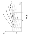
- FIG. 2 is a schematic view showing an approximate relationship between the PLR Er, transmit power q, communication distance x, environment attenuation index n, and ambient noise of the active RFID tag;
- FIG. 3 is a schematic view showing the position of critical transition area when the active RFID tag works at different transmit powers
- FIG. 4 is a schematic view showing critical transition areas corresponding to each given signal transmit power and receiver flexibility of the active RFID tag
- FIG. 5 is a unit structure view showing a system for positioning using the active FRID tag according to an embodiment of the present invention
- FIG. 6 is a schematic view showing a system for positioning using reference signals according to an embodiment of the present invention.
- FIG. 7 is a schematic view showing that the active RFID tag switches to a second channel to transmit multiple groups of ranging signals at different transmit powers upon receiving wakeup signals on a first channel;
- FIG. 8 is a schematic view showing multi-dimensional positioning using multiple active RFID readers
- FIG. 9 is a schematic view showing positioning using a directional antenna in a polar coordinate
- FIG. 10 is time sequence diagram of signal control in a positioning system using the active RFID tag and RFID reader without a coordinator, where the active RFID tag works in interception-prioritized mode, and changes to transmitting-first-and-then-intercepting mode upon receiving call signals to determine whether the active RFID reader enters the interception mode but still works on the same channel;
- FIG. 11 is a schematic view showing that the active RFID tag, after entering the transmitting-first-and-then-intercepting mode as shown in FIG. 10 , transmits ranging signal packets according to a command received from the active RFID reader;
- FIG. 12 is a schematic view showing an application example of the active RFID tag in the positioning system according to an embodiment of the present invention, where the coordinator is connected to a control process (network and control computer in the figure); the coordinator may be also independent of the control processor.
- n is the environment attenuation index indicating how much the transmission environment affects the signal attenuation, n being 2 in an ideal environment, and n ranging from 2 to 4 in normal cases. Referring to FIG. 1 , it is obviously a monotone function. Under the same signal strength, the greater the environment attenuation index, the shorter the distance between the receiver and the signal source. From FIG. 1 , n 3 >n 2 >n 1 .
- the receiver when the signal strength at the signal receiver is greater than the receiver flexibility ps of the signal receiver, the receiver can receive the signal. In such a case, the distance between the signal receiver and the signal source is the communication distance therebetween.
- the signal receiver due to factors such as interior and exterior noise interferences from the signal receiver, the signal receiver produces bit errors during signal receiving.
- f(SNR) is an inverse function of g(Er). These two functions are only related to the signal receiver feature and communication mode, do not vary with the environment, and can be tested in a lab or site in advance.
- the SNR and Er are in one-to-one relationship. If the noise strength N is given, the SNR is in one-to-one relationship with the signal strength p. Therefore, Er is in one-to-one relationship with the signal strength p.
- the PER Er used in the present invention is defined to the ratio of the difference (number of lost packets) between the number of signal packets received by the signal receiver and the total number of signal packets to the total number of signal packets sent from the signal source, that is, the PLR.
- the PER is calculated by calculating the PLR during packet receiving.
- the environment attenuation index n may be assumed to a constant.
- the given source for example, active RFID tag
- signal receiver for example, active RFID reader
- n is the environment attenuation index only related to the transmission environment but not related to the ambient noise.
- b(N) can be tested on-site.
- the ambient noise is not a constant value, which varies with the time and change of the noise source.
- the noise strength is inversely proportional to the square of the noise transmission distance
- a remote noise source cause a small impact on the variation of ambient noise within a limited positioning range. If there are no other noise sources, it may be considered that the ambient noise only varies with the time and not the location within this limited positioning range. Therefore, the noise varying with the time may affect the value of b(N).
- G(Er) is a factor affecting the working feature of the signal transmitter having a signal source and the communication mode, which is not related to other factors. The detailed reason is described in the following section.
- n the value of n is given.
- different PERs are represented by different straight parallel lines, forming a zonal area with a slope of n.
- the environment attenuation index n determines only the slope of the straight line in the logarithmic coordinator.
- the change of the PER and average noise strength is equivalent to one-unit translation of the original straight line along the vertical direction q and horizontal direction (x).
- n, g(Er), and b(N) can be determined by actual test on-site, by using experimental formulas, or by combining experience and actually tested data. It should be noted that different ambient noises N correspond to different b(N) values. With the actually n, b(N), and g(Rr) in the actual test environment, the distance x between the signal source and signal receiver can be calculated by using the actually tested Er and the queried transmit power q of the ranging signal corresponding to Er so as to implement positioning of the active RFID tag.
- b(N) is related to the ambient noise, and therefore, in the practice of positioning, the ambient noise value actually tested on-site needs for calculation. While being used to test the signal PER, the signal receiver is to test the ambient noise N to calculate the new value of b(N); or a correction is made to b(N) by using the reference signal source.
- n The value of n can be determined as follows:
- n the value of n can be calculated.
- a method similar to the preceding one can be used to calculate the value of n in the anechoic chamber environment, and the value of A is calculated by changing the transmit power q and measuring different signal strength p at the signal source x.
- the value of b(N) can be obtained by measuring the ambient noise value in each positioning.
- the simplest method for determining the function g(Er) is testing in the lab.
- the function can be determined by measuring the PERs corresponding to different SNR p/N.
- other methods can be used to determine this function.
- the value of b(N) is affected by the ambient noise.
- b(N) varies with the ambient noise. Therefore, during the test of the position of the target, while being used to test the signal PER, the signal receiver is to test the ambient noise N to test the value of N; or a correction is made to N by using the reference signal source.
- the value of b(N) is corrected during actual test by using the reference signal source to eliminate or reduce the impact caused by the ambient noise.
- the test using a single signal receiver usually produces a great deviation.
- multiple repeated tests can fully reflect the preceding transmission regularity, which is also the theory basis of the technical solution provided in the present invention.
- the target can be positioned by measuring the relative distance between the signal source (target) and signal receivers (for example, signal receivers 1 , 2 , and 3 ) whose positions are known. Measuring the relative distance can overcome factors affecting the positioning, such as the ambient noise N and signal transmitter feature parameter A. For example, the position of the target can be determined by measuring the relative distances between the target and the three signal receivers on the plane respectively.
- x 1 and x 2 are respectively the distances between the signal source and the two signal transceiver units 1 and 2 whose positions are known
- q 1 and q 2 are respectively the transmit powers of the ranging signals sent from the signal source
- p 1 and p 2 are respectively the signal strengths when the ranging signals are transmitted and when they are received at the signal receiver
- n is the environment attenuation index.
- the function relationships between Er and G(Er) obtained in the lab and on-site are the same; under the condition that the ambient noise is given, the PER is only related to the signal strength. If the signal strength is greater than the noise strength, signals can be received; otherwise, no signal can be received. The signal strength is in a monotonic relationship with the PER.
- the target When multiple signal receivers are used and the target is positioned by collecting signals sent by the target at the same time period, the relative distances between the target and the multiple signal receivers and the known distances between the multiple signal receivers are used to calculate the position of the moving target. This prevents the impact caused by the ambient noise or other system errors.
- x 1 /x 2 [( q 1 g ( Er 2 ))/( q 2 g ( Er 1 ))] 1/n
- the relative distance between multiple RFID tags and the same receiving unit rather than the accurate distance between the RFID tag and the RFID reader is needed.
- the charging system needs to distinguish the vehicle before and the following vehicle when multiple vehicles are coming to the toll gate.
- the signal receivers 1 and 2 need to combine into one signal receiver, and meanwhile all RFID tags use the same signal transmit power when this formula is used to calculate the relative distance. In this manner, the near vehicle and the following vehicle can be distinguished according to the PLR.
- the ratio of distances between the target to be positioned and the three signal receivers can be directly calculated according to the powers of the three signal receivers and the corresponding PERs, without using the reference signal source; and the position of the target can be determined according to the positions of the three signal receivers.
- a signal receiving transition area or unstable area is formed near a position where the signal strength exceeds the receiver flexibility of the signal receiver.
- the signal receiver PER decreases with the increase of the distance, a sharp decrease from 100% to 0% (see FIGS. 3 and 4 ).
- This area is also called a critical transition area as regards the transmit power at the signal source and the signal receiver.
- the transmit power corresponding middle value of the PER range 1%-99% is called the critical transmit power.
- the signal source can transmit ranging signals at different transmit powers.
- the same position x may correspond to different groups of values of q and Er, as shown in FIG. 3 . It is recommended that the group of values where the PER is most close to the middle value within the range of 1%-99%, or the group of values corresponding to the critical transmit power are used to reduce the error.
- the signal source for example, the active RFID tag (or RFID tag)
- the active RFID tag uses different transmit powers to transmit ranging signals to firstly search out the critical transmit power corresponding to the RFID tag.
- the PER in signal receiving by the signal receiver for example, active RFID reader
- the signal receiver for example, active RFID reader
- the PER sharply decreases to be close to 0% and becomes insensitive to the above-mentioned distance change.
- the PER sharply increases to be infinite and receives no signals, and in such a case, therefore, the PER is insensitive to the above-mentioned distance change.
- the active RFID tag uses the critical transmit power to transmit signals
- the signal receiver is covered within its critical signal receiving area. Within this range, when the PER becomes sensitive to the change of the distance between the signal receiver and the active RFID tag (see FIGS. 3 and 4 ). Therefore, the test result is more accurate. If the PER 40% is defined to the central position in the critical signal receiving area, the transmit power where the PER is closest to 40% can be taken as the critical transmit power to be determined when signals are transmitted at different transmit powers and the PER corresponding to each transmit power is obtained. The distance between the active RFID tag and the active RFID reader is calculated using the pre-determined relationship between the transmit power, corresponding PER, and distance, and the PER tested when the signals are transmitted at the transmit power.
- the signal transmission mode can be changed for the active RFID tag according to actual conditions to reduce the working time of the active RFID tag to reduce energy consumption.
- the active RFID tag can be set to transmit signals at multiple transmit powers.
- the number of signal packets transmitted at each transmit power needs to be, for example, 3-5.
- the active RFID tag transmit multiple signal packets at the critical transmit power to calculate a more accurate PER. If the distance range between the active RFID tag and the active RFID reader is pre-determined, a more accurate PER corresponding to the critical transmit power can be directed obtained, after multiple signal packets are transmitted continuously at two to three transmit powers close to the corresponding critical transmit power, to calculate the distance between the active RFID tag and the active RFID reader.
- a system for positioning using an active RFID tag includes:
- an active RFID tag 501 configured to continuously and repeatedly transmit a predetermined number of ranging signal packets
- a transceiver unit 502 configured to receive the ranging signals from the active RFID tag
- a counter unit 503 connected to the transceiver unit 502 and configured to count the ranging signal packets received from the transceiver unit 502 within a predetermined time period;
- a PLR calculating unit 504 configured to calculate the PLR of the ranging signals according to the number of received ranging signal packets received by the ranging signal collecting unit and the predicated number of data packets transmitted by an active RFID tag within a predetermined time period;
- a position determining unit 505 configured to determine, based on a predetermined policy (concluded formula), the position of the active RFID tag according to the PLR and transmit power of the ranging signals;
- control and storage unit 506 configured to control the communication between the transceiver unit 502 and the active RFID tag 501 , and receive the position information from the position determining unit 505 and store it;
- a ranging signal collecting unit comprised of the transceiver unit 502 and the control and storage unit 506 , configured to collect ranging signals from a ranging signal transmitting unit, where the ranging signal transmitting unit may be an active RFID tag.
- the above-mentioned units may be integrated to form an active RFID reader and control processor.
- the transceiver unit forms an active RFID reader
- the counter unit, PLR calculating unit, position determining unit, and control and storage unit may be integrated to form a control processor; or the transceiver unit and counter unit may be integrated to form an active RFID reader, the PLR calculating unit, position determining unit, and control and storage unit may be integrated to form a control processor; or the transceiver unit, counter unit, and PLR calculating unit may be integrated to form an active RFID reader, and the position determining unit and control and storage unit may be integrated to form a control processor; or the transceiver unit, counter unit, and PLR calculating unit, and position determining unit may be integrated to form an active RFID reader, and the control and storage unit forms a control processor.
- the position determining unit needs to be integrated into the control processor.
- the system for positioning using the active RFID tag includes an active RFID tag, an active RFID reader, and a control processor.
- system may also includes:
- a reference signal source (as shown in FIG. 6 ), configured to correct b(N) in the preset policy to reduce the impact from the ambient noise changes to positioning of the active RFID tag and ranging signal transmitting unit, according to the preset x and q values at the reference signal source when positioning the active RFID tag and ranging signal transmitting unit;
- a directional antenna (as shown in FIG. 9 ), configured to receive or transmit signals, and determine the direction of the active RFID tag according to the direction of the antenna;
- a coordinator or call machine (as shown in FIG. 12 ), configured to transmit wakeup signals continuously on a wakeup channel (channel F 1 ); upon receiving the wakeup signals, the active RFID tag receives the wakeup signals after waking up from a periodical dormant state in the interception time period, and switches to channel F 2 to transmit ranging signals to the active RFID reader; or the active RFID tag changes its working mode or transmits signals in a set transmission node according to command for the working mode of the active RFID tag and the ranging signal transmission mode contained in the wakeup signals.
- the active RFID tag is further configured to transmit call signals to the transceiver unit, and transmits the ranging signals according to the command signals received through the (transceiver unit in) the coordinator from the control processor.
- the active RFID tag is generally (but not limited to be) formed by a micro-wave single-chip transceiver and a single-chip microcomputer.
- the micro-wave single-chip transceiver and the single-chip microcomputer may be integrated on one chip.
- the active RFID tag's transmit power can be adjusted by software or other methods. It is generally powered by the battery and carried by the target to be positioned. Considering energy saving, the active RFID tag can be made to work alternatively in the working and standby states. The active RFID tag stays in the standby state with low power consumption most of the time. It enters the working state for a short time period only after receiving wakeup signals or call signals when it is required to work. After finishing a task, it quickly returns to the standby state.
- the active RFID tag In the standby state, the active RFID tag periodically stays in the dormant state or interception state. When it is in the dormant state, the crystal oscillator and frequency synthesizer are all disabled, consuming less power. When it is in the interception state, the crystal oscillator and frequency synthesizer are enabled.
- standby state The instant low power consumption state when the active RFID tag periodically enter the dormant state and wakes up and intercepts signals on the first channel is called standby state, which is a basic state that the active RFID tag can maintain for a long time.
- the active RFID tag When receiving the wakeup signals from the coordinator, the active RFID tag switches to the working channel and communicates with the RFID reader, or performs other operations according to commands, which is called the working state.
- the RFID tag can maintain for a short time period.
- the working mode of the active RFID is more flexible, and it can be always in the working state for receiving or transmitting signals.
- the communication distance between the active RFID tag and active RFID reader ranges between 0.1 m and 2000 m.
- the active RFID reader is connected to the control processor, and is a signal transceiver that can communicate with the active RFID tag and reference signal source.
- the active RFID reader has a relatively fixed position and is generally powered by an external power supply. When necessary, it also provides the RSSI function.
- the control processor is generally a computer, and is connected to the active RFID reader. It can control the active RFID reader, store, and process various data required for positioning.
- the reference signal source is an active RFID tag or another RFID reader.
- the distance between the reference signal source and the given RFID reader is pre-determined.
- the active RFID tag or active RFID reader needs to have the same or similar working feature in signal transmission as or to the active RFID tag carried by the target.
- the reference signal source is mainly used to correct the actual positioning test, that is, correct b(N), when the change of the ambient noise produces impacts on the test results.
- other parameters reflecting ambient noise changes such as the RSSI value (N) tested when the active RFID reader is receiving signals, can also be used to correct b(N).
- the coordinator is a common signal transmitter, which is generally powered by an external power supply and collaborates with the active RFID reader to work. It uses an interception instance after the active RFID periodically wakes up from the dormant state to transmit command signals to the active RFID tag to adjust its working state. In this manner, the active RFID is energy saving and carries out information exchange with the RFID reader for positioning according to actual requirements. Accordingly, the coordinator usually works on different channels from the active RFID reader. It may be arranged with the active RFID reader at either the same position or different positions (see FIGS. 7 and 9 ).
- the following section uses the active RFID reader formed by the transceiver unit, counter unit, and PLR calculating unit, and the control processor formed by the position determining unit and control and storage unit as examples to describe the embodiments.
- the workers can be positioned if the active RFID tags carried by the workers or one active RFID tag fixedly arranged in the mine tunnel is detected, or the distance between two active RFID readers are measured.
- the active RFID reader may be arranged at the entrance of each positioning section.
- only one active RFID reader is arranged.
- the active RFID reader and coordinator are arranged at the entrance of the mine, a reference signal source is arranged at a position, for example 300 meters, away from the active RFID reader, and the works enter the mine tunnel carrying active RFID tags.
- the position of the reference signal source is for illustration only.
- the reference signal source, active RFID tag, and active RFID reader are arranged on the same straight line or on a known curve; whereas in a two-dimensional space, that is, planar space, the reference signal source may be not arranged on the straight line where the active RFID tag and active RFID reader are arranged (except the case where the directional antenna is used).
- the reference signal source transmit ranging signals at a position that is x meters, for example 300 meters away from the active RFID reader.
- the active RFID reader receives the ranging signals, counts the signals received within a pre-determined time period, and determines the pre-stored PLR Er according to the number of ranging signals transmitted by the reference signal source within the pre-determined time period. For example, within 1 ms, the reference signals source transmits 100 signal packets, but actually 55 signal packets are received.
- the reference signal source is arranged at a position where the PLR is close to the middle value within the range of 1%-99%.
- g(Er) corresponding to the PLR Er is determined and G(Er) is thus determined according to the pre-determined relationship between the PLR Er and g(Er).
- the active RFID reader pre-stores the transmit power q of the ranging signals from the reference signal, and n is also pre-determined. Accordingly, x, q, G(Er), and n in the preceding formula are known so that b(N), that is, b(Nnew), in the positioning of the target can be determined to increase test accuracy which is affected by b(N) varying with the ambient noise.
- the ranging signals are transmitted at different transmit powers using the reference signal source to determine the PLR Er.
- the PLR is a preferred PLR corresponding to a transmit power among different transmit powers.
- Step 2 A coordinator (not shown in FIG. 6 ) continuously and repeatedly transmits wakeup signals to the active RFID tag on the wakeup channel (channel F 1 ).
- the coordinator may be connected to or separate from the control processor. It may transmit wakeup signals under control of the control processor or transmit wakeup signals according to a pre-determined process.
- Step 3 The active RFID tag in the standby state receives the wakeup signals on the wakeup channel, switches to the working channel (channel F 2 ), and transmits ranging signals to the active RFID reader in a pre-determined ranging signal transmission mode within the interception time period or transmits ranging signals in the specified ranging signal transmission mode according to the information contained in the wakeup signals that is used for controlling the mode for the active RFID tag to transmit ranging signals (as shown in FIG. 7 ).
- signals can be transmitted to the active RFID reader at different transmit powers Specifically, a pre-set number of ranging signals are continuously transmitted at each transmit power by turn.
- the power grade can be multiple, which is determined by the feature of the active RFID tag.
- a command can be used to set the number of power grades to be used.
- the number of ranging signals transmitted at each transmit power can be set using a command. For example, as shown in FIG. 7 , a ranging signal is transmitted repeatedly and continuously to the active RFID reader at transmit powers 1 , 2 , and 3 cyclically; or 100 ranging signals are transmitted continuously to the active RFID reader at transmit powers 1 , 2 , and 3 respectively and repeatedly.
- the information, contained in the wakeup signals, for controlling the mode for the active RFID tag to transmit ranging signals may be either commands or action command indexes. Therefore, the active RFID reader can transmit the ranging signals according to the commands, or finds and execute, according to the pre-set mapping between the index and action, the active command corresponding to the action command index to transmit the ranging signals.
- Step 4 Upon receiving the ranging signals, the active RFID reader respectively calculate the PLR of the ranging signals transmitted at each transmit powers, and transmit the calculated PLR to the control processor.
- Step 5 The control processor select a preferred PLR according to the received PLRs corresponding to different transmit powers, and determine the corresponding transmit powers for transmitting the ranging signals and G(Er).
- a preferred PLR refers to a PLR close to the middle value with the range of 1%-99%.
- a PLR of 40% is preferred.
- the active RFID reader provides the PER information useful for positioning to the control processor by receiving the PLRs when the active RFID tag and reference signal source transmit a pre-determined number of ranging signals at different transmit powers.
- the control processor pre-stores the information about the mode for the active RFID tag to transmit ranging signals and the power of the ranging signals transmitted at each transmit power. Therefore, the corresponding power of the ranging signal can be queried according to a preferred PLR.
- the query method is: the transmit power of the ranging signal with the smallest PLR is corresponding to that of the ranging signal with the largest PLR, and the transmit power of the ranging signal with the second smallest PLR is corresponding to that of the ranging signal with the second largest PLR.
- the transmit power corresponding to the preferred PLR can be determined.
- two active RFID readers are arranged in the straight mine tunnel, with positioned known, which are represented by active RFID reader 1 and active RFID reader 2 .
- three active RFID readers are arranged in a planar space, with positions known, represented by active RFID reader 1 , active RFID reader 2 , and active RFID reader 3 .
- the method described in the first embodiment can be used to calculate a preferred PLR Er 1 for the active RFID reader 1 (the transceiver unit 1 corresponding to the active RFID reader 1 ) to determine q 1 and g(Er 1 ); calculate a preferred PLR Er 2 for the active RFID reader 2 (the transceiver unit 2 corresponding to the active RFID reader 2 ) to determine q 2 and g(Er 2 ); calculate a preferred PLR Er 3 for the active RFID reader 3 (the transceiver unit 3 corresponding to the active RFID reader 3 ) to determine q 3 and g(Er 3 ); and calculate the distances x 1 , x 2 , and x 3 between the active RFID tag and the active RFID reader 1 (transceiver unit 1 ), active RFID reader 2 (transceiver unit 1 ),
- the control processor (a control processing unit in) transmits the determinate position information about the active RFID tag through the active RFID reader (transceiver unit in) to the active RFID tag or transmits the PLR or the number of received ranging signals within the predetermined time period to the active RFID tag.
- the active RFID tag determines its own position according to the saved in advance formula (or called predetermined policy).
- the system for positioning the active RFID tag includes: an active RFID tag, control processor, coordinator, reference signal source, directional antenna 1 , and directional antenna 2 .
- Step 2 The coordinator continuously sends wakeup signals to the active RFID tag in different direction on a wakeup channel (channel F 1 ) by rotating the directional antenna 1 .
- Step 3 When the directional antenna rotates to the direction of the active RFID tag, the active RFID tag in the standby state receives wakeup signals from the coordinator on the wakeup channel with the interception time period. Upon receiving the wakeup signals, the active RFID tag switches to the working channel (channel F 2 ) immediately to transmit the ranging signals in the pre-determined ranging signal transmission mode, or transmits the ranging signals in the pre-determined ranging signal transmission mode according to the information contained in the wakeup signals that is used for controlling the mode for the active RFID tag to transmit ranging signals.
- the working channel channel F 2
- Step 4 Upon receiving these ranging signals by the directional antenna 2 , the active RFID reader determines the direction of the active RFID tag, and calculates the PLR of the ranging signals transmitted at each transmit power and transmits to the control processor.
- the directional antenna 1 connected to the coordinator and the directional 2 connected to the active RFID reader always point to the same direction; the directional antenna 1 only transmits the wakeup signals, while the directional antenna 2 can not only receive signals, for example, receive ranging signals, but also transmit signals, but signal receiving and transmitting need to be carried out at different moments.
- the active RFID reader receives the ranging signals through the directional antenna 2 only when the active RFID tag is in the direction of the directional antenna. Therefore, the directional antennas 1 and 2 determine the direction of the active RFID tag according to the direction of the ranging signals.
- Step 5 According to the received PLRs corresponding to different transmit powers, the control processor selects a preferred PLR, determines the transmit power of the ranging signal according to the preferred PLR, and determines g(Er) corresponding to the preferred PLR q according to the pre-determined relationship between E(r) and g(Er). Refer to the method for determining the preferred PLR and g(Er) value described in the first embodiment.
- the system for positioning the active RFID tag in one dimensional space includes: an active RFID tag, control processor, coordinator, and two active RFID readers, active RFID reader 1 and active RFID reader 2 , arranged in straight tunnel.
- Step 1 The coordinator continuously transmits wakeup signals to the active RFID tag on the wakeup channel (channel F 1 ).
- Step 2 The active RFID tag in the standby state receives the wakeup signals on the wakeup channel in the interception time period, and switches to the working channel (channel F 2 ) to transmit the ranging signals to the active RFID tag in the pre-determined ranging signal transmission mode, or transmits the ranging signals according to the information contained in the wakeup signals that is used for controlling the mode for the active RFID tag to transmit ranging signals.
- Step 3 Upon receiving these ranging signals, the active RFID reader calculates the PLR of the ranging signals transmitted at each transmit power and transmits the PLR to the control processor.
- Step 4 According to the received PLRs corresponding to different transmit powers, the control processor selects a preferred PLR, determines the transmit power of the ranging signal according to the preferred PLR, and determines g(Er) corresponding to the preferred PLR q according to the pre-determined relationship between E(r) and g(Er). Refer to the method for determining the preferred PLR and g(Er) value described in the first embodiment.
- a preferred PLR Er 1 transmit power q 1 of the ranging signals corresponding to Er 1 , and g(Er 1 ) can be determined.
- a preferred PLR Er 2 transmit power q 2 of the ranging signals corresponding to Er 2 , and g(Er 2 ) can be determined.
- the control processor can determine the ratio of the distance between the active RFID tag and the active RFID reader 1 to the distance between the active RFID tag and the active RFID reader 2 .
- the active RFID tag in a two-dimensional space (planar space)
- three active RFID readers are arranged on the planar space, with positions known, which are represented by active RFID reader 1 , active RFID reader 2 , and active RFID reader 3 .
- the method described in the fifth embodiment can be used to calculate a preferred PLR Er 1 for the active RFID reader 1 (the transceiver unit 1 corresponding to the active RFID reader 1 ) to determine q 1 and g(Er 1 ); calculate a preferred PLR Er 2 for the active RFID reader 2 (the transceiver unit 2 corresponding to the active RFID reader 2 ) to determine q 2 and g(Er 2 ); and calculate a preferred PLR Er 2 for the active RFID reader 3 (the transceiver unit 2 corresponding to the active RFID reader 3 ) to determine q 3 and g(Er 3 ).
- x 1 /x 2 [q 1 g(Er 2 )/q 2 g(Er 1 )] 1/n
- x 2 /x 3 [q 2 g(Er 3 )/q 3 g(Er 2 )] 1/n
- x 1 , x 2 , and x 3 are the distances respectively between the active RFID tag and the active RFID readers (or transceiver units corresponding to the active RFID readers) 1 , 2 , and 3 whose positions are pre-determined. Accordingly, the position of the active RFID tag is determined.
- the method for positioning the active RFID tag described in the fourth embodiment and the method for positioning the active RFID tag by calculating the ratio of the distance between the active RFID tag and active RFID reader 1 to the distance between the active RFID tag and active RFID reader 2 can be referred to.
- the positioning system includes: a coordinator, active RFID tag, active RFID reader 1 , active RFID reader 2 , directional antenna 1 , and directional antenna 2 .
- the positions of the active RFID readers 1 and 2 are known.
- the coordinator is connected to the directional antenna 1 and transmits wakeup signals through the directional antenna 1 ;
- the active RFID reader 2 (or active RFID reader 1 ) is connected to the directional antenna 2 , and receive signals, for example, ranging signals, through the directional antenna 2 .
- the directional antennas 1 and 2 always point to the same direction.
- reader 2 When receiving the ranging signals from the active RFID tag, reader 2 determines the direction of the active RFID tag according to the direction the directional antenna 2 points to; and determines the ratio of the distance between the active RFID tag and active RFID reader 1 to the distance between the active RFID tag and active RFID reader 2 according to the ranging signals received respectively from the active RFID readers 1 and 2 .
- x 1 /x 2 [q 1 g ( Er 2 )/ q 2 g ( Er 1 )] 1/n ,
- control processor determines the position of the active RFID tag according to the direction and value x 1 /x 2 .
- the positioning system consists of an active RFID tag and active RFID reader, as shown in FIGS. 10 and 11 .
- Step 1 The active RFID reader continuously transmits call signals to the active RFID tag on a wakeup channel (channel F 1 ) for a specific period and then switches to the signal receiving state.
- the duration for continuously transmitting call signals should be at least longer than the dormancy-interception time period the active RFID tag to ensure that the active RFID tag has at least one chance to intercept the call signals when the active RFID reader transmits call signals.
- Step 2 The active RFID tag in the standby state receives the call signals on the wakeup channel in the interception time period, and switches to the working mode according to the command information included in the call signals, for example, directly sending to the ranging signals after waiting for a specific period (the period at least longer than the duration for transmitting call signals of the active RFID reader to ensure that the active RFID reader entering the signal receiving state) or switching to the working modes for periodically transmitting request signals and receiving returned command signals.
- the active RFID tag periodically transmits request signals to the active RFID reader on the wakeup channel (channel F 1 ).
- the command signals can include the ID of the active RFID tag. If the active RFID tag transmits request signals but active RFID reader does not switch to the signal receiving state, the active RFID reader cannot receive the request signals from the active RFID reader.
- Step 3 Upon receiving the command signals, the active RFID reader transmits returned signals to the active RFID tag on the wakeup channel (channel F 1 ).
- the active RFID reader Upon switching to the signal receiving state, the active RFID reader can receive the request signals sent by the active RFID tag periodically.
- Step 4 The active RFID tag receives returned command signals upon transmitting request signals, and transmits ranging signals in a specified mode according to the receiving returned command signals, or switches to the standby state.
- Step 5 The active RFID reader receives the ranging signals and determines the position of the active RFID tag.
- the active reader here can be one or multiple so that the position of the active RFID tag in one-dimensional and two-dimensional spaces is implemented, referring to the first, second, third, fifth and sixth embodiments, which are not detailed here.
- the position of the active RFID tag in the three-dimensional space can be implemented in combination with the directional antenna, referring to the fourth and seventh embodiments.
- the conventional RFID technology used for vehicle management is categorized into passive RFID and active RFID.
- ETC electronic toll collection system
- the problem is to prevent signal misreading by identifying that the vehicle radio frequency identity received by each RFID reader is the vehicle identity signal the system should process rather than signals transmitted by vehicles on the neighboring driveways or the following vehicles far away from the toll gate.
- the RFID reader arranged in the passage in addition to restricting the signal transmission direction using the directional antenna, restricts coverage of the signals to prevent signal misreading. Therefore, the signal coverage of the RFID reader is narrowed down. Vehicle speed needs to be lowered when passing through the toll gate to ensure that the RFID reader has sufficient time to receive and process signals. Low vehicle speed definitely reduces the usage efficiency of the highway.
- the technical solution provided in the present invention can easily solve the technical problem.
- the accurate distance between the active RFID tag and each active RFID reader or the impact caused by the environment interference on the precision is not concerned.
- the interference signals transmitted by vehicles on the neighboring driveways or following vehicles far from the toll gate only need to be shielded.
- it is only necessary to determine that RFID reader that the RFID tag actually passes through is the nearest one among all RFID readers that the active RFID tag passes through and that receive the signal transmitted by the RFID tag. Accordingly, a reference signal source, a pre-determined transmit power, and relationship between the PER and distance are not required.
- an RFID tag when getting close to the RFID reader at the toll gate, continuously transmits multiple signal packets at different transmit power close to the critical transmit power.
- the interference signals transmitted by the vehicles on the neighboring driveways or following vehicles far from the toll gate can be shielded according to the principle that the minimum transmit power and PER corresponds to the minimum distance.
- physical means such as metal plats can be used to increase the different in PER during signal transmission when the RFID readers receive signals transmitted by different RFID tags.
Landscapes
- Engineering & Computer Science (AREA)
- Physics & Mathematics (AREA)
- General Physics & Mathematics (AREA)
- Radar, Positioning & Navigation (AREA)
- Remote Sensing (AREA)
- Computer Networks & Wireless Communication (AREA)
- Signal Processing (AREA)
- Radar Systems Or Details Thereof (AREA)
- Position Fixing By Use Of Radio Waves (AREA)
- Mobile Radio Communication Systems (AREA)
Abstract
Description
x 1 /x 2 =[q 1 g(Er 2)/q 2 g(Er 1)]1/n
x 1 /x 2 /x 3=[(q 1 g(Er 2)g(Er 3))/(q 2 g(Er 1)g(Er 3))/(q 3 g(Er 1)g(Er 2))]1/n
p=Aqx −n,
p/N=Aqx −n /N=SNR=g(Er)
ln(p/N)=ln q −n×ln x−ln(N/A)
ln q=n×ln x+ln(p/N)+ln(N/A)
ln q=n×ln x+ln g(Er)+ln(N/A)
ln q=n×ln x+G(Er)+b(N),
- where, G(Er)=ln g(Er), b(N)=ln(N/A), and therefore
ln x=[ln q−G(Er)−b(N)]/n
ln(x 1 /x 2)=[ln q 1−ln(p 1 /N)]/n−[ln q 2−ln(p 2 /N)]/n
ln(x 1 /x 2)=[(ln q 1−ln q 2)+ln(p 2 /N)−ln(p 1 /N)]/n
ln(x 1 /x 2)={ln(q 1 /q 2)+ln [(p 2 /N)/(p 1 /N)]}/n
ln(x 1 /x 2)=[ln(q 1 /q 2)+ln(p 2 /p 1)]/n
x 1 /x 2=[(q 1 p 2)/(q 2 p 1)]1/n
SNR=p/N=g(Er)
x 1 /x 2=[(q 1 g(Er 2))/(q 2 g(Er 1))]1/n
x 1 /x 2=[(q 1 g(Er 2))/(q 2 g(Er 1))]1/n
x 2 /x 3=[(q 2 g(Er 3))/(q 3 g(Er 2))]1/n
x 1 /x 2 /x 3=[(q 1 g(Er 2)g(Er 3))/(q 2 g(Er 1)g(Er 3))/(q 3 g(Er 1)g(Er 2))]1/n
x 1 /x 2 /x 3=[(q 1 g(Er 2)g(Er 3))/(q 2 g(Er 1)g(Er 3))/(q 3 g(Er 1)g(Er 2))]1/n
x 1 /x 2 =[q 1 g(Er 2)/q 2 g(Er 1)]1/n,
Claims (16)
ln x=[ln q−G(Er)−b(N)]/n, where
x 1 /x 2 /x 3=[(q 1 g(Er 2)g(Er 3))/(q 2 g(Er 1)g(Er 3))/(q 3 g(Er 1)g(Er 2))]1/n,
ln x=[ln q−G(Er)−b(N)]/n, where
x 1 /x 2 /x 3=[(q 1 g(Er 2)g(Er 3))/(q 2 g(Er 1)g(Er 3))/(q 3 g(Er 1)g(Er 2))]1/n,
Applications Claiming Priority (4)
| Application Number | Priority Date | Filing Date | Title |
|---|---|---|---|
| CN200910058045 | 2009-01-06 | ||
| CN200910058045.3 | 2009-01-06 | ||
| CN200910058045.3A CN101770009B (en) | 2009-01-06 | 2009-01-06 | New accurate and practical radio-frequency positioning technology |
| PCT/CN2010/070041 WO2010078844A1 (en) | 2009-01-06 | 2010-01-06 | System and method for positioning using signal transmission power and signal reception bit-error-rate |
Related Parent Applications (1)
| Application Number | Title | Priority Date | Filing Date |
|---|---|---|---|
| PCT/CN2010/070041 Continuation WO2010078844A1 (en) | 2009-01-06 | 2010-01-06 | System and method for positioning using signal transmission power and signal reception bit-error-rate |
Publications (2)
| Publication Number | Publication Date |
|---|---|
| US20110260923A1 US20110260923A1 (en) | 2011-10-27 |
| US8242958B2 true US8242958B2 (en) | 2012-08-14 |
Family
ID=42316265
Family Applications (1)
| Application Number | Title | Priority Date | Filing Date |
|---|---|---|---|
| US13/176,425 Expired - Fee Related US8242958B2 (en) | 2009-01-06 | 2011-07-05 | System and method for positioning using signal transmit power and signal receive packet error ratio |
Country Status (3)
| Country | Link |
|---|---|
| US (1) | US8242958B2 (en) |
| CN (1) | CN101770009B (en) |
| WO (1) | WO2010078844A1 (en) |
Cited By (2)
| Publication number | Priority date | Publication date | Assignee | Title |
|---|---|---|---|---|
| US8994512B2 (en) | 2010-11-01 | 2015-03-31 | Omron Corporation | RFID system |
| US20220196815A1 (en) * | 2019-09-18 | 2022-06-23 | Guangdong Oppo Mobile Telecommunications Corp., Ltd. | Method for processing frame loss of ultrasonic wave, mobile terminal and storage medium |
Families Citing this family (38)
| Publication number | Priority date | Publication date | Assignee | Title |
|---|---|---|---|---|
| CN102063742A (en) * | 2010-07-12 | 2011-05-18 | 上海搜林信息技术有限公司 | Method, system and device for eliminating interference from adjacent channels in electronic automatic fare collection system |
| CN101995580A (en) * | 2010-08-13 | 2011-03-30 | 赵永频 | Interactive positioning capable of setting long-distance and short-distance mobility of gathering site |
| CN102568043B (en) * | 2010-12-23 | 2014-01-08 | 博通集成电路(上海)有限公司 | Method and vehicle-mounted unit for electronic tolling system |
| CN102393896B (en) * | 2011-07-11 | 2014-08-27 | 成都西谷曙光数字技术有限公司 | Simple and accurate radio frequency positioning system and method |
| CN102435976B (en) * | 2011-09-13 | 2013-11-13 | 上海无线电设备研究所 | Maritime emergency position indicating system |
| CN102423515B (en) * | 2011-09-13 | 2013-12-04 | 上海无线电设备研究所 | Portable personal beacon |
| GB201117723D0 (en) | 2011-10-13 | 2011-11-23 | Sensewhere Ltd | Method of estimating the position of a user device using radio beacons and radio beacons adapted to facilitate the methods of the invention |
| DE102011054926A1 (en) * | 2011-10-28 | 2013-05-02 | Caterpillar Global Mining Europe Gmbh | Method and system for increasing the operational safety of mobile machines in surface mining or underground mines for the extraction of minerals using RFID technology |
| US8690412B2 (en) * | 2012-03-15 | 2014-04-08 | Apple Inc. | Backlight structures and backlight assemblies for electronic device displays |
| WO2013181720A1 (en) | 2012-06-07 | 2013-12-12 | Mindspark Technologies Pty Ltd | Methods, systems and devices for monitoring movement of rock in a mine |
| US9183419B2 (en) * | 2013-01-02 | 2015-11-10 | The Boeing Company | Passive RFID assisted active RFID tag |
| US10401488B2 (en) | 2013-06-26 | 2019-09-03 | University Of Virginia Patent Foundation | Real-time RFID localization using uniform, high-performance tags and related method thereof |
| US9596650B2 (en) * | 2013-09-11 | 2017-03-14 | Microsemi Corporation | Radio wake-up system with multi-mode operation |
| CN103559535B (en) * | 2013-11-11 | 2016-04-27 | 中国矿业大学 | A kind of mining positioning label and power-saving working method |
| CN103605126B (en) * | 2013-11-21 | 2016-06-29 | 天津中兴智联科技有限公司 | Radio frequency identification speed measurement method and device |
| CN104375135B (en) * | 2014-11-05 | 2017-02-15 | 西藏舟航物联科技有限公司 | Radio frequency positioning method, device and system |
| CN104333869A (en) * | 2014-11-28 | 2015-02-04 | 重庆大学 | Portable intelligent cell phone signal sensing equipment and portable intelligent cell phone signal sensing method |
| US9801019B2 (en) | 2015-03-16 | 2017-10-24 | Qualcomm Incorporated | Adaptive triggering of RTT ranging for enhanced position accuracy |
| CN104794506B (en) * | 2015-04-14 | 2017-11-14 | 天津七一二通信广播股份有限公司 | It is a kind of using laser ranging can adjust automatically transmission power internet-of-things terminal |
| JP6491948B2 (en) * | 2015-05-13 | 2019-03-27 | 株式会社東芝 | Electric vehicle position detection system |
| CN105491650B (en) * | 2015-12-29 | 2019-11-19 | 深圳市海云天科技股份有限公司 | The power adaptive method of adjustment and system of frequency read/write |
| CN106997039B (en) * | 2016-01-22 | 2021-09-21 | 中国矿业大学(北京) | Underground TOA positioning method for coal mine by constraining underground reconstruction one-dimensional space through virtual plane |
| CN106774304B (en) * | 2016-11-21 | 2019-11-26 | 河源职业技术学院 | A kind of AGV trolley path planning method and system based on directional aerial |
| KR20180099041A (en) * | 2017-02-28 | 2018-09-05 | 삼성전자주식회사 | Method for proximity sensing of object and electronic device using the same |
| CN107220572B (en) * | 2017-06-27 | 2024-01-26 | 天津市滨海新区军民融合创新研究院 | Method, device and system for testing sensitivity and packet error rate of radio frequency reader |
| CN111386713B (en) * | 2017-11-01 | 2022-06-10 | 王裕隆 | Portable marine sign indicating system |
| CN108594172B (en) * | 2018-04-08 | 2022-06-14 | 深圳市盛路物联通讯技术有限公司 | Method, storage medium, system and central processing unit for radio frequency signal distance measurement |
| CN110868752B (en) * | 2018-08-28 | 2022-01-11 | 阿里巴巴集团控股有限公司 | Terminal positioning method and device |
| CN109544744A (en) * | 2018-11-20 | 2019-03-29 | 北京千丁互联科技有限公司 | Intelligent door lock communication system and method |
| CN109858302B (en) * | 2019-01-31 | 2020-05-15 | 清华大学 | Label reflection coefficient optimization method and device of environment reflection communication system |
| WO2020256630A1 (en) * | 2019-06-18 | 2020-12-24 | Cadi Scientific Pte Ltd | Devices, systems, and methods for location tracking or proximity detection |
| CN112203212A (en) * | 2019-06-19 | 2021-01-08 | 厦门雅迅网络股份有限公司 | Bluetooth positioning method based on packet loss rate and computer readable storage medium |
| CN111263304B (en) * | 2020-01-17 | 2021-06-04 | 广东中电富嘉工贸有限公司 | LoRa communication parameter setting method in fixed area and electronic shackle thereof |
| CN112307789B (en) * | 2020-10-29 | 2024-02-23 | 上海坤锐电子科技有限公司 | Electronic tag working method, electronic tag and electronic tag system |
| CN112285755A (en) * | 2020-11-04 | 2021-01-29 | 桂林慧谷人工智能产业技术研究院 | Finding-missing seamless positioning system and positioning method |
| CN113030856A (en) * | 2021-03-24 | 2021-06-25 | 江西昌河汽车有限责任公司 | RFID vehicle positioning system based on RSSI algorithm and positioning method thereof |
| CN116299398B (en) * | 2023-05-23 | 2023-08-29 | 石家庄银河微波技术股份有限公司 | Target ranging method and device applied to aircraft and electronic equipment |
| CN118393432B (en) * | 2024-06-27 | 2024-09-17 | 徐州稻源龙芯电子科技有限公司 | Passive RFID positioning method for quantifying transmitting power |
Citations (10)
| Publication number | Priority date | Publication date | Assignee | Title |
|---|---|---|---|---|
| US20030143956A1 (en) | 2001-09-30 | 2003-07-31 | Ronald Taylor | RF channel linking method and system |
| CN1924609A (en) | 2005-08-30 | 2007-03-07 | 富士通株式会社 | RFID tag device, RFID reader/writer device, and distance measuring system |
| WO2007130746A2 (en) * | 2006-03-28 | 2007-11-15 | The Board Of Governors For Higher Education, State Of Rhode Island And Providence Plantations | Systems and methods for distance estimation between electronic devices |
| CN101114019A (en) | 2007-04-20 | 2008-01-30 | 清华大学 | Radio frequency electronic label position location system based on trigonometric interpolation |
| CN101131432A (en) | 2007-09-18 | 2008-02-27 | 澳门科技大学 | Positioning method for wireless radio frequency recognition system and device thereof |
| US20080165058A1 (en) * | 2007-01-04 | 2008-07-10 | International Business Machines Corporation | Spatially locating radio tags for on demand systems |
| JP2008232907A (en) | 2007-03-22 | 2008-10-02 | Kyushu Ten:Kk | Ranging system and its ranging method |
| CN101335956A (en) * | 2008-08-05 | 2008-12-31 | 深圳市中兴集成电路设计有限责任公司 | System and method for communication distance determination using BER statistical data |
| US20090051547A1 (en) * | 2007-08-20 | 2009-02-26 | Radio Systems Corporation | Antenna Proximity Determining System Utilizing Bit Error Rate |
| US20100201573A1 (en) * | 2009-02-06 | 2010-08-12 | Michael George Lamming | Ranging transceiver based activity monitoring system |
Family Cites Families (4)
| Publication number | Priority date | Publication date | Assignee | Title |
|---|---|---|---|---|
| US7280810B2 (en) * | 2005-08-03 | 2007-10-09 | Kamilo Feher | Multimode communication system |
| CN1818713A (en) * | 2006-03-16 | 2006-08-16 | 秦忠 | Ultrasonic positioning method of active long-range radio-frequency electronic label |
| CN201003413Y (en) * | 2007-01-23 | 2008-01-09 | 包头奥普德电子科技有限公司 | Down-hole safe alarming and personnel management device for coal mine |
| CN101236611B (en) * | 2007-02-02 | 2012-07-18 | 成都西谷曙光数字技术有限公司 | Intelligent electronic label system |
-
2009
- 2009-01-06 CN CN200910058045.3A patent/CN101770009B/en not_active Expired - Fee Related
-
2010
- 2010-01-06 WO PCT/CN2010/070041 patent/WO2010078844A1/en active Application Filing
-
2011
- 2011-07-05 US US13/176,425 patent/US8242958B2/en not_active Expired - Fee Related
Patent Citations (10)
| Publication number | Priority date | Publication date | Assignee | Title |
|---|---|---|---|---|
| US20030143956A1 (en) | 2001-09-30 | 2003-07-31 | Ronald Taylor | RF channel linking method and system |
| CN1924609A (en) | 2005-08-30 | 2007-03-07 | 富士通株式会社 | RFID tag device, RFID reader/writer device, and distance measuring system |
| WO2007130746A2 (en) * | 2006-03-28 | 2007-11-15 | The Board Of Governors For Higher Education, State Of Rhode Island And Providence Plantations | Systems and methods for distance estimation between electronic devices |
| US20080165058A1 (en) * | 2007-01-04 | 2008-07-10 | International Business Machines Corporation | Spatially locating radio tags for on demand systems |
| JP2008232907A (en) | 2007-03-22 | 2008-10-02 | Kyushu Ten:Kk | Ranging system and its ranging method |
| CN101114019A (en) | 2007-04-20 | 2008-01-30 | 清华大学 | Radio frequency electronic label position location system based on trigonometric interpolation |
| US20090051547A1 (en) * | 2007-08-20 | 2009-02-26 | Radio Systems Corporation | Antenna Proximity Determining System Utilizing Bit Error Rate |
| CN101131432A (en) | 2007-09-18 | 2008-02-27 | 澳门科技大学 | Positioning method for wireless radio frequency recognition system and device thereof |
| CN101335956A (en) * | 2008-08-05 | 2008-12-31 | 深圳市中兴集成电路设计有限责任公司 | System and method for communication distance determination using BER statistical data |
| US20100201573A1 (en) * | 2009-02-06 | 2010-08-12 | Michael George Lamming | Ranging transceiver based activity monitoring system |
Non-Patent Citations (6)
| Title |
|---|
| English translation of CN 101335956 A. * |
| English translation of Xi'an. * |
| Intermittent, The Penguin English Dictionary, 2007. Retrieved from http://www.credoreference.com/entry/penguineng/intermittent. * |
| Xi'an Saycool, Brief Introduction of the Innovative Technology about the 2.4G Over-long Rang and Low-Energy-Consumption Active RFID of Saycool, Sep. 15, 2009. |
| Yan, Yan et al, Design and Application of Active Radio Frequency Identification System, Computer Engineering, Jun. 2008, vol. 34 No. 11, pp. 234-236. |
| Yang, Tianrong, Active RFID, China Electrical Market (Radio Frequency Identification Technologies and Applications), Feb. 2008, No. 1, pp. 36-39. |
Cited By (2)
| Publication number | Priority date | Publication date | Assignee | Title |
|---|---|---|---|---|
| US8994512B2 (en) | 2010-11-01 | 2015-03-31 | Omron Corporation | RFID system |
| US20220196815A1 (en) * | 2019-09-18 | 2022-06-23 | Guangdong Oppo Mobile Telecommunications Corp., Ltd. | Method for processing frame loss of ultrasonic wave, mobile terminal and storage medium |
Also Published As
| Publication number | Publication date |
|---|---|
| WO2010078844A1 (en) | 2010-07-15 |
| CN101770009B (en) | 2014-05-21 |
| US20110260923A1 (en) | 2011-10-27 |
| CN101770009A (en) | 2010-07-07 |
Similar Documents
| Publication | Publication Date | Title |
|---|---|---|
| US8242958B2 (en) | System and method for positioning using signal transmit power and signal receive packet error ratio | |
| CN207835830U (en) | Positioning system | |
| US9063212B2 (en) | Indoor navigation with low energy location beacons | |
| CN101191832B (en) | Wireless sensor network node position finding process based on range measurement | |
| CN102014489B (en) | Environment adaptive RSSI local positioning system and method | |
| US11861963B2 (en) | Smart lock, smart monitoring system and smart monitoring method | |
| CN113271540B (en) | Bluetooth signal positioning method, multi-signal fusion positioning method and system | |
| CN102638763B (en) | Underground electromagnetic-wave ultrasound united positioning system and method | |
| CN101175292A (en) | Wireless micro-power network positioning system and locating method thereof | |
| US20120001728A1 (en) | Method and system for determining location information | |
| US20180143287A1 (en) | System, device, node, and method for tracking a device | |
| CN106793087A (en) | A kind of array antenna indoor positioning algorithms based on AOA and PDOA | |
| CN104066172A (en) | Method for positioning AP in wireless local area network | |
| CN102036372A (en) | Signal strength-based positioning method for non-uniform loss factors | |
| CN105527605A (en) | Multimode hybrid indoor positioning method | |
| CN106888504A (en) | Indoor location fingerprint positioning method based on FM Yu DTMB signals | |
| CN101795466A (en) | Wireless micropower network positioning system and positioning method thereof | |
| CN206057553U (en) | It is a kind of to be based on bidirectional ranging indoor accurate positioning system | |
| CN108307343A (en) | A kind of high precision wireless indoor orientation method and system | |
| CN102821463B (en) | Signal-strength-based indoor wireless local area network mobile user positioning method | |
| CN105872977A (en) | Improved LANDMARAC locating algorithm for wireless sensor network | |
| CN105791438A (en) | WIFI positioning system based on mobile terminal networking | |
| CN104570034A (en) | Composite precise positioning system and positioning method thereof | |
| CN101795486B (en) | Wireless micropower network positioning system and positioning method thereof | |
| CN101795467A (en) | Wireless micropower network positioning system and positioning method thereof |
Legal Events
| Date | Code | Title | Description |
|---|---|---|---|
| AS | Assignment |
Owner name: WESTVALLEY DIGITAL TECHNOLOGIES, INC., CHINA Free format text: ASSIGNMENT OF ASSIGNORS INTEREST;ASSIGNORS:LIAO, JASON Y.;SUN, CHANGZHENG;REEL/FRAME:026543/0771 Effective date: 20110627 |
|
| STCF | Information on status: patent grant |
Free format text: PATENTED CASE |
|
| FEPP | Fee payment procedure |
Free format text: PAYER NUMBER DE-ASSIGNED (ORIGINAL EVENT CODE: RMPN); ENTITY STATUS OF PATENT OWNER: SMALL ENTITY Free format text: PAYOR NUMBER ASSIGNED (ORIGINAL EVENT CODE: ASPN); ENTITY STATUS OF PATENT OWNER: SMALL ENTITY |
|
| FPAY | Fee payment |
Year of fee payment: 4 |
|
| FEPP | Fee payment procedure |
Free format text: MAINTENANCE FEE REMINDER MAILED (ORIGINAL EVENT CODE: REM.); ENTITY STATUS OF PATENT OWNER: SMALL ENTITY |
|
| LAPS | Lapse for failure to pay maintenance fees |
Free format text: PATENT EXPIRED FOR FAILURE TO PAY MAINTENANCE FEES (ORIGINAL EVENT CODE: EXP.); ENTITY STATUS OF PATENT OWNER: SMALL ENTITY |
|
| STCH | Information on status: patent discontinuation |
Free format text: PATENT EXPIRED DUE TO NONPAYMENT OF MAINTENANCE FEES UNDER 37 CFR 1.362 |