US8239191B2 - Speech encoding apparatus and speech encoding method - Google Patents
Speech encoding apparatus and speech encoding method Download PDFInfo
- Publication number
- US8239191B2 US8239191B2 US12/440,661 US44066107A US8239191B2 US 8239191 B2 US8239191 B2 US 8239191B2 US 44066107 A US44066107 A US 44066107A US 8239191 B2 US8239191 B2 US 8239191B2
- Authority
- US
- United States
- Prior art keywords
- signal
- speech
- noise
- section
- tilt compensation
- Prior art date
- Legal status (The legal status is an assumption and is not a legal conclusion. Google has not performed a legal analysis and makes no representation as to the accuracy of the status listed.)
- Active, expires
Links
- 238000000034 method Methods 0.000 title claims description 31
- 239000000284 extract Substances 0.000 claims abstract description 7
- 238000013139 quantization Methods 0.000 claims description 67
- 230000005284 excitation Effects 0.000 claims description 48
- 238000001914 filtration Methods 0.000 claims description 44
- 238000012546 transfer Methods 0.000 claims description 39
- 230000003595 spectral effect Effects 0.000 claims description 32
- 238000007493 shaping process Methods 0.000 claims description 24
- 238000004458 analytical method Methods 0.000 claims description 20
- 230000003044 adaptive effect Effects 0.000 claims description 11
- 230000007423 decrease Effects 0.000 claims description 10
- 230000003247 decreasing effect Effects 0.000 claims description 2
- 238000001228 spectrum Methods 0.000 abstract description 33
- 238000004364 calculation method Methods 0.000 abstract description 11
- 238000012937 correction Methods 0.000 abstract description 5
- 230000005236 sound signal Effects 0.000 abstract 2
- 230000015572 biosynthetic process Effects 0.000 description 73
- 238000003786 synthesis reaction Methods 0.000 description 73
- 230000006870 function Effects 0.000 description 46
- 238000009499 grossing Methods 0.000 description 37
- 238000012545 processing Methods 0.000 description 34
- 238000012986 modification Methods 0.000 description 33
- 230000004048 modification Effects 0.000 description 33
- 238000010586 diagram Methods 0.000 description 30
- 238000001514 detection method Methods 0.000 description 21
- 230000004044 response Effects 0.000 description 21
- 230000000694 effects Effects 0.000 description 13
- 230000001629 suppression Effects 0.000 description 6
- 230000007774 longterm Effects 0.000 description 5
- 238000005516 engineering process Methods 0.000 description 4
- 238000013459 approach Methods 0.000 description 3
- 230000015556 catabolic process Effects 0.000 description 3
- 238000006731 degradation reaction Methods 0.000 description 3
- 230000010354 integration Effects 0.000 description 3
- 238000005311 autocorrelation function Methods 0.000 description 2
- 238000004891 communication Methods 0.000 description 2
- 238000010295 mobile communication Methods 0.000 description 2
- 239000006227 byproduct Substances 0.000 description 1
- 230000010365 information processing Effects 0.000 description 1
- 238000004519 manufacturing process Methods 0.000 description 1
- 230000000873 masking effect Effects 0.000 description 1
- 239000004065 semiconductor Substances 0.000 description 1
- 238000005303 weighing Methods 0.000 description 1
Images
Classifications
-
- G—PHYSICS
- G10—MUSICAL INSTRUMENTS; ACOUSTICS
- G10L—SPEECH ANALYSIS TECHNIQUES OR SPEECH SYNTHESIS; SPEECH RECOGNITION; SPEECH OR VOICE PROCESSING TECHNIQUES; SPEECH OR AUDIO CODING OR DECODING
- G10L19/00—Speech or audio signals analysis-synthesis techniques for redundancy reduction, e.g. in vocoders; Coding or decoding of speech or audio signals, using source filter models or psychoacoustic analysis
- G10L19/04—Speech or audio signals analysis-synthesis techniques for redundancy reduction, e.g. in vocoders; Coding or decoding of speech or audio signals, using source filter models or psychoacoustic analysis using predictive techniques
- G10L19/26—Pre-filtering or post-filtering
- G10L19/265—Pre-filtering, e.g. high frequency emphasis prior to encoding
-
- G—PHYSICS
- G10—MUSICAL INSTRUMENTS; ACOUSTICS
- G10L—SPEECH ANALYSIS TECHNIQUES OR SPEECH SYNTHESIS; SPEECH RECOGNITION; SPEECH OR VOICE PROCESSING TECHNIQUES; SPEECH OR AUDIO CODING OR DECODING
- G10L19/00—Speech or audio signals analysis-synthesis techniques for redundancy reduction, e.g. in vocoders; Coding or decoding of speech or audio signals, using source filter models or psychoacoustic analysis
- G10L19/04—Speech or audio signals analysis-synthesis techniques for redundancy reduction, e.g. in vocoders; Coding or decoding of speech or audio signals, using source filter models or psychoacoustic analysis using predictive techniques
- G10L19/08—Determination or coding of the excitation function; Determination or coding of the long-term prediction parameters
Definitions
- the present invention relates to a speech encoding apparatus and speech encoding method of a CELP (Code-Excited Linear Prediction) scheme. More particularly, the present invention relates to a speech encoding apparatus and speech encoding method for correcting quantization noise to human perceptual characteristics and improving subjective quality of decoded speech signals.
- CELP Code-Excited Linear Prediction
- quantization noise is made hard to be heard by shaping quantization noise in accordance with human perceptual characteristics.
- quantization noise is shaped using a perceptual weighting filter in which the transfer function is expressed by following equation 1.
- Equation 1 is equivalent to following equation 2.
- a i represents the LPC (Linear Prediction Coefficient) element acquired in the process of CELP encoding
- M represents the order of the LPC.
- ⁇ 1 and ⁇ 2 are formant weighting coefficients for adjusting the weights of formants in quantization noise.
- the values of formant weighting coefficients ⁇ 1 and ⁇ 2 are empirically determined by listening.
- optimal values of formant weighting coefficients ⁇ 1 and ⁇ 2 vary according to frequency characteristics such as the spectral slope of a speech signal itself, or according to whether or not formant structures are present in a speech signal, and whether or not harmonic structures are present in a speech signal.
- a perceptual weighting filter between a background noise period and a speech period
- the characteristics of a perceptual weighting filter are switched depending on whether each period in an input signal is a speech period or a background noise period (i.e., inactive speech period).
- a speech period is a period in which speech signals are predominant
- a background noise period is a period in which non-speech signals are predominant. According to the techniques disclosed in Patent Document 2, by distinguishing between a background noise period and a speech period and switching the characteristics of a perceptual weighting filter, it is possible to perform perceptual weighting filtering suitable for each period of a speech signal.
- the speech encoding apparatus of the present invention employs a configuration having: a linear prediction analyzing section that performs a linear prediction analysis with respect to a speech signal to generate linear prediction coefficients; a quantizing section that quantizes the linear prediction coefficients; a perceptual weighting section that performs perceptual weighting filtering with respect to an input speech signal to generate a perceptual weighted speech signal using a transfer function including a tilt compensation coefficient for adjusting a spectral slope of a quantization noise; a tilt compensation coefficient control section that controls the tilt compensation coefficient using a signal to noise ratio of the speech signal in a first frequency band; and an excitation search section that performs an excitation search of an adaptive codebook and fixed codebook to generate an excitation signal using the perceptual weighted speech signal.
- the speech encoding method of the present invention employs a configuration having the steps of: performing a linear prediction analysis with respect to a speech signal and generating linear prediction coefficients; quantizing the linear prediction coefficients; performing perceptual weighting filtering with respect to an input speech signal and generating a perceptual weighted speech signal using a transfer function including a tilt compensation coefficient for adjusting a spectral slope of a quantization noise; controlling the tilt compensation coefficient using a signal to noise ratio in a first frequency band of the speech signal; and performing an excitation search of an adaptive codebook and fixed codebook to generate an excitation signal using the perceptual weighted speech signal.
- the present invention it is possible to adaptively adjust the spectral slope of quantization noise while suppressing influence on the level of formant weighting, and further perform perceptual weighting filtering suitable for a noise-speech superposition period in which background noise signals and speech signals are superposed on one another.
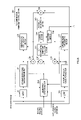
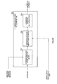
- FIG. 1 is a block diagram showing the main components of a speech encoding apparatus according to Embodiment 1 of the present invention
- FIG. 2 is a block diagram showing the configuration inside a tilt compensation coefficient control section according to Embodiment 1 of the present invention
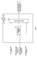
- FIG. 3 is a block diagram showing the configuration inside a noise period detecting section according to Embodiment 1 of the present invention.
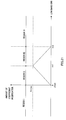
- FIG. 4 illustrates an effect acquired by shaping quantization noise of a speech signal in a speech period in which speech is predominant over background noise, using a speech encoding apparatus according to Embodiment 1 of the present invention
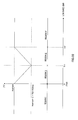
- FIG. 5 illustrates an effect acquired by shaping quantization noise of a speech signal in a noise-speech superposition period in which background noise and speech are superposed on one another, using a speech encoding apparatus according to Embodiment 1 of the present invention
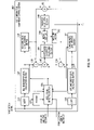
- FIG. 6 is a block diagram showing the main components of a speech encoding apparatus according to Embodiment 2 of the present invention.
- FIG. 7 is a block diagram showing the main components of a speech encoding apparatus according to Embodiment 3 of the present invention.
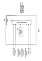
- FIG. 8 is a block diagram showing the configuration inside a tilt compensation coefficient control section according to Embodiment 3 of the present invention.
- FIG. 9 is a block diagram showing the configuration inside a noise period detecting section according to Embodiment 3 of the present invention.
- FIG. 10 is a block diagram showing the configuration inside a tilt compensation coefficient control section according to Embodiment 4 of the present invention.
- FIG. 11 is a block diagram showing the configuration inside a noise period detecting section according to Embodiment 4 of the present invention.
- FIG. 12 is a block diagram showing the main components of a speech encoding apparatus according to Embodiment 5 of the present invention.
- FIG. 13 is a block diagram showing the configuration inside a tilt compensation coefficient control section according to Embodiment 5 of the present invention.
- FIG. 14 illustrates a calculation of tilt compensation coefficients in a tilt compensation coefficient calculating section according to Embodiment 5 of the present invention
- FIG. 15 illustrates an effect acquired by shaping quantization noise using a speech encoding apparatus according to Embodiment 5 of the present invention
- FIG. 16 is a block diagram showing the main components of a speech encoding apparatus according to Embodiment 6 of the present invention.
- FIG. 17 is a block diagram showing the configuration inside a weight coefficient control section according to Embodiment 6 of the present invention.
- FIG. 18 illustrates a calculation of a weight adjustment coefficient in a weight coefficient calculating section according to Embodiment 6 of the present invention
- FIG. 19 is a block diagram showing the configuration inside a tilt compensation coefficient control section according to Embodiment 7 of the present invention.
- FIG. 20 is a block diagram showing the configuration inside a tilt compensation coefficient calculating section according to Embodiment 7 of the present invention.
- FIG. 21 illustrates a relationship between low band SNRs and a coefficient correction amount according to Embodiment 7 of the present invention.
- FIG. 22 illustrates a relationship between a tilt compensation coefficient and low band SNRs according to Embodiment 7 of the present invention.
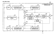
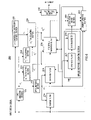
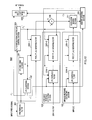
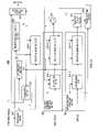
- FIG. 1 is a block diagram showing the main components of speech encoding apparatus 100 according to Embodiment 1 of the present invention.
- speech encoding apparatus 100 is provided with LPC analyzing section 101 , LPC quantizing section 102 , tilt compensation coefficient control section 103 , LPC synthesis filters 104 - 1 and 104 - 2 , perceptual weighting filters 105 - 1 , 105 - 2 and 105 - 3 , adder 106 , excitation search section 107 , memory updating section 108 and multiplexing section 109 .
- LPC synthesis filter 104 - 1 and perceptual weighting filter 105 - 2 form zero input response generating section 150
- LPC synthesis filter 104 - 2 and perceptual weighting filter 105 - 3 form impulse response generating section 160 .
- LPC analyzing section 101 performs a linear prediction analysis with respect to an input speech signal and outputs the linear prediction coefficients to LPC quantizing section 102 and perceptual weighting filters 105 - 1 to 105 - 3 .
- LPC quantizing section 102 quantizes linear prediction coefficients a i received as input from LPC analyzing section 101 , outputs the quantized linear prediction coefficients a ⁇ i to LPC synthesis filters 104 - 1 to 104 - 2 and memory updating section 108 , and outputs the LPC encoding parameter C L to multiplexing section 109 .
- Tilt compensation coefficient control section 103 calculates tilt compensation coefficient ⁇ 3 to adjust the spectral slope of quantization noise using the input speech signal, and outputs the calculated ⁇ 3 to perceptual weighting filters 105 - 1 to 105 - 3 . Tilt compensation coefficient control section 103 will be described later in detail.
- LPC synthesis filter 104 - 1 performs synthesis filtering of a zero vector to be received as input, using the transfer function shown in following equation 3 including quantized linear prediction coefficients a ⁇ i received as input from LPC quantizing section 102 .
- LPC synthesis filter 104 - 1 uses as a filter state an LPC synthesis signal fed back from memory updating section 108 which will be described later, and outputs a zero input response signal acquired by synthesis filtering, to perceptual weighting filter 105 - 2 .
- LPC synthesis filter 104 - 2 performs synthesis filtering of an impulse vector received as input using the same transfer function as the transfer function in LPC synthesis filter 104 - 1 , that is, using the transfer function shown in equation 3, and outputs the impulse response signal to perceptual weighting filter 105 - 3 .
- the filter state in LPC synthesis filter 104 - 2 is the zero state.
- Perceptual weighting filter 105 - 1 performs perceptual weighting filtering with respect to the input speech signal using the transfer function shown in equation 4 including the linear prediction coefficients a i received as input from LPC analyzing section 101 and tilt compensation coefficient ⁇ 3 received as input from tilt compensation coefficient control section 103 .
- ⁇ 1 and ⁇ 2 are formant weighting coefficients.
- Perceptual weighting filter 105 - 1 outputs a perceptual weighted speech signal acquired by perceptual weighting filtering, to adder 106 .
- the state in the perceptual weighting filter is updated in the process of the perceptual weighting filtering processing. That is, the filter state is updated using the input signal for the perceptual weighting filter and the perceptual weighted speech signal as the output signal from the perceptual weighting filter.
- Perceptual weighting filter 105 - 2 performs perceptual weighting filtering with respect to the zero input response signal received as input from LPC synthesis filter 104 - 1 , using the same transfer function as the transfer function in perceptual weighting filter 105 - 1 , that is, using the transfer function shown in equation 4, and outputs the perceptual weighted zero input response signal to adder 106 .
- Perceptual weighting filter 105 - 2 uses the perceptual weighting filter state fed back from memory updating section 108 , as the filter state.
- Perceptual weighting filter 105 - 3 performs filtering with respect to the impulse response signal received as input from LPC synthesis filter 104 - 2 , using the same transfer function as the transfer function in perceptual weighting filter 105 - 1 and perceptual weighting filter 105 - 2 , that is, using the transfer function shown in equation 4, and outputs the perceptual weighted impulse response signal to excitation search section 107 .
- the state in perceptual weighting filter 105 - 3 is the zero state.
- Adder 106 subtracts the perceptual weighted zero input response signal received as input from perceptual weighting filter 105 - 2 , from the perceptual weighted speech signal received as input from perceptual weighting filter 105 - 1 , and outputs the signal as a target signal, to excitation search section 107 .
- Excitation search section 107 is provided with a fixed codebook, adaptive codebook, gain quantizer and such, and performs an excitation search using the target signal received as input from adder 106 and the perceptual weighted impulse response signal received as input from perceptual weighting filter 105 - 3 , outputs the excitation signal to memory updating section 108 and outputs excitation encoding parameter C E to multiplexing section 109 .
- Memory updating section 108 incorporates the same LPC synthesis filter with LPC synthesis filter 104 - 1 and the same perceptual weighting filter with perceptual weighting filter 105 - 2 .
- Memory updating section 108 drives the internal LPC synthesis filter using the excitation signal received as input from excitation search section 107 , and feeds back the LPC synthesis signal as a filter state to LPC synthesis filter 104 - 1 .
- memory updating section 108 drives the internal perceptual weighting filter using the LPC synthesis signal generated in the internal LPC synthesis filter, and feeds back the filter state in the perceptual weighting synthesis filter to perceptual weighting filter 105 - 2 .
- the perceptual weighting filter incorporated in memory updating section 108 is formed with a cascade connection of three filters of a tilt compensation filter expressed by the first term of above equation 4, weighting LPC inverse filter expressed by the numerator of the second term of above equation 4, and weighting LPC synthesis filter expressed by the denominator of the second term of above equation 4, and further feeds back the states in these three filters to perceptual weighting filter 105 - 2 . That is, the output signal of the tilt compensation filter for the perceptual weighting filter, which is incorporated in memory updating section 108 , is used as the state in the tilt compensation filter forming perceptual weighting filter 105 - 2 ,
- an input signal of the weighting LPC inverse filter for the perceptual weighting filter, which is incorporated in memory updating section 108 is used as the filter state in the weighting LPC inverse filter of perceptual weighting filter 105 - 2
- an output signal of the weighting LPC synthesis filter for the perceptual weighting filter, which is incorporated in memory updating section 108 is used as the filter state in the weighting LPC synthesis filter of perceptual weighting filter 105 - 2 .
- Multiplexing section 109 multiplexes encoding parameter C L of quantized LPC (a i ) received as input from LPC quantizing section 102 and excitation encoding parameter C E received as input from excitation search section 107 , and transmits the resulting bit stream to the decoding side.
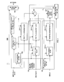
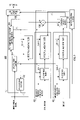
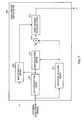
- FIG. 2 is a block diagram showing the configuration inside tilt compensation coefficient control section 103 .
- tilt compensation coefficient control section 103 is provided with HPF 131 , high band energy level calculating section 132 , LPF 133 , low band energy level calculating section 134 , noise period detecting section 135 , high band noise level updating section 136 , low band noise level updating section 137 , adder 138 , adder 139 , adder 140 , tilt compensation coefficient calculating section 141 , adder 142 , threshold calculating section 143 , limiting section 144 and smoothing section 145 .
- HPF 131 is a high pass filter, and extracts high band components of an input speech signal in the frequency domain and outputs the high band components of speech signal to high band energy level calculating section 132 .
- High band energy level calculating section 132 calculates the energy level of high band components of speech signal received as input from HPF 131 on a per frame basis, according to following equation 5, and outputs the energy level of high band components of speech signal to high band noise level updating section 136 and adder 138 .
- E H 10 log 10 (
- E H is a decibel representation of
- LPF 133 is a low pass filter, and extracts low band components of the input speech signal in the frequency domain and outputs the low band components of speech signal to low band energy level calculating section 134 .
- Low band energy level calculating section 134 calculates the energy level of low band components of the speech signal received as input from LPF 133 on a per frame basis, according to following equation 6, and outputs the energy level of low band components of speech signal to low band noise level updating section 137 and adder 139 .
- E L 10 log 10 (
- E L is a decibel representation of
- Noise period detecting section 135 detects whether the speech signal received as input on a per frame basis belongs to a period in which only background noise is present, and, if a frame received as input belongs to a period in which only background noise is present, outputs background noise period detection information to high band noise level updating section 136 and low band noise level updating section 137 .
- a period in which only background noise is present refers to a period in which speech signals to constitute the core of conversation are not present and in which only surrounding noise is present. Further, noise period detecting section 135 will be described later in detail.
- High band noise level updating section 136 holds an average energy level of high band components of background noise, and, when the background noise period detection information is received as input from noise period detecting section 135 , updates the average energy level of high band components of background noise, using the energy level of the high band components of speech signal, received as input from high band energy level calculating section 132 .
- E H represents the energy level of the high band components of speech signal, received as input from high band energy level calculating section 132 . If background noise period detection information is received as input from noise period detecting section 135 to high band noise level updating section 136 , assume that the input speech signal is comprised of only background noise periods, and that the energy level of high band components of background noise, received as input from high band energy level calculating section 132 to high band noise level updating section 136 , that is, E H in this equation 7 is the energy level of high band components of background noise.
- E NH represents the average energy level of high band components of background noise, held in high band noise level updating section 136
- ⁇ is the long term smoothing coefficient of 0 ⁇ 1.
- High band noise level updating section 136 outputs the average energy level of high band components of background noise to adder 138 and adder 142 .
- Low band noise level updating section 137 holds the average energy level of low band components of background noise, and, when the background noise period detection information is received as input from noise period detecting section 135 , updates the average level of low band components of background noise, using the energy level of low band components of speech signal, received as input from low band energy level calculating section 134 .
- E L represents the energy level of the low band components of speech signal received, as input from low band energy level calculating section 134 . If background noise period detection information is received as input from noise period detecting section 135 to low band noise level updating section 137 , assume that the input speech signal is comprised of only background noise periods, and that the energy level of low band components of speech signal received as input from low band energy level calculating section 134 to low band noise level updating section 137 , that is, E L in this equation 8, is the energy level of low band components of background noise.
- E NL represents the average energy level of low band components of background noise held in low band noise level updating section 137
- ⁇ is the long term smoothing coefficient of 0 ⁇ 1.
- Low band noise level updating section 137 outputs the average energy level of the low band components of background noise to adder 139 and adder 142 .
- Adder 138 subtracts the average energy level of high band components of background noise received as input from high band noise level updating section 136 , from the energy level of the high band components of speech signal received as input from high band energy level calculating section 132 , and outputs the subtraction result to adder 140 .
- the subtraction result acquired in adder 138 shows the difference between two energy levels showing energy using logarithm, that is, the subtraction result shows the difference between the energy level of the high band components of speech signal and the average energy level of high band components of background noise. Consequently, the subtraction result shows a ratio of these two energies, that is, the ratio between energy of high band components of speech signal and average energy of high band components of background noise.
- the subtraction result acquired in adder 138 is the high band SNR (Signal-to-Noise Ratio) of a speech signal.
- Adder 139 subtracts the average energy level of low band components of background noise received as input from low band noise level updating section 137 , from the energy level of low band components of speech signal received as input from low band energy level calculating section 134 , and outputs the subtraction result to adder 140 .
- the subtraction result acquired in adder 139 shows the difference between two energy levels represented by logarithm, that is, the subtraction result shows the difference between the energy level of the low band components of speech signal and the average energy level of low band components of background noise. Consequently, the subtraction result shows a ratio of these two energies, that is, the ratio between energy of low band components of speech signal and long term average energy of low band components of background noise signal.
- the subtraction result acquired in adder 13 is the low band SNR of a speech signal.
- Adder 140 performs subtraction processing of the high band SNR received as input from adder 138 and the low band SNR received as input from adder 139 , and outputs the difference between the high band SNR and the low band SNR, to tilt compensation coefficient calculating section 141 .
- Tilt compensation coefficient calculating section 141 calculates tilt compensation coefficient before smoothing, ⁇ 3 ′, according to, for example, following equation 9, using the difference received as input from adder 140 between the high band SNR and the low band SNR, and outputs the calculated tilt compensation coefficient ⁇ 3 ′ to limiting section 144 .
- ⁇ 3 ′ ⁇ (low band SNR ⁇ high band SNR)+ C (Equation 9)
- ⁇ 3 ′ represents the tilt compensation coefficient before smoothing
- ⁇ represents a predetermined coefficient
- C represents the bias component.
- tilt compensation coefficient calculating section 141 calculates the tilt compensation coefficient before smoothing, ⁇ 3 ′, using a function where ⁇ 3 ′ increases in proportion to the difference between the low band SNR and the high band SNR.
- perceptual weighting filters 105 - 1 to 105 - 3 perform shaping of quantization noise using the tilt compensation coefficient before smoothing, ⁇ 3 ′, when the low band SNR is higher than the high band SNR, weighting with respect to error of the low band components of an input speech signal becomes significant and weighting with respect to error of the high band components becomes insignificant relatively, and therefore the high band components of the quantization noise is shaped higher.
- the high band SNR is higher than the low band SNR
- weighting with respect to error of the high band components of an input speech signal becomes significant and weighting with respect to error of the low band components becomes insignificant relatively, and therefore the low band components of the quantization noise is shaped higher.
- Adder 142 adds the average energy level of high band components of background noise received as input from high band noise level updating section 136 and the average energy level of low band components of background noise received as input from low band noise level updating section 137 , and outputs the average energy level of background noise acquired as the addition result to threshold calculating section 143 .
- Threshold calculating section 143 calculates an upper limit value and lower limit value of tilt compensation coefficient before smoothing, ⁇ 3 ′, using the average energy level of background noise received as input from adder 142 , and outputs the calculated upper limit value and lower limit value to limiting section 144 .
- ⁇ average energy level of background noise
- the upper limit value of the tilt compensation coefficient before smoothing is fixed to a constant that is determined empirically.
- a proper calculation formula and value vary according to the performance of the HPF and LPF, bandwidth of the input speech signal, and so on.
- the upper limit value may be set around 0.6 upon encoding a narrowband signal and around 0.9 upon encoding a wideband signal.
- the lowermost limit value may be set around ⁇ 0.5 upon encoding a narrowband signal and around 0.4 upon encoding a wideband signal.
- ⁇ 3 ′ Necessity for setting the lower limit value of tilt compensation coefficient before smoothing, ⁇ 3 ′, using the average energy level of background noise, will be explained.
- weighting with respect to low band components becomes insignificant when ⁇ 3 ′ is smaller, and low band quantization noise is shaped high.
- the energy of a speech signal is generally concentrated in the low band, and, consequently, in almost all of the cases, it is proper to shape low band quantization noise low. Therefore, shaping low band quantization noise high needs to be performed carefully.
- the high band SNR and low band SNR calculated in adder 138 and adder 139 are likely to be influenced by the accuracy of noise period detection in noise period detecting section 135 and local noise, and, consequently, the reliability of tilt compensation coefficient before smoothing, ⁇ 3 ′, calculated in tilt compensation coefficient calculating section 141 , may decrease.
- the low band quantization noise may be shaped too high by mistake, which makes the low band quantization noise too high, and, consequently, a method of preventing this is required.
- the low band components of quantization noise are not shaped too high when the average energy level of background noise is low.
- Limiting section 144 adjusts the tilt compensation coefficient before smoothing, ⁇ 3 ′, received as input from tilt compensation coefficient calculating section 141 to be included in the range determined by the upper limit value and lower limit value received as input from threshold calculating section 143 , and outputs the results to smoothing section 145 . That is, when the tilt compensation coefficient before smoothing, ⁇ 3 ′, exceeds the upper limit value, the tilt compensation coefficient before smoothing, ⁇ 3 ′, is set as the upper limit value, and, when the tilt compensation coefficient before smoothing, ⁇ 3 ′, falls below the lower limit value, the tilt compensation coefficient before smoothing, ⁇ 3 ′, is set as the lower limit value.
- Smoothing section 145 smoothes the tilt compensation coefficient before smoothing, ⁇ 3 ′, on a per frame basis using following equation 10, and outputs the tilt compensation coefficient ⁇ 3 ′ to perceptual weighting filters 105 - 1 to 105 - 3 .
- ⁇ 3 ⁇ 3 +(1 ⁇ ) ⁇ 3 ′ (Equation 10)
- ⁇ is the smoothing coefficient where 0 ⁇ 1.
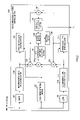
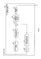
- FIG. 3 is a block diagram showing the configuration inside noise period detecting section 135 .
- Noise period detecting section 135 is provided with LPC analyzing section 151 , energy calculating section 152 , inactive speech determining section 153 , pitch analyzing section 154 and noise determining section 155 .
- LPC analyzing section 151 performs a linear prediction analysis with respect to an input speech signal and outputs a square mean value of the linear prediction residue acquired in the process of the linear prediction analysis.
- a square mean value itself of the linear prediction residue is acquired as a byproduct of the linear prediction analysis.
- Energy calculating section 152 calculates the energy of input speech signal on a per frame basis, and outputs the results as speech signal energy to inactive speech determining section 153 .
- Inactive speech determining section 153 compares the speech signal energy received as input from energy calculating section 152 with a predetermined threshold, and, if the speech signal energy is less than the predetermined threshold, determines that the speech signal is inactive speech, and, if the speech signal energy is equal to or greater than the threshold, determines that the speech signal in a frame of the encoding target is active speech, and outputs the inactive speech determining result to noise determining section 155 .
- Pitch analyzing section 154 performs a pitch analysis with respect to the input speech signal and outputs the pitch prediction gain to noise determining section 155 .
- a pitch prediction analysis finds T and gp minimizing ⁇
- 2 , n 0, . . . , L ⁇ 1.
- L is the frame length
- T is the pitch lag
- gp is the pitch gain
- gp ⁇ x(n) ⁇ x(n ⁇ T)/ ⁇ x(n ⁇ T) ⁇ x(n ⁇ T)
- n 0, . . . , L ⁇ 1 holds.
- a pitch prediction gain is expressed by (a square mean value of the speech signal)/(a square mean value of the pitch prediction residue), and is also expressed by 1/(1 ⁇ (
- Noise determining section 155 determines, on a per frame basis, whether the input speech signal is a noise period or speech period, using the square mean value of a linear prediction residue received as input from LPC analyzing section 151 , the inactive speech determination result received as input from inactive speech determining section 153 and the pitch prediction gain received as input from pitch analyzing section 154 , and outputs the determination result as a noise period detection result to high band noise level updating section 136 and low band noise level updating section 137 .
- noise determining section 155 determines that the input speech signal is a noise period, and otherwise determines that the input speech signal is a speech period.
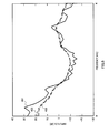
- FIG. 4 illustrates an effect acquired by shaping quantization noise with respect to a speech signal in a speech period in which speech is predominant over background noise, using speech encoding apparatus 100 according to the present embodiment.
- solid line graph 301 shows an example of a speech signal spectrum in a speech period in which speech is predominant over background noise.
- a speech signal a speech signal of “HΔ as in “K ⁇ HΔ pronounced by a woman, is exemplified.
- dotted line graph 302 shows the resulting quantization noise spectrum.
- dashed line graph 303 shows the resulting quantization noise spectrum.
- the difference between the low band SNR and the high band SNR is substantially equivalent to the difference between the low band component energy and the high band component energy.
- the low band component energy is higher than the high band component energy, and, consequently, the low band SNR is higher than the high band SNR.
- speech encoding apparatus 100 with tilt compensation coefficient control section 103 shapes the high band components of the quantization noise higher.
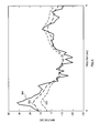
- FIG. 5 illustrates an effect acquired by shaping quantization noise with respect to a speech signal in a noise-speech superposition period in which background noise such as car noise and speech are superposed on one another, using speech encoding apparatus 100 according to the present embodiment.
- solid line graph 401 shows a spectrum example of a speech signal in a noise-speech superposition period in which background noise and speech are superposed on one another.
- a speech signal a speech signal of “HΔ as in “K ⁇ HΔ pronounced by a woman, is exemplified.
- Dashed line graph 402 shows the spectrum of quantization noise spectrum which speech encoding apparatus 100 without tilt compensation coefficient control section 103 acquires by shaping the quantization noise.
- Dashed line graph 403 shows the spectrum of quantization noise acquired upon shaping the quantization noise using speech encoding apparatus 100 according to the present embodiment.
- the high band SNR is higher than the low band SNR.
- speech encoding apparatus 100 with tilt compensation coefficient control section 103 shapes the low band components of the quantization noise higher. That is, as shown in dotted line graph 402 and dashed line 403 , when quantization noise is shaped with respect to a speech signal in a noise-speech superposition period using speech encoding apparatus 100 according to the present embodiment, it is possible to suppress the high band parts of the quantization noise spectrum more than when a speech encoding apparatus without tilt compensation coefficient control section 103 is used.
- the adjustment function for the spectral slope of quantization noise is further compensated using a synthesis filter comprised of tilt compensation coefficient ⁇ 3 , so that it is possible to adjust the spectral slope of quantization noise without changing formant weighting.
- tilt compensation coefficient ⁇ 3 is calculated using a function about the difference between the low band SNR and high band SNR of the speech signal, and a threshold for tilt compensation coefficient ⁇ 3 is controlled using the energy of background noise of the speech signal, so that it is possible to perform perceptual weighting filtering suitable for speech signals in a noise-speech superposition period in which background noise and speech are superposed on one another.
- a filter expressed by 1/(1 ⁇ 3 z ⁇ 1 ) is used as a tilt compensation filter
- the value of ⁇ 3 can be changed adaptively and used.
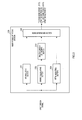
- FIG. 6 is a block diagram showing the main components of speech encoding apparatus 200 according to Embodiment 2 of the present invention.
- speech encoding apparatus 200 is provided with LPC analyzing section 101 , LPC quantizing section 102 , tilt compensation coefficient control section 103 and multiplexing section 109 , which are similar to in speech encoding apparatus 100 (see FIG. 1 ) shown in Embodiment 1, and therefore explanations of these sections will be omitted.
- Speech encoding apparatus 200 is further provided with a i ′ calculating section 201 , a i ′′ calculating section 202 , a i ′′′ calculating section 203 , inverse filter 204 , synthesis filter 205 , perceptual weighting filter 206 , synthesis filter 207 , synthesis filter 208 , excitation search section 209 and memory updating section 210 .
- synthesis filter 207 and synthesis filter 208 form impulse response generating section 260 .
- a i ′ calculating section 201 calculates weighted linear prediction coefficients a i ′ according to following equation 11 using linear prediction coefficients a i received as input from LPC analyzing section 101 , and outputs the calculated a i ′ to perceptual weighting filter 206 and synthesis filter 207 .
- ⁇ 1 represents the first formant weighting coefficient.
- the weighting linear prediction coefficients a i ′ is used for perceptual weighting filtering in perceptual weighting filter 206 which will be described later.
- a i ′′ calculating section 202 calculates weighted linear prediction coefficients a i ′′ according to following equation 12 using a linear prediction coefficient a i received as input from LPC analyzing section 101 , and outputs the calculated a i ′′ to a i ′′′ calculating section 203 .
- the weighted linear prediction coefficients a i ′′ are used in perceptual weighting filter 105 in FIG. 1 , in this case, the weighted linear prediction coefficients a i ′′ are used to only calculate weighted linear prediction coefficients a i ′′′ containing tilt compensation coefficient ⁇ 3 .
- ⁇ 2 represents the second formant weighting coefficient.
- a i ′′′ calculating section 203 calculates weighted linear prediction coefficients a i ′′′ according to following equation 13 using a tilt compensation coefficient ⁇ 3 received as input from tilt compensation coefficient control section 103 and the a i ′′ received as input from a i ′′ calculating section 202 , and outputs the calculated a i ′′′ to perceptual weighting filter 206 and synthesis filter 208 .
- ⁇ 3 represents the tilt compensation coefficient.
- the weighted linear prediction coefficient a i ′′′ includes tilt compensation coefficient and is used in perceptual weighting filtering in perceptual weighting filter 206 .
- Inverse filter 204 performs inverse filtering of an input speech signal using the transfer function shown in following equation 14 including quantized linear prediction coefficients a ⁇ i received as input from LPC quantizing section 102 .
- the signal acquired by inverse filtering in inverse filter 204 is a linear prediction residue signal calculated using a quantized linear prediction coefficients a ⁇ i .
- Inverse filter 204 outputs the resulting residue signal to synthesis filter 205 .
- Synthesis filter 205 performs synthesis filtering of the residue signal received as input from inverse filter 204 using the transfer function shown in following equation 15 including quantized linear prediction coefficients a ⁇ i received as input from LPC quantizing section 102 .
- synthesis filter 205 uses as a filter state the first error signal fed back from memory updating section 210 which will be described later.
- a signal acquired by synthesis filtering in synthesis filter 205 is equivalent to a synthesis signal from which a zero input response signal is removed.
- Synthesis filter 205 outputs the resulting synthesis signal to perceptual weighting filter 206 .
- Perceptual weighting filter 206 is formed with an inverse filter having the transfer function shown in following equation 16 and synthesis filter having the transfer function shown in following equation 17, and is a pole-zero type filter. That is, the transfer function in perceptual weighting filter 206 is expressed by following equation 18.
- a i ′ represents the weighting linear prediction coefficient received as input from a i ′ calculating section 201
- a i ′′′ represents the weighting linear prediction coefficient containing tilt compensation coefficient ⁇ 3 received as input from a i ′′′ calculating section 203
- Perceptual weighting filter 206 performs perceptual weighting filtering with respect to the synthesis signal received as input from synthesis filter 205 , and outputs the resulting target signal to excitation search section 209 and memory updating section 210 . Further, perceptual weighting filter 206 uses as a filter state a second error signal fed back from memory updating section 210 .
- Synthesis filter 207 performs synthesis filtering with respect to the weighting linear prediction coefficients a i ′ received as input from a i ′ calculating section 201 using the same transfer function as in synthesis filter 205 , that is, using the transfer function shown in above-described equation 15, and outputs the synthesis signal to synthesis filter 208 .
- the transfer function shown in equation 15 includes quantized linear prediction coefficients a ⁇ i received as input from LPC quantizing section 102 .
- Synthesis filter 208 further performs synthesis filtering with respect to the synthesis signal received as input from synthesis filter 207 , that is, performs filtering of a pole filter part of the perceptual weighting filtering, using the transfer function shown in above-described equation 17 including weighted linear prediction coefficients a i ′′′ received as input from a i ′′′ calculating section 203 .
- a signal acquired by synthesis filtering in synthesis filter 208 is equivalent to a perceptual weighted impulse response signal.
- Synthesis filter 208 outputs the resulting perceptual weighted impulse response signal to excitation search section 209 .
- Excitation search section 209 is provided with a fixed codebook, adaptive codebook, gain quantizer and such, receives as input the target signal from perceptual weighting filter 206 and the perceptual weighted impulse response signal from synthesis filter 208 . Excitation search section 209 searches for an excitation signal minimizing error between the target signal and the signal acquired by convoluting the perceptual weighted impulse response signal with the searched excitation signal. Excitation search section 209 outputs the searched excitation signal to memory updating section 210 and outputs the encoding parameter of the excitation signal to multiplexing section 109 . Further, excitation search section 209 outputs a signal, which is acquired by convoluting the perceptual weighted impulse response signal with the excitation signal, to memory updating section 210 .
- Memory updating section 210 incorporates the same synthesis filter as synthesis filter 205 , drives the internal synthesis filter using the excitation signal received as input from excitation search section 209 , and, by subtracting the resulting signal from the input speech signal, calculates the first error signal. That is, an error signal is calculated between an input speech signal and a synthesis speech signal synthesized using the encoding parameter. Memory updating section 210 feeds back the calculated first error signal as a filter state, to synthesis filter 205 and perceptual weighting filter 206 .
- memory updating section 210 calculates a second error signal by subtracting the signal acquired by superposing a perceptual weighted impulse response signal over the speech signal received as input from excitation search section 209 , from the target signal received as input from perceptual weighting filter 206 . That is, an error signal is calculated between the perceptual weighting input signal and a perceptual weighting synthesis speech signal synthesized using the encoding parameter. Memory updating section 210 feeds back the calculated second error signal as a filter state to perceptual weighting filter 206 .
- perceptual weighting filter 206 is a cascade connection filter formed with the inverse filter represented by equation 16 and the synthesis filter represented by equation 17, and the first error signal and the second error signal are used as the filter state in the inverse filter and the filter state in the synthesis filter, respectively.
- Speech encoding apparatus 200 employs a configuration acquired by changing speech encoding apparatus 100 shown in Embodiment 1.
- perceptual weighting filters 105 - 1 to 105 - 3 of speech encoding apparatus 100 are equivalent to perceptual weighting filter 206 of speech encoding apparatus 200 .
- equation 19 is an equation developed from a transfer function to show that perceptual weighting filters 105 - 1 to 105 - 3 100 are equivalent to perceptual weighting filter 206 .
- a synthesis filter having the transfer function shown in above-described equation 17 in perceptual weighting filter 206 is equivalent to a filter having a cascade connection of the transfer functions shown in following equations 21 and 22 in perceptual weighting filters 105 - 1 to 105 - 3 .
- perceptual weighting filter 206 is formed with two filters having respective transfer functions represented by equations 16 and 17, and the number of filters is smaller by one than perceptual weighting filters 105 - 1 to 105 - 3 formed with three filters having respective transfer functions represented by equations 20, 21 and 22, so that it is possible to simplify processing. Further, for example, if two filters are combined to one, intermediate variables generated in two filter processing needs not be generated, whereby the filter state needs not be held upon generating the intermediate variables, so that updating the filter state becomes easier.
- the number of filters forming speech encoding apparatus 200 according to the present embodiment is six, and the number of filters forming speech encoding apparatus 100 shown in Embodiment 1 is eleven, and therefore the difference between these numbers is five.
- the number of filtering processing decreases, so that it is possible to adaptively adjust the spectral slope of quantization noise without changing formant weighting, and simplify speech encoding processing and prevent degradation of encoding performance caused by degradation of precision of computations.
- FIG. 7 is a block diagram showing the main components of speech encoding apparatus 300 according to Embodiment 3 of the present invention.
- speech encoding apparatus 300 has the similar basic configuration to speech encoding apparatus 100 (see FIG. 1 ) shown in Embodiment 1, and the same components will be assigned the same reference numerals and explanations will be omitted.
- LPC analyzing section 301 tilt compensation coefficient control section 303 and excitation search section 307 of speech encoding apparatus 300 and LPC analyzing section 101
- tilt compensation coefficient control section 103 and excitation search section 107 of speech encoding apparatus 100 in part of processing, and, to show the difference, a different reference numerals are assigned and only these sections will be explained below.
- LPC analyzing section 301 differs from LPC analyzing section 101 shown in Embodiment 1 only in outputting the square mean value of linear prediction residue acquired in the process of linear prediction analysis with respect to an input speech signal, to tilt compensation coefficient control section 303 .
- Excitation search section 307 differs from excitation search section 107 shown in Embodiment 1 only in calculating a pitch prediction gain expressed by
- 2 /( ⁇ x(n)x(n) ⁇ y(n)y(n)), n 0, 1, . . . , L ⁇ 1, in the search process of an adaptive codebook, and outputting the pitch prediction gain to tilt compensation coefficient control section 303 .
- x(n) is the target signal for an adaptive codebook search, that is, the target signal received as input from adder 106 .
- y(n) is the signal superposing the impulse response signal of a perceptual weighting synthesis filter (which is a cascade connection filter formed with a perceptual weighting filter and synthesis filter), that is, the perceptual weighted impulse response signal received as input from perceptual weighting filter 105 - 3 , over the excitation signal received as input from the adaptive codebook.
- a perceptual weighting synthesis filter which is a cascade connection filter formed with a perceptual weighting filter and synthesis filter
- excitation search section 107 shown in Embodiment 1 also calculates two terms of
- FIG. 8 is a block diagram showing the configuration inside tilt compensation coefficient control section 303 according to Embodiment 3 of the present invention. Further, tilt compensation coefficient control section 303 has a similar configuration to tilt compensation coefficient control section 103 (see FIG. 2 ) shown in Embodiment 1, and the same components will be assigned the same reference numerals and explanations will be omitted.
- Noise period detecting section 335 does not receive as input a speech signal, and detects a noise period of an input speech signal on a per frame basis, using the square mean value of linear prediction residue received as input from LPC analyzing section 301 , pitch prediction gain received as input from excitation search section 307 , energy level of high band components of speech signal received as input from high band energy level calculating section 132 and energy level of low band components of speech signal received as input from low band energy level calculating section 134 .
- FIG. 9 is a block diagram showing the configuration inside noise period detecting section 335 according to Embodiment 3 of the present invention.
- Inactive speech determining section 353 determines on a per frame basis whether an input speech signal is inactive speech or active speech, using the energy level of high band components of speech signal received as input from high band energy level calculating section 132 and energy level of low band components of speech signal received as input from low band energy level calculating section 134 , and outputs the inactive speech determination result to noise determining section 355 .
- inactive speech determining section 353 determines that the input speech signal is inactive speech when the sum of the energy level of high band components of speech signal and energy level of low band components of speech signal is less than a predetermined threshold, and determines that the input speech signal is active speech when the above-noted sum is equal to or greater than the predetermined threshold.
- a threshold for the sum of the energy level of high band components of speech signal and energy level of low band components of speech signal for example, 2 ⁇ 10 log 10 (32 ⁇ L), where L is the frame length, is used.
- Noise determining section 355 determines on a per frame basis whether an input speech signal is a noise period or a speech period, using the square mean value of linear prediction residue received as input from linear analyzing section 301 , inactive speech determination result received as input from inactive speech determining section 353 and pitch prediction gain received as input from excitation search section 307 , and outputs the determination result as a noise period detection result to high band noise level updating section 136 and low band noise level updating section 137 .
- noise determining section 355 determines that the input speech signal is a noise period, and, otherwise, determines that the input speech signal is a speech period.
- 0.1 is used as a threshold for the square mean value of linear prediction residue
- 0.4 is used as a threshold for the pitch prediction gain.
- noise period detection is performed using the square mean value of linear prediction residue and pitch prediction gain generated in the LPC analysis process in speech encoding and the energy level of high band components of speech signal and energy level of low band components of speech signal generated in the calculation process of a tilt compensation coefficient, so that it is possible to suppress the amount of calculations for noise period detection and perform spectral tilt compensation of quantization noise without increasing the overall amount of calculations in speech encoding.
- the present invention is not limited to this.
- a linear prediction analysis it is possible to execute the Levinson Durbin algorithm after normalizing the autocorrelation function of an input signal by the autocorrelation function maximum value, and the square mean value of linear prediction residue acquired in this process is a parameter showing a linear prediction gain and may be referred to as the normalized prediction residue power of the linear prediction analysis (here, the inverse number of the normalized prediction residue power corresponds to a linear prediction gain).
- the pitch prediction gain according to the present embodiment may be referred to as normalized cross-correlation.
- the present invention is not limited to this, and, to find a more reliable detection result in a noise period, it is possible to use square mean values of the linear prediction residue and pitch prediction gain smoothed between frames.
- high band energy level calculating section 132 and low band energy level calculating section 134 calculate the energy level of high band components of speech signal and energy level of low band components of speech signal according to equations 5 and 6, respectively
- the present invention is not limited to this, and it is possible to further add bias such as 4 ⁇ 2 ⁇ L (where L is the frame length) such that the calculated energy level is not made a value close to zero.
- high band noise level updating section 136 and low band noise level updating section 137 use the energy level of high band components of speech signal and energy level of low band components of speech signal with bias as above.
- the speech encoding apparatus according to Embodiment 4 of the present invention has the same components as in speech encoding apparatus 300 according to Embodiment 3 of the present invention and perform the same basic operations, and therefore will not be shown and detailed explanations will be omitted.
- tilt compensation coefficient control section 403 of the speech encoding apparatus according to the present embodiment and tilt compensation coefficient control section 303 of speech encoding apparatus 300 according to Embodiment 3 in part of processing, and the different reference numeral is assigned to show the differences. Only tilt compensation coefficient control section 403 will be explained below.
- FIG. 10 is a block diagram showing the configuration inside tilt compensation coefficient control section 403 according to Embodiment 4 of the present invention.
- tilt compensation coefficient control section 403 has the similar basic configuration to tilt compensation coefficient control section 303 (see FIG. 8 ) shown in Embodiment 3, and differs from tilt compensation coefficient control section 303 in providing counter 461 .
- noise period detecting section 435 of tilt compensation coefficient control section 403 and noise period detecting section 335 of tilt compensation coefficient control section 303 in receiving as input a high band SNR and low band SNR from adders 138 and 139 , respectively, and in part of processing, and the different reference numerals are assigned to show the differences.
- Counter 461 is formed with the first counter and second counter, and updates the values on the first counter and second counter using noise period detection results received as input from noise period detecting section 435 and feeds back the updated values on the first counter and second counter to noise period detecting section 435 .
- the first counter counts the number of frames determined consecutively as noise periods
- the second counter counts the number of frames determined consecutively as speech periods.
- the first counter is incremented by one and the second counter is reset to zero.
- the second counter is incremented by one. That is, the first counter shows the number of frames determined as noise periods in the past, and the second counter shows how many frames have been successively determined as speech periods.
- FIG. 11 is a block diagram showing the configuration inside noise period detecting section 435 according to Embodiment 4 of the present invention. Further, noise period detecting section 435 has the similar basic configuration to noise period detecting section 335 (see FIG. 9 ) shown in Embodiment 3 and performs the same basic operations. However, there are differences between noise determining section 455 of noise period detecting section 435 and noise determining section 355 of noise period detecting section 335 in part of processing, and the different reference numerals are assigned to show the differences.
- Noise determining section 455 determines on a per frame basis whether an input speech signal is a noise period or a speech period, using the values on the first counter and second counter received as input from counter 461 , square mean value of linear prediction residue received as input from LPC analyzing section 301 , inactive speech determination result received as input from inactive speech determining section 353 , the pitch prediction gain received as input from excitation search section 307 and high band SNR and low band SNR received as input from adders 138 and 139 , and outputs the determination result as a noise period detection result, to high band noise level updating section 136 and low band noise level updating section 137 .
- noise determining section 455 determines that the input speech signal is a noise period, and otherwise determines that the input speech signal is a speech period.
- 100 is used as a threshold for the value on the first counter
- 10 is used as a threshold for the value on the second counter
- 5 dB is used as a threshold for the high band SNR and low band SNR.
- noise determining section 455 determines that the input speech signal is not in a noise period but is a speech period. As a reason for this, there is a high possibility that meaningful speech signals are present in addition to background noise in a frame of a high SNR, and, consequently, the frame needs not be determined as a noise period.
- noise determining section 455 performs a determination only by a determination reference in noise determining section 355 shown in Embodiment 3, and does not use the above-noted SNR for a noise period determination. Further, although the noise period determination using the above-noted SNR is effective to detect onset of speech, if this determination is used frequently, the period that should be determined as noise may be determined as a speech period.
- onset period of speech namely, immediately after a noise period switches to a speech period, that is, when the value on the second counter is less than a predetermined threshold
- noise period determination it is preferable to limit the use of noise period determination.
- a noise period is detected using the number of frames determined consecutively as a noise period or speech period in the past and the high band SNR and low band SNR of a speech signal, so that it is possible to improve the accuracy of noise period detection and improve the accuracy of spectral tilt compensation for quantization noise.
- Embodiment 5 of the present invention a speech encoding method will be explained for adjusting the spectral slope of quantization noise and performing adaptive perceptual weighting filtering suitable for a noise-speech superposition period in which background signals and speech signals are superposed on one another, in AMR-WB (adaptive multirate-wideband) speech encoding.
- AMR-WB adaptive multirate-wideband
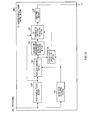
- FIG. 12 is a block diagram showing the main components of speech encoding apparatus 500 according to Embodiment 5 of the present invention.
- Speech encoding apparatus 500 shown in FIG. 12 is equivalent to an AMR-WB encoding apparatus adopting an example of the present invention.
- speech encoding apparatus 500 has a similar configuration to speech encoding apparatus 100 (see FIG. 1 ) shown in Embodiment 1, and the same components will be assigned the same reference numerals and explanations will be omitted.
- Speech encoding apparatus 500 differs from speech encoding apparatus 100 shown in Embodiment 1 in further having pre-emphasis filter 501 . Further, there are differences between tilt compensation coefficient control section 503 and perceptual weighting filters 505 - 1 to 505 - 3 of speech encoding apparatus 500 and tilt compensation coefficient control section 103 and perceptual weighting filters 105 - 1 to 105 - 3 of speech encoding apparatus 100 in part of processing, and, consequently, the different reference numerals are assigned to show the differences. Only these differences will be explained below.
- Tilt compensation coefficient control section 503 calculates tilt compensation coefficient ⁇ 3 ′′ for adjusting the spectral slope of quantization noise using the input speech signal subjected to filtering in pre-emphasis filter 501 , and outputs the tilt compensation coefficient ⁇ 3 ′′ to perceptual weighting filters 505 - 1 to 505 - 3 . Further, tilt compensation coefficient control section 503 will be described later in detail.
- Perceptual weighting filters 505 - 1 to 505 - 3 are different from perceptual weighting filters 105 - 1 to 105 - 3 shown in Embodiment 1 only in performing perceptual weighting filtering with respect to the input speech signal subjected to filtering in pre-emphasis filter 501 , using the transfer function shown in following equation 24 including the linear prediction coefficients a i received as input from LPC analyzing section 101 and tilt compensation coefficient ⁇ 3 ′′ received as input from tilt compensation coefficient control section 503 .
- FIG. 13 is a block diagram showing the configuration inside tilt compensation coefficient control section 503 .
- Low band energy level calculating section 134 , noise period detecting section 135 , low band noise level updating section 137 , adder 139 and smoothing section 145 provided by tilt compensation coefficient control section 503 are equivalent to low band energy level calculating section 134 , noise period detecting section 135 , low band noise level updating section 137 , adder 139 and smoothing section 145 provided by tilt compensation coefficient control section 103 (see FIG. 1 ) shown in Embodiment 1, and therefore explanations will be omitted.
- LPF 533 extracts low band components less than 1 kHz in the frequency domain of an input speech signal subjected to filtering in pre-emphasis filter 503 , and outputs the low band components of speech signal to low band energy level calculating section 134 .
- Tilt compensation coefficient calculating section 541 calculates the tilt compensation coefficient ⁇ 3 ′′ as shown in FIG. 14 , and outputs the tilt compensation coefficient ⁇ 3 ′′ to smoothing section 145 .
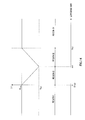
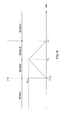
- FIG. 14 illustrates a calculation of the tilt compensation coefficient ⁇ 3 ′′ in tilt compensation coefficient calculating section 541 .
- tilt compensation coefficient calculating section 541 when the low band SNR is less than 0 dB (i.e., in region I), or when the low band SNR is equal to or greater than Th2 dB (i.e., in region IV), tilt compensation coefficient calculating section 541 outputs K max as ⁇ 3 ′′. Further, tilt compensation coefficient calculating section 541 calculates ⁇ 3 ′′ according to following equation 25 when the low band SNR is equal to or greater than 0 and less than Th1 (i.e., in region II), and calculates ⁇ 3 ′ according to following equation 26 when the low band SNR is equal to or greater than Th1 and less than Th2 (i.e., in region III).
- K max is the value of constant tilt compensation coefficient ⁇ 3 ′′ used in perceptual weighting filters 505 - 1 to 505 - 3 . Further, K min and K max are constants holding 0 ⁇ K min ⁇ K max ⁇ 1.
- region I shows a period in which only background noise is present without speech in an input speech signal
- region II shows a period in which background noise is predominant over speech in an input speech signal
- region III shows a period in which speech is predominant over background noise in an input speech signal
- region IV shows a period in which only speech is present without background noise in an input speech signal.
- tilt compensation coefficient calculating section 541 makes the value of tilt compensation coefficient ⁇ 3 ′′ larger in the range between K min and K max when the low band SNR decreases.
- a background signal is predominant, that is, a background signal itself is the target to be listened, and that, in this case, noise shaping which collects quantization noise in low frequencies should be avoided.
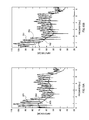
- FIG. 15A and FIG. 15B illustrate an effect acquired by shaping quantization noise using speech encoding apparatus 500 according to the present embodiment.
- these figures illustrate the spectrum of the vowel part in the sound of “SO” as in “SOUCHOU,” pronounced by a woman.
- a background noise (car noise) is added in FIG. 15B .
- FIG. 15A illustrates an effect acquired by shaping quantization noise with respect to a speech signal in which there is only speech and there is substantially no background noise, that is, with respect to a speech signal of the low band SNR associated with region IV of FIG. 14 .
- FIG. 15A illustrates an effect acquired by shaping quantization noise with respect to a speech signal in which there is only speech and there is substantially no background noise, that is, with respect to a speech signal of the low band SNR associated with region IV of FIG. 14 .
- 15B illustrates an effect acquired upon shaping quantization noise with respect to a speech signal in which background noise (referred to as “car noise”) and speech are superposed on one another, that is, with respect to a speech signal of the low band SNR associated with region II or region III in FIG. 14 .
- car noise background noise
- solid lines graphs 601 and 701 show spectrum examples of speech signals in the same speech period that are different only in an existence or non-existence of background noise.
- Dotted line graphs 602 and 702 show quantization noise spectrums acquired upon shaping quantization noise using speech encoding apparatus 500 without tilt compensation coefficient control section 503 .
- Dashed line graphs 603 and 703 show quantization noise spectrums acquired upon shaping quantization noise using speech encoding apparatus 500 according to the present embodiment.
- graphs 603 and 703 showing quantized error spectrum envelopes differ from each other, depending on whether background noise is present.
- graphs 602 and 603 are substantially the same. The reason is that, in region IV shown in FIG. 14 , tilt compensation coefficient calculating section 541 outputs K max as ⁇ 3 ′′ to perceptual weighting filters 505 - 1 to 505 - 3 . Further, as described above, if speech encoding apparatus 500 is not provided with tilt compensation coefficient control section 503 , K max is the value of constant tilt compensation coefficient ⁇ 3 ′′ used in perceptual weighting filters 505 - 1 to 505 - 3 .
- the characteristics of a car noise signal includes that the energy is concentrated at low frequencies and the low band SNR decreases.
- the low band SNR of speech signal shown in graph 701 in FIG. 15B corresponds to region II and region III shown in FIG. 14 .
- tilt compensation coefficient calculating section 541 calculates the tilt compensation coefficient ⁇ 3 ,′′ which is a smaller value than K max .
- the quantized error spectrum is as represented by graph 703 that increases in the lower band.
- the slope of the perceptual weighting filter is controlled to further allow low band quantization noise.
- the tilt compensation coefficient ⁇ 3 ′′ is further increased when the low band SNR is lower, and, if the low band SNR is equal to or greater than a threshold, the tilt compensation coefficient ⁇ 3 ′′ is further increased when the low band SNR is higher. That is, a control method of the tilt compensation coefficient ⁇ 3 ′′ is switched according to whether a background noise or a speech signal is predominant, so that it is possible to adjust the spectral slope of quantization noise such that noise shaping suitable for a predominant signal amongst signals included in an input signal is possible.
- tilt compensation coefficient ⁇ 3 ′′ shown in FIG. 14 is calculated in tilt compensation coefficient calculating section 541
- a limit of the upper limit value and lower limit value is provided with respect to the calculated tilt compensation coefficient ⁇ 3 ′′.
- speech encoding apparatus 500 is not provided with tilt compensation coefficient control section 503 , it is possible to use the value of constant tilt compensation coefficient ⁇ 3 ′′ used in perceptual weighting filters 505 - 1 to 505 - 3 , as the upper limit value.
- FIG. 16 is a block diagram showing the main components of speech encoding apparatus 600 according to Embodiment 6 of the present embodiment.
- Speech encoding apparatus 600 shown in FIG. 16 has a similar configuration to speech encoding apparatus 500 (see FIG. 12 ) shown in Embodiment 5, and the same components will be assigned the same reference numerals and explanations will be omitted.
- Speech encoding apparatus 600 is different from speech encoding apparatus 500 shown in Embodiment 5 in providing weight coefficient control section 601 instead of tilt compensation coefficient control section 503 . Further, there are differences between perceptual weighting filters 605 - 1 to 605 - 3 of speech encoding apparatus 600 and perceptual weighting filters 505 - 1 to 505 - 3 of speech encoding apparatus 500 in part of processing, and, consequently, the different reference numerals are assigned. Only these differences will be explained below.
- Weight coefficient control section 601 calculates a weight coefficient a ⁇ i using an input speech signal after filtering in pre-emphasis filter 501 , and outputs the a ⁇ i to perceptual weighting filters 605 - 1 to 605 - 3 . Further, weight coefficient control section 601 will be described later in detail.
- Perceptual weighting filters 605 - 1 to 605 - 3 are different from perceptual weighting filters 505 - 1 to 505 - 3 shown in Embodiment 5 only in performing perceptual weighing filtering with respect to the input speech signal after filtering in pre-emphasis filter 501 , using the transfer function shown in following equation 27 including constant tilt compensation coefficient ⁇ 3 ′′, linear prediction coefficients a i received as input from LPC analyzing section 101 and weight coefficients a ⁇ i received as input from weight coefficient control section 601 .
- FIG. 17 is a block diagram showing the configuration inside weight coefficient control section 601 according to the present embodiment.
- weight coefficient control section 601 is provided with noise period detecting section 135 , energy level calculating section 611 , noise LPC updating section 612 , noise level updating section 613 , adder 614 and weight coefficient calculating section 615 .
- noise period detecting section 135 is equivalent to noise period detecting section 135 of tilt compensation coefficient calculating section 103 (see FIG. 2 ) shown in Embodiment 1.
- Energy level calculating section 611 calculates the energy level of the input speech signal after pre-emphasis in pre-emphasis filter 501 on a per frame basis, according to following equation 28, and outputs the speech signal energy level to noise level updating section 613 and adder 614 .
- E 10 log 10 (
- E is a decibel representation of
- Noise LPC updating section 612 finds the average value of linear prediction coefficients a i in noise periods received as input from LPC analyzing section 101 , based on the noise period determining result in noise period detecting section 135 .
- linear prediction coefficients a i received as input are converted into LSF (Line Spectral Frequency) or ISF (Immittance Spectral Frequency), which are frequency domain parameters, and the average value of LSF or ISF in noise periods is calculated and outputted to weight coefficient calculating section 615 .
- Fave is the average values of ISF or LSF in noise periods
- ⁇ is the smoothing coefficient
- F is the ISF or LSF in frames (or subframes) determined as noise periods (i.e., ISF or LSF acquired by converting linear prediction coefficients a i received as input).
- noise LPC updating section 612 needs not perform processing for converting linear prediction coefficients a i to ISF or LSF.
- Noise level updating section 613 holds the average energy level of background noise, and, upon receiving as input background noise period detection information from noise period detecting section 135 , updates the average energy level of background noise held using the speech signal energy level received as input from energy level calculating section 611 .
- updating is performed according to, for example, following equation 29.
- E N ⁇ E N +(1 ⁇ ) E (Equation 29)
- E represents the speech signal energy level received as input from energy level calculating section 611 .
- background noise period detection information is received as input from noise period detecting section 135 to noise level updating section 613 , it shows that the input speech signal is comprised of only background noise periods, and the speech signal energy level received as input from energy level calculating section 611 to noise level updating section 613 , that is, E shown in the above-noted equation is the background noise energy level.
- E N represents the average energy level of background noise held in noise level updating section 613 and ⁇ is the long term smoothing coefficient where O ⁇ 1.
- Noise level updating section 613 outputs the average energy level of background noise held to adder 614 .
- Adder 614 subtracts the average energy level of background noise received as input from noise level updating section 613 , from the speech signal energy level received as input from energy level calculating section 611 , and outputs the subtraction result to weight coefficient calculating section 615 .
- the subtraction result acquired in adder 614 shows the difference between two energy levels represented by logarithm, that is, the subtraction result shows the difference between the speech signal energy level and the average energy level of background noise. Consequently, the subtraction result shows a ratio of these two energies, that is, a ratio between the speech signal energy and the long term average energy of background noise signal.
- the subtraction result acquired in adder 614 is the speech signal SNR.
- Weight coefficient calculating section 615 calculates a weight coefficient a ⁇ i using the SNR received as input from adder 614 and the average ISF or LSF in noise periods received as input from noise LPC updating section 612 , and outputs the weight coefficient a ⁇ i to perceptual weighting filters 605 - 1 to 605 - 3 .
- weight coefficient calculating section 615 acquires S ⁇ by performing short term smoothing of the SNR received as input from adder 614 , and further acquires L ⁇ i by performing short term smoothing of the average ISF or LSF in noise periods received as input from noise LPC updating section 612 .
- weight coefficient calculating section 615 acquires b i by converting L ⁇ i into the LPC (linear prediction coefficients) in the time domain.
- FIG. 18 illustrates a calculation of weight adjustment coefficient ⁇ in weight coefficient calculating section 615 .
- weight coefficient calculating section 615 makes the value of weight adjustment coefficient ⁇ “0” in region I and region IV. That is, in region I and region IV, the linear prediction inverse filter represented by following equation 30 is in the off state in perceptual weighting filters 605 - 1 to 605 - 3 .
- weight coefficient calculating section 615 calculates a weight adjustment coefficient ⁇ according to following equations 31 and 32.
- ⁇ SK max /Th 1 (Equation 31)
- ⁇ K max ⁇ K max ( S ⁇ Th 1)/( Th 2 ⁇ Th 1) (Equation 32)
- weight coefficient calculating section 615 makes the weight adjustment coefficient ⁇ larger when the SNR increases, and, if the speech signal SNR is less than TH1, makes the weight adjustment coefficient ⁇ smaller when the SNR decreases. Further, the weight coefficient a ⁇ i multiplying a linear prediction coefficient (LPC)b i showing the average spectrum characteristic in noise periods of the speech signal by the weight adjustment coefficient ⁇ i , is outputted to perceptual weighting filters 605 - 1 to 605 - 3 to form a linear prediction inverse filter.
- LPC linear prediction coefficient
- a weight coefficient is calculated by multiplying a linear prediction coefficient showing the average spectrum characteristic in noise periods of an input signal by a weight adjustment coefficient associated with the SNR of the speech signal, and the linear prediction inverse filter in a perceptual weighting filter is formed using this weight coefficient, so that it is possible to adjust the spectral envelope of quantization noise according to the spectrum characteristic of the input signal and improve sound quality of decoded speech.
- tilt compensation coefficient ⁇ 3 ′′ used in perceptual weighting filters 605 - 1 to 605 - 3 is a constant
- the present invention is not limited to this, and it is equally possible to further provide tilt compensation coefficient control section 503 shown in Embodiment 5 to speech encoding apparatus 600 and adjust the value of tilt compensation coefficient ⁇ 3 .′′
- the speech encoding apparatus (not shown) according to Embodiment 7 of the present invention has a basic configuration similar to speech encoding apparatus 500 shown in Embodiment 5, and is different from speech encoding apparatus 500 only in the configuration and processing operations inside tilt compensation coefficient control section 503 .
- FIG. 19 is a block diagram showing the configuration inside tilt compensation coefficient control section 503 according to Embodiment 7.
- tilt compensation coefficient control section 503 is provided with noise period detecting section 135 , energy level calculating section 731 , noise level updating section 732 , low band and high band noise level ratio calculating section 733 , low band SNR calculating section 734 , tilt compensation coefficient calculating section 735 and smoothing section 145 .
- noise period detecting section 135 and smoothing section 145 are equivalent to noise period detecting section 135 and smoothing section 145 provided by tilt compensation coefficient control section 503 according to Embodiment 5.
- Energy level calculating section 731 calculates the energy level of an input speech signal after filtering in pre-emphasis filter 501 in more than two frequency bands, and outputs the calculated energy levels to noise level updating section 732 and low band SNR calculating section 734 .
- energy level calculating section 731 calculates, on a per frequency band basis, the energy level of the input speech signal converted into a frequency domain signal using DFT (Discrete Fourier Transform), FFT (Fast Fourier Transform) and such.
- DFT Discrete Fourier Transform
- FFT Fast Fourier Transform
- Noise level updating section 732 holds the average energy level of background noise in the low band and average energy level of background noise in the high band. Upon receiving as input background noise period detection information from noise period detecting section 135 , noise level updating section 732 updates the held average energy level of background noise in the low band and high band according to above-noted equation 29, using the speech signal energy level in the low band and high band received as input from energy level calculating section 731 . However, noise level updating section 732 performs processing in the low band and high band according to equation 29.
- E in equation 29 represents the speech signal energy level in the low band received as input from energy level calculating section 731 and E N represents the average energy level of background noise in the low band held in noise level updating section 732 .
- E in equation 29 represents the speech signal energy level in the high band received as input from energy level calculating section 731 and E N represents the average energy level of background noise in the high band held in noise level updating section 732 .
- Noise level updating section 732 outputs the updated average energy level of background noise in the low band and high band to low band and high band noise level ratio calculating section 733 , and outputs the updated average energy level of background noise in the low band to low band SNR calculating section 734 .
- Low band and high band noise level ratio calculating section 733 calculates a ratio in dB units between the average energy level of background noise in the low band and average energy level of background noise in the high band received as input from noise level updating section 732 , and outputs the result as a low band and high band noise level ratio to tilt compensation coefficient calculating section 735 .
- Low band SNR calculating section 734 calculates a ratio in dB units between the low band energy level of the input speech signal received as input from energy level calculating section 731 and the low band energy level of the background noise received as input from noise level updating section 732 , and outputs the ratio as the low band SNR to tilt compensation coefficient calculating section 735 .
- Tilt compensation coefficient calculating section 735 calculates tilt compensation coefficient ⁇ 3 ′′ using the noise period detection information received as input from noise period detecting section 135 , low band and high band noise level ratio received as input from low band and high band noise level ratio calculating section 733 and low band SNR received as input from low band SNR calculating section 734 , and outputs the tilt compensation coefficient ⁇ 3 ′′ to smoothing section 145 .
- FIG. 20 is a block diagram showing the configuration inside tilt compensation coefficient calculating section 735 .
- tilt compensation coefficient calculating section 735 is provided with coefficient modification amount calculating section 751 , coefficient modification amount adjusting section 752 and compensation coefficient calculating section 753 .
- Coefficient modification amount calculating section 751 calculates the amount of coefficient modification, which represents a modification degree of a tilt compensation coefficient, using the low band SNR received as input from low band SNR calculating section 734 , and outputs the calculated amount of coefficient modification to coefficient modification amount adjusting section 752 .
- the relationship between the low band SNR received as input and the amount of coefficient modification to be calculated is shown in, for example, FIG. 21 .
- FIG. 21 is equivalent to a figure acquired by seeing the horizontal axis in FIG. 18 as the low band SNR, seeing the vertical axis in FIG. 18 as the amount of coefficient modification and replacing the maximum value Kmax of weight coefficient ⁇ in FIG. 18 with the maximum value Kdmax in the amount of coefficient modification.
- coefficient modification amount calculating section 751 calculates the amount of coefficient modification as zero. By making the amount of coefficient modification in a noise period zero, inadequate modification of a tilt compensation coefficient in the noise period is prevented.
- Coefficient modification amount adjusting section 752 further adjusts the amount of coefficient modification received as input from coefficient modification amount calculating section 751 using the low band and high band level ratio received as input from low band and high band noise level ratio calculating section 733 .
- coefficient modification amount adjusting section 752 performs adjustment such that the amount of coefficient modification becomes smaller when the low band and high band noise level ratio decreases, that is, when the low band noise level becomes smaller than the high band noise level.
- D 2 ⁇ Nd ⁇ D 1(0 ⁇ Nd ⁇ 1) (Equation 33)
- D1 represents the amount of coefficient modification received as input from coefficient modification amount calculating section 751 and D2 represents the amount of coefficient modification adjusted.
- Nd represents the low band and high band noise level ratio received as input from low band and high band noise level ratio calculating section 733 .
- Compensation coefficient calculating section 753 compensates the default tilt compensation coefficient using the amount of coefficient modification received as input from coefficient modification amount adjusting section 752 , and outputs the resulting tilt compensation coefficient ⁇ 3 ′′ to smoothing section 145 .
- Kdefault represents the default tilt compensation coefficient.
- the default tilt compensation coefficient represents a constant tilt compensation coefficient used in perceptual weighting filters 505 - 1 to 505 - 3 even if the speech encoding apparatus according to the present embodiment is not provided with tilt compensation coefficient control section 503 .
- FIG. 22 is equivalent to a figure acquired by replacing Kmax in FIG. 14 with Kdefault and replacing Kmin in FIG. 14 with Kdefault ⁇ Nd ⁇ Kdmax.
- the low band and high band noise level ratio refers to information showing the spectral envelope of a background noise signal, and, when the low band and high band noise level ratio decreases, the spectral envelope of background noise approaches a flat, or convexes/concaves are present in the spectral envelope of background noise in a frequency band between the low band and the high band (i.e. middle band).
- coefficient modification amount adjusting section 752 performs adjustment such that the amount of coefficient modification is small.
- coefficient modification amount adjusting section 752 performs adjustment such that the amount of coefficient modification is large.
- the tilt compensation coefficient according to the SNR of an input speech signal and the low band and high band noise level ratio, it is possible to perform noise shaping associated with the spectral envelope of a background noise signal.
- noise period detecting section 135 may use output information from energy level calculating section 731 and noise level updating section 732 to detect a noise period. Further, processing in noise period detecting section 135 is shared in a voice activity detector (VAD) and background noise suppressor, and, if embodiments of the present invention are applied to a coder having processing sections such as a VAD processing section and background noise suppression processing section, it is possible to utilize output information from these processing sections. Further, if a background noise suppression processing section is provided, the background noise suppression processing section is generally provided with an energy level calculating section and noise level updating section and, consequently, part of processing in energy level calculating section 731 and noise level updating section 732 and processing in the background noise suppression processing may be common.
- VAD voice activity detector
- background noise suppression processing section is generally provided with an energy level calculating section and noise level updating section and, consequently, part of processing in energy level calculating section 731 and noise level updating section 732 and processing in the background noise suppression processing may be common.
- energy level calculating section 731 converts an input speech signal into a frequency domain signal to calculate the energy level in the low band and high band
- energy level calculating section 731 converts an input speech signal into a frequency domain signal to calculate the energy level in the low band and high band
- a coder that can perform background noise suppression processing such as spectrum subtraction
- energy level calculating section 731 may calculate the energy level by time domain signal processing using a high pass filter and low pass filter.
- compensation coefficient calculating section 753 may perform additional processing such as following equation 34 and further adjust modification amount D2 after adjustment.
- D 2 ′ ⁇ ′ ⁇ En ⁇ D 2(0 ⁇ ( ⁇ ′ ⁇ En ) ⁇ 1) (Equation 34)
- ⁇ ′ is the adjustment coefficient by which the background noise signal level En is multiplied, and uses, for example, 0.1.
- En may be the noise signal level in the whole band.
- this processing refers to processing for making the amount of modification D2 small in proportion to the background noise level.
- a signal illustrated as only passing within a block needs not pass the block every time. Further, in the drawings, even if a branch of the signal is likely to be performed inside the block, the signal needs not be branched in the block every time, and the branch of the signal may be performed outside the block.
- LSF and ISF can be referred to as LSP (Line Spectrum Pairs) and ISP (Immittance Spectrum Pairs), respectively.
- the speech encoding apparatus can be mounted on a communication terminal apparatus and base station apparatus in a mobile communication system, so that it is possible to provide a communication terminal apparatus, base station apparatus and mobile communication system having the same operational effect as above.
- the present invention can be implemented with software.
- the speech encoding method according to the present invention in a programming language, storing this program in a memory and making the information processing section execute this program, it is possible to implement the same function as the speech encoding apparatus of the present invention.
- each function block employed in the description of each of the aforementioned embodiments may typically be implemented as an LSI constituted by an integrated circuit. These may be individual chips or partially or totally contained on a single chip.
- LSI is adopted here but this may also be referred to as “IC,” “system LSI,” “super LSI,” or “ultra LSI” depending on differing extents of integration.
- circuit integration is not limited to LSI's, and implementation using dedicated circuitry or general purpose processors is also possible.
- FPGA Field Programmable Gate Array
- reconfigurable processor where connections and settings of circuit cells in an LSI can be reconfigured is also possible.
- the speech encoding apparatus and speech encoding method according to the present invention are applicable for, for example, performing shaping of quantization noise in speech encoding.
Landscapes
- Engineering & Computer Science (AREA)
- Computational Linguistics (AREA)
- Signal Processing (AREA)
- Health & Medical Sciences (AREA)
- Audiology, Speech & Language Pathology (AREA)
- Human Computer Interaction (AREA)
- Physics & Mathematics (AREA)
- Acoustics & Sound (AREA)
- Multimedia (AREA)
- Compression, Expansion, Code Conversion, And Decoders (AREA)
Applications Claiming Priority (7)
| Application Number | Priority Date | Filing Date | Title |
|---|---|---|---|
| JP2006-251532 | 2006-09-15 | ||
| JP2006251532 | 2006-09-15 | ||
| JP2007051486 | 2007-03-01 | ||
| JP2007-051486 | 2007-03-01 | ||
| JP2007-216246 | 2007-08-22 | ||
| JP2007216246 | 2007-08-22 | ||
| PCT/JP2007/067960 WO2008032828A1 (fr) | 2006-09-15 | 2007-09-14 | Dispositif de codage audio et procédé de codage audio |
Publications (2)
| Publication Number | Publication Date |
|---|---|
| US20090265167A1 US20090265167A1 (en) | 2009-10-22 |
| US8239191B2 true US8239191B2 (en) | 2012-08-07 |
Family
ID=39183880
Family Applications (1)
| Application Number | Title | Priority Date | Filing Date |
|---|---|---|---|
| US12/440,661 Active 2029-08-18 US8239191B2 (en) | 2006-09-15 | 2007-09-14 | Speech encoding apparatus and speech encoding method |
Country Status (4)
| Country | Link |
|---|---|
| US (1) | US8239191B2 (fr) |
| EP (1) | EP2063418A4 (fr) |
| JP (1) | JP5061111B2 (fr) |
| WO (1) | WO2008032828A1 (fr) |
Cited By (5)
| Publication number | Priority date | Publication date | Assignee | Title |
|---|---|---|---|---|
| US20110010167A1 (en) * | 2008-03-20 | 2011-01-13 | Huawei Technologies Co., Ltd. | Method for generating background noise and noise processing apparatus |
| US20130003879A1 (en) * | 2011-06-30 | 2013-01-03 | Broadcom Corporation | Powerline communication device noise timing based operations |
| US20130156206A1 (en) * | 2010-09-08 | 2013-06-20 | Minoru Tsuji | Signal processing apparatus and method, program, and data recording medium |
| US20140310009A1 (en) * | 2011-10-28 | 2014-10-16 | Electronics And Telecommunications Research Institute | Signal codec device and method in communication system |
| US20160284361A1 (en) * | 2013-11-29 | 2016-09-29 | Sony Corporation | Device, method, and program for expanding frequency band |
Families Citing this family (36)
| Publication number | Priority date | Publication date | Assignee | Title |
|---|---|---|---|---|
| CN1989548B (zh) * | 2004-07-20 | 2010-12-08 | 松下电器产业株式会社 | 语音解码装置及补偿帧生成方法 |
| US7844453B2 (en) | 2006-05-12 | 2010-11-30 | Qnx Software Systems Co. | Robust noise estimation |
| US8326620B2 (en) * | 2008-04-30 | 2012-12-04 | Qnx Software Systems Limited | Robust downlink speech and noise detector |
| US8335685B2 (en) * | 2006-12-22 | 2012-12-18 | Qnx Software Systems Limited | Ambient noise compensation system robust to high excitation noise |
| US8032359B2 (en) | 2007-02-14 | 2011-10-04 | Mindspeed Technologies, Inc. | Embedded silence and background noise compression |
| WO2008108082A1 (fr) * | 2007-03-02 | 2008-09-12 | Panasonic Corporation | Dispositif de décodage audio et procédé de décodage audio |
| ATE456130T1 (de) * | 2007-10-29 | 2010-02-15 | Harman Becker Automotive Sys | Partielle sprachrekonstruktion |
| WO2009084221A1 (fr) * | 2007-12-27 | 2009-07-09 | Panasonic Corporation | Dispositif de codage, dispositif de décodage, et procédé apparenté |
| JP5131149B2 (ja) * | 2008-10-24 | 2013-01-30 | ヤマハ株式会社 | 雑音抑圧装置及び雑音抑圧方法 |
| JP5245714B2 (ja) * | 2008-10-24 | 2013-07-24 | ヤマハ株式会社 | 雑音抑圧装置及び雑音抑圧方法 |
| JP5754899B2 (ja) | 2009-10-07 | 2015-07-29 | ソニー株式会社 | 復号装置および方法、並びにプログラム |
| TWI529703B (zh) | 2010-02-11 | 2016-04-11 | 杜比實驗室特許公司 | 用以非破壞地正常化可攜式裝置中音訊訊號響度之系統及方法 |
| JP5609737B2 (ja) | 2010-04-13 | 2014-10-22 | ソニー株式会社 | 信号処理装置および方法、符号化装置および方法、復号装置および方法、並びにプログラム |
| JP5850216B2 (ja) | 2010-04-13 | 2016-02-03 | ソニー株式会社 | 信号処理装置および方法、符号化装置および方法、復号装置および方法、並びにプログラム |
| US9047875B2 (en) * | 2010-07-19 | 2015-06-02 | Futurewei Technologies, Inc. | Spectrum flatness control for bandwidth extension |
| JP6075743B2 (ja) | 2010-08-03 | 2017-02-08 | ソニー株式会社 | 信号処理装置および方法、並びにプログラム |
| JP5707842B2 (ja) | 2010-10-15 | 2015-04-30 | ソニー株式会社 | 符号化装置および方法、復号装置および方法、並びにプログラム |
| US9197981B2 (en) * | 2011-04-08 | 2015-11-24 | The Regents Of The University Of Michigan | Coordination amongst heterogeneous wireless devices |
| US8990074B2 (en) * | 2011-05-24 | 2015-03-24 | Qualcomm Incorporated | Noise-robust speech coding mode classification |
| US20130163781A1 (en) * | 2011-12-22 | 2013-06-27 | Broadcom Corporation | Breathing noise suppression for audio signals |
| JP6179087B2 (ja) * | 2012-10-24 | 2017-08-16 | 富士通株式会社 | オーディオ符号化装置、オーディオ符号化方法、オーディオ符号化用コンピュータプログラム |
| CN105551497B (zh) | 2013-01-15 | 2019-03-19 | 华为技术有限公司 | 编码方法、解码方法、编码装置和解码装置 |
| JP6082126B2 (ja) * | 2013-01-29 | 2017-02-15 | フラウンホーファーゲゼルシャフト ツール フォルデルング デル アンゲヴァンテン フォルシユング エー.フアー. | 音声信号を合成するための装置及び方法、デコーダ、エンコーダ、システム及びコンピュータプログラム |
| ES2732560T3 (es) * | 2013-01-29 | 2019-11-25 | Fraunhofer Ges Forschung | Llenado de ruido sin información secundaria para codificadores tipo celp |
| JP6531649B2 (ja) | 2013-09-19 | 2019-06-19 | ソニー株式会社 | 符号化装置および方法、復号化装置および方法、並びにプログラム |
| CN105849801B (zh) | 2013-12-27 | 2020-02-14 | 索尼公司 | 解码设备和方法以及程序 |
| EP2922055A1 (fr) * | 2014-03-19 | 2015-09-23 | Fraunhofer-Gesellschaft zur Förderung der angewandten Forschung e.V. | Appareil, procédé et programme d'ordinateur correspondant pour générer un signal de dissimulation d'erreurs au moyen de représentations LPC de remplacement individuel pour les informations de liste de codage individuel |
| EP2922056A1 (fr) | 2014-03-19 | 2015-09-23 | Fraunhofer-Gesellschaft zur Förderung der angewandten Forschung e.V. | Appareil,procédé et programme d'ordinateur correspondant pour générer un signal de masquage d'erreurs utilisant une compensation de puissance |
| EP2922054A1 (fr) | 2014-03-19 | 2015-09-23 | Fraunhofer-Gesellschaft zur Förderung der angewandten Forschung e.V. | Appareil, procédé et programme d'ordinateur correspondant permettant de générer un signal de masquage d'erreurs utilisant une estimation de bruit adaptatif |
| KR102121642B1 (ko) * | 2014-03-31 | 2020-06-10 | 프라운호퍼-게젤샤프트 추르 푀르데룽 데어 안제반텐 포르슝 에 파우 | 부호화 장치, 복호 장치, 부호화 방법, 복호 방법, 및 프로그램 |
| US9373342B2 (en) * | 2014-06-23 | 2016-06-21 | Nuance Communications, Inc. | System and method for speech enhancement on compressed speech |
| CN106486129B (zh) * | 2014-06-27 | 2019-10-25 | 华为技术有限公司 | 一种音频编码方法和装置 |
| JP2016038435A (ja) * | 2014-08-06 | 2016-03-22 | ソニー株式会社 | 符号化装置および方法、復号装置および方法、並びにプログラム |
| EP3259754B1 (fr) * | 2015-02-16 | 2022-06-15 | Samsung Electronics Co., Ltd. | Procédé et dispositif de fourniture d'informations |
| EP3079151A1 (fr) * | 2015-04-09 | 2016-10-12 | Fraunhofer-Gesellschaft zur Förderung der angewandten Forschung e.V. | Codeur audio et procédé de codage d'un signal audio |
| JP6501259B2 (ja) * | 2015-08-04 | 2019-04-17 | 本田技研工業株式会社 | 音声処理装置及び音声処理方法 |
Citations (22)
| Publication number | Priority date | Publication date | Assignee | Title |
|---|---|---|---|---|
| US5341456A (en) * | 1992-12-02 | 1994-08-23 | Qualcomm Incorporated | Method for determining speech encoding rate in a variable rate vocoder |
| WO1994029851A1 (fr) | 1993-06-11 | 1994-12-22 | Telefonaktiebolaget Lm Ericsson | Dissimulation d'erreur de transmission |
| JPH0786952A (ja) | 1993-09-13 | 1995-03-31 | Nippon Telegr & Teleph Corp <Ntt> | 音声の予測符号化方法 |
| JPH08272394A (ja) | 1995-03-30 | 1996-10-18 | Olympus Optical Co Ltd | 音声符号化装置 |
| JPH08292797A (ja) | 1995-04-20 | 1996-11-05 | Nec Corp | 音声符号化装置 |
| JPH09212199A (ja) | 1995-12-15 | 1997-08-15 | Fr Telecom | オーディオ周波数信号の線形予測解析方法およびその応用を含むオーディオ周波数信号のコーディングならびにデコーディングの方法 |
| JPH09244698A (ja) | 1996-03-08 | 1997-09-19 | Sei Imai | 音声符号/復号化方式及び装置 |
| US5774835A (en) * | 1994-08-22 | 1998-06-30 | Nec Corporation | Method and apparatus of postfiltering using a first spectrum parameter of an encoded sound signal and a second spectrum parameter of a lesser degree than the first spectrum parameter |
| US6064962A (en) * | 1995-09-14 | 2000-05-16 | Kabushiki Kaisha Toshiba | Formant emphasis method and formant emphasis filter device |
| JP2000347688A (ja) | 1999-06-09 | 2000-12-15 | Mitsubishi Electric Corp | 雑音抑圧装置 |
| JP2001228893A (ja) | 2000-02-18 | 2001-08-24 | Matsushita Electric Ind Co Ltd | 音声認識装置 |
| US6385573B1 (en) * | 1998-08-24 | 2002-05-07 | Conexant Systems, Inc. | Adaptive tilt compensation for synthesized speech residual |
| WO2003003348A1 (fr) | 2001-06-29 | 2003-01-09 | Conexant Systems, Inc. | Choix de parametres de codage base sur un contenu spectral d'un signal de parole |
| JP2003195900A (ja) | 2001-12-27 | 2003-07-09 | Matsushita Electric Ind Co Ltd | 音声信号符号化装置、音声信号復号装置及び音声信号符号化方法 |
| US6615169B1 (en) * | 2000-10-18 | 2003-09-02 | Nokia Corporation | High frequency enhancement layer coding in wideband speech codec |
| US6799160B2 (en) | 1996-11-07 | 2004-09-28 | Matsushita Electric Industrial Co., Ltd. | Noise canceller |
| US6941263B2 (en) * | 2001-06-29 | 2005-09-06 | Microsoft Corporation | Frequency domain postfiltering for quality enhancement of coded speech |
| US7024356B2 (en) | 1997-10-22 | 2006-04-04 | Matsushita Electric Industrial Co., Ltd. | Speech coder and speech decoder |
| US7289953B2 (en) | 1999-08-23 | 2007-10-30 | Matsushita Electric Industrial Co., Ltd. | Apparatus and method for speech coding |
| US20070299669A1 (en) | 2004-08-31 | 2007-12-27 | Matsushita Electric Industrial Co., Ltd. | Audio Encoding Apparatus, Audio Decoding Apparatus, Communication Apparatus and Audio Encoding Method |
| US7379866B2 (en) * | 2003-03-15 | 2008-05-27 | Mindspeed Technologies, Inc. | Simple noise suppression model |
| US8032363B2 (en) * | 2001-10-03 | 2011-10-04 | Broadcom Corporation | Adaptive postfiltering methods and systems for decoding speech |
Family Cites Families (3)
| Publication number | Priority date | Publication date | Assignee | Title |
|---|---|---|---|---|
| JP2006251532A (ja) | 2005-03-11 | 2006-09-21 | Sony Corp | バックライト製造管理システム及びバックライト製造管理方法 |
| JP5032012B2 (ja) | 2005-08-19 | 2012-09-26 | 公益財団法人鉄道総合技術研究所 | 矢板併用型直接基礎及びその施工方法 |
| JP2007216246A (ja) | 2006-02-15 | 2007-08-30 | Jfe Steel Kk | 熱間圧延における金属帯の形状制御方法 |
-
2007
- 2007-09-14 WO PCT/JP2007/067960 patent/WO2008032828A1/fr active Application Filing
- 2007-09-14 US US12/440,661 patent/US8239191B2/en active Active
- 2007-09-14 JP JP2008534412A patent/JP5061111B2/ja not_active Expired - Fee Related
- 2007-09-14 EP EP07807364A patent/EP2063418A4/fr not_active Ceased
Patent Citations (27)
| Publication number | Priority date | Publication date | Assignee | Title |
|---|---|---|---|---|
| US5341456A (en) * | 1992-12-02 | 1994-08-23 | Qualcomm Incorporated | Method for determining speech encoding rate in a variable rate vocoder |
| WO1994029851A1 (fr) | 1993-06-11 | 1994-12-22 | Telefonaktiebolaget Lm Ericsson | Dissimulation d'erreur de transmission |
| JPH08500235A (ja) | 1993-06-11 | 1996-01-09 | テレフオンアクチーボラゲツト エル エム エリクソン | 伝送誤りの隠蔽(concealment) |
| JPH0786952A (ja) | 1993-09-13 | 1995-03-31 | Nippon Telegr & Teleph Corp <Ntt> | 音声の予測符号化方法 |
| US5774835A (en) * | 1994-08-22 | 1998-06-30 | Nec Corporation | Method and apparatus of postfiltering using a first spectrum parameter of an encoded sound signal and a second spectrum parameter of a lesser degree than the first spectrum parameter |
| JPH08272394A (ja) | 1995-03-30 | 1996-10-18 | Olympus Optical Co Ltd | 音声符号化装置 |
| JPH08292797A (ja) | 1995-04-20 | 1996-11-05 | Nec Corp | 音声符号化装置 |
| US6006177A (en) | 1995-04-20 | 1999-12-21 | Nec Corporation | Apparatus for transmitting synthesized speech with high quality at a low bit rate |
| US6064962A (en) * | 1995-09-14 | 2000-05-16 | Kabushiki Kaisha Toshiba | Formant emphasis method and formant emphasis filter device |
| JPH09212199A (ja) | 1995-12-15 | 1997-08-15 | Fr Telecom | オーディオ周波数信号の線形予測解析方法およびその応用を含むオーディオ周波数信号のコーディングならびにデコーディングの方法 |
| US5787390A (en) | 1995-12-15 | 1998-07-28 | France Telecom | Method for linear predictive analysis of an audiofrequency signal, and method for coding and decoding an audiofrequency signal including application thereof |
| JPH09244698A (ja) | 1996-03-08 | 1997-09-19 | Sei Imai | 音声符号/復号化方式及び装置 |
| US6799160B2 (en) | 1996-11-07 | 2004-09-28 | Matsushita Electric Industrial Co., Ltd. | Noise canceller |
| US7024356B2 (en) | 1997-10-22 | 2006-04-04 | Matsushita Electric Industrial Co., Ltd. | Speech coder and speech decoder |
| US6385573B1 (en) * | 1998-08-24 | 2002-05-07 | Conexant Systems, Inc. | Adaptive tilt compensation for synthesized speech residual |
| US7043030B1 (en) | 1999-06-09 | 2006-05-09 | Mitsubishi Denki Kabushiki Kaisha | Noise suppression device |
| JP2000347688A (ja) | 1999-06-09 | 2000-12-15 | Mitsubishi Electric Corp | 雑音抑圧装置 |
| US7383176B2 (en) | 1999-08-23 | 2008-06-03 | Matsushita Electric Industrial Co., Ltd. | Apparatus and method for speech coding |
| US7289953B2 (en) | 1999-08-23 | 2007-10-30 | Matsushita Electric Industrial Co., Ltd. | Apparatus and method for speech coding |
| JP2001228893A (ja) | 2000-02-18 | 2001-08-24 | Matsushita Electric Ind Co Ltd | 音声認識装置 |
| US6615169B1 (en) * | 2000-10-18 | 2003-09-02 | Nokia Corporation | High frequency enhancement layer coding in wideband speech codec |
| US6941263B2 (en) * | 2001-06-29 | 2005-09-06 | Microsoft Corporation | Frequency domain postfiltering for quality enhancement of coded speech |
| WO2003003348A1 (fr) | 2001-06-29 | 2003-01-09 | Conexant Systems, Inc. | Choix de parametres de codage base sur un contenu spectral d'un signal de parole |
| US8032363B2 (en) * | 2001-10-03 | 2011-10-04 | Broadcom Corporation | Adaptive postfiltering methods and systems for decoding speech |
| JP2003195900A (ja) | 2001-12-27 | 2003-07-09 | Matsushita Electric Ind Co Ltd | 音声信号符号化装置、音声信号復号装置及び音声信号符号化方法 |
| US7379866B2 (en) * | 2003-03-15 | 2008-05-27 | Mindspeed Technologies, Inc. | Simple noise suppression model |
| US20070299669A1 (en) | 2004-08-31 | 2007-12-27 | Matsushita Electric Industrial Co., Ltd. | Audio Encoding Apparatus, Audio Decoding Apparatus, Communication Apparatus and Audio Encoding Method |
Non-Patent Citations (6)
| Title |
|---|
| Acero et al., "Environmental Robustness in Automatic Speech Recognition", International Conference on Acoustics, Speech, and Signal Processing, ICASSP-90, pp. 849-852, vol. 2, Apr. 1990. * |
| English language Abstract of JP 2003-195900 A. |
| Extended European Search Report dated Nov. 17, 2010 that issued with respect to European Patent Application No. 07807364.0. |
| Grancharov, V. et al., "Noise-Dependent Postfiltering," Acoustics, Speech, and Signal Processing, 2004. Proceedings. (ICASSP 2004). IEEE International Conference, IEEE, LNKD-DOI; 10.1109/ICASSP.2004.1326021, vol. 1, May 17, 2004, pp. 457-460, XP010717664, ISBN: 978-0-7803-8484-2. |
| Japan Office action, mail date is Apr. 24, 2012. |
| Massaloux, D. et al., "Spectral Shaping in the Proposed ITU-T 8 kb/s Speech Coding Standard,"; 19950920-19950922, pp. 9-10, XP010269451, Sep. 20, 1995. |
Cited By (13)
| Publication number | Priority date | Publication date | Assignee | Title |
|---|---|---|---|---|
| US8494846B2 (en) * | 2008-03-20 | 2013-07-23 | Huawei Technologies Co., Ltd. | Method for generating background noise and noise processing apparatus |
| US20110010167A1 (en) * | 2008-03-20 | 2011-01-13 | Huawei Technologies Co., Ltd. | Method for generating background noise and noise processing apparatus |
| US8903098B2 (en) * | 2010-09-08 | 2014-12-02 | Sony Corporation | Signal processing apparatus and method, program, and data recording medium |
| US20130156206A1 (en) * | 2010-09-08 | 2013-06-20 | Minoru Tsuji | Signal processing apparatus and method, program, and data recording medium |
| US9584081B2 (en) | 2010-09-08 | 2017-02-28 | Sony Corporation | Signal processing apparatus and method, program, and data recording medium |
| US8837606B2 (en) * | 2011-06-30 | 2014-09-16 | Broadcom Corporation | Powerline communication device noise timing based operations |
| US20130003879A1 (en) * | 2011-06-30 | 2013-01-03 | Broadcom Corporation | Powerline communication device noise timing based operations |
| US20140310009A1 (en) * | 2011-10-28 | 2014-10-16 | Electronics And Telecommunications Research Institute | Signal codec device and method in communication system |
| US9704501B2 (en) * | 2011-10-28 | 2017-07-11 | Electronics And Telecommunications Research Institute | Signal codec device and method in communication system |
| US10199050B2 (en) | 2011-10-28 | 2019-02-05 | Electronics And Telecommunications Research Institute | Signal codec device and method in communication system |
| US10607624B2 (en) | 2011-10-28 | 2020-03-31 | Electronics And Telecommunications Research Institute | Signal codec device and method in communication system |
| US20160284361A1 (en) * | 2013-11-29 | 2016-09-29 | Sony Corporation | Device, method, and program for expanding frequency band |
| US9922660B2 (en) * | 2013-11-29 | 2018-03-20 | Sony Corporation | Device for expanding frequency band of input signal via up-sampling |
Also Published As
| Publication number | Publication date |
|---|---|
| US20090265167A1 (en) | 2009-10-22 |
| EP2063418A4 (fr) | 2010-12-15 |
| JP5061111B2 (ja) | 2012-10-31 |
| JPWO2008032828A1 (ja) | 2010-01-28 |
| EP2063418A1 (fr) | 2009-05-27 |
| WO2008032828A1 (fr) | 2008-03-20 |
Similar Documents
| Publication | Publication Date | Title |
|---|---|---|
| US8239191B2 (en) | Speech encoding apparatus and speech encoding method | |
| US8554548B2 (en) | Speech decoding apparatus and speech decoding method including high band emphasis processing | |
| US8311818B2 (en) | Transform coder and transform coding method | |
| RU2552184C2 (ru) | Устройство для расширения полосы частот | |
| US8150684B2 (en) | Scalable decoder preventing signal degradation and lost data interpolation method | |
| US6862567B1 (en) | Noise suppression in the frequency domain by adjusting gain according to voicing parameters | |
| US8527283B2 (en) | Method and apparatus for estimating high-band energy in a bandwidth extension system | |
| US7257535B2 (en) | Parametric speech codec for representing synthetic speech in the presence of background noise | |
| US9454974B2 (en) | Systems, methods, and apparatus for gain factor limiting | |
| US20100280833A1 (en) | Encoding device, decoding device, and method thereof | |
| US20090198498A1 (en) | Method and Apparatus for Estimating High-Band Energy in a Bandwidth Extension System | |
| US20080140396A1 (en) | Model-based signal enhancement system | |
| US9252728B2 (en) | Non-speech content for low rate CELP decoder | |
| WO2004084181A2 (fr) | Modele de suppression de bruit simple | |
| US8909539B2 (en) | Method and device for extending bandwidth of speech signal | |
| US8892428B2 (en) | Encoding apparatus, decoding apparatus, encoding method, and decoding method for adjusting a spectrum amplitude | |
| JP5291004B2 (ja) | 通信ネットワークにおける方法及び装置 | |
| EP1619666B1 (fr) | Decodeur vocal, programme et procede de decodage vocal, support d'enregistrement | |
| EP3281197B1 (fr) | Codeur audio et procédé de codage d'un signal audio | |
| Rahali et al. | Enhancement of noise-suppressed speech by spectral processing implemented in a digital signal processor |
Legal Events
| Date | Code | Title | Description |
|---|---|---|---|
| AS | Assignment |
Owner name: PANASONIC CORPORATION, JAPAN Free format text: ASSIGNMENT OF ASSIGNORS INTEREST;ASSIGNORS:EHARA, HIROYUKI;MORII, TOSHIYUKI;YOSHIDA, KOJI;REEL/FRAME:022560/0156 Effective date: 20090224 |
|
| STCF | Information on status: patent grant |
Free format text: PATENTED CASE |
|
| FEPP | Fee payment procedure |
Free format text: PAYOR NUMBER ASSIGNED (ORIGINAL EVENT CODE: ASPN); ENTITY STATUS OF PATENT OWNER: LARGE ENTITY |
|
| FEPP | Fee payment procedure |
Free format text: PAYOR NUMBER ASSIGNED (ORIGINAL EVENT CODE: ASPN); ENTITY STATUS OF PATENT OWNER: LARGE ENTITY Free format text: PAYER NUMBER DE-ASSIGNED (ORIGINAL EVENT CODE: RMPN); ENTITY STATUS OF PATENT OWNER: LARGE ENTITY |
|
| FPAY | Fee payment |
Year of fee payment: 4 |
|
| AS | Assignment |
Owner name: III HOLDINGS 12, LLC, DELAWARE Free format text: ASSIGNMENT OF ASSIGNORS INTEREST;ASSIGNOR:PANASONIC CORPORATION;REEL/FRAME:042386/0188 Effective date: 20170324 |
|
| MAFP | Maintenance fee payment |
Free format text: PAYMENT OF MAINTENANCE FEE, 8TH YEAR, LARGE ENTITY (ORIGINAL EVENT CODE: M1552); ENTITY STATUS OF PATENT OWNER: LARGE ENTITY Year of fee payment: 8 |
|
| MAFP | Maintenance fee payment |
Free format text: PAYMENT OF MAINTENANCE FEE, 12TH YEAR, LARGE ENTITY (ORIGINAL EVENT CODE: M1553); ENTITY STATUS OF PATENT OWNER: LARGE ENTITY Year of fee payment: 12 |