US8237859B2 - Method for video conversion of video stream and apparatus thereof - Google Patents

Method for video conversion of video stream and apparatus thereof Download PDF

Info

Publication number
US8237859B2
US8237859B2 US11/855,160 US85516007A US8237859B2 US 8237859 B2 US8237859 B2 US 8237859B2 US 85516007 A US85516007 A US 85516007A US 8237859 B2 US8237859 B2 US 8237859B2
Authority
US
United States
Prior art keywords
frame
video stream
buffer
interpolated
traffic controller
Prior art date
Legal status (The legal status is an assumption and is not a legal conclusion. Google has not performed a legal analysis and makes no representation as to the accuracy of the status listed.)
Active, expires
Application number
US11/855,160
Other versions
US20090073312A1 (en
Inventor
Yi-Pin Lu
Current Assignee (The listed assignees may be inaccurate. Google has not performed a legal analysis and makes no representation or warranty as to the accuracy of the list.)
Himax Technologies Ltd
Original Assignee
Himax Technologies Ltd
Priority date (The priority date is an assumption and is not a legal conclusion. Google has not performed a legal analysis and makes no representation as to the accuracy of the date listed.)
Filing date
Publication date
Application filed by Himax Technologies Ltd filed Critical Himax Technologies Ltd
Priority to US11/855,160 priority Critical patent/US8237859B2/en
Assigned to HIMAX TECHNOLOGIES LIMITED reassignment HIMAX TECHNOLOGIES LIMITED ASSIGNMENT OF ASSIGNORS INTEREST (SEE DOCUMENT FOR DETAILS). Assignors: LU, YI-PIN
Priority to TW097108846A priority patent/TWI384880B/en
Priority to CN2008100948013A priority patent/CN101388189B/en
Publication of US20090073312A1 publication Critical patent/US20090073312A1/en
Application granted granted Critical
Publication of US8237859B2 publication Critical patent/US8237859B2/en
Active legal-status Critical Current
Adjusted expiration legal-status Critical

Links

Images

Classifications

    • GPHYSICS
    • G09EDUCATION; CRYPTOGRAPHY; DISPLAY; ADVERTISING; SEALS
    • G09GARRANGEMENTS OR CIRCUITS FOR CONTROL OF INDICATING DEVICES USING STATIC MEANS TO PRESENT VARIABLE INFORMATION
    • G09G3/00Control arrangements or circuits, of interest only in connection with visual indicators other than cathode-ray tubes
    • G09G3/20Control arrangements or circuits, of interest only in connection with visual indicators other than cathode-ray tubes for presentation of an assembly of a number of characters, e.g. a page, by composing the assembly by combination of individual elements arranged in a matrix no fixed position being assigned to or needed to be assigned to the individual characters or partial characters
    • G09G3/34Control arrangements or circuits, of interest only in connection with visual indicators other than cathode-ray tubes for presentation of an assembly of a number of characters, e.g. a page, by composing the assembly by combination of individual elements arranged in a matrix no fixed position being assigned to or needed to be assigned to the individual characters or partial characters by control of light from an independent source
    • G09G3/36Control arrangements or circuits, of interest only in connection with visual indicators other than cathode-ray tubes for presentation of an assembly of a number of characters, e.g. a page, by composing the assembly by combination of individual elements arranged in a matrix no fixed position being assigned to or needed to be assigned to the individual characters or partial characters by control of light from an independent source using liquid crystals
    • G09G3/3611Control of matrices with row and column drivers
    • HELECTRICITY
    • H04ELECTRIC COMMUNICATION TECHNIQUE
    • H04NPICTORIAL COMMUNICATION, e.g. TELEVISION
    • H04N7/00Television systems
    • H04N7/01Conversion of standards, e.g. involving analogue television standards or digital television standards processed at pixel level
    • H04N7/0127Conversion of standards, e.g. involving analogue television standards or digital television standards processed at pixel level by changing the field or frame frequency of the incoming video signal, e.g. frame rate converter
    • H04N7/0132Conversion of standards, e.g. involving analogue television standards or digital television standards processed at pixel level by changing the field or frame frequency of the incoming video signal, e.g. frame rate converter the field or frame frequency of the incoming video signal being multiplied by a positive integer, e.g. for flicker reduction
    • GPHYSICS
    • G09EDUCATION; CRYPTOGRAPHY; DISPLAY; ADVERTISING; SEALS
    • G09GARRANGEMENTS OR CIRCUITS FOR CONTROL OF INDICATING DEVICES USING STATIC MEANS TO PRESENT VARIABLE INFORMATION
    • G09G2320/00Control of display operating conditions
    • G09G2320/02Improving the quality of display appearance
    • G09G2320/0261Improving the quality of display appearance in the context of movement of objects on the screen or movement of the observer relative to the screen
    • GPHYSICS
    • G09EDUCATION; CRYPTOGRAPHY; DISPLAY; ADVERTISING; SEALS
    • G09GARRANGEMENTS OR CIRCUITS FOR CONTROL OF INDICATING DEVICES USING STATIC MEANS TO PRESENT VARIABLE INFORMATION
    • G09G2340/00Aspects of display data processing
    • G09G2340/04Changes in size, position or resolution of an image
    • G09G2340/0407Resolution change, inclusive of the use of different resolutions for different screen areas
    • G09G2340/0435Change or adaptation of the frame rate of the video stream
    • GPHYSICS
    • G09EDUCATION; CRYPTOGRAPHY; DISPLAY; ADVERTISING; SEALS
    • G09GARRANGEMENTS OR CIRCUITS FOR CONTROL OF INDICATING DEVICES USING STATIC MEANS TO PRESENT VARIABLE INFORMATION
    • G09G2340/00Aspects of display data processing
    • G09G2340/16Determination of a pixel data signal depending on the signal applied in the previous frame
    • GPHYSICS
    • G09EDUCATION; CRYPTOGRAPHY; DISPLAY; ADVERTISING; SEALS
    • G09GARRANGEMENTS OR CIRCUITS FOR CONTROL OF INDICATING DEVICES USING STATIC MEANS TO PRESENT VARIABLE INFORMATION
    • G09G2360/00Aspects of the architecture of display systems
    • G09G2360/18Use of a frame buffer in a display terminal, inclusive of the display panel

Definitions

  • the present invention relates to processing video stream, and more particularly, to a method for video conversion of a video stream and apparatus thereof.
  • the LCD (liquid crystal display) monitor is a popular media product, but when video streams with low frame rates are displayed on an LCD monitor, there is motion blur due to gamma conversion.
  • FIG. 1 is a block diagram illustrating a prior art video stream processing apparatus 10 for video conversion.
  • the video stream processing apparatus 10 includes a data buffering system 100 and a frame rate converter 102 .
  • the data buffering system 100 receives a video stream with a plurality of frames and stores them into a storage 130 .
  • a first traffic controller 110 accesses a first frame and a second frame from the storage 130 and buffers them in a first buffer 112 and a second buffer 114 , respectively.
  • a frame rate converter 102 accesses the first frame and the second frame from the first buffer 112 and the second buffer 114 , respectively, and interpolates a first interpolated frame.
  • the frame rate converter 102 outputs the first interpolated frame.
  • the video conversion of the prior art architecture only interpolates one interpolated frame.
  • the conventional frame rate converter when the frame rate up-conversion is performed, more particularly in a film mode, the conventional frame rate converter only duplicates the generated frame according to the approach of generating frames with prior art video processors.
  • the above-mentioned approach may increase the LCD's response time and reduce performance.
  • a method for video conversion of a video stream comprises: interpolating a first interpolated frame according a first frame and a second frame of the video stream; and interpolating a second interpolated frame according to the first frame and the first interpolated frame
  • an apparatus for video conversion of a video stream comprises: a data buffering system, for storing the video stream including a first frame and a second frame; and a frame rate converter, coupled to the data buffering system, for interpolating a first interpolated frame according to the first frame and the second frame and for interpolating a second interpolated frame according to the first frame and the first interpolated frame.
  • FIG. 1 is a block diagram of a prior art video stream processing apparatus.
  • FIG. 2 is a block diagram illustrating an apparatus for video conversion of a video stream according to an embodiment of the present invention.
  • FIG. 3 is a flowchart illustrating a method for video conversion of a video stream according to one embodiment of the present invention.
  • FIG. 4 is a diagram illustrating an exemplary video conversion of a video stream.
  • FIG. 5 is a continued diagram of the exemplary video conversion shown in FIG. 4 .
  • FIG. 6 is a continued diagram of the exemplary video conversion shown in FIG. 5 .
  • FIG. 7 is a continued diagram of the exemplary video conversion shown in FIG. 6 .
  • FIG. 8 is a sequence diagram illustrating video conversion of the video stream.
  • FIG. 2 is a diagram illustrating an apparatus 20 for video conversion of a video stream according to an embodiment of the present invention.
  • the apparatus 20 comprises a data buffering system 200 , for storing the video stream including at least a first frame and a second frame; and a frame rate converter 202 , coupled to the data buffering system 200 , for interpolating a first interpolated frame according to the first frame and the second frame and for interpolating a second interpolated frame according to the first frame and the first interpolated frame.
  • the frame rate converter 202 further interpolates a third interpolated frame according to the second frame and the first interpolated frame.
  • the data buffering system 200 comprises a storage 230 , for storing the video stream; a first traffic controller 210 , coupled to the storage 230 and the frame rate controller 202 , for controlling data transfer between the storage 230 and the frame rate controller 202 ; and a second traffic controller 220 , coupled to the storage 230 and the frame rate controller 202 , for controlling data transfer between the storage 230 and the frame rate controller 202 .
  • the first traffic controller 210 includes: a first buffer 212 , storing the first frame; a second buffer 214 , storing the second frame; and a third buffer 216 ; and the second traffic controller 220 includes a fourth buffer 222 .
  • the frame rate controller 202 outputs the first frame and buffers the first interpolated frame into the fourth buffer 222 of the second traffic controller 220 ; and then the first interpolated frame buffered in the fourth buffer 222 is further buffered into the third buffer 216 of the first traffic controller 210 ; and after the first frame is outputted and the second interpolated frame is generated, the first traffic controller 210 overwrites the first frame buffered in the first buffer 212 by a third frame immediately following the second frame in the video stream.
  • the frame rate converter 202 further sequentially outputs the second interpolated frame and the first interpolated frame after the first frame is outputted; and after the first interpolated frame is outputted, the first traffic controller 210 further overwrites the first interpolated frame buffered in the third buffer 216 by the third interpolated frame. And then, the frame rate converter 202 further interpolates a fourth interpolated frame according to the second frame buffered in the second buffer 214 and the third frame buffered in the first buffer 212 , and then outputs the third interpolated frame buffered in the third buffer 216 .
  • the first traffic controller 210 After the third interpolated frame is outputted, the first traffic controller 210 further overwrites the third interpolated frame buffered in the third buffer 216 by the fourth interpolated frame.
  • the first traffic controller 210 further overwrites the third interpolated frame buffered in the third buffer 216 by the fourth interpolated frame.
  • the second frame immediately follows the first frame in the video stream
  • the third frame immediately follows the second frame in the video stream.
  • the aforementioned video stream is a 2:2 pull-down video stream.
  • FIG. 3 is a flowchart illustrating a method for video conversion of a video stream according to one embodiment of the present invention. Provided that the result is substantially the same, the steps are not limited to be executed according to the exact order shown in FIG. 3 . Referring to the flowchart, the operations for video conversion of the video stream are described as follows:
  • Step 300 the data buffering system 200 receives the video stream sequentially or randomly, where the video stream comprises, without limitation, the first frame A, the second frame B and the third frame C, and stores the first frame A and the second frame B of the video stream into the storage 230 .
  • the first traffic controller 210 accesses the first frame A and the second frame B of the video stream from the storage 203 and buffers the first frame A of the video stream and the second frame B of the video stream into the first buffer 212 and the second buffer 214 , respectively, of the first traffic controller 210 .
  • Step 304 the frame rate converter 202 accesses the first frame A of the video stream as the signal S 1 and accesses the second frame B of the video stream as the signal S 2 from the first buffer 212 and the second buffer 214 , respectively, of the first traffic controller 210 in the data buffering system 200 .
  • Step 306 the frame rate converter 202 interpolates the first interpolated frame A′′ according to the first frame A (e.g. the signal S 1 in FIG. 2 ) of the video stream and the second frame B (e.g. the signal S 2 in FIG. 2 ) of the video stream, and buffers the first interpolated frame A′′ into the fourth buffer 222 of the second traffic controller 220 , as indicated by the signal S 4 in FIG. 2 .
  • the frame rate converter 202 synchronously outputs the first frame A, as indicated by the signal S 5 in FIG. 2 . It should be noted that the aforementioned frame buffering operation and frame outputting operation are not limited to be synchronous. In other embodiments of the present invention, without departing from the spirit of the present invention, performing the frame buffering operation and frame outputting operation asynchronously is also possible.
  • the second traffic controller 220 stores the first interpolated frame A′′ into the storage 230 when the first interpolated frame A′′ is needed for following frame interpolation operation.
  • the first traffic controller 210 accesses the first interpolated frame A′′ from the storage 230 and buffers it into the third buffer 216 .
  • the frame rate converter 202 accesses the first frame A buffered in the first buffer 212 as the signal S 1 , and the first interpolated frame A′′ buffered in the third buffer 214 as the signal S 3 from the first traffic controller 210 .
  • the frame rate converter 202 then interpolates the second interpolated frame A′ according to the first frame A (e.g., signal S 1 ) and the first interpolated frame A′′ (e.g., signal S 3 ).
  • the frame rate converter 202 buffers the first interpolated frame A′′ as indicated by the signal S 4 into the fourth buffer 222 of the second traffic controller 220 , and synchronously outputs the second interpolated frame A′ as indicated by the signal S 5 .
  • the aforementioned frame buffering operation and frame outputting operation are not limited to be synchronous. In other embodiments of the present invention, without departing from the spirit of the present invention, performing the frame buffering operation and frame outputting operation asynchronously is also possible.
  • the first traffic controller 210 accesses the third frame C from the storage 230 and buffers it into the first buffer 212 . Accordingly, the third frame C overwrites the first frame A stored in the first buffer 212 because the first frame A is no longer needed in the following frame interpolation operation and has been outputted for display.
  • the frame rate converter 202 accesses the second frame B as the signal S 2 and the first interpolated frame A′′ as the signal S 3 from the second buffer 214 and the third buffer 216 of the first traffic controller 210 , respectively, and then interpolates the third interpolated frame A′′′ according to the second frame B (e.g., the signal S 2 ) and the first interpolated frame A′′ (e.g., the signal S 3 ).
  • the frame rate converter 202 buffers the third interpolated frame A′′′ as the signal S 4 into the fourth buffer 222 of the second traffic controller 220 and synchronously outputs the first interpolated frame A′′ as the signal S 5 .
  • the aforementioned frame buffering operation and frame outputting operation are not limited to be synchronous. In other embodiments of the present invention, without departing from the spirit of the present invention, performing the frame buffering and outputting operations asynchronously is also possible.
  • the second traffic controller 220 stores the third interpolated frame A′′′ into the storage 230 , then the first traffic controller 210 accesses the third interpolated frame A′′′ from the storage 230 and buffers it into the third buffer 216 . Accordingly, the third interpolated frame A′′′ overwrites the first interpolated frame A′′ in the third buffer 216 because the first interpolated frame A′′ is no longer needed in the following frame interpolation operation and has been outputted for display.
  • the frame rate converter 202 accesses the second frame B as the signal S 2 and the third frame C as the signal S 1 from the second buffer 214 and the first buffer 212 of the first traffic controller 210 , respectively, and then interpolates the fourth interpolated frame B′′′ according to the second frame B (e.g., the signal S 2 ) and the third frame C (e.g., the signal S 1 ).
  • the frame rate converter 202 buffers the fourth interpolated frame B′′ as the signal S 4 into the fourth buffer 222 of the second traffic controller 220 and synchronously outputs the third interpolated frame A′′′ as the signal S 5 .
  • the aforementioned frame buffering operation and frame outputting operation are not limited to be synchronous. In other embodiments of the present invention, without departing from the spirit of the present invention, performing the buffering and outputting operations asynchronously is also possible.
  • the second traffic controller 220 stores the fourth interpolated frame B′′ into the storage 230 , then the first traffic controller 210 accesses the fourth interpolated frame B′′′ from the storage 230 and buffers it into the third buffer 216 . Accordingly, the fourth interpolated frame B′′ overwrites the third interpolated frame (A′′′) stored in the third buffer 216 because the third interpolated frame A′′′ is no longer needed in the following frame interpolation operation and has been outputted for display.
  • FIG. 8 is a sequence diagram illustrating video conversion of the video stream.
  • FIG. 8 is a sequence diagram illustrating video conversion of the video stream.
  • an ordinary person skilled in the art can readily appreciate operations of the frame interpolation of the video stream as illustrated in FIG. 8 . Further description of the frame interpolations is omitted here for the sake of brevity.
  • the illustrations of the aforementioned embodiments perform three counts of interpolation between two frames to obtain three interpolated frames for advancing the sharpness of the video, and more particularly, the sharpness of edges of the video.
  • the order of the interpolation is as follows: first, the frame A′′ is interpolated according to the first frame A and the second frame B, i.e. the frame A′′ corresponds to the aforementioned first interpolated frame; then, the frame A′ is interpolated according to the first frame A and the frame A′′, i.e. frame A′ corresponds to the aforementioned second interpolated frame; lastly, the frame A′′′ is interpolated according to the frame A′′ and the second frame B, i.e.
  • the frame A′′′ corresponds to the aforementioned third interpolated frame.
  • the frame A′′ is first interpolated according to the first frame A and the second frame B, i.e. the frame A′′ is corresponding to the aforementioned first interpolated frame; then, frame A′′′ is interpolated according to the first frame A and the frame A′′, i.e. the frame A′′′ corresponds to the aforementioned second interpolated frame; finally, the frame A′ is interpolated according to the frame A′′ and the second frame B, i.e. frame A′ corresponds to the aforementioned third interpolated frame.
  • the aforementioned interpolated order is for illustrative purposes only and is not meant to be a limitation of the present invention.
  • the video conversion performs two counts of interpolation between the two original frames.
  • the alternative design of the present invention also enhances the sharpness of the video over the prior art, and is more efficient than the prior art.
  • the video stream of a film mode displayed in current media display system is smoother and clearer due to the disclosed frame interpolation scheme.
  • the data buffering system of the present invention has an additional traffic controller having a cheap buffer included therein, and is implemented without substantially altering the conventional hardware architecture. In other words, the hardware implementation is not complicated, and the production cost remains low.

Abstract

A method for video conversion of a video stream includes: interpolating a first interpolated frame according a first frame and a second frame of the video stream; and interpolating a second interpolated frame according to the first frame and the first interpolated frame. In addition, the method further includes interpolating a third interpolated frame according to the second frame and the first interpolated frame.

Description

BACKGROUND OF THE INVENTION
1. Field of the Invention
The present invention relates to processing video stream, and more particularly, to a method for video conversion of a video stream and apparatus thereof.
2. Description of the Prior Art
In current video products, the LCD (liquid crystal display) monitor is a popular media product, but when video streams with low frame rates are displayed on an LCD monitor, there is motion blur due to gamma conversion.
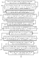
Please refer to FIG. 1. FIG. 1 is a block diagram illustrating a prior art video stream processing apparatus 10 for video conversion. As shown in FIG. 1, the video stream processing apparatus 10 includes a data buffering system 100 and a frame rate converter 102. The data buffering system 100 receives a video stream with a plurality of frames and stores them into a storage 130. Then, a first traffic controller 110 accesses a first frame and a second frame from the storage 130 and buffers them in a first buffer 112 and a second buffer 114, respectively. When the video stream is displayed, a frame rate converter 102 accesses the first frame and the second frame from the first buffer 112 and the second buffer 114, respectively, and interpolates a first interpolated frame. Continuously, after the first interpolated frame is generated, the frame rate converter 102 outputs the first interpolated frame. As a result, the video conversion of the prior art architecture only interpolates one interpolated frame.
However, when the frame rate up-conversion is performed, more particularly in a film mode, the conventional frame rate converter only duplicates the generated frame according to the approach of generating frames with prior art video processors. The above-mentioned approach may increase the LCD's response time and reduce performance.
Therefore, a novel method of frame interpolation for frame rate up-conversion is required to both improve the motion blur and flicker issues and to shorten the LCD's response time.
SUMMARY OF THE INVENTION
It is therefore one of the objectives of the claimed invention to provide a method for video conversion of a video stream and apparatus thereof, to solve the above-mentioned problems and enhance image quality.
According to one embodiment of the claimed invention, a method for video conversion of a video stream comprises: interpolating a first interpolated frame according a first frame and a second frame of the video stream; and interpolating a second interpolated frame according to the first frame and the first interpolated frame
According to yet another embodiment of the present invention, an apparatus for video conversion of a video stream is provided. The apparatus comprises: a data buffering system, for storing the video stream including a first frame and a second frame; and a frame rate converter, coupled to the data buffering system, for interpolating a first interpolated frame according to the first frame and the second frame and for interpolating a second interpolated frame according to the first frame and the first interpolated frame.
These and other objectives of the present invention will no doubt become obvious to those of ordinary skill in the art after reading the following detailed description of the preferred embodiment that is illustrated in the various figures and drawings.
BRIEF DESCRIPTION OF THE DRAWINGS
FIG. 1 is a block diagram of a prior art video stream processing apparatus.
FIG. 2 is a block diagram illustrating an apparatus for video conversion of a video stream according to an embodiment of the present invention.
FIG. 3 is a flowchart illustrating a method for video conversion of a video stream according to one embodiment of the present invention.
FIG. 4 is a diagram illustrating an exemplary video conversion of a video stream.
FIG. 5 is a continued diagram of the exemplary video conversion shown in FIG. 4.
FIG. 6 is a continued diagram of the exemplary video conversion shown in FIG. 5.
FIG. 7 is a continued diagram of the exemplary video conversion shown in FIG. 6.
FIG. 8 is a sequence diagram illustrating video conversion of the video stream.
DETAILED DESCRIPTION
Certain terms are used throughout the following description and claims to refer to particular system components. As one skilled in the art will appreciate, manufacturers may refer to a component by different names. This document does not intend to distinguish between components that differ in name but not function. In the following discussion and in the claims, the terms “including” and “comprising” are used in an open-ended fashion, and thus should be interpreted to mean “including, but not limited to . . . .” The terms “couple” and “couples” are intended to mean either an indirect or a direct electrical connection. Thus, if a first device couples to a second device, that connection may be through a direct electrical connection, or through an indirect electrical connection via other devices and connections.
Please refer to FIG. 2. FIG. 2 is a diagram illustrating an apparatus 20 for video conversion of a video stream according to an embodiment of the present invention. The apparatus 20 comprises a data buffering system 200, for storing the video stream including at least a first frame and a second frame; and a frame rate converter 202, coupled to the data buffering system 200, for interpolating a first interpolated frame according to the first frame and the second frame and for interpolating a second interpolated frame according to the first frame and the first interpolated frame. In addition, the frame rate converter 202 further interpolates a third interpolated frame according to the second frame and the first interpolated frame. The data buffering system 200 comprises a storage 230, for storing the video stream; a first traffic controller 210, coupled to the storage 230 and the frame rate controller 202, for controlling data transfer between the storage 230 and the frame rate controller 202; and a second traffic controller 220, coupled to the storage 230 and the frame rate controller 202, for controlling data transfer between the storage 230 and the frame rate controller 202. In this embodiment, the first traffic controller 210 includes: a first buffer 212, storing the first frame; a second buffer 214, storing the second frame; and a third buffer 216; and the second traffic controller 220 includes a fourth buffer 222. Accordingly, after the first interpolated frame is generated, the frame rate controller 202 outputs the first frame and buffers the first interpolated frame into the fourth buffer 222 of the second traffic controller 220; and then the first interpolated frame buffered in the fourth buffer 222 is further buffered into the third buffer 216 of the first traffic controller 210; and after the first frame is outputted and the second interpolated frame is generated, the first traffic controller 210 overwrites the first frame buffered in the first buffer 212 by a third frame immediately following the second frame in the video stream. Furthermore, the frame rate converter 202 further sequentially outputs the second interpolated frame and the first interpolated frame after the first frame is outputted; and after the first interpolated frame is outputted, the first traffic controller 210 further overwrites the first interpolated frame buffered in the third buffer 216 by the third interpolated frame. And then, the frame rate converter 202 further interpolates a fourth interpolated frame according to the second frame buffered in the second buffer 214 and the third frame buffered in the first buffer 212, and then outputs the third interpolated frame buffered in the third buffer 216. After the third interpolated frame is outputted, the first traffic controller 210 further overwrites the third interpolated frame buffered in the third buffer 216 by the fourth interpolated frame. Please note that architectures and principles of the aforementioned circuit elements 200, 202, 210, 212, 214, 216, 220, 222 and 230 are well known in the art, and therefore not explained in detail herein for the sake of brevity.
Please note that in above exemplary embodiment, the second frame immediately follows the first frame in the video stream, and the third frame immediately follows the second frame in the video stream. Additionally, the aforementioned video stream is a 2:2 pull-down video stream. However, these are for illustrative purposes only and are not meant to be limitations of the present invention. That is, without departing from the spirit of the present invention, other alternative embodiments are available.
Please refer to FIG. 2 in conjunction with FIG. 3. FIG. 3 is a flowchart illustrating a method for video conversion of a video stream according to one embodiment of the present invention. Provided that the result is substantially the same, the steps are not limited to be executed according to the exact order shown in FIG. 3. Referring to the flowchart, the operations for video conversion of the video stream are described as follows:
In Step 300, the data buffering system 200 receives the video stream sequentially or randomly, where the video stream comprises, without limitation, the first frame A, the second frame B and the third frame C, and stores the first frame A and the second frame B of the video stream into the storage 230. Then, in Step 302, when the first frame A and the second frame B of the video stream are displayed, the first traffic controller 210 accesses the first frame A and the second frame B of the video stream from the storage 203 and buffers the first frame A of the video stream and the second frame B of the video stream into the first buffer 212 and the second buffer 214, respectively, of the first traffic controller 210. In Step 304, the frame rate converter 202 accesses the first frame A of the video stream as the signal S1 and accesses the second frame B of the video stream as the signal S2 from the first buffer 212 and the second buffer 214, respectively, of the first traffic controller 210 in the data buffering system 200. Next, in Step 306, the frame rate converter 202 interpolates the first interpolated frame A″ according to the first frame A (e.g. the signal S1 in FIG. 2) of the video stream and the second frame B (e.g. the signal S2 in FIG. 2) of the video stream, and buffers the first interpolated frame A″ into the fourth buffer 222 of the second traffic controller 220, as indicated by the signal S4 in FIG. 2. The frame rate converter 202 synchronously outputs the first frame A, as indicated by the signal S5 in FIG. 2. It should be noted that the aforementioned frame buffering operation and frame outputting operation are not limited to be synchronous. In other embodiments of the present invention, without departing from the spirit of the present invention, performing the frame buffering operation and frame outputting operation asynchronously is also possible.
It should be noted that a skilled person can also readily appreciate the operations of the aforementioned operations of Step 300 to 306 in FIG. 3 after reading the above disclosure in conjunction with FIG. 2 and FIG. 4.
Continuing in Step 308, the second traffic controller 220 stores the first interpolated frame A″ into the storage 230 when the first interpolated frame A″ is needed for following frame interpolation operation. In Step 310, the first traffic controller 210 accesses the first interpolated frame A″ from the storage 230 and buffers it into the third buffer 216. Next, in Step 312, the frame rate converter 202 accesses the first frame A buffered in the first buffer 212 as the signal S1, and the first interpolated frame A″ buffered in the third buffer 214 as the signal S3 from the first traffic controller 210. The frame rate converter 202 then interpolates the second interpolated frame A′ according to the first frame A (e.g., signal S1) and the first interpolated frame A″ (e.g., signal S3). In Step 314, the frame rate converter 202 buffers the first interpolated frame A″ as indicated by the signal S4 into the fourth buffer 222 of the second traffic controller 220, and synchronously outputs the second interpolated frame A′ as indicated by the signal S5. It should be noted that the aforementioned frame buffering operation and frame outputting operation are not limited to be synchronous. In other embodiments of the present invention, without departing from the spirit of the present invention, performing the frame buffering operation and frame outputting operation asynchronously is also possible.
It should be noted that, at this time, the first traffic controller 210 accesses the third frame C from the storage 230 and buffers it into the first buffer 212. Accordingly, the third frame C overwrites the first frame A stored in the first buffer 212 because the first frame A is no longer needed in the following frame interpolation operation and has been outputted for display.
A skilled person can readily appreciate the operations of the aforementioned operations of Step 308 to 314 in FIG. 3 after reading the above disclosure while referring to FIG. 2 and FIG. 5.
Continuing onto Step 316, the frame rate converter 202 accesses the second frame B as the signal S2 and the first interpolated frame A″ as the signal S3 from the second buffer 214 and the third buffer 216 of the first traffic controller 210, respectively, and then interpolates the third interpolated frame A′″ according to the second frame B (e.g., the signal S2) and the first interpolated frame A″ (e.g., the signal S3). Next, in Step 318, the frame rate converter 202 buffers the third interpolated frame A′″ as the signal S4 into the fourth buffer 222 of the second traffic controller 220 and synchronously outputs the first interpolated frame A″ as the signal S5. It should be noted that the aforementioned frame buffering operation and frame outputting operation are not limited to be synchronous. In other embodiments of the present invention, without departing from the spirit of the present invention, performing the frame buffering and outputting operations asynchronously is also possible.
At this time, the second traffic controller 220 stores the third interpolated frame A′″ into the storage 230, then the first traffic controller 210 accesses the third interpolated frame A′″ from the storage 230 and buffers it into the third buffer 216. Accordingly, the third interpolated frame A′″ overwrites the first interpolated frame A″ in the third buffer 216 because the first interpolated frame A″ is no longer needed in the following frame interpolation operation and has been outputted for display.
A skilled person can readily appreciate the operations of the aforementioned operations of Step 316 to 320 in FIG. 3 after reading the above disclosure in conjunction with FIG. 2 and FIG. 6.
Further on in Step 320, the frame rate converter 202 accesses the second frame B as the signal S2 and the third frame C as the signal S1 from the second buffer 214 and the first buffer 212 of the first traffic controller 210, respectively, and then interpolates the fourth interpolated frame B′″ according to the second frame B (e.g., the signal S2) and the third frame C (e.g., the signal S1). Next, in Step 322, the frame rate converter 202 buffers the fourth interpolated frame B″ as the signal S4 into the fourth buffer 222 of the second traffic controller 220 and synchronously outputs the third interpolated frame A′″ as the signal S5. It should be noted that the aforementioned frame buffering operation and frame outputting operation are not limited to be synchronous. In other embodiments of the present invention, without departing from the spirit of the present invention, performing the buffering and outputting operations asynchronously is also possible.
Then the second traffic controller 220 stores the fourth interpolated frame B″ into the storage 230, then the first traffic controller 210 accesses the fourth interpolated frame B′″ from the storage 230 and buffers it into the third buffer 216. Accordingly, the fourth interpolated frame B″ overwrites the third interpolated frame (A′″) stored in the third buffer 216 because the third interpolated frame A′″ is no longer needed in the following frame interpolation operation and has been outputted for display.
A skilled person can readily appreciate the operations of the aforementioned operations of Step 320 to 322 in FIG. 3 after reading the above disclosure in conjunction with FIG. 2 and FIG. 7.
Please refer to FIG. 8. FIG. 8 is a sequence diagram illustrating video conversion of the video stream. Referring to the above disclosure, an ordinary person skilled in the art can readily appreciate operations of the frame interpolation of the video stream as illustrated in FIG. 8. Further description of the frame interpolations is omitted here for the sake of brevity.
The illustrations of the aforementioned embodiments perform three counts of interpolation between two frames to obtain three interpolated frames for advancing the sharpness of the video, and more particularly, the sharpness of edges of the video. In the aforementioned embodiments, the order of the interpolation is as follows: first, the frame A″ is interpolated according to the first frame A and the second frame B, i.e. the frame A″ corresponds to the aforementioned first interpolated frame; then, the frame A′ is interpolated according to the first frame A and the frame A″, i.e. frame A′ corresponds to the aforementioned second interpolated frame; lastly, the frame A′″ is interpolated according to the frame A″ and the second frame B, i.e. the frame A′″ corresponds to the aforementioned third interpolated frame. Additionally, in the present invention, the frame A″ is first interpolated according to the first frame A and the second frame B, i.e. the frame A″ is corresponding to the aforementioned first interpolated frame; then, frame A′″ is interpolated according to the first frame A and the frame A″, i.e. the frame A′″ corresponds to the aforementioned second interpolated frame; finally, the frame A′ is interpolated according to the frame A″ and the second frame B, i.e. frame A′ corresponds to the aforementioned third interpolated frame. Please note that the aforementioned interpolated order is for illustrative purposes only and is not meant to be a limitation of the present invention.
According to another alternative design of the present invention, the video conversion performs two counts of interpolation between the two original frames. As a result, the alternative design of the present invention also enhances the sharpness of the video over the prior art, and is more efficient than the prior art.
In conclusion, the video stream of a film mode displayed in current media display system is smoother and clearer due to the disclosed frame interpolation scheme. In addition, the data buffering system of the present invention has an additional traffic controller having a cheap buffer included therein, and is implemented without substantially altering the conventional hardware architecture. In other words, the hardware implementation is not complicated, and the production cost remains low.
Those skilled in the art will readily observe that numerous modifications and alterations of the device and method may be made while retaining the teachings of the invention.

Claims (8)

1. A method for video conversion of a video stream, the method being applied to an apparatus for video conversion of the video stream, the method comprising:
interpolating according to a frame FA and a frame FB of the video stream to generate a frame FA″, wherein the frame FB follows the frame FA in the video stream;
interpolating according to the frame FA and the frame FA″ generate a frame FA′;
interpolating according to the frame FB and the frame FA″ to generate a frame FA′″;
buffering the frame FA and the frame FB;
after the frame FA″ is generated, outputting the frame FA and buffering the frame FA″; and
after the frame FA is outputted and the frame FA′ is generated, overwriting the frame FA by a frame FC following the frame FB in the video stream.
2. The method of claim 1, further comprising:
sequentially outputting the frame FA′ and the frame FA″ after the first frame FA is outputted; and
after the frame FA″ is outputted, overwriting the frame FA″ by the frame FA′″.
3. The method of claim 2, further comprising:
interpolating according to the frame FB and the frame FC to generate a frame FB′″;
outputting the frame FA′″; and
after the frame FA′″ is outputted, overwriting the frame FA′″ by the frame FB′″.
4. The method of claim 1, wherein the video stream is a 2:2 pull-down video stream.
5. An apparatus for video conversion of a video stream, comprising:
a data buffering system, for storing the video stream including a frame FA and a frame FB; and
a frame rate converter, coupled to the data buffering system,
for interpolating according to the frame FA and the frame FB to generate a frame FA″ and for interpolating according to the frame FA and the frame FA″ to generate a frame FA′, and for interpolating according to the frame FB and the frame FA″ to generate a frame FA′″, wherein the frame FB follows the frame FA in the video stream;
wherein the data buffering system comprises:
a storage, for storing the video stream;
a first traffic controller, coupled to the storage and the frame rate controller, for controlling data transfer between the storage and the frame rate controller, the first traffic controller comprising:
a first buffer, storing the frame FA;
a second buffer, storing the frame FB; and
a third buffer; and
a second traffic controller, coupled to the storage and the frame rate controller, for controlling data transfer between the storage and the frame rate controller, the second traffic controller comprising a fourth buffer;
wherein after the frame FA″ is generated, the frame rate controller outputs the frame FA and stores the frame FA″ into the fourth buffer of the second traffic controller; and then the frame FA″ buffered in the fourth buffer is further buffered into the third buffer of the first traffic controller; and after the frame FA is outputted and the frame FA′ is generated, the first traffic controller overwrites the first frame FA buffered in the first buffer by a frame Fc following the frame FB in the video stream.
6. The apparatus of claim 5, wherein the frame rate converter further sequentially outputs the frame FA′ and the frame FA″ after the frame FA is outputted; and after the frame FA″ is outputted, the first traffic controller further overwrites the frame FA″ buffered in the third buffer by the frame FA′″.
7. The apparatus of claim 6, wherein the frame rate converter further interpolates according to the frame FB buffered in the second buffer and the frame FC buffered in the first buffer to generate a frame FB′″; the frame rate converter outputs the frame FA′″ buffered in the third buffer; and after the frame FA′″ is outputted, the first traffic controller further overwrites the frame FA′″ buffered in the third buffer by the frame FB′″.
8. The apparatus of claim 5, wherein the video stream is a 2:2 pull-down video stream.
US11/855,160 2007-09-14 2007-09-14 Method for video conversion of video stream and apparatus thereof Active 2030-12-22 US8237859B2 (en)

Priority Applications (3)

Application Number Priority Date Filing Date Title
US11/855,160 US8237859B2 (en) 2007-09-14 2007-09-14 Method for video conversion of video stream and apparatus thereof
TW097108846A TWI384880B (en) 2007-09-14 2008-03-13 Method for video conversion of video stream and apparatus thereof
CN2008100948013A CN101388189B (en) 2007-09-14 2008-04-28 Method for video conversion of video stream and apparatus thereof

Applications Claiming Priority (1)

Application Number Priority Date Filing Date Title
US11/855,160 US8237859B2 (en) 2007-09-14 2007-09-14 Method for video conversion of video stream and apparatus thereof

Publications (2)

Publication Number Publication Date
US20090073312A1 US20090073312A1 (en) 2009-03-19
US8237859B2 true US8237859B2 (en) 2012-08-07

Family

ID=40454023

Family Applications (1)

Application Number Title Priority Date Filing Date
US11/855,160 Active 2030-12-22 US8237859B2 (en) 2007-09-14 2007-09-14 Method for video conversion of video stream and apparatus thereof

Country Status (3)

Country Link
US (1) US8237859B2 (en)
CN (1) CN101388189B (en)
TW (1) TWI384880B (en)

Cited By (1)

* Cited by examiner, † Cited by third party
Publication number Priority date Publication date Assignee Title
US11871146B1 (en) * 2022-08-16 2024-01-09 Novatek Microelectronics Corp. Video processor for handling irregular input

Families Citing this family (1)

* Cited by examiner, † Cited by third party
Publication number Priority date Publication date Assignee Title
KR102272132B1 (en) * 2014-12-26 2021-07-01 삼성전자주식회사 Semiconductor device and method for operating the same

Citations (10)

* Cited by examiner, † Cited by third party
Publication number Priority date Publication date Assignee Title
US6549240B1 (en) 1997-09-26 2003-04-15 Sarnoff Corporation Format and frame rate conversion for display of 24Hz source video
TW540241B (en) 2001-11-15 2003-07-01 Chi Mei Optoelectronics Corp Display method for stablizing MPEG video output via an LCD device
US20040071313A1 (en) * 2002-08-07 2004-04-15 Marko Hahn Apparatus and method for motion-vector-aided interpolation of a pixel of an intermediate image of an image sequence
US6930728B2 (en) * 2000-06-22 2005-08-16 Lg Electronics Inc. Scan conversion apparatus
US6975359B2 (en) * 2002-04-25 2005-12-13 Trident Microsystems, Inc. Method and system for motion and edge-adaptive signal frame rate up-conversion
US20050285815A1 (en) 2004-06-14 2005-12-29 Genesis Microchip Inc. LCD blur reduction through frame rate control
US20060092321A1 (en) 2004-10-29 2006-05-04 Masahiro Ogino Image interpolation device and a frame rate converter and image display apparatus using the same
US7295245B2 (en) * 2003-10-14 2007-11-13 Samsung Electronics Co., Ltd. Method and apparatus for converting frame rate using time shifting and motion compensation
US7375763B2 (en) * 2003-08-26 2008-05-20 Stmicroelectronics S.R.L. Method and system for de-interlacing digital images, and computer program product therefor
US7843509B2 (en) * 2005-09-29 2010-11-30 Trident Microsystems (Far East) Ltd. Iterative method of interpolating image information values

Patent Citations (10)

* Cited by examiner, † Cited by third party
Publication number Priority date Publication date Assignee Title
US6549240B1 (en) 1997-09-26 2003-04-15 Sarnoff Corporation Format and frame rate conversion for display of 24Hz source video
US6930728B2 (en) * 2000-06-22 2005-08-16 Lg Electronics Inc. Scan conversion apparatus
TW540241B (en) 2001-11-15 2003-07-01 Chi Mei Optoelectronics Corp Display method for stablizing MPEG video output via an LCD device
US6975359B2 (en) * 2002-04-25 2005-12-13 Trident Microsystems, Inc. Method and system for motion and edge-adaptive signal frame rate up-conversion
US20040071313A1 (en) * 2002-08-07 2004-04-15 Marko Hahn Apparatus and method for motion-vector-aided interpolation of a pixel of an intermediate image of an image sequence
US7375763B2 (en) * 2003-08-26 2008-05-20 Stmicroelectronics S.R.L. Method and system for de-interlacing digital images, and computer program product therefor
US7295245B2 (en) * 2003-10-14 2007-11-13 Samsung Electronics Co., Ltd. Method and apparatus for converting frame rate using time shifting and motion compensation
US20050285815A1 (en) 2004-06-14 2005-12-29 Genesis Microchip Inc. LCD blur reduction through frame rate control
US20060092321A1 (en) 2004-10-29 2006-05-04 Masahiro Ogino Image interpolation device and a frame rate converter and image display apparatus using the same
US7843509B2 (en) * 2005-09-29 2010-11-30 Trident Microsystems (Far East) Ltd. Iterative method of interpolating image information values

Cited By (1)

* Cited by examiner, † Cited by third party
Publication number Priority date Publication date Assignee Title
US11871146B1 (en) * 2022-08-16 2024-01-09 Novatek Microelectronics Corp. Video processor for handling irregular input

Also Published As

Publication number Publication date
TW200913715A (en) 2009-03-16
TWI384880B (en) 2013-02-01
CN101388189B (en) 2011-06-01
CN101388189A (en) 2009-03-18
US20090073312A1 (en) 2009-03-19

Similar Documents

Publication Publication Date Title
TWI408634B (en) Dynamically selecting either frame rate conversion (frc) or pixel overdrive in an lcd panel based display
US8063861B2 (en) Image display unit
KR100806858B1 (en) High definition image dislpay device and method for frame rate conversion thereof
WO2006019867A2 (en) A dual-scaler architecture for reducing video processing requirements
JP5317825B2 (en) Image processing apparatus and image processing method
JP4367100B2 (en) Image display device
JP5051983B2 (en) LCD blur reduction by frame rate control
CN111510773A (en) Resolution adjustment method, display screen, computer storage medium and equipment
US20130176485A1 (en) Video control device and video control method
JP2005017484A (en) Unit, method, and program for image display
US8237859B2 (en) Method for video conversion of video stream and apparatus thereof
TWI411308B (en) Video processing method and related video processing apparatus thereof
EP2669886A1 (en) Image processing method and image display system utilizing the same
TW201016002A (en) System and method for processing multi-interface image signals
JP2008040384A (en) Video signal processing system and display apparatus using the same
JP2007010699A (en) Liquid crystal display device
US7903175B2 (en) Device and method for zooming images
US20090214136A1 (en) Image processing apparatus for scaling an input image according to various image processing requirements and method thereof
CN114727051B (en) Media resource transmission device, system and method
US8300146B2 (en) Display frequency boosting system for increasing image display frequency
JP4556198B2 (en) Image display device
WO2021042661A1 (en) Display device and image output method
JP3863887B2 (en) Display drive device
US20100020236A1 (en) Image display apparatus and method
US20110292292A1 (en) Method and apparatus for displaying video data

Legal Events

Date Code Title Description
AS Assignment

Owner name: HIMAX TECHNOLOGIES LIMITED, TAIWAN

Free format text: ASSIGNMENT OF ASSIGNORS INTEREST;ASSIGNOR:LU, YI-PIN;REEL/FRAME:019826/0328

Effective date: 20070820

STCF Information on status: patent grant

Free format text: PATENTED CASE

FPAY Fee payment

Year of fee payment: 4

MAFP Maintenance fee payment

Free format text: PAYMENT OF MAINTENANCE FEE, 8TH YEAR, LARGE ENTITY (ORIGINAL EVENT CODE: M1552); ENTITY STATUS OF PATENT OWNER: LARGE ENTITY

Year of fee payment: 8

FEPP Fee payment procedure

Free format text: MAINTENANCE FEE REMINDER MAILED (ORIGINAL EVENT CODE: REM.); ENTITY STATUS OF PATENT OWNER: LARGE ENTITY