US8180048B2 - Method and system for computational transformation - Google Patents
Method and system for computational transformation Download PDFInfo
- Publication number
- US8180048B2 US8180048B2 US11/572,635 US57263507A US8180048B2 US 8180048 B2 US8180048 B2 US 8180048B2 US 57263507 A US57263507 A US 57263507A US 8180048 B2 US8180048 B2 US 8180048B2
- Authority
- US
- United States
- Prior art keywords
- data
- bits
- keyset
- input
- transformation
- Prior art date
- Legal status (The legal status is an assumption and is not a legal conclusion. Google has not performed a legal analysis and makes no representation as to the accuracy of the status listed.)
- Expired - Fee Related, expires
Links
Images
Classifications
-
- H—ELECTRICITY
- H04—ELECTRIC COMMUNICATION TECHNIQUE
- H04L—TRANSMISSION OF DIGITAL INFORMATION, e.g. TELEGRAPHIC COMMUNICATION
- H04L9/00—Cryptographic mechanisms or cryptographic arrangements for secret or secure communications; Network security protocols
- H04L9/06—Cryptographic mechanisms or cryptographic arrangements for secret or secure communications; Network security protocols the encryption apparatus using shift registers or memories for block-wise or stream coding, e.g. DES systems or RC4; Hash functions; Pseudorandom sequence generators
- H04L9/0618—Block ciphers, i.e. encrypting groups of characters of a plain text message using fixed encryption transformation
-
- H—ELECTRICITY
- H04—ELECTRIC COMMUNICATION TECHNIQUE
- H04L—TRANSMISSION OF DIGITAL INFORMATION, e.g. TELEGRAPHIC COMMUNICATION
- H04L9/00—Cryptographic mechanisms or cryptographic arrangements for secret or secure communications; Network security protocols
- H04L9/06—Cryptographic mechanisms or cryptographic arrangements for secret or secure communications; Network security protocols the encryption apparatus using shift registers or memories for block-wise or stream coding, e.g. DES systems or RC4; Hash functions; Pseudorandom sequence generators
- H04L9/0643—Hash functions, e.g. MD5, SHA, HMAC or f9 MAC
-
- H—ELECTRICITY
- H04—ELECTRIC COMMUNICATION TECHNIQUE
- H04L—TRANSMISSION OF DIGITAL INFORMATION, e.g. TELEGRAPHIC COMMUNICATION
- H04L9/00—Cryptographic mechanisms or cryptographic arrangements for secret or secure communications; Network security protocols
- H04L9/06—Cryptographic mechanisms or cryptographic arrangements for secret or secure communications; Network security protocols the encryption apparatus using shift registers or memories for block-wise or stream coding, e.g. DES systems or RC4; Hash functions; Pseudorandom sequence generators
- H04L9/065—Encryption by serially and continuously modifying data stream elements, e.g. stream cipher systems, RC4, SEAL or A5/3
- H04L9/0656—Pseudorandom key sequence combined element-for-element with data sequence, e.g. one-time-pad [OTP] or Vernam's cipher
- H04L9/0662—Pseudorandom key sequence combined element-for-element with data sequence, e.g. one-time-pad [OTP] or Vernam's cipher with particular pseudorandom sequence generator
-
- H—ELECTRICITY
- H04—ELECTRIC COMMUNICATION TECHNIQUE
- H04L—TRANSMISSION OF DIGITAL INFORMATION, e.g. TELEGRAPHIC COMMUNICATION
- H04L2209/00—Additional information or applications relating to cryptographic mechanisms or cryptographic arrangements for secret or secure communication H04L9/00
- H04L2209/24—Key scheduling, i.e. generating round keys or sub-keys for block encryption
Definitions
- the invention relates generally to the field of cryptography.
- the invention relates to a method and system for symmetric encryption and decryption, random number generation and hash code generators using a true one-way function.
- the present invention pertains to cryptographic communications and methods, to provide secure communication over a communications channel and to store data securely on a computing system.
- Symmetric encryption uses algorithms where the same keyset is used for both the encryption as well as the decryption process.
- the key generated must be kept secret, and is shared by the message sender and recipient.
- a password used in a Microsoft Word document uses symmetric encryption techniques where the password used to encrypt and decrypt the file is the same and is used to secure the file from eves droppers.
- the person encrypting the file with a password must inform the receiver of the password, either physically or through any other means, in order for the receiver to be able to decrypt the file.
- Symmetric key encryptions can be divided into stream ciphers and block ciphers.
- Stream ciphers encrypt the bits of the message one at a time, and block ciphers take a number of bits and encrypt them as a single unit. Typically, blocks of 64 bits are used.
- Symmetric-key algorithms are generally much faster to execute than asymmetric encryption algorithms.
- symmetric-key algorithms do have certain pitfalls. One being the requirement of a shared secret key with one copy at the sender and receivers end. Since keys are subject to discovery by a cryptographic adversary, they need to be changed often and kept secure during distribution and service. An alternative to this is the use of asymmetric encryption to encrypt data or to transfer the password and then carry out symmetric encryption.
- One of the first cryptographic communications method to be used were the data encryption standards tools adopted by the National Bureau of Standards, Federal Register, Mar. 17, 1975, Volume 40, No. 52 and Aug. 1, 1975, Vol. 40, No. 149.
- a cryptographic communications channel normally comprises of an encryption system and a decryption system coupled to the communications channel.
- the message is encrypted using the encryption system at one end of the communications channel and sending it across the communication channel where it is decoded by the decryption channel at the other end of the channel.
- the message is defined to be a digital message represented by numerical characters, these characters, generally being the Binary notation characters of 0 and 1.
- the cryptographic systems in use essentially highlight the use of an encoding key or operator, K, on the digital message that is to be encoded, M, and encode the message M onto the encoded version E, where, K and E are also digital sequences of numerical characters, represented in the same notation as M.
- the encrypting device takes as input, M and K, and then operates on M using K and encrypts it into E.
- the decrypting device takes E and the decrypting key or operator K′ as the input, operates on E using K′ and decrypt it into the deciphered text M′.
- K′ and M′ are also digital sequences of numerical characters, represented in the same notation as M.
- the public key (KP) is available on the public file system of the user, whereas the private key (KPr) remains with the user.
- KP public key
- KPr private key
- a user B has to send an encrypted message to user A
- the message M is encrypted using the public key of user A.
- User A then decrypts the encrypted message using the private key which is known only to user A.
- This method is further employed to act as the authorization on electronic signatures.
- it is absolutely essential to make a judicious selection of the private key as this selection would determine the vulnerability of the encrypted message to eavesdroppers.
- the selected key should be computationally difficult to compute.
- the RSA patent U.S. Pat. No. 4,405,829, has employed a scheme to generate the private key for the user based on prime number factorization to make the computation of the private key by eavesdroppers computationally much difficult (computationally expensive process).
- the RSA method of encrypting and decrypting employs the same public and private key concepts as mentioned in the Diffie and Hellman system to encrypt and decrypt a message.
- the keyset required to encipher it should be unique for every message and the length of the keyset should be greater than or equal to the length of the message to be communicated. No method of encrypted communication can be totally secure until it employs the above-mentioned scheme.
- the proposed system and method hopes to overcome all the shortcomings of the existing technologies to provide a full-proof unbreakable symmetric key encryption.
- the system and method is also used to address the needs for generating random numbers and unique hash codes.
- FIG. 1 shows a block diagram of a communications channel
- FIG. 2 shows a block diagram of the architecture of the system pursuant to an embodiment of the invention.
- FIG. 3 shows a block diagram of an embodiment of the structure of a keyset.
- FIG. 4 shows a flow diagram of the steps performed during forward transformation pursuant to an embodiment of the invention.
- FIG. 5 shows a block diagram of the stages of forward transformations performed on the keyset and the process of transforming the input-data to output-data pursuant to an embodiment of the invention.
- FIG. 6 shows a flow diagram of the steps performed during reverse transformation pursuant to an embodiment of the invention.
- FIG. 7 shows a block diagram of the stages of reverse transformations performed on the keyset and the process of transforming the output-data to input-data pursuant to an embodiment of the invention.
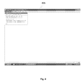
- FIG. 8 shows a screenshot of the initiation of the computational transformation process module during the forward transformation process according to one embodiment of the invention.
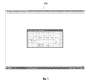
- FIG. 9 shows a screenshot of the initial conditions of the computational transformation process module during the forward transformation process according to one embodiment of the invention.
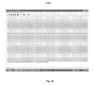
- FIG. 10 shows a screenshot of the contents of the input-data into the computational transformation process module during the forward transformation process according to one embodiment of the invention
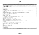
- FIG. 11 shows a screenshot of the contents of output-data from the computational transformation process module during the forward transformation process according to one embodiment of the invention.
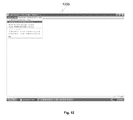
- FIG. 12 shows a screenshot of the initiation of the computational transformation process module during the reverse transformation process according to one embodiment of the invention.
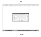
- FIG. 13 shows a screenshot of the initial conditions of the computational transformation process module during the reverse transformation process according to one embodiment of the invention.
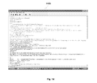
- FIG. 14 shows a screenshot of the contents of the output-data into the computational transformation process module during the reverse transformation process according to one embodiment of the invention.
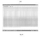
- FIG. 15 shows a screenshot of the contents of input-data from the computational transformation process module during the reverse transformation process according to one embodiment of the invention.
- One of the embodiments of the forward transformation and reverse transformation is the process of encryption and decryption respectively.
- Encryption and decryption is an inevitable process for transmitting data securely over a communications channel and also used to store data or information securely on a computing system.
- Several existing technologies for encryption and decryption have been described in the background of the invention. However, the current invention addresses and overcomes the core problem in earlier and current encryption mechanisms and technologies.
- the present invention makes use of a true one-way process for forward transformation as well as reverse transformation i.e. to encrypt as well as decrypt data in an embodiment of the invention.
- the present invention's core functionality is explained as below:
- the same function ‘f’ is used in the process of forward transformation as well as reverse transformation, and the keyset used is same in both the cases and only change is the change in the indicator value, where the indicator represents the kind of transformation to be carried out.
- the function ‘f’ is proceeding in one direction only, that is, from k to k′ i.e. primary keyset (k) to secondary keyset (k′).
- the transformation of k to k′ is true one-way process, is same in the forward transformation as well as the reverse transformation.
- FIG. 1 shows a communications channel 110 and two computing terminals 105 and 115 coupled to the channel.
- the communications channel may include, for example, a wide area network such as the Internet, a local area network, or a wireless network including base and mobile stations.
- the computing terminals may comprise, for example, a computer or a hand held device, such as a mobile phone or a personal digital assistant (PDA).
- PDA personal digital assistant
- the technology implemented in the invention can be used to send data securely over a communications channel by using any of the devices listed above.
- FIG. 2 shows the architecture of the invention on computing terminal 205 .
- the invention can be used to send data securely over a communications channel as well as to store data securely on a standalone computer.
- Each computing terminal comprises a processor readable or a short term memory 210 , a processor 215 , a long-term memory 220 and a transceiver, each one in communication with the other.
- the computational transformation module 225 is stored in the long-term memory 220 of the computing terminal 205 .
- the transceiver is used to transmit and receive data from one computing terminal to the other. Data created by any application, for example, a word file or an excel spreadsheet or any data from other applications, is taken in the form of an ‘n’ bit block of input-data in this embodiment.
- the computational transformation module 225 is responsible for converting the input-data into an output-data in this embodiment of the invention.
- An output-data is the output received when the input-data is passed through the computational transformation module 225 .
- the output-data is a form of input-data that has been encrypted by performing the forward transformation onto the input-data data into seemingly meaningless data.
- this encrypted data can also be stored on the computing terminal 205 to protect data from any misuse or to maintain user privacy.
- the encrypted data can be sent to another computing terminal. It is sent in an encrypted form to prevent eavesdroppers or other third parties from getting access to the original data.
- the output-data can be performed upon the process of reverse transformation i.e.
- the embodiment of the invention as a process of encryption and decryption is a symmetric process and if used to send data securely over a communications network 110 , the same keyset needs to be present at the sending computer 105 to encrypt the data and the receiving computer 115 to decrypt the data.
- the computational transformation module 225 includes a keyset that is used to encrypt the blocks of input-data.
- the present invention is an ‘n’ bit block transformation method, where ‘n’ is atleast of a length, one bit. As the size ‘n’ increases, the computing resources such as memory and processor speed that would be required would be more and hence slow down the transformation process. In present day systems, the ideal size for ‘n’ would be 8 bits.
- the present invention is capable of transforming each bit of input-data using a different unique keyset. Alternatively, it is also able to encrypt a predetermined number of bits i.e. a block at a time.
- the input block of the input-data is referred as ‘n’ bit block and the output block of the output-data is referred as ‘m’ bit block.
- the input-data can be converted into ‘n’ bit blocks of 3 bits and each ‘n’ bit block can be encrypted using a unique keyset to obtain the ‘m’ bit block of output-data.
- the design of the keyset is based on the size of ‘n’ bit block of input-data used for encrypting the input-data.
- FIG. 3 shows one embodiment of the keyset where the keyset is a two-dimensional array with two columns and the number of rows is equal to 2 n where ‘n’ represents size in number of bits of input block of the input-data, that is referred as ‘n’ bit block. As shown in the FIG.
- the row numbers of the two dimensional array starts from 0 to (2 n ⁇ 1). For example, as shown in FIG. 3 , to encrypt a block of 3 bits there would be 2 3 rows i.e. 8 rows.
- the first column 305 of the two dimensional array will comprise of unique ‘n’ bit numbers and is referred to as the Reference column 1 (“Ref 1 ”). Since the keyset shown in the FIG. 3 is used to encrypt a block of 3 bits of input-data, the Ref 1 contains the numbers from zero to seven in any order.
- the second column 310 of the two dimensional array comprises of random numbers and is referred to as the Energy-Value column (“E-Val”).
- the random numbers can be of any predetermined size of ‘v’ bits, where ‘v’ represents the size of the E-Val column in bits.
- the E-Val column of the keyset is then sorted using any sort algorithm. In one embodiment, the numbers in the second column 310 are sorted in a descending or ascending order or any predefined order.
- the row numbers of the array being unique and in order i.e. zero to seven, is used as another hidden Reference column in the process of transformation. This structure represents one embodiment of the structure of the keyset.
- a two dimensional array with three columns and 2n rows where ‘n’ represents the size in number of bits in the input block of the input-data is used and is show in FIG. 3 .
- the first column 315 and the second column 320 of the array will comprise of unique 2 n bit numbers and are referred to as the Reference Column 1 (“Ref 1 ”) and Reference Column 2 (“Ref 2 ”) respectively and the third column 325 comprises of random numbers and is referred to as the Energy-Value column (“E-Val”).
- the random numbers can be of any predetermined size of ‘v’ bits, where ‘v’ represents the size of the E-Val column in bits.
- the numbers in the Ref 1 and Ref 2 columns can be in any order, this adds more complexity to the transformed output-data when compared to the two dimensional array with two column keyset structure.
- the number of rows in the array is determined by the size of the ‘n’ bits block of input-data, which in the embodiment depicted by FIG. 3 is 2 3 equals 8 since 3 is the size of the ‘n’ bits of input-data.
- the keyset consists of eight rows.
- the process of transformation wherein the computational transformation module 225 is input with a ‘n’ bit block of input-data and an indicator with a value either zero or one.
- the ‘n’ bit block of input-data is transformed to a ‘m’ bit block of output-data using a primary keyset. While this process if accomplished, the primary keyset is transformed to a secondary keyset and the secondary keyset is used for the transformation of the next ‘n’ bit block of input-data until all the blocks of the input-data are transformed to output blocks of the output-data.
- An indicator with a value of either zero or one represents whether the computational transformation module 225 needs to perform a forward or reverse transformation. The process of forward and reverse transformation is explained in detail below.
- FIG. 4 shows a flow diagram of the encryption process for converting the input-data to output-data pursuant to an embodiment of the invention.
- the process of forward transformation and reverse transformation is carried out using three basic steps, performed with the keyset.
- An indicator indicates the type of transformation that needs to be carried out. For example, an indicator with a value of zero represents forward transformation and one represents reverse transformation. This when the process of forward transformation has been completed and the output-data transmitted to the receiving computer, the receiving computer would need to reverse the indicator to carry out reverse transformation and retrieve the original input-data.
- the indicator can be changed dynamically for every ‘n’ bit block of input-data.
- the first ‘n’ block of input-data can be transformed using the process explained in the forward transformation process while the second ‘n’ bit block of input data can be transformed using the process explained for the reverse transformation process.
- the same steps would need to be reversed at the receiving computer to retrieve the input-data, that is, for the first ‘m’ bit block of output-data transformed using reverse transformation and for the second ‘m’ bit block of output-data transformed using forward transformation.
- the steps in transformation involved include, ordering, substitution and disordering. These steps can be carried out in any order, for example, substitution, disordering, ordering.
- substitution, disordering ordering.
- the same process must be followed at the forward transformation end and the reverse transformation end to retrieve the original data. Every step has been explained in detail below.
- the embodiment described in the present invention uses substitution, disordering and ordering.
- the flow diagram depicting the transformation on the keyset 410 , 420 , 425 and the conversion of the input-data to output-data 405 , 415 , 430 is shown in FIG. 4 .
- the binary equivalent of the input-data is broken down into ‘n’ bit blocks.
- the keyset is created in the next step 410 based on the size of the ‘n’ bit block preferred. For example, if bit-by-bit encryption is desired, the keyset would require 2 1 that is equal to 2 rows i.e. row 0 and row 1 . Since the data or the information is represented using at least 8 bits, the keyset structure can be made with 2 8 that equals 256 rows i.e. row 0 to row 255 and with either two or three columns.
- the structure of the two column array and three column array are shown in FIG. 3 .
- the input block is chosen to be 3 bits and hence the keyset is created with 8 rows and two columns.
- the first keyset created is referred to as the default keyset and can be a unique keyset for every computing terminal.
- the input-data to be encrypted is 100101.
- the first ‘n’ bit block is selected for encryption.
- the process of substitution is as follows.
- the first ‘n’ bit block of input-data is converted into its decimal equivalent and traversing the Ref 1 column 505 of the keyset to a row number equal to the decimal equivalent of the ‘n’ bit block.
- the first ‘n’ bit block of input-data to be encrypted is 100.
- the decimal equivalent of the ‘n’ bit block of input-data equals 4.
- the keyset is traversed to the row number 4 i.e.
- the fifth row of the Ref 1 column 505 and the value at the row number 4 of the Ref 1 column is selected.
- the number at the row number 4 of the Ref 1 is 001.
- the ‘n’ bit block of input-data i.e. 100 are replaced with 001, the 001 being the ‘m’ bit block of output-data.
- the first ‘n’ bit block of input-data is transformed to ‘m’ bit block of output-data using the default keyset.
- the keyset required should be unique for every message and the length of the keyset should be equal to or greater than the length of the message.
- Shannon's theory the keyset is now transformed to a different keyset, using one-way process that is one embodiment of the present invention.
- the transformed keyset is called the secondary keyset.
- the value of ((2 n /2) ⁇ 2) is calculated, where ‘n’ represents the size of the ‘n’ bit block of input-data.
- the value is ((2 3 /2) ⁇ 2) equals 2.
- ‘((2 n /2) ⁇ 2)’ can be replaced by any dynamic number for example the decimal equivalent of the preceding ‘n’ bit block of input-data, or the ‘m’ bit block of output data, or the exclusive-OR between the ‘n’ bit block of input-data and ‘m’ bit block of output-data.
- the E-Val column 510 of the primary keyset is traversed to row number 2 .
- the value at the row number 2 i.e. third row, as shown in FIG. 5 is taken.
- This value of one hundred and twenty eight as per FIG. 5 becomes the divisor and is stored in a temporary column 515 .
- the number stored at each row of the Ref 1 column 505 is added to the number stored in the corresponding row of the E-Val column 510 and the total is referred to as the dividend.
- the number at the row number 2 of the Ref 1 column i.e.
- the modulus between the dividend as well as the divisor is computed i.e. dividend mod divisor which in the example illustrated above would be (3+128) mod 128 which equals 3, and the numbers at each row of the E-Val column 525 are replaced with this number i.e. dividend mod divisor.
- the final result of 3 replaces the number at the row number 2 of the E-Val column 525 .
- the Ref 1 column 520 is unchanged during this transformation.
- an exclusive-OR or XOR function or any other similar nonlinear function can also be used.
- Nonlinear functions can be a one or a combination of an arithmetical and logical operation as well such as an addition, multiplication or an exclusive-OR function.
- the number obtained by computing the divisor XOR dividend can be used to replace the numbers stored at each row of the E-Val column 525 , this process is referred as disordering operation.
- the entire E-Val column 535 is sorted using any sorting algorithm. Sorting represents one mode of arrangement and the process produces an ordering on the E-Val column. This process is referred as ordering operation. Other means of ordering can also be used.
- the column is sorted in descending or ascending order.
- the Ref 1 column 530 is also sorted based on the E-Val column 535 . This means that as per the position to which each number in the E-Val column 525 moves, the number at the corresponding Ref 1 column 520 is also moved. For example, in FIG. 5 the E-Val column 525 is sorted in descending order and hence the number stored in the row number 2 of the E-Val column 525 moves up to the row number 1 . In this process, the number stored in the row number 2 of Ref 1 column 520 i.e. 5 also moves to the first row. In this manner, a non-linear sorting is performed on Ref 1 column.
- the new keyset formed by performing these transformations is a unique keyset and is referred to as the secondary keyset 530 , 535 . This process of transformation on a given keyset to new keyset is truly one-way.
- This secondary keyset is used as the primary keyset for the next ‘n’ bit block of input-data.
- the second ‘n’ bit block of input-data is 101.
- the ‘n’ bit block of input-data is converted into its decimal equivalent and the Ref 1 of the keyset is traversed to the row number corresponding to the decimal equivalent.
- the second ‘n’ bit block of input-data to be encrypted is 101.
- the decimal equivalent of the ‘n’ bit block of input-data equals 5.
- the keyset is traversed to the row number 5 of the Ref 1 column 530 i.e. row number marked 5 and the value at the row number 5 of Ref 1 is selected. As shown in FIG.
- the number at the row number 5 of the Ref 1 530 is 111.
- the ‘n’ bit block of input-data i.e. 101 are replaced with 111, the 111 being the ‘m’ bit block of output-data.
- the second ‘n’ bit block of input-data is encrypted using the primary keyset.
- the keyset is once again transformed using the operations described above to a new secondary keyset and this keyset is once again used as the primary keyset to encrypt the next ‘n’ bit block of input-data. This process continues till the entire input-data is converted to output-data.
- the number of bits in the last block of input-data are less than the size of the previous ‘n’ bit block of input-data, zeros are added before the bits to make up for the remaining bits.
- the size of the ‘n’ bit block of input-data is 3 bits. However, if the last ‘n’ bit block of input-data contains only 2 bits, zeros are added before the bits to make up for the missing bits.
- the output-data can now be stored on the computing terminal 205 to prevent and to protect the user information or be transmitted to another computing terminal in a secure manner. Any eavesdropper or third party, trying to obtain the data illegally will receive only the output-data. However, without the keyset, he is unable to compute and retrieve the original input-data. In the event that the data is transmitted, the receiving computer terminal must also have the same keyset, used to encrypt the data, to decrypt it.
- FIG. 6 shows a flow diagram of the reverse transformation process for converting the ‘m’ bit block of output-data to ‘n’ bit block of input-data 605 , 615 , 630 and performing transformations on the primary keyset to convert it into secondary keysets 610 , 620 , 625 pursuant to an embodiment of the invention.
- the illustration of the transformation process on the keyset and the conversion of the ‘m’ bit block of output-data to ‘n’ bit block of input-data is shown in FIG. 7 .
- the ‘m’ bit block of output-data is transmitted through a transceiver over a communications channel 110 .
- the receiving computer is also equipped with an identical default keyset used in the forward transformation process.
- the output-data to be transformed are 001111.
- the ‘m’ bit block of output-data is selected for reverse transformation.
- the size of the ‘n’ bit block of input-data in the forward transformation process was 3 and hence the size of the ‘m’ bit block of output-data in the reverse transformation process shall also be 3.
- the ‘m’ bit block i.e. 001 is searched in the Ref 1 column 705 .
- the ‘m’ bit block 001 is at row number 4 .
- the binary equivalent of four i.e. 100 is returned as the ‘n’ bit block of input-data corresponding to the first ‘m’ bit block of output-data.
- This first step determines the ‘n’ bit block of input-data for the first ‘m’ bit block of output-data.
- the value of ((2 n /2) ⁇ 2) is calculated, where ‘n’ represents the size of the ‘n’ bit block of input-data.
- the value is ((2 3 /2) ⁇ 2) equals 2.
- ‘((2 n /2) ⁇ 2)’ can be replaced by any dynamic number for example the decimal equivalent of the preceding ‘n’ bit block of input-data, or the ‘m’ bit block of output data, or the exclusive-OR between the ‘n’ bit block of input-data and ‘m’ bit block of output-data.
- This provides for a more dynamic process since the decimal equivalent of the ‘n’ bit block of input-data and ‘m’ bit block of output-data can change after every transformation.
- the E-Val column 710 of the primary keyset is traversed to the row number ((2 3 /2) ⁇ 2) i.e. row number 2 . Hence the value at the row number 2 , as shown in FIG. 7 is taken and stored in a temporary column 715 .
- This value of one hundred and twenty eight as per FIG. 7 becomes the divisor.
- the number stored at each row of the Ref 1 705 is added to the number stored in the corresponding row of the E-Val column 710 and the total is referred to as the dividend.
- the number at the row number 2 of the Ref 1 column 705 i.e. 3, is added to the number stored in the row number 2 of the E-Val column 710 , i.e. one hundred and twenty eight and the total, referred to as the dividend is computed.
- the modulus between the dividend as well as the divisor is computed i.e.
- dividend mod divisor which in the example illustrated above would be (3+128) mod 128 which is 3, and the numbers at each row of the E-Val column 725 are replaced with this number i.e. dividend mod divisor.
- the final result of 3 replaces the number at the row number 2 of the E-Val column 725 .
- the Ref 1 column 720 remains unchanged during this step.
- exclusive-OR or XOR function or any other similar function can also be used.
- Nonlinear functions can be a one or a combination of an arithmetical and logical operation as well such as an addition, multiplication or an exclusive-OR function.
- the number obtained by computing the divisor XOR dividend can be used to replace the numbers stored at each row of the E-Val column 725 .
- This process is referred as disordering.
- the disordering operation is same as that of the operation performed in forward transformation.
- the entire E-Val column 725 is sorted using any sorting algorithm. Sorting represents one mode of arrangement and the process produces an ordering on the E-Val column. Other means of ordering can also be used.
- the column is sorted in descending or ascending order.
- the column is sorted in descending or ascending order.
- the same ordering operation is to be performed as that of the operation performed in forward transformation. While performing this sort operation, the Ref 1 column 720 is also sorted based on the E-Val column 725 .
- the number at the corresponding Ref 1 720 is also moved.
- the E-Val column 735 is sorted in descending order and hence the number stored in the row number 2 of the E-Val column 735 moves down to the row number 6 .
- the number stored in the Ref 1 720 i.e. 3 also moves to the row number 6 .
- a non-linear sort is performed on Ref 1 730 .
- the new keyset formed by performing these transformations is a unique keyset and is referred to as the secondary keyset.
- This secondary keyset is used as the primary keyset for the next ‘m’ bit block of output-data.
- the second ‘m’ bit block of output-data is 111.
- a search for this ‘m’ bit block of output-data is carried out in the Ref 1 730 .
- the ‘m’ bit block of output-data 111 is at row number 5 .
- the binary equivalent of five i.e. 101 is the ‘n’ bit block of input-data.
- the output-data of 001111 is transformed to the original input-data of 100101 at the receiving computer using the same algorithm and keyset used in the forward transformation process. This illustrates the mechanism of using the same process in both the encryption and decryption processes with a change in indicator value as shown in FIG. 5 and FIG. 7 respectively.
- the keyset is once again transformed using the operations described above to a new secondary keyset and this keyset is once again used as the primary keyset to encrypt the next ‘m’ bit block of output-data. This process continues till the entire output-data is converted to input-data and the original information is retrieved. In the event that the number of bits in the last block of output-data are less than the size of the previous ‘m’ bit block of output-data, zeros are added before the bits to make up for the remaining bits.
- FIG. 8 to FIG. 11 depicts screenshots of an embodiment of the invention, depicting the implementation of the computational transformation module.
- the first screenshot 805 FIG. 8
- FIG. 9 shows the setting of the initial conditions.
- the parameters 905 shown in the screenshot can be set to add further complexity to the forward transformation process. Some examples of the complexity that can be added include, adding a predetermined number of random numbers to the input-data, performing multiple iterations for each ‘n’ bit block of input-data etc. Either the default keyset, or a user-defined keyset based on the conditions described above, can be used.
- the computation transformation module receives the input-data characters. As per FIG.
- a string of the same character, ‘g’ in the FIG. 10 is input as the input-data 1005 and the computation transformation module performs the forward transformation as described in FIG. 5 and produces an output of output-data 1105 as in FIG. 11 .
- the output that is the output-data, is a meaningless or random string of characters. This shows that a new keyset is used for each transformation.
- the output-data is then sent to the receiving computer.
- FIG. 12 to FIG. 15 depicts screenshots of an embodiment of the invention, depicting the implementation of the computational transformation module in the reverse transformation process.
- FIG. 12 shows the initiation of the reverse transformation or the decryption process 1205 .
- FIG. 13 shows the setting of the initial conditions 1305 .
- the initial conditions specified must be the same as the conditions used in the forward transformation process and the keyset must also be the same.
- the examples of the initial conditions as shown in the FIG. 13 are a user specific password that is encrypted as per the encryption procedure described earlier using a system default built-in keyset as the primary keyset.
- the subsequent secondary keyset that is generated after encrypting the user specific password is used as the primary keyset to encrypt the ‘n’ bit block of input-data to be converted to ‘m’ bit block of output-data.
- the password can be user-defined password or alternatively can also be taken from any file stored in the long-term memory of the system for performing the computational transformation system by selecting the specific option.
- the keyset for the first block of input-data during encryption and the keyset for the first block of output-data during decryption must be the same, to obtain this, the transformation of user specific password with the default keyset is performed with a same indicator value in both the encryption and the decryption.
- a user-defined number of random numbers can be generated using a third party random number generator or using the process depicted in the present invention, and added to the input-data.
- the password can be encrypted using the system default keyset as the primary keyset. This enhances the complexity of the transformed output-data.
- the number of iterations of the computational transformation system for the purpose of encrypting the password and generating the actual primary key can be also be changed. Multiple iterations of transformations on the keyset can be performed before each block of input-data is converted to a block of output-data.
- the iterations of computational transformation performed on the password can potentially be used as the actual primary key for encryption of the ‘n’ bit block of input-data.
- the ‘m’ bit block of output-data received at the end of the specified number of iterations can be used as the final output-data to be sent to the receiver.
- the transformation of the primary keyset to a secondary keyset can be done using a shuffling mechanism, that is, shuffling the numbers in the first column of the array among themselves i.e. swapping, based on dynamic data i.e. the preceding ‘n’ bit block of input-data or ‘m’ bit block of output-data values or both or any dynamic values obtainable during the process of encryption and decryption.
- a shuffling mechanism that is, shuffling the numbers in the first column of the array among themselves i.e. swapping, based on dynamic data i.e. the preceding ‘n’ bit block of input-data or ‘m’ bit block of output-data values or both or any dynamic values obtainable during the process of encryption and decryption.
- the shuffling mechanism can be applied on both columns, that is, ‘Ref 1 ’ and ‘Ref 2 ’. This process adds complexity to the transformation of input-data to output-data.
- the user in order to perform the computational transformation system on the user specific password and make it even more complicated, can also append data from a random system file, for example, an executable file or a random data file or any file stored on the long-term memory of the system, to the password.
- a particular block of data can be taken from the random system file by specifying a location i.e. the initial position and a final position as specified by the user.
- a behavioral level number can be specified by the user and the computational transformation can be performed on the password as many times as the behavioral level number specified by the user. This process would generate password specific keyset equal in number to the behavioral level number specified by the user, from the primary system default key.
- the first ‘n’ bit block of input-data is then encrypted using a first secondary key obtained from the computational transformation system operation on the user specific password
- the ‘m’ bit block of output-data, as referred to here, obtained by virtue of this operation is then encrypted using the second secondary key obtained from the subsequent operation of the computational transformation system on the user specific password, this process being iterated for as many times as the behavioral level number specified by the user and the final output-data obtained after all these iterations is sent to the recipient.
- the user can either choose between one or multiple initial conditions described above and are carried out to add complexity to the transformation process and make the forward transformation on the input-data unbreakable. However, the conditions specified in the transformations must also be emulated at the receiving computer to reverse the process of transformation and obtain the original input-data information.
- a predetermined number of blocks can be transformed after performing the computational transformation of each ‘n’ bit block of input-data.
- the transformation performed on the password using the default keyset can be saved and this transformed password is transformed again to a new transformed password, overwriting the previous transformed after the transformation of the first ‘n’ bit block of input-data thereby changing the keyset to a new keyset.
- This process of transforming the password to a new transformed password and thereby changing the keyset can be repeated after the transformation of each ‘n’ bit block of input-data.
- the receiving computer must also have a copy of the password and use the same process of alternating between transforming the ‘m’ bit block of output-data and transforming the password to change the keyset to retrieve the original input-data.
- the input-data can be expanded to a user-desired size of output-data.
- the eight bit block of output-data is converted to its decimal equivalent.
- Each digit of the decimal equivalent is further represented in an eight bit format thereby increasing the size of each eight bit block of output-data by three times.
- the increased output-data is used as the input-data for the transformation process, the predetermined operation being used at every iteration to produce the desired size of the output-data, the predetermined operation being reversed at the receiving end to retrieve the original input-data.
- This is done by converting each eight bit block to its decimal equivalent and then representing entire number obtained as an eight bit block of output-data. This process increases the complexity of the transformation process and makes it extremely difficult for an eavesdropper to obtain the information that is transmitted.
- a constant is assigned a value of either ‘0’ or ‘1’ to identify the transformation process as forward transformation or reverse transformation respectively.
- the system recognizes the transformation to be performed as forward transformation or reverse transformation.
- the computation transformation module receives the output-data 1405 and the computation transformation module performs the reverse transformation as described in FIG. 7 and produces an the input-data 1505 as in FIG. 15 .
- the output-data is the same original input-data used in the forward transformation process.
- the computational transformation module uses a true one-way process to perform the forward transformation and reverse transformation process as an embodiment.
- An eavesdropper is unable to obtain the input-data or the primary keyset for the first block of input-data, even though the output-data and the secondary keyset is known.
- the primary keyset can be transferred to the receiving computer using asymmetric encryption techniques already present in available technologies, for example, the RSA algorithm or physically exchanging the keyset in person.
- the computational transformation module is used for generating output-data which are random numbers using the one-way process as used in the forward transformation and reverse transformation embodiment.
- the difference between the computational transformation module used for generating random numbers and the computational transformation module used in forward transformation and reverse transformation process is the use of an irreversible type of computational transformation module for random number generation as compared to a reversible type of computational transformation module used in forward transformation and reverse transformation process.
- This embodiment makes use of the default keyset, referred to as the primary keyset in the previous embodiment, to perform an irreversible computational transformation on dynamic parameters of the computing device that is performing the computational transformation.
- the system parameters are dynamic parameters, some of which change sporadically and some periodically. This helps is making the random number generation truly random.
- the system parameters are for example, the numerical value of current time taken in seconds, the date on the system, the processor clock speed and other similar parameters.
- a combination of the system parameters yields a value that is then used as the input-data to the computational transformation module is performed multiple iterations based on the dynamic parameters. For example, each time all the system parameters at a particular instant can be added together to obtain the input-data. A random number is generated based on the size of the input-data i.e. the number of bits.
- the process of generating a random numbers from the input-data using the keyset is illustrated in FIG. 5 .
- the binary equivalent of the input-data is broken down into ‘n’ bit blocks of input-data based on the design of the keyset.
- the keyset is created based on the size of the ‘n’ bit blocks of input-data preferred. For example, if random numbers need to be created bit by bit, the keyset would require 2 1 which is 2 rows. However, in the embodiment shown in the diagram, the ‘n’ bit block is chosen to be 3 bits and hence the keyset is created with 8 rows.
- the first keyset created is referred to as the default keyset and can be a different unique keyset for every computing terminal.
- the first ‘n’ bit blocks of input-data is selected.
- the first ‘n’ bit blocks of input-data is converted into its decimal equivalent and the Ref 1 of the keyset is traversed to the row number corresponding to the decimal equivalent.
- the first ‘n’ bit blocks of input-data is 100.
- the decimal equivalent of the sub-input block equals 4.
- the keyset is traversed to the row number 4 of the Ref 1 column and the value at the row number 4 of Ref 1 column 505 is selected. As shown in FIG. 5 , the number at the row number 4 of the Ref 1 is 001.
- the sub-input block i.e. 100 is replaced with 001, where 001 represents an intermediate ‘m’ bit block of output-data.
- the next step involves performing a modulus operation between the ‘n’ bit block of input-data and the value present in the row of the keyset. For example, 100 mod 001 in the case described above.
- the result i.e. 0 or 000 is obtained and stored as a temporary value.
- the random number generator traverses to the row number 0 the Ref 1 column and performs an exclusive-OR or XOR operation between the temporary value and the intermediate ‘m’ bit block of output-data i.e. 000 XOR 111 which yields 000 is the final output-data.
- This process continuities till the entire blocks of the input-data in converted to a random blocks of output-data.
- the output-data is referred to as the random numbers or data and is generated based on a combination of the system parameters as the input-data.
- the invention is used as a hash code generator wherein the computational transformation module can be applied to an input-data in the same manner as described in previous embodiments and the final output-data obtained can act as a hash code.
- the content for which a hash code needs to be generated is converted to an ‘n’ bit blocks of input-data and the same process described above is followed to produce an ‘m’ bit blocks of output-data.
- the ‘m’ bit block of output-data is split into two equal halves in the case of an even length of bit string or append a predetermined block if the input-data is made of an odd number of blocks.
- An exclusive-OR or XOR operation is performed between the two halves until a predetermined number of bits are reached. While dividing the blocks into two equal halves after each XOR operation, the number of blocks is reduced and therefore a predetermined value can be set where this process is terminated.
- the final output-data is the hash code for the input-data.
- the content for which a hash code needs to be generated is converted to an input-data of blocks and the same process described above is followed to produce an ‘m’ bit blocks of output-data.
- the difference in this embodiment is that the result of the exclusive-OR operation is stored as an intermediate output and transformed using the computational transformation module to an output-data.
- the ‘m’ bit block of output-data is then split into two equal halves in the case of an even length of bit string or append a predetermined block if the input-data is made of an odd number of bits.
- An exclusive-OR or XOR operation is performed between the two halves until a predetermined number of bits are reached.
- the result of the exclusive-OR operation yields an intermediate output, which can be used as the input-data for the transformation which is then split again into two equal halves and an exclusive-OR operation is performed on the output-data.
- the number of bits is reduced and therefore a predetermined value can be set where the iteration process is terminated.
- the output-data is the hash code for the input-data. This process is slower than the previous embodiment, however, the accuracy of generating unique hash codes is high as compared to the previous embodiment.
Landscapes
- Engineering & Computer Science (AREA)
- Computer Security & Cryptography (AREA)
- Computer Networks & Wireless Communication (AREA)
- Signal Processing (AREA)
- Power Engineering (AREA)
- Storage Device Security (AREA)
Applications Claiming Priority (1)
| Application Number | Priority Date | Filing Date | Title |
|---|---|---|---|
| PCT/IN2004/000287 WO2006030447A1 (fr) | 2004-09-14 | 2004-09-14 | Procede et systeme de transformation informatique |
Publications (2)
| Publication Number | Publication Date |
|---|---|
| US20070195952A1 US20070195952A1 (en) | 2007-08-23 |
| US8180048B2 true US8180048B2 (en) | 2012-05-15 |
Family
ID=36059738
Family Applications (1)
| Application Number | Title | Priority Date | Filing Date |
|---|---|---|---|
| US11/572,635 Expired - Fee Related US8180048B2 (en) | 2004-09-14 | 2004-09-14 | Method and system for computational transformation |
Country Status (5)
| Country | Link |
|---|---|
| US (1) | US8180048B2 (fr) |
| EP (1) | EP1790115A1 (fr) |
| JP (1) | JP2008513811A (fr) |
| CN (1) | CN101019367A (fr) |
| WO (1) | WO2006030447A1 (fr) |
Cited By (2)
| Publication number | Priority date | Publication date | Assignee | Title |
|---|---|---|---|---|
| US20110029588A1 (en) * | 2009-07-31 | 2011-02-03 | Ross Patrick D | Modular uncertainty random value generator and method |
| WO2018047120A1 (fr) * | 2016-09-10 | 2018-03-15 | Singanamala Prahlad P | Système et procédé de détection de modification de blocs de données et de codes d'authentification |
Families Citing this family (21)
| Publication number | Priority date | Publication date | Assignee | Title |
|---|---|---|---|---|
| US8183980B2 (en) * | 2005-08-31 | 2012-05-22 | Assa Abloy Ab | Device authentication using a unidirectional protocol |
| JP2007235323A (ja) * | 2006-02-28 | 2007-09-13 | Toshiba Corp | 高度機密情報の保存/記録方法、高度機密情報を利用する再生装置および高度機密情報を格納するメモリ |
| US7916863B2 (en) | 2007-11-30 | 2011-03-29 | Hewlett-Packard Development Company, L.P. | Security printing method and system for enhancing security printing |
| US8358783B2 (en) | 2008-08-11 | 2013-01-22 | Assa Abloy Ab | Secure wiegand communications |
| US9430297B2 (en) * | 2008-12-15 | 2016-08-30 | International Business Machines Corporation | Load balancing of adapters on a multi-adapter node |
| US11991280B2 (en) | 2009-04-20 | 2024-05-21 | Pure Storage, Inc. | Randomized transforms in a dispersed data storage system |
| US10447474B2 (en) * | 2009-04-20 | 2019-10-15 | Pure Storage, Inc. | Dispersed data storage system data decoding and decryption |
| US8472534B2 (en) | 2009-12-21 | 2013-06-25 | Astrapi Corporation | Telecommunication signaling using nonlinear functions |
| MX2013009547A (es) | 2011-04-15 | 2013-09-26 | Astrapi Corp | Metodos y sistemas para comunicar. |
| CN103377347B (zh) * | 2012-04-24 | 2016-01-06 | 腾讯科技(深圳)有限公司 | 文件加密、解密方法及装置 |
| WO2014021837A1 (fr) * | 2012-07-31 | 2014-02-06 | Empire Technology Development Llc | Codage et décodage entropiques à l'aide de codes polaires |
| US9305067B2 (en) * | 2013-07-19 | 2016-04-05 | International Business Machines Corporation | Creation of change-based data integration jobs |
| AT515097B1 (de) * | 2014-03-31 | 2015-06-15 | Hödl Josef | Verschlüsselungsverfahren und Pseudo-Zufallszahlengenerator |
| CA3034804C (fr) | 2015-09-02 | 2023-10-17 | Astrapi Corporation | Multiplexage par division polynomiale en spirale |
| US11824694B2 (en) | 2015-09-02 | 2023-11-21 | Astrapi Corporation | Systems, devices, and methods employing instantaneous spectral analysis in the transmission of signals |
| CN106817220A (zh) * | 2015-11-30 | 2017-06-09 | 北大方正集团有限公司 | 一种通信数据加密的方法、装置及加密设备 |
| US10979271B2 (en) | 2016-05-23 | 2021-04-13 | Astrapi Corporation | Method for waveform bandwidth compression |
| US10452877B2 (en) | 2016-12-16 | 2019-10-22 | Assa Abloy Ab | Methods to combine and auto-configure wiegand and RS485 |
| US10848364B2 (en) | 2019-03-06 | 2020-11-24 | Astrapi Corporation | Devices, systems, and methods employing polynomial symbol waveforms |
| US11184201B2 (en) | 2019-05-15 | 2021-11-23 | Astrapi Corporation | Communication devices, systems, software and methods employing symbol waveform hopping |
| CN115496626B (zh) * | 2022-10-24 | 2023-05-16 | 国网浙江省电力有限公司象山县供电公司 | 一种配网图模异动的识别处理方法及识别处理系统 |
Citations (6)
| Publication number | Priority date | Publication date | Assignee | Title |
|---|---|---|---|---|
| US4078152A (en) * | 1976-04-26 | 1978-03-07 | International Business Machines Corporation | Block-cipher cryptographic system with chaining |
| US4979832A (en) * | 1989-11-01 | 1990-12-25 | Ritter Terry F | Dynamic substitution combiner and extractor |
| US20020071552A1 (en) * | 2000-10-12 | 2002-06-13 | Rogaway Phillip W. | Method and apparatus for facilitating efficient authenticated encryption |
| US6937727B2 (en) * | 2001-06-08 | 2005-08-30 | Corrent Corporation | Circuit and method for implementing the advanced encryption standard block cipher algorithm in a system having a plurality of channels |
| US7016497B2 (en) * | 2001-02-02 | 2006-03-21 | Asier Technology Corporation | Data decryption system |
| US20060177052A1 (en) * | 2002-05-23 | 2006-08-10 | Hubert Gerardus T | S-box encryption in block cipher implementations |
Family Cites Families (3)
| Publication number | Priority date | Publication date | Assignee | Title |
|---|---|---|---|---|
| JP2631558B2 (ja) * | 1989-06-12 | 1997-07-16 | 株式会社日立テレコムテクノロジー | 通話課金装置の料金清算方式 |
| JP3230726B2 (ja) * | 1996-03-29 | 2001-11-19 | 日立ソフトウエアエンジニアリング株式会社 | 暗号化通信方法 |
| JP2001203685A (ja) * | 2000-01-18 | 2001-07-27 | Nec Corp | 乱数表を用いた暗号化によるデータ送信方式およびデータ交換方式 |
-
2004
- 2004-09-14 US US11/572,635 patent/US8180048B2/en not_active Expired - Fee Related
- 2004-09-14 EP EP04770709A patent/EP1790115A1/fr not_active Withdrawn
- 2004-09-14 JP JP2007530852A patent/JP2008513811A/ja active Pending
- 2004-09-14 CN CNA2004800439761A patent/CN101019367A/zh active Pending
- 2004-09-14 WO PCT/IN2004/000287 patent/WO2006030447A1/fr active Application Filing
Patent Citations (6)
| Publication number | Priority date | Publication date | Assignee | Title |
|---|---|---|---|---|
| US4078152A (en) * | 1976-04-26 | 1978-03-07 | International Business Machines Corporation | Block-cipher cryptographic system with chaining |
| US4979832A (en) * | 1989-11-01 | 1990-12-25 | Ritter Terry F | Dynamic substitution combiner and extractor |
| US20020071552A1 (en) * | 2000-10-12 | 2002-06-13 | Rogaway Phillip W. | Method and apparatus for facilitating efficient authenticated encryption |
| US7016497B2 (en) * | 2001-02-02 | 2006-03-21 | Asier Technology Corporation | Data decryption system |
| US6937727B2 (en) * | 2001-06-08 | 2005-08-30 | Corrent Corporation | Circuit and method for implementing the advanced encryption standard block cipher algorithm in a system having a plurality of channels |
| US20060177052A1 (en) * | 2002-05-23 | 2006-08-10 | Hubert Gerardus T | S-box encryption in block cipher implementations |
Non-Patent Citations (6)
| Title |
|---|
| Cormen, T. H. "Introduction to Algorithms", p. 101, MIT Press, 2001. * |
| Data Encryption Standard (DES) federal information processing standards publication 46-2 Dec. 30, 1993. * |
| Data Encryption Standard (DES), Federal Information Processing Standards Publication 46-2, Feb. 1988. * |
| Dynamic Generation of S-Boxes in Block Cipher Systems ProfDr. S. H. EL-Ramly, Dr. Talaat EL-GarP, & Msc. Eng. A. H. Soliman Eighteenth National Radio SCkENCE Conference Mar. 27-29, 2001,Mansoum Univ., Egypt p. 389-397. * |
| Schneier, B., "Applie Cryptography", 1996, John Wiley & Sons, 2nd Edition, p. 193-194. * |
| Sen, S.; Hossain, S. I.; Islam, K.; Chowdhuri, D.R.; Chaudhuri, P.P.; "Cryptosystem designed for embedded system security," VLSI Design, 2003. Proceedings. 16th International Conference on, vol., No., pp. 271-276, Jan. 4-8, 2003. * |
Cited By (3)
| Publication number | Priority date | Publication date | Assignee | Title |
|---|---|---|---|---|
| US20110029588A1 (en) * | 2009-07-31 | 2011-02-03 | Ross Patrick D | Modular uncertainty random value generator and method |
| US9207911B2 (en) * | 2009-07-31 | 2015-12-08 | Cassy Holdings Llc | Modular uncertainty random value generator and method |
| WO2018047120A1 (fr) * | 2016-09-10 | 2018-03-15 | Singanamala Prahlad P | Système et procédé de détection de modification de blocs de données et de codes d'authentification |
Also Published As
| Publication number | Publication date |
|---|---|
| EP1790115A1 (fr) | 2007-05-30 |
| WO2006030447A1 (fr) | 2006-03-23 |
| JP2008513811A (ja) | 2008-05-01 |
| CN101019367A (zh) | 2007-08-15 |
| US20070195952A1 (en) | 2007-08-23 |
Similar Documents
| Publication | Publication Date | Title |
|---|---|---|
| US8180048B2 (en) | Method and system for computational transformation | |
| US7657033B2 (en) | Cryptography related to keys | |
| AU2008327506B2 (en) | Method and system for encryption of data | |
| Ali et al. | A novel improvement with an effective expansion to enhance the MD5 hash function for verification of a secure E-document | |
| US20100046755A1 (en) | Cryptography related to keys with signature | |
| AU1132199A (en) | A non-deterministic public key encryption system | |
| Jayapandian et al. | Secure and efficient online data storage and sharing over cloud environment using probabilistic with homomorphic encryption | |
| US7894608B2 (en) | Secure approach to send data from one system to another | |
| CN113711564A (zh) | 用于加密数据的计算机实现的方法和系统 | |
| Agrawal et al. | Elliptic curve cryptography with hill cipher generation for secure text cryptosystem | |
| Joshy et al. | Text to image encryption technique using RGB substitution and AES | |
| JP2001282103A (ja) | 暗号化方法 | |
| CN113726512A (zh) | 密钥生成和分发方法、密钥生成装置、密钥管理系统 | |
| Azanuddin et al. | A combination of hill cipher and RC4 methods for text security | |
| Mangi et al. | Encrypting of text based on chaotic map | |
| Geetha et al. | Survey on security mechanisms for public cloud data | |
| Abbas et al. | Audio cryptosystem based on LFSH and Chaotic map with ECC key management | |
| Goyal et al. | Cryptography: A Game Play Using ASCII Conversion | |
| JP2001509608A (ja) | デジタル・データのlビットの入力ブロックをlビットの出力ブロックに暗号変換するための方法 | |
| Abbaas et al. | Hybrid Efficient Stream Cipher KeyGenerator Based on LFSR's and Chaotic Map | |
| Farouk | Memristive Coupled Neural Network Based Visual Signal Encryption | |
| CN115733671A (zh) | 一种隐私保护的匹配方法及系统 | |
| Schmied | Cryptology for Engineers: An Application-Oriented Mathematical Introduction | |
| CN117254919A (zh) | 一种基于区块链的Ed25519算法的公私钥对加解密方法 | |
| Erdmann | Complexity measures for testing binary keystreams |
Legal Events
| Date | Code | Title | Description |
|---|---|---|---|
| STCF | Information on status: patent grant |
Free format text: PATENTED CASE |
|
| REMI | Maintenance fee reminder mailed | ||
| FPAY | Fee payment |
Year of fee payment: 4 |
|
| SULP | Surcharge for late payment | ||
| FEPP | Fee payment procedure |
Free format text: MAINTENANCE FEE REMINDER MAILED (ORIGINAL EVENT CODE: REM.); ENTITY STATUS OF PATENT OWNER: SMALL ENTITY |
|
| LAPS | Lapse for failure to pay maintenance fees |
Free format text: PATENT EXPIRED FOR FAILURE TO PAY MAINTENANCE FEES (ORIGINAL EVENT CODE: EXP.); ENTITY STATUS OF PATENT OWNER: SMALL ENTITY |
|
| STCH | Information on status: patent discontinuation |
Free format text: PATENT EXPIRED DUE TO NONPAYMENT OF MAINTENANCE FEES UNDER 37 CFR 1.362 |