US8155826B2 - Vehicle behavior learning apparatuses, methods, and programs - Google Patents
Vehicle behavior learning apparatuses, methods, and programs Download PDFInfo
- Publication number
- US8155826B2 US8155826B2 US12/076,067 US7606708A US8155826B2 US 8155826 B2 US8155826 B2 US 8155826B2 US 7606708 A US7606708 A US 7606708A US 8155826 B2 US8155826 B2 US 8155826B2
- Authority
- US
- United States
- Prior art keywords
- vehicle
- information
- behavior
- detected
- feature
- Prior art date
- Legal status (The legal status is an assumption and is not a legal conclusion. Google has not performed a legal analysis and makes no representation as to the accuracy of the status listed.)
- Expired - Fee Related, expires
Links
- 230000006399 behavior Effects 0.000 title claims abstract description 378
- 238000000034 method Methods 0.000 title claims abstract description 97
- 239000000284 extract Substances 0.000 claims abstract description 13
- 230000008569 process Effects 0.000 claims description 64
- 238000004891 communication Methods 0.000 claims description 13
- 239000003550 marker Substances 0.000 claims description 6
- 230000015654 memory Effects 0.000 claims description 6
- 238000001514 detection method Methods 0.000 description 66
- 230000008859 change Effects 0.000 description 13
- 239000000725 suspension Substances 0.000 description 11
- 238000004378 air conditioning Methods 0.000 description 10
- 230000001133 acceleration Effects 0.000 description 9
- 239000000470 constituent Substances 0.000 description 7
- 230000006870 function Effects 0.000 description 6
- 230000004913 activation Effects 0.000 description 5
- 230000005540 biological transmission Effects 0.000 description 5
- 230000003044 adaptive effect Effects 0.000 description 4
- 238000012937 correction Methods 0.000 description 4
- 238000010586 diagram Methods 0.000 description 4
- XDDAORKBJWWYJS-UHFFFAOYSA-N glyphosate Chemical compound OC(=O)CNCP(O)(O)=O XDDAORKBJWWYJS-UHFFFAOYSA-N 0.000 description 4
- 230000000295 complement effect Effects 0.000 description 2
- 230000000994 depressogenic effect Effects 0.000 description 2
- 238000003708 edge detection Methods 0.000 description 2
- 238000000926 separation method Methods 0.000 description 2
- 241000283070 Equus zebra Species 0.000 description 1
- 230000003213 activating effect Effects 0.000 description 1
- 238000013459 approach Methods 0.000 description 1
- 230000001174 ascending effect Effects 0.000 description 1
- 230000007423 decrease Effects 0.000 description 1
- 230000000881 depressing effect Effects 0.000 description 1
- 239000010432 diamond Substances 0.000 description 1
- 239000000446 fuel Substances 0.000 description 1
- 238000010348 incorporation Methods 0.000 description 1
- 230000007246 mechanism Effects 0.000 description 1
- 238000012986 modification Methods 0.000 description 1
- 230000004048 modification Effects 0.000 description 1
- 230000003287 optical effect Effects 0.000 description 1
- 239000003973 paint Substances 0.000 description 1
- 238000012545 processing Methods 0.000 description 1
- 230000035939 shock Effects 0.000 description 1
Images


Classifications
-
- G—PHYSICS
- G01—MEASURING; TESTING
- G01C—MEASURING DISTANCES, LEVELS OR BEARINGS; SURVEYING; NAVIGATION; GYROSCOPIC INSTRUMENTS; PHOTOGRAMMETRY OR VIDEOGRAMMETRY
- G01C21/00—Navigation; Navigational instruments not provided for in groups G01C1/00 - G01C19/00
- G01C21/26—Navigation; Navigational instruments not provided for in groups G01C1/00 - G01C19/00 specially adapted for navigation in a road network
-
- B—PERFORMING OPERATIONS; TRANSPORTING
- B60—VEHICLES IN GENERAL
- B60W—CONJOINT CONTROL OF VEHICLE SUB-UNITS OF DIFFERENT TYPE OR DIFFERENT FUNCTION; CONTROL SYSTEMS SPECIALLY ADAPTED FOR HYBRID VEHICLES; ROAD VEHICLE DRIVE CONTROL SYSTEMS FOR PURPOSES NOT RELATED TO THE CONTROL OF A PARTICULAR SUB-UNIT
- B60W2420/00—Indexing codes relating to the type of sensors based on the principle of their operation
- B60W2420/40—Photo, light or radio wave sensitive means, e.g. infrared sensors
- B60W2420/403—Image sensing, e.g. optical camera
-
- B—PERFORMING OPERATIONS; TRANSPORTING
- B60—VEHICLES IN GENERAL
- B60W—CONJOINT CONTROL OF VEHICLE SUB-UNITS OF DIFFERENT TYPE OR DIFFERENT FUNCTION; CONTROL SYSTEMS SPECIALLY ADAPTED FOR HYBRID VEHICLES; ROAD VEHICLE DRIVE CONTROL SYSTEMS FOR PURPOSES NOT RELATED TO THE CONTROL OF A PARTICULAR SUB-UNIT
- B60W2554/00—Input parameters relating to objects
Definitions
- “behaviors” include operations that are performed while the vehicle is driven to a specific place such as the driver's home, work, or a store, for example, turning to the left or to the right, reducing the speed, opening and closing the windows, turning on and off the lights, and performing a kick-down with an automatic transmission.
- JP-A-2002-286459 discloses an invention related to a controlling device for a blind spot monitor to be used with a vehicle that has a navigation system installed therein.
- the controlling device for the blind spot monitor stores therein, as activation information, data related to a point of location at which the vehicle is positioned, the data being input from the navigation system.
- the controlling device searches for and cross-checks the activation information with respect to a piece of input information from the navigation system so as to send out an activation signal to activate the blind spot monitor when the vehicle arrives at the point of location.
- the navigation system manages road information based on lines (i.e., links) each of which connects coordinate points (i.e., nodes) such as intersections.
- the activation information is stored including the link number, the coordinates, and the moving direction of the vehicle.
- the activation information is stored while including the coordinates and the moving direction of the vehicle.
- the point of location at which the vehicle is positioned is calculated by using, together with a GPS system, a hybrid system that estimates the point of location based on a vehicle speed signal and an angular velocity signal, by employing an autonomous navigation method.
- the controlling device for a blind spot monitor disclosed in Japanese Patent Application Publication No. JP-A-2002-286459 calculates the position of the vehicle by using the hybrid system.
- calculated values obtained in the positioning process have an error, and the calculated position may be different from the actual position of the vehicle being driven.
- the position of the vehicle that is most probable is estimated by performing a so-called map matching process.
- various types of specific behaviors of a vehicle including, but not limited to, the operation to activate the blind spot monitor are often performed at specific points of location. For example, behaviors such as turning to the right or to the left onto a small street from a major road and performing a kick-down are performed when the vehicle approaches a specific place such as the driver's home, work, or a store.
- behaviors such as turning to the right or to the left onto a small street from a major road and performing a kick-down are performed when the vehicle approaches a specific place such as the driver's home, work, or a store.
- a specific place such as the driver's home, work, or a store.
- there are a large number of small streets that branch off from a major road and these small streets are not positioned far apart from each other. In the case where the distance between small streets is smaller than an error in a calculated value obtained in the positioning process, it is difficult to predict behaviors of the vehicle based on a result of the positioning process.
- Exemplary implementations of the broad principles described herein provide vehicle behavior learning apparatuses, methods, and programs that are capable of learning, with a high level of accuracy and precision for the position, a behavior of a vehicle that is frequently performed in a specific position on a road.
- Exemplary implementations provide apparatuses, methods, and programs that store pieces of feature information including position information and attribute information of a plurality of target features.
- the apparatuses, methods, and programs obtain vehicle position information that shows a current position of a vehicle, obtaining image information of surroundings of the vehicle, and obtain one of the stored pieces of feature information corresponding to the surroundings of the vehicle based on the vehicle position information.
- the apparatuses, methods, and programs perform an image recognition for recognizing a target feature contained in the image information that corresponds to the obtained piece of feature information, detect a behavior of the vehicle that is performed within a predetermined range from a position of the recognized target feature, and store, based on the vehicle position information, the detected behavior in correspondence with information of a position in which the detected behavior was detected.
- the apparatuses, methods, and programs extract, based the detected behavior being stored a plurality of times at the same position, the detected behavior as a learned behavior, output learned behavior information including attribute information of the detected behavior and the position information of the detected behavior, each of which are kept in correspondence with the piece of feature information of the recognized target feature.
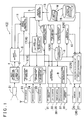
- FIG. 1 is a block diagram that schematically shows an example of a configuration of a navigation apparatus that includes a vehicle behavior learning apparatus;
- FIG. 2 is a drawing that shows an example of a configuration of information stored in a map database and a feature database
- FIG. 3 is a drawing that shows an example of image information
- FIG. 4 is a drawing that shows an example of map information for the surroundings of a vehicle for which the vehicle behavior learning apparatus is used;
- FIG. 5 is a block diagram that schematically shows an example of a configuration of a learned behavior database
- FIG. 6 is a block diagram that schematically shows another example of a configuration of the learned behavior database
- FIG. 7 is a flowchart that shows an example of a method for learning a behavior of the vehicle
- FIG. 8 is a flowchart that shows an example of a method for predicting a behavior of the vehicle
- FIG. 9 is a drawing that shows an example in which a behavior of the vehicle is learned based on route guidance provided by the navigation apparatus.
- FIG. 10 is a drawing that shows an example in which a result of prediction for a behavior of the vehicle is utilized in route guidance provided by the navigation apparatus.
- FIG. 1 is a block diagram that schematically shows an example of a configuration of a navigation apparatus 1 that includes a vehicle behavior learning apparatus 2 .
- FIG. 2 is a drawing for explaining an example of a configuration of information stored in a map database 13 and a feature database 15 that are shown in FIG. 1 .
- the navigation apparatus 1 includes functional elements such as the vehicle behavior learning apparatus 2 , the map database 13 , an application program 16 , and a guidance information outputting unit 28 .
- the vehicle behavior learning apparatus 2 includes functional elements such as a vehicle position information obtaining unit 3 , an image information obtaining unit 4 , a feature information obtaining unit 5 , an image recognizing unit 6 , a behavior detecting unit 7 , a detection result storing unit 8 , and a learned behavior extracting unit 9 .
- These functional elements are structured with one or both of hardware and software (i.e., programs), while a controller such as a microprocessor or a DSP (digital signal processor) is used as a core element.
- a controller such as a microprocessor or a DSP (digital signal processor) is used as a core element.
- these functional elements perform processes on various types of input data, as a result of a collaboration of the hardware and the software. The details of these functional elements are explained below.
- the map database 13 is a database that stores therein a plurality of pieces of map information M each of which corresponds to a predetermined divided area and a plurality of pieces of feature information F that are kept in correspondence with the plurality of pieces of map information M.
- FIG. 2 shows an example of a configuration of the map information M stored in the map database 13 and the feature information F stored in the feature database 15 .
- the map database 13 stores therein a road network layer m 1 , a road shape layer m 2 , and a feature layer m 3 .
- the map information M stored in the map database 13 is structured with the information stored in the layers m 1 , m 2 , and m 3 .
- the feature information F stored in the feature database 15 is structured with the information stored in the feature layer m 3 .
- the road network layer m 1 is a layer that shows connection information among the roads.
- the road network layer m 1 is configured so as to include information of a large number of nodes n each of which has position information on a map expressed with coordinates based on, for example, the latitude and the longitude, and information of a large number of links k each of which structures a road by linking two of the nodes n.
- link information each of the links k has information showing the type of the road (e.g., an expressway, a toll road, a national road, or a prefectural road) and the link length.
- the road shape layer m 2 is stored in correspondence with the road network layer m 1 and shows the shapes of the roads.
- the road shape layer m 2 is configured so as to include information of a large number of road shape complementary points s and information of the road width w.
- Each of the road shape complementary points s is positioned between two nodes n (i.e., positioned on a link k) and has position information on a map expressed with coordinates based on, for example, the latitude and the longitude.
- the feature layer m 3 is configured in correspondence with the road network layer m 1 and the road shape layer m 2 .
- the feature layer m 3 is a layer that stores therein the feature information F that is the information of various types of features that are positioned on the roads or in the surroundings of the roads.
- Such features include road markers (e.g., paint markers) that are provided on the surface of the roads.
- road markers e.g., paint markers
- features that are related to such road markers include: carriageway lines (including various types of carriageway lines such as solid lines, broken lines, and double lines) that divide the roads into lanes; traffic separation markers showing different moving directions that designate the moving directions for the vehicles in each lane; pedestrian crossings; stop lines; speed limit signs; and zebra zones.
- the features of which the feature information F is stored may include other types of features such as traffic lights, road signs, overpasses, and tunnels.
- the feature information F includes, as the contents thereof, position information and attribute information of the features.
- the position information includes information of the position (e.g., the coordinates based on, for example, the latitude and the longitude) of the representative points of the features on the map that are kept in correspondence with, for example, the links k or the nodes n as well as the information of the orientation directions of the features.
- each of the representative points is specified at the center of the feature in the longitudinal direction and the width direction.
- the attribute information includes configuration information that shows the configuration of each of the features and type information that shows the type of each of the features.
- the configuration information includes information of the shape, the size, and the color of each of the features.
- the type information is information that shows the type of the road markers such as “carriageway line” (including the type of the line such as a solid line, a broken line, or double lines), “traffic separation marker showing a moving direction,” and “pedestrian crossing.”
- the vehicle position information obtaining unit 3 obtains vehicle position information L showing a current position of the vehicle, which is simply referred to as a “vehicle position.”
- vehicle position information obtaining unit 3 is connected to a GPS receiver 23 , a direction sensor 24 , and a distance sensor 25 .
- the GPS receiver 23 is a device that receives GPS signals from a GPS (Global Positioning System) satellite.
- the GPS signals are usually received at one-second intervals and are output to the vehicle position information obtaining unit 3 .
- the vehicle position information obtaining unit 3 analyzes the GPS signals received from the GPS satellite and obtains information including the current position (e.g., the coordinates based on, for example, the latitude and the longitude), the moving direction, and the traveling speed of the vehicle.
- the direction sensor 24 detects the moving direction of the vehicle and changes in the moving direction of the vehicle and outputs a detection result to the vehicle position information obtaining unit 3 .
- the direction sensor 24 is configured with, for example, a gyro sensor, a geomagnetic sensor, an optical rotation sensor or a rotation-type resistor volume control that is attached to the rotating portion of the steering wheel, or an angle sensor that is attached to the wheel portion.
- the distance sensor 25 detects the vehicle speed and a traveling distance of the vehicle and outputs, as the detection results, information of the vehicle speed and the traveling distance to the vehicle position information obtaining unit 3 .
- the distance sensor 25 is configured with, for example, a vehicle speed pulse sensor that outputs a pulse signal every time the drive shaft or the wheels of the vehicle rotate by a certain amount or a yaw/G sensor that detects an acceleration of the vehicle and a circuit that integrates the detected acceleration.
- the vehicle position information obtaining unit 3 performs a calculation process according to a publicly-known method so as to identify the vehicle position, based on the outputs from the GPS receiver 23 , the direction sensor 24 , and the distance sensor 25 described above. Also, the vehicle position information obtaining unit 3 adjusts the vehicle position so that the vehicle position is located on a road indicated in the map information M, by performing a publicly-known map matching process based on the map information M for the surroundings of the vehicle position that has been obtained from the map database 13 .
- the information of the vehicle position that is obtained through the process described above may have errors related to the detection accuracy of the sensors 23 , 24 , and 25 . Also, the information of the vehicle position that is obtained through the process described above has a possibility of not being able to accurately identify the lane in which the vehicle is being driven, when the road on which the vehicle is driven has more than one lane. To cope with these situations, according to the present example, a lane identifying unit 17 , which is explained later, supplies lane identifying information J that identifies the lane in which the vehicle is positioned on the road on which the vehicle is being driven, to the vehicle position information obtaining unit 3 .
- the vehicle position information obtaining unit 3 obtains the vehicle position information L that includes the information of the current position of the vehicle expressed with the coordinates based on, for example, the latitude and the longitude, the information of the moving direction of the vehicle, and the lane identifying information J related to the lane in which the vehicle is being driven, based on the calculation result that identifies the vehicle position and the lane identifying information J supplied by the lane identifying unit 17 .
- the vehicle position information L is output to a vehicle position information correcting unit 11 , the feature information obtaining unit 5 , a recognition condition specifying unit 14 , and a navigation calculating unit 12 .
- the image information obtaining unit 4 obtains image information G of the surroundings of the vehicle position that has been taken by an image pickup device 21 .
- the image pickup device 21 is configured with, for example, a camera that includes an image pickup element.
- the image pickup device 21 is provided in such a position in which at least an image of the surface of the road in the surroundings of the vehicle (i.e., the vehicle position) can be taken.
- the image pickup device 21 may be configured with, for example, a rear-view camera.
- the image information obtaining unit 4 obtains, at certain time intervals, image pickup information that has been taken by the image pickup device 21 via a frame memory (not shown) or the like.
- the time intervals at which the image information G is obtained may be, for example, approximately 10 milliseconds to 50 milliseconds.
- the image information obtaining unit 4 sequentially obtains a plurality of frames of image information G that have been taken by the image pickup device 21 .
- the image information G that has been obtained by the image information obtaining unit 4 is output to the image recognizing unit 6 .
- the feature information obtaining unit 5 extracts, out of the feature database 15 , a piece of feature information F for a target feature ft that serves as a target of an image recognition process.
- the feature information obtaining unit 5 obtains, out of the feature database 15 , the piece of feature information F corresponding to the one target feature ft that is specified by the recognition condition specifying unit 14 , which is explained later.
- the obtained piece of feature information F includes, as explained above, the position information and the configuration information of the target feature ft.
- the piece of feature information F corresponding to the target feature ft that has been extracted by the feature information obtaining unit 5 is output to the image recognizing unit 6 , the vehicle position information correcting unit 11 , the detection result storing unit 9 , a behavior predicting unit 10 , and the recognition condition specifying unit 14 .
- the feature information obtaining unit 5 extracts, out of the feature database 15 , a piece of feature information F corresponding to a carriageway line in the surroundings of the vehicle position on the road on which the vehicle is being driven, based on the vehicle position information L.
- the piece of feature information F corresponding to the carriageway line that has been extracted by the feature information obtaining unit 5 is output to the image recognizing unit 6 and the lane identifying unit 17 .
- the recognition condition specifying unit 14 specifies recognition conditions used in an image recognition process performed by the image recognizing unit 6 .
- the recognition condition specifying unit 14 specifies the target feature ft that serves as the target of the image recognition process.
- the target feature ft is selected out of one or more features that are positioned in the surroundings of the vehicle position within an image pickup area used by the image pickup device 21 , among the features for which the pieces of feature information F are stored in the feature database 15 .
- the recognition condition specifying unit 14 specifies, as the target feature ft, one feature that is positioned closest to the vehicle in terms of the moving direction of the vehicle in the lane in which the vehicle is being driven, based on the vehicle position information L that has been obtained by the vehicle position information obtaining unit 3 and the feature information F that is stored in the feature database 15 .
- the range in which the target feature ft is searched for in terms of the moving direction of the vehicle is defined so as to be within a predetermined distance from the vehicle. Accordingly, when no feature is present within the predetermined distance from the vehicle in terms of the moving direction of the vehicle, no target feature ft is specified.
- the recognition condition specifying unit 14 specifies an image recognition range within which the image recognition process is performed on the image information G with respect to each target feature ft.
- the image recognition range is a range that is defined in the moving direction of the vehicle from the vehicle position.
- the image recognition range is specified according to the length of the target feature ft in the moving direction of the vehicle position and is calculated based on the configuration information contained in the feature information F.
- the image recognition range is specified so as to be a longer range when the target feature ft is a speed limit indicator that is longer in terms of the moving direction of the vehicle than when the target feature ft is a stop line.
- the information of the image recognition range that has been specified is output to the image recognizing unit 6 .
- the image recognizing unit 6 performs the image recognition process on the image information G within the specified image recognition range, with respect to the target feature ft.
- the image recognizing unit 6 performs the image recognition process on the image information G that has been obtained by the image information obtaining unit 4 .
- the image recognizing unit 6 performs the image recognition process on the image information G within the range that has been defined as the image recognition range by the recognition condition specifying unit 14 .
- the image recognizing unit 6 performs the image recognition process of the target feature ft by using the piece of feature information F corresponding to the target feature ft that has been extracted by the feature information obtaining unit 5 .
- the image recognizing unit 6 extracts a piece of image information G corresponding to the image recognition range, out of the image information G that has been obtained by the image information obtaining unit 4 .
- the correction information for the image pickup device 21 is information (parallel movement, rotation, and camera internal parameters) that is based on the position in which the image pickup device 21 is attached to the vehicle, the angle at which the image pickup device 21 is attached, and the angle of view.
- the image recognizing unit 6 extracts the piece of image information G corresponding to the image recognition range, based on the information of the image pickup area of the piece of image information G that has been obtained in the procedure described above. Specifically, the image recognizing unit 6 performs a binarization process or an edge detection process on the extracted piece of image information G and extracts outline information of the feature (e.g., a road marker) contained in the piece of image information G. Subsequently, the image recognizing unit 6 compares the outline information of the feature that has been extracted with the configuration information contained in the piece of feature information F corresponding to the target feature ft that has been obtained by the feature information obtaining unit 5 and judges whether the outline information matches the configuration information.
- the image recognizing unit 6 compares the outline information of the feature that has been extracted with the configuration information contained in the piece of feature information F corresponding to the target feature ft that has been obtained by the feature information obtaining unit 5 and judges whether the outline information matches the configuration information.
- the image recognizing unit 6 judges that the image recognition process for the target feature ft has successfully been performed and outputs the image recognition result to the vehicle position information correcting unit 11 .
- the vehicle position information correcting unit 11 does not perform the process of correcting the vehicle position information L.
- the image recognizing unit 6 performs an image recognition process for the carriageway line in the surroundings of the vehicle, by using the piece of feature information F that corresponds to the carriageway line in the surroundings of the vehicle position on the road on which the vehicle is being driven and that has been extracted by the feature information obtaining unit 5 .
- the image recognizing unit 6 performs a binarization process or an edge detection process on the piece of image information G that has been obtained by the image information obtaining unit 4 and extracts the outline information of the feature (e.g., the road marker) contained in the piece of image information G.
- the image recognizing unit 6 performs a process of recognizing the position and the type of the carriageway line in the surroundings of the vehicle, based on the outline information of the feature that has been extracted and the configuration information contained in the piece of feature information F that corresponds to the carriageway line.
- the image recognizing unit 6 then outputs an image recognition result of the carriageway line to the lane identifying unit 17 .
- the vehicle position information correcting unit 11 corrects the vehicle position information L, based on the result of the image recognition process performed by the image recognizing unit 6 and the position information of the target feature ft that is contained in the piece of feature information F obtained by the feature information obtaining unit 5 .
- the vehicle position information correcting unit 11 corrects the vehicle position information L along the moving direction of the vehicle. Specifically, at first, the vehicle position information correcting unit 11 calculates a positional relationship between the vehicle and the target feature ft at the time when the piece of image information G that contains the image of the target feature ft is obtained, based on the image recognition result obtained by the image recognizing unit 6 and the correction information for the image pickup device 21 .
- the vehicle position information correcting unit 11 calculates position information of the vehicle with a high level of precision while using the position information (i.e., the piece of feature information F) of the target feature ft in terms of the moving direction of the vehicle as a reference, based on the result of the calculation of the positional relationship between the vehicle and the target feature ft and the position information of the target feature ft contained in the piece of feature information F. Subsequently, the vehicle position information correcting unit 11 corrects the information of the current position of the vehicle in terms of the moving direction thereof that is contained in the vehicle position information L obtained by the vehicle position information obtaining unit 3 , based on the position information of the vehicle with the high level of accuracy. As a result, the vehicle position information obtaining unit 11 has obtained the vehicle position information L that has been corrected and has a high level of accuracy.
- the position information obtaining unit 11 has obtained the vehicle position information L that has been corrected and has a high level of accuracy.
- the lane identifying unit 17 obtains the lane identifying information J that identifies the lane in which the vehicle is positioned on the road on which the vehicle is being driven.
- the lane identifying unit 17 obtains the lane identifying information J by performing the calculation process to identify the lane in which the vehicle is being driven, based on the piece of feature information F corresponding to the carriageway line in the surroundings of the vehicle position on the road on which the vehicle is driven and the result of the image recognition process performed on the carriageway line contained in the image information G.
- the lane identifying unit 17 identifies the lane in which the vehicle is driven, based on the type (i.e., a solid line, a broken line, or double lines) and the positioning of the carriageway line in the surroundings of the vehicle that is indicated in the result of the image recognition process performed by the image recognizing unit 6 and the configuration information contained in the piece of feature information F corresponding to the carriageway line in the surroundings of the vehicle position.
- the type i.e., a solid line, a broken line, or double lines
- the lane in which the vehicle is driven is identified as the middle lane among the three lanes.
- a carriageway line drawn with a broken line is provided on either side of the position of vehicle that is at the center of the image in the width direction thereof.
- a carriageway line drawn with a solid line is provided on the outside of each of the broken lines.
- the road on which the vehicle is driven has three lanes, while a piece of feature information F indicates that there is a carriageway line drawn with a solid line on either side of the road in the width direction thereof, and also another piece of feature information F indicates that there are carriageway lines drawn with broken lines that separate the road into the lanes and positioned closer to the center of the road in the width direction thereof. Accordingly, by comparing these pieces of information, the lane identifying unit 17 identifies that the lane in which the vehicle is being driven is the middle lane among the three lanes.
- the lane identifying unit 17 also identifies the lane in which the vehicle is being driven by judging whether the vehicle has gone over any carriageway line so as to change the lane, based on the position information of the carriageway line indicated in the result of the image recognition process.
- the lane identifying unit 17 performs the calculation process to identify the lane only when it is necessary to identify the lane in which the vehicle is being driven, in other words, only when the road on which the vehicle is driven has more than one lane on the side of the road that corresponds to the moving direction of the vehicle.
- the lane identifying unit 17 supplies the lane identifying information J, which is the information identifying the lane in which the vehicle is driven, to the vehicle position information obtaining unit 3 .
- the vehicle position information obtaining unit 3 generates the vehicle position information L that includes the lane identifying information J regarding the lane in which the vehicle is being driven. Consequently, according to the present example, together with the vehicle position information obtaining unit 3 , the lane identifying unit 17 functions as a vehicle position information obtaining unit 18 .
- the behavior detecting unit 7 detects a behavior of the vehicle that is performed within a predetermined range from a position in which the image recognition process for the target feature has successfully been performed by the image recognizing unit 6 . As shown in FIG. 1 , the behavior detecting unit 7 detects the behavior of the vehicle by receiving inputs from various types of switches and various types of sensors that are included in the vehicle and function as behavior inputting units.
- the various types of switches include, for example, an air conditioning switch 31 , a lighting switch 33 , a window switch 35 , and an audio operating switch (not shown).
- the various types of sensors include, for example, a vibration sensor 37 , an illuminance sensor 39 , an acceleration sensor (not shown), an accelerator sensor (not shown), and a brake sensor (not shown).
- the air conditioning switch 31 is a switch for changing the settings for an air conditioner or a heater and switching the settings between “introducing air from the outside” and “having air circulated within the vehicle interior.”
- the lighting switch 33 is a switch for turning on and off the lamp devices of the vehicle and changing the settings between a high beam and a low beam.
- the window switch 35 is a switch used for opening and closing the windows.
- the vibration sensor 37 is a sensor that detects a vibration transmitted to the vehicle. The result of the vibration detection is, for example, forwarded to a controlling device for an active suspension so that the suspension level is adjusted to an appropriate level of stiffness.
- the illuminance sensor 39 is a sensor that detects the brightness on the outside of the vehicle.
- the result of the illuminance detection is, for example, forwarded to a controlling device for the lamp devices so that the control to turn on and off the lamp devices is automatically exercised.
- the acceleration sensor is a sensor that detects the acceleration related to increases and decreases of the speed of the vehicle.
- the accelerator sensor is a sensor that detects an amount by which the accelerator pedal is depressed by the driver (i.e., the opening degree of the accelerator).
- the brake sensor is a sensor that detects an amount by which the brake pedal is depressed or a brake depressing force by the driver.
- behaviors of the vehicle detected by the behavior detecting unit 7 include receiving of operations performed by the driver while the recipient is any of the constituent elements of the vehicle and operations of the vehicle.
- the operations of the vehicle include operations of any of the constituent elements of the vehicle and operations of the entire vehicle that are caused by an operation performed by the driver as well as operations of any of the constituent elements of the vehicle and operations of the entire vehicle that are caused by an external factor affecting the vehicle from the outside thereof.
- the behavior detecting unit 7 detects an operation performed on any of the various types of switches such as the air conditioning switch 31 , the lighting switch 33 , the window switch 35 , and the audio operating switch as well as an operation that is performed by the driver and detected by any of the various types of sensors such as the accelerator sensor and the brake sensor.
- the behavior detecting unit 7 detects operations of the vehicle that are detected by any of the various types of sensors as a result of the receiving of the operations performed by the driver. Examples of such operations include a change in the moving direction of the vehicle that is caused by a steering operation performed by the driver and is detected by the direction sensor 24 ; a change in the acceleration of the vehicle that is caused by an operation of the accelerator pedal or the brake pedal performed by the driver and is detected by the acceleration sensor; and a change in the shift speed of the transmission that is caused by an operation on the gear shift or the accelerator performed by the driver.
- the behavior detecting unit 7 detects an operation of the navigation apparatus 1 based on an input to a touch panel that is integrally provided with a monitor 26 of the navigation apparatus 1 or an input to a remote control.
- Examples of such operations of the navigation apparatus 1 include, for instance, obtainment of congestion information, a change in the scale with which a map is displayed, a change in the brightness level of the screen display, and a change in a guidance route, each of which is caused by an operation performed by the driver.
- the behavior detecting unit 7 detects an operation of the vehicle that is caused by an external factor and is detected by any of the various types of sensors. Examples of such operations include: vibrations of the vehicle that are caused by driving over a bump or on a rough road surface and are detected by the vibration sensor 37 ; a change in the acceleration of the vehicle that is caused by driving on a slope and is detected by the acceleration sensor; and a change in the moving direction of the vehicle that is caused by driving on a curve and is detected by the direction sensor 24 .
- the behavior detecting unit 7 detects the behavior of the vehicle that is performed within the predetermined range from the target feature that has been specified based on the vehicle position information L and for which the image recognition process has successfully been performed by the image recognizing unit 6 . For example, When the vehicle turns to the right or to the left within the predetermined range past a position in which a road marker indicating that the vehicle is approaching a pedestrian crossing (e.g., a diamond symbol) is detected, the behavior detecting unit 7 detects the behavior of turning to the right or to the left.
- a road marker indicating that the vehicle is approaching a pedestrian crossing e.g., a diamond symbol
- the behavior detecting unit 7 can detect this behavior based on the change in the moving direction of the vehicle that is detected by the direction sensor 24 , an input from a blinker that serves as one of the various types of switches, and an input from a steering angle sensor that detects a rotation of the steering device and serves as one of the various types of sensors.
- the behavior detecting unit 7 outputs the detected behavior as behavior detection information B, while keeping the behavior detection information B in correspondence with the vehicle position information L.
- the detection result storing unit 8 stores therein, based on the vehicle position information L, the behavior detection information B that indicates a result of the detection of the behavior of the vehicle and has been obtained by the behavior detecting unit 7 , while keeping the behavior detection information B in correspondence with information of the detection position in which the behavior has been detected.
- the information of the detection position in which the behavior has been detected is coordinate information that indicates the detection position of the behavior.
- the coordinate information that indicates the detection position of the behavior is derived based on the coordinates of the current position of the vehicle that is indicated in the vehicle position information L and corresponds to the time at which the behavior is detected.
- the detection result storing unit 8 may store therein the behavior detection information for each individual person.
- the learned behavior extracting unit 9 functions as a learned behavior extracting unit 29 that extracts the behavior of the vehicle as a learned behavior and outputs, as learned behavior information R, attribute information and position information of the learned behavior that are kept in correspondence with the piece of feature information F of the target feature for which the image recognition process has successfully been performed.
- the position information of the learned behavior that is output as the learned behavior information R is coordinate information that indicates the position of the learned behavior.
- the coordinate information that indicates the position of the learned behavior is derived based on the information of the detection position of the behavior that has been stored in the detection result storing unit 8 while being kept in correspondence with the behavior detection information B, which is, in the present example, the coordinate information that indicates the detection position of the behavior, as explained above.
- the learned behavior information R that has been output is stored into the learned behavior database 19 .
- the learned behavior database 19 also functions as the learned behavior extracting unit 29 .
- the learned behavior is such a behavior of the vehicle that is repeatedly detected based on a plurality of pieces of behavior detection information B that indicate mutually the same behavior of the vehicle and have been stored in the detection result storing unit 8 while the vehicle is being driven through the same location a plurality of times.
- Examples of such a behavior include a behavior to operate the blinker to indicate a left turn at a point of location and turn the vehicle to the left and a behavior to change the setting of the air conditioning device at a point of location from “introducing air from the outside” to “having air circulated within the vehicle interior.”
- the learned behavior database 19 is a vehicle adaptive database 200 that is managed and maintained for each individual vehicle, as shown in FIG. 5 .
- the vehicle includes a device that identifies individual persons like the driver, it is acceptable to use an individual-person adaptive database, in addition.
- the map database 13 and the feature database 15 are each a common database 100 that is managed and maintained with respect to the roads, without dependency on individual vehicles.
- the common database 100 may be configured so that communication is allowed with the database management center 300 in a wired or wireless manner.
- the information such as map information MC and feature information FC that are respectively stored in the map database 13 C and the feature database 15 C provided in the database management center 300 are updated on an as-needed basis.
- the map database 13 and the feature database 15 for the vehicle it is possible to update, through communication, the contents of the map information M and the feature information F that are respectively stored therein, with the newest information.
- the learned behavior extracting unit 9 When the learned behavior extracting unit 9 is connected to a plurality of vehicles in such a manner that communication is allowed therebetween and also an operation of the vehicle that is caused by an external factor affecting the vehicle from the outside thereof is detected as a behavior of the vehicle, the learned behavior may be a behavior explained below.
- FIG. 6 shows an example in which the learned behavior extracting unit 9 A of the vehicle is connected to a learned behavior extracting unit 9 B of another vehicle in such a manner that communication is allowed therebetween via the database management center 300 . Needless to say, it is acceptable to have another arrangement in which the learned behavior extracting units 9 A and 9 B are directly connected to each other in such a manner that communication is allowed therebetween. In the example shown in FIG.
- the learned behavior may be a behavior of the vehicle that is detected with a reproducible characteristic, based on a plurality of pieces of behavior detection information that indicate the behaviors of the plurality of vehicles and have respectively been stored in the detection result storing units of the vehicles, while the vehicles are being driven through mutually the same location.
- the behavior may be the same type of vibrations that are detected in a plurality of vehicles at a certain point of location with the use of their respective vibration sensors 37 .
- the vibrations are caused by a bump on the road.
- the behavior is considered to have no dependency on the individual vehicles. Accordingly, even if each of the vehicles detects the vibration only one time, if the plurality of vehicles detect the same type of vibrations at substantially the same point of location, the behavior is considered to be a behavior that is detected with a sufficient reproducible characteristic.
- the learned behavior database 19 serves as both the vehicle adaptive database 200 that is managed and maintained for individual vehicles and the common database 100 that is managed and maintained without dependency on individual vehicles.
- the learned behavior database 19 stores therein learned behavior information Ra that is managed and maintained for each individual vehicle (or each individual person) and learned behavior information Rb that is managed and maintained with respect to the roads without dependency on the individual vehicles.
- the learned behavior information Ra belongs to the vehicle adaptive database 200
- the learned behavior information Rb belongs to the common database 100 .
- the information such as the map information MC and the feature information FC that are respectively stored in the map database 13 C and the feature database 15 C provided in the database management center 300 is updated on an as-needed basis.
- the map database 13 and the feature database 15 for the vehicle it is possible to update, through communication, the contents of the map information M and the feature information F that are stored therein, with the newest information.
- the database management center 300 has a learned behavior database 19 C that is managed and maintained with the use of the learned behavior extracting unit 9 that is connected to a plurality of vehicles in such a manner that communication is allowed therebetween.
- Learned behavior information RC that is stored in the learned behavior database 19 C is updated on an as-needed basis.
- the learned behavior database 19 for the vehicle it is possible to update, through communication, the learned behavior information Rb that is among the pieces of data stored therein and is managed and maintained without dependency on the individual vehicles.
- the behavior predicting unit 10 functions as a behavior predicting unit according to the present example that predicts a behavior kept in correspondence with a target feature, based on the learned behavior information R.
- the behavior predicting unit 10 outputs a result of the prediction to various types of controlling devices included in the vehicle like the navigation calculating unit 12 .
- the various types of controlling devices include controlling devices included in the vehicle that reproduce an operation performed by the driver and controlling devices that optimize an operation of the vehicle that is caused by an operation performed by the driver or an external factor. Specific examples will be explained later.
- the exemplary methods may be implemented, for example, by one or more components of the above-described apparatus 1 .
- the exemplary structure of the above-described apparatus 1 may be referenced in the description, it should be appreciated that the structure is exemplary and the exemplary methods need not be limited by any of the above-described exemplary structure.
- a computation processing device included in the navigation apparatus 1 operates as a computer that executes a vehicle behavior learning program that constitutes the functional elements described above.
- the vehicle position information obtaining unit 3 obtains the vehicle position information L that indicates a current position of the vehicle (step # 1 ).
- the image information obtaining unit 4 obtains the image information G of the surroundings of the vehicle (step # 2 ).
- the feature information obtaining unit 5 obtains a piece of feature information F corresponding to the surroundings of the vehicle, based on the vehicle position information L (step # 3 ).
- the image recognizing unit 6 performs a recognition process on the target future contained in the image information G, based on the piece of feature information F, whereas the vehicle position information correcting unit 11 corrects the vehicle position information L (step # 4 ).
- the behavior detecting unit 7 is configured so as to detect a behavior of the vehicle that is performed within a small range in which the error in the vehicle position information L is considered to be relatively small. In other words, the behavior detecting unit 7 detects a behavior of the vehicle that is performed within a predetermined range from a position in which the image recognition process for the target feature has successfully been performed by the image recognizing unit 6 (step # 11 ).
- the detected behavior includes at least one of (a) receiving of an operation performed by the driver while the recipient is any of the constituent elements of the vehicle, and (b) an operation of the vehicle that is caused by an operation performed by the driver or an external factor affecting the vehicle from the outside thereof.
- behavior detection information B that indicates a result of the detection of the behavior of the vehicle that has been obtained by the behavior detecting unit 7 is stored into the detection result storing unit 8 in correspondence with the information of the detection position in which the behavior has been detected (step # 12 ).
- the learned behavior extracting unit 9 extracts a learned behavior based on the behavior detection information B and outputs learned behavior information R (step # 13 ).
- the repeatedly-detected behavior of the vehicle is extracted as the learned behavior.
- Output as the learned behavior information R are the attribute information and the position information of the learned behavior that are kept in correspondence with a piece of feature information of the target feature for which the image recognition process has successfully been performed.
- the learned behavior information R is registered into the learned behavior database 19 and will be referred to by the various types of controlling devices included in the vehicle.
- the learned behavior extracting step # 13 is performed while sharing pieces of behavior detection information B indicating a behavior that has been detected from a plurality of vehicles and is kept in correspondence with the information of the detection positions in which the behavior has been detected.
- the learned behavior information R are the attribute information and the position information of the learned behavior that are kept in correspondence with the piece of feature information of the target feature for which the image recognition process has successfully been performed.
- the behavior of the vehicle is learned.
- the procedure for predicting a behavior of the vehicle by using the learned behavior information R that has been learned will be explained.
- the vehicle position information obtaining step # 1 , the image information obtaining step # 2 , the feature information obtaining step # 3 , and the image recognition step # 4 are performed.
- the vehicle is in such a state that the vehicle position is recognized with a high level of accuracy.
- step # 5 it is judged whether the vehicle is in such a state that the vehicle position is recognized with a high level of accuracy. In the case where the vehicle is in a high-precision recognition state, the following step, namely # 21 , will be performed so that a behavior of the vehicle can be predicted.
- the behavior predicting unit 10 predicts a behavior that is kept in correspondence with the target feature, based on the learned behavior information R (step # 21 ).
- the behavior of the vehicle detected at the behavior detecting step # 11 includes at least one of (a) receiving of an operation performed by the driver while the recipient is any of the constituent elements of the vehicle, and (b) an operation of the vehicle that is caused by an operation performed by the driver or an external factor affecting the vehicle from the outside thereof.
- learned behavior information R is output to any of the controlling devices included in the vehicle that reproduce an operation performed by the driver.
- learned behavior information R is output to any of the controlling devices that optimize an operation of the vehicle that is caused by an operation performed by the driver or an external factor.
- FIG. 9 is a drawing for explaining an example in which a behavior of the vehicle is learned based on a locus of the vehicle position information L obtained by the vehicle position information obtaining unit 3 .
- a vehicle 50 for which the vehicle behavior learning apparatus 2 is used is being driven on a main road K 1 and turns left at an intersection N 3 onto a small street K 3 , before reaching a major intersection N 2 at which the main road K 1 crosses another main road K 2 .
- the main road K 2 and the small street K 3 that run parallel to each other are positioned close to each other.
- the vehicle position information obtaining unit 3 may perform a map matching process in such a manner that the current position of the vehicle 50 indicated in the vehicle position information L is placed on a wrong road.
- the map matching process may be performed in such a manner that the current position of the vehicle 50 indicated in the vehicle position information L is placed on the main road K 2 as shown with a broken line in FIG. 9 , so that the position of the vehicle 50 indicated in the vehicle position information L is displayed on the monitor 26 with a vehicle position mark 60 .
- the result will be corrected manually by the driver or automatically by the navigation calculating unit 12 .
- the vehicle position mark 60 indicating the wrong position is displayed on the monitor 26 for at least a short period of time.
- a driver of the vehicle 50 operates the blinker before reaching the intersection N 3 , operates the brake so as to reduce the speed of the vehicle 50 , and steers the wheels to turn to the left at the intersection N 3 .
- These operations performed by the driver on the blinker, the brake, and the steering device are detected by the behavior detecting unit 9 as a behavior of the vehicle.
- the change in the moving direction of the vehicle 50 that is detected by the direction sensor 24 when the vehicle 50 turns to the left is also detected by the behavior detecting unit 9 as a behavior of the vehicle 50 that is caused as a result of the operation performed by the driver.
- the vehicle 50 is driven past the intersection N 1 before reaching the intersection N 3 .
- pedestrian crossings C 1 and C 2 which serve as features. These features are recognized as target features in the image recognition process. In the present example, these features are recognized as target features of which the ends (shown with squares in FIG. 9 ) on the moving direction side of the vehicle 50 are shown in the position information. While one or both of these target features are used as a reference, the turning operation (i.e., turning to the left in the present example) of the vehicle 50 performed at the intersection N 3 is stored into the detection result storing unit 8 as a behavior of the vehicle.
- behavior detection information B that indicates the detection result of the vehicle behavior is stored into the detection result storing unit 8 , while being kept in correspondence with the information of the detection position of the behavior based on the vehicle position information L that has been corrected by the vehicle position information correcting unit 11 , while one or both of the pedestrian crossings C 1 and C 2 serving as the target features are used as the reference.
- the detection result storing unit 8 stores therein a plurality of pieces of behavior detection information B that indicate mutually the same behavior that is performed by the vehicle 50 the plurality of times.
- the learned behavior extracting unit 9 extracts the behavior of the vehicle 50 that has repeatedly been detected, as a learned behavior.
- Stored into the learned behavior database 19 as the learned behavior information R are the attribute information and the position information of the learned behavior that are kept in correspondence with the piece of feature information of the target feature for which the image recognition process has successfully been performed.
- the attribute information is information that identifies the turning to the left at the intersection N 3 and the operation performed on the blinker.
- the position information is coordinate information that indicates the position of the learned behavior.
- the position information is derived based on the information of the detection position of the behavior that is kept in correspondence with the behavior detection information B stored in the detection result storing unit 8 .
- the position indicated in the position information in the learned behavior information R is a position in the intersection N 3 .
- FIG. 10 is a drawing for explaining an example in which a result of the prediction for the behavior of the vehicle is utilized by the navigation calculating unit 12 in displaying the vehicle position.
- the learned behavior information R of the vehicle 50 is stored in the learned behavior database 19 , the vehicle 50 is being driven on the main road K 1 .
- the image recognizing unit 6 recognizes the pedestrian crossings C 1 and C 2 as target features.
- the behavior predicting unit 10 obtains the learned behavior information R that is kept in correspondence with the pedestrian crossings C 1 and C 2 and predicts that there is a high possibility that the vehicle 50 turns to the left at the intersection N 3 .
- the behavior predicting unit 10 outputs the result of the prediction for the behavior to the navigation calculating unit 12 .
- the navigation calculating unit 12 judges that the vehicle 50 has entered the small street K 3 instead of the main road K 2 and causes the vehicle position mark 60 to be displayed on the small street K 3 on the monitor 26 .
- the behavior predicting unit 10 outputs the result of the prediction for the behavior of the vehicle to the vehicle position information obtaining unit 3 so that the vehicle position information L can be corrected.
- the vehicle behavior learning apparatus 2 it is possible to improve the level of accuracy in the vehicle position display and the route guidance provided by the navigation apparatus 1 .
- the behavior detecting unit 7 detects, as a behavior of the vehicle 50 , the operation that is performed by the driver and received by the constituent elements of the vehicle 50 as well as the operation of the vehicle 50 that is caused as a result of the operation performed by the driver.
- an example will be explained in which an operation of the vehicle 50 that is caused by an external factor affecting the vehicle 50 from the outside thereof is detected as a behavior.
- a system that controls, based on road information provided by the navigation apparatus 1 , an attenuation in the suspension of the vehicle 50 , so as to improve the steering stability while the vehicle is driven on a curve and optimize the attenuating force of vibrations while the vehicle is driven over a bump.
- the system is called a navigation collaboration suspension system.
- a navigation collaboration suspension system is realized mainly by using the vehicle position information L that is obtained by the navigation apparatus 1 through the GPS receiver 23 , the direction sensor 24 , the distance sensor 25 , and the like.
- the vehicle position information L may have an error, there is a possibility that the control on the suspension may be exercised in a position that is different from an optimal position.
- the behavior learning apparatus 2 when used, the behavior of the vehicle such as being driven on a curve or over a bump is detected as behavior detection information B by the vibration sensor 37 that detects the suspension, the direction sensor 24 , and/or the yaw/G sensor.
- the behavior detection information B is stored in the learned behavior database 19 as the learned behavior information R, while being kept in correspondence with the piece of feature information F.
- the learned behavior information R indicates a behavior of the vehicle 50 that has repeatedly been detected and extracted, based on a plurality of pieces of behavior detection information B that indicate mutually the same behavior of the vehicle 50 .
- the behavior is based on the operation of the vehicle 50 that is caused by the external factor affecting the vehicle 50 from the outside thereof.
- the dependency on the driver and the vehicle is low, while the dependency on the road itself is high. Consequently, as explained with reference to FIG. 6 , it is possible to consider that the learned behavior information R indicates a behavior of the vehicle 50 that has been detected and extracted with a reproducible characteristic, based on a plurality of pieces of behavior detection information B that have respectively been stored in the detection result storing units 8 of the plurality of vehicles while the plurality of vehicles are being driven through mutually the same location.
- the behavior predicting unit 10 predicts the behavior of the vehicle, such as being driven over a bump or on a curve, that is kept in correspondence with the corresponding target feature. Based on the result of the prediction, the navigation collaboration suspension system is controlled. Consequently, for example, in the case where a road has a bump in a specific place, it is possible to predict that the vehicle will receive vibrations and/or a shock when the vehicle is driven over the bump so that the suspension is controlled in an optimal manner. As a result, it is possible to exercise control in a more precise manner than according to the related art.
- the controlling device that controls the suspension corresponds to a controlling device that optimizes the operation of the vehicle 50 .
- the engine and the automatic transmission of the vehicle 50 are controlled in an optimal manner. Because this control is realized by a collaboration of the shift control such as the automatic transmission and the operation of the navigation apparatus 1 , the control is called a navigation collaboration shift control. For example, when the vehicle is driven on an ascending slope, the vehicle may be driven uphill slowly in the slow-traffic lane or may be driven uphill fast with a kick-down operation, depending on the preference of the driver.
- the behavior detecting unit 7 detects, for example, the operation of the kick-down as behavior detection information B.
- the driving operation is learned as a habit of the driver.
- the behavior detection information B is stored into the learned behavior database 19 as learned behavior information R, while being kept in correspondence with the piece of feature information F.
- the behavior predicting unit 10 predicts that a downshift will be necessary, based on the learned behavior information R that has been stored. Based on the result of the prediction, the navigation collaboration shift controlling system exercises shift control in an optimal manner while taking fuel consumption and the like into consideration. It is possible to apply this type of control to any of various types of mechanisms in the so-called power train such as the engine and the transmission. In addition, in a hybrid vehicle that includes an engine and a motor as its driving power sources, it is possible to exercise control so that the operation of each of the driving power sources is in an optimal state.
- an operation performed on an air conditioning device by the driver is also acceptable to detect an operation performed on an air conditioning device by the driver, as a behavior of the vehicle 50 related to receiving of an operation performed by the driver, based on an input to the air conditioning switch 31 .
- this behavior is extracted and stored as learned behavior information R.
- This example corresponds to a situation in which the driver operates the air conditioning switch 31 so that exhaust from other vehicles does not come into the vehicle 50 when driving the vehicle on a main road with heavy traffic.
- the behavior predicting unit 10 predicts that the air conditioning device will be operated.
- the controlling unit for the air conditioning device automatically changes the setting from “introducing air from the outside” to “having air circulated within the vehicle interior.” If the driver failed to change the setting to “having air circulated within the vehicle interior” in time, and even a little amount of exhaust came into the vehicle 50 , the driver would feel uncomfortable.
- the setting is changed automatically, it is possible to maintain the vehicle interior comfortable.
- the present invention is able to provide a vehicle behavior learning apparatus that is capable of measuring the position of the vehicle with a high level of accuracy and learning a behavior of the vehicle that is frequently performed in a specific position on a road.
- the feature information F stored in the feature database 15 includes both (a) initial feature information that is stored in advance and (b) learned feature information that has been learned and stored based on a result of the image recognition process that has been performed on features by the image recognizing unit 6 and is irrelevant to the feature information F.
- the initial feature information denotes pieces of feature information F corresponding to a plurality of features that are managed, maintained, and stored in the feature database 15 in advance. It would take a lot of trouble and it would cost a lot to manage and maintain the initial feature information for all of the areas for which the map information M is managed and maintained. Thus, in many cases, the initial feature information is managed and maintained only for certain areas such as the surroundings of major cities and main roads.
- the feature database 15 is configured so as to store therein both the initial feature information and the learned feature information, it is desirable to have an arrangement in which behaviors of the vehicle are learned by using the learned feature information in the areas for which no initial feature information is managed and maintained.
- the learned feature information is learned and stored into the feature database 15 through the following procedure.
- the image recognizing unit 6 performs an image recognition process on features that are contained in the image information G obtained by the image information obtaining unit 4 , while the image recognition process is irrelevant to the feature information F.
- the recognition position of the feature is calculated, so that recognition position information that indicates the recognition position is stored into a predetermined feature learning database or the like while the feature is kept in a recognizable state.
- a predetermined estimated position judging unit judges an estimated position of the feature, so that a predetermined learned feature information generating unit generates, as the learned feature information, information in which the position information indicating the estimated position of the feature is kept in correspondence with the attribute information of the feature based on the result of the image recognition process.
- the learned feature information that has been generated in this manner is stored into the feature database 15 .
- the feature information F stored in the feature database 15 is only the initial feature information, or only the learned feature information.
- the information of the detection position of the behavior that is kept in correspondence with the behavior detection information B and the position information of the learned behavior that is output as the learned behavior information R are coordinate information that indicates the detection position of the behavior and coordinate information that indicates the position of the learned behavior, respectively.
- the information of the detection position of the behavior and the position information of the learned behavior is information that indicates the position of the behaviors by using a different mode.
- the information of the detection position of the behavior is distance information indicating a distance between the position in which the image recognition process for the successfully-recognized target feature has successfully been performed and the detection position of the behavior.
- the detection position of the behavior it is possible to express, in an appropriate manner, the detection position of the behavior by using the distance between the feature and the behavior that indicates a relationship with the target feature for which the image recognition process has successfully been performed.
- the position information of the learned behavior that is output as the learned behavior information R is distance information indicating a distance between the position of the target feature for which the image recognition process has successfully been performed and the position of the learned behavior.
- the position of the learned behavior by using the distance between the feature and the behavior that indicates the relationship with the target feature for which the image recognition process has successfully been performed.
- the position of the learned behavior is expressed by using the distance information indicating the distance to the target feature, if the image recognition process for the target feature indicated in the learned behavior information R has successfully been performed, it is possible to accurately predict occurrence of the learned behavior, while using the position in which the image recognition process for the target feature has successfully been performed as a reference.
- one or both of the information of the detection position of the behavior that is kept in correspondence with the behavior detection information B and the position information of the learned behavior that is output as the learned behavior information R include both the coordinate information that indicates the detection position of the behavior or the position of the learned behavior and the distance information indicating the distance to the target feature.
- the configurations of the navigation apparatus 1 including the vehicle behavior learning apparatus 2 are installed in the vehicle.
- the map database 13 or the feature database 15 is provided in a server apparatus that is connected to the vehicle in such a manner that communication is allowed therebetween via a wireless communication line, so that the navigation apparatus 1 that includes the vehicle behavior learning apparatus 2 is operated based on the feature information F or the map information M that is obtained from the server apparatus based on the vehicle position information L.
- the vehicle behavior learning apparatus 2 includes the behavior predicting unit 10 , so that the result of the prediction for the behavior of the vehicle 50 is output to any of the various controlling units included in the vehicle 50 .
- the vehicle behavior learning apparatus 2 it is possible to configure the vehicle behavior learning apparatus 2 so as not to include the behavior predicting unit 10 .
- the vehicle behavior learning apparatus 2 includes a vehicle position information correcting unit that corrects the vehicle position information L obtained by the vehicle position information obtaining unit 3 , based on a behavior of the vehicle 50 related to changing of the moving direction such as turning to the right or to the left and the shape of the roads indicated in the map information M, so that the behavior of changing the moving direction matches the shape of the roads shown in the map.
- the vehicle behavior learning apparatus 2 according to the present invention constitutes a part of a vehicle position recognizing device.
Landscapes
- Engineering & Computer Science (AREA)
- Radar, Positioning & Navigation (AREA)
- Remote Sensing (AREA)
- Automation & Control Theory (AREA)
- Physics & Mathematics (AREA)
- General Physics & Mathematics (AREA)
- Navigation (AREA)
- Traffic Control Systems (AREA)
- Image Analysis (AREA)
- Image Processing (AREA)
Abstract
Description
Claims (18)
Applications Claiming Priority (4)
| Application Number | Priority Date | Filing Date | Title |
|---|---|---|---|
| JP2007-091049 | 2007-03-30 | ||
| JP2007091049 | 2007-03-30 | ||
| JP2007171894A JP4453046B2 (en) | 2007-03-30 | 2007-06-29 | Vehicle behavior learning apparatus and vehicle behavior learning program |
| JP2007-171894 | 2007-06-29 |
Publications (2)
| Publication Number | Publication Date |
|---|---|
| US20080243312A1 US20080243312A1 (en) | 2008-10-02 |
| US8155826B2 true US8155826B2 (en) | 2012-04-10 |
Family
ID=39548898
Family Applications (1)
| Application Number | Title | Priority Date | Filing Date |
|---|---|---|---|
| US12/076,067 Expired - Fee Related US8155826B2 (en) | 2007-03-30 | 2008-03-13 | Vehicle behavior learning apparatuses, methods, and programs |
Country Status (2)
| Country | Link |
|---|---|
| US (1) | US8155826B2 (en) |
| EP (1) | EP1975564A3 (en) |
Cited By (6)
| Publication number | Priority date | Publication date | Assignee | Title |
|---|---|---|---|---|
| US20100131195A1 (en) * | 2008-11-27 | 2010-05-27 | Samsung Electronics Co., Ltd. | Method for feature recognition in mobile communication terminal |
| US20100198488A1 (en) * | 2007-05-25 | 2010-08-05 | Continental Engineering Services Gmbh | Method and device for identifying traffic-relevant information |
| US20140063064A1 (en) * | 2012-08-31 | 2014-03-06 | Samsung Electronics Co., Ltd. | Information providing method and information providing vehicle therefor |
| US20140207333A1 (en) * | 2013-01-24 | 2014-07-24 | Ford Global Technologies, Llc | Vehicle seat massage system and method |
| US20150211867A1 (en) * | 2012-10-09 | 2015-07-30 | Bayerische Motoren Werke Aktiengesellschaft | Estimating a Street Type Using Sensor-Based Surroundings Data |
| US10054454B2 (en) | 2016-05-06 | 2018-08-21 | Ford Global Technologies, Llc | Network based storage of vehicle and infrastructure data for optimizing vehicle routing |
Families Citing this family (18)
| Publication number | Priority date | Publication date | Assignee | Title |
|---|---|---|---|---|
| US8803966B2 (en) * | 2008-04-24 | 2014-08-12 | GM Global Technology Operations LLC | Clear path detection using an example-based approach |
| EP2291836B1 (en) * | 2008-05-21 | 2018-09-12 | ADC Automotive Distance Control Systems GmbH | Driver assistance system for preventing a vehicle colliding with pedestrians |
| TWI332454B (en) * | 2008-09-10 | 2010-11-01 | Univ Nat Chiao Tung | Intelligent vehicle traffic safety supply system |
| EP2486516A4 (en) | 2009-10-07 | 2018-03-28 | iOnRoad Technologies Ltd. | Automatic content analysis method and system |
| JP5163705B2 (en) * | 2010-07-07 | 2013-03-13 | 株式会社デンソー | Vehicle entry / exit history association device and program for vehicle entry / exit history association device |
| WO2012049767A1 (en) | 2010-10-15 | 2012-04-19 | トヨタ自動車株式会社 | Vehicle information processing system and driving assistance system |
| EP3416153B1 (en) | 2011-05-03 | 2025-11-19 | iOnRoad Technologies Ltd. | Parking space identifying method and system |
| DE112011105275T5 (en) | 2011-05-23 | 2014-05-15 | Toyota Jidosha Kabushiki Kaisha | Information processing system for a vehicle |
| RU2560960C1 (en) * | 2011-08-04 | 2015-08-20 | Тойота Дзидося Кабусики Кайся | Automotive data processing device and method of vehicle data processing |
| US9087445B2 (en) * | 2011-08-29 | 2015-07-21 | Toyota Jidosha Kabushiki Kaisha | Vehicular information-processing device and vehicular information-processing method |
| DE102012206174A1 (en) | 2012-04-16 | 2013-10-17 | Robert Bosch Gmbh | Method and device for determining hazard data and method and device for warning of danger |
| US9377314B2 (en) * | 2014-04-02 | 2016-06-28 | Ford Global Technologies, Llc | Reduced network flow and computational load using a spatial and temporal variable scheduler |
| US20150294547A1 (en) * | 2014-04-15 | 2015-10-15 | Denso Corporation | Driver condition detection apparatus, driving assistance apparatus, driver condition detection method, and driving assistance method |
| CN104539667A (en) * | 2014-12-16 | 2015-04-22 | 深圳市华宝电子科技有限公司 | Vehicle position sharing method and device based on Beidou system |
| US10189405B2 (en) * | 2015-01-14 | 2019-01-29 | Yazaki North America, Inc. | Vehicular multi-purpose warning head-up display |
| CN107207010B (en) * | 2015-03-31 | 2019-10-18 | 日立汽车系统株式会社 | Autopilot Controls |
| KR101886504B1 (en) * | 2016-08-31 | 2018-08-07 | 현대자동차주식회사 | Method for controlling operation waiting time of driver convenience system |
| JP7442948B2 (en) * | 2021-10-18 | 2024-03-05 | 矢崎総業株式会社 | External display device |
Citations (86)
| Publication number | Priority date | Publication date | Assignee | Title |
|---|---|---|---|---|
| US4527155A (en) | 1981-03-04 | 1985-07-02 | Nissan Motor Company, Limited | System for maintaining an orientation of characters displayed with a rotatable image |
| WO1986002764A1 (en) | 1984-10-22 | 1986-05-09 | Etak, Inc. | Apparatus and method for displaying a map |
| JPS62187884A (en) | 1987-02-12 | 1987-08-17 | 株式会社日立製作所 | Rotating image display device |
| JPH04144479A (en) | 1990-10-05 | 1992-05-18 | Ricoh Co Ltd | Graphic output device |
| US5123085A (en) | 1990-03-19 | 1992-06-16 | Sun Microsystems, Inc. | Method and apparatus for rendering anti-aliased polygons |
| JPH0594574A (en) | 1991-07-08 | 1993-04-16 | Nec Corp | Parking meter system |
| US5280577A (en) | 1988-01-19 | 1994-01-18 | E. I. Du Pont De Nemours & Co., Inc. | Character generation using graphical primitives |
| JPH06127318A (en) | 1992-10-13 | 1994-05-10 | Nissan Motor Co Ltd | Parking space length detector |
| US5469514A (en) | 1987-01-12 | 1995-11-21 | Canon Kabushiki Kaisha | Outputting apparatus |
| JPH08194432A (en) | 1995-01-17 | 1996-07-30 | Nippondenso Co Ltd | Map displaying apparatus |
| US5559938A (en) | 1993-11-05 | 1996-09-24 | U.S. Philips Corporation | Display system for displaying a net of interconnected geographical paths provided with associated geographical names and road vehicle with on-board road-based navigation system having such display system |
| EP0738946A1 (en) | 1995-04-17 | 1996-10-23 | Honda Giken Kogyo Kabushiki Kaisha | Automatic travel guiding device for vehicle |
| EP0782118A1 (en) | 1995-12-26 | 1997-07-02 | Aisin Aw Co., Ltd. | Navigation system for vehicles |
| JPH1027294A (en) | 1996-05-07 | 1998-01-27 | Koito Ind Ltd | Parking lot use situation prediction device, parking lot use situation measurement device, and parking lot guidance device using these |
| US5724072A (en) | 1995-03-13 | 1998-03-03 | Rutgers, The State University Of New Jersey | Computer-implemented method and apparatus for automatic curved labeling of point features |
| JPH10187033A (en) | 1996-10-22 | 1998-07-14 | Zanavy Informatics:Kk | Map database device |
| US5790714A (en) | 1994-11-01 | 1998-08-04 | International Business Machines Corporation | System and method for scaling video |
| EP0921509A2 (en) | 1997-10-16 | 1999-06-09 | Navigation Technologies Corporation | System and method for updating, enhancing or refining a geographic database using feedback |
| JPH11306498A (en) | 1998-04-16 | 1999-11-05 | Matsushita Electric Ind Co Ltd | In-vehicle camera system |
| JP2000026894A (en) | 1998-07-07 | 2000-01-25 | T Pooru Kk | Disinfectant detergent composition |
| JP2000029450A (en) | 1998-07-09 | 2000-01-28 | Alpine Electronics Inc | Character string display method |
| JP2000321081A (en) | 1999-04-15 | 2000-11-24 | Daimlerchrysler Ag | Update method for traffic route network map and map- supported method for generating automobile guide information |
| JP2001075967A (en) | 1999-08-31 | 2001-03-23 | Denso Corp | Method for preparing information for updating map data and difference updating for map data |
| US6246933B1 (en) * | 1999-11-04 | 2001-06-12 | BAGUé ADOLFO VAEZA | Traffic accident data recorder and traffic accident reproduction system and method |
| JP2001202544A (en) | 2000-01-19 | 2001-07-27 | Nippon Signal Co Ltd:The | Centralized monitoring system for parking meter |
| US6281808B1 (en) | 1998-11-23 | 2001-08-28 | Nestor, Inc. | Traffic light collision avoidance system |
| EP1127727A2 (en) | 2000-02-23 | 2001-08-29 | Hitachi, Ltd. | Cruise control device for a vehicle |
| DE10028130A1 (en) | 2000-06-07 | 2001-12-20 | Daimler Chrysler Ag | Onboard vehicle control system for use approaching traffic lights, detects traffic light phase, distance to lights, distance to any vehicle in front, etc., and plans an optimum approach behavior according to desired criteria |
| US6356836B1 (en) | 1997-06-12 | 2002-03-12 | Michael Adolph | Method and device for generating, merging and updating of destination tracking data |
| US6396417B2 (en) | 2000-06-08 | 2002-05-28 | Hyundai Motor Company | System for assisting drivers to negotiate intersections |
| US6438472B1 (en) * | 1998-09-12 | 2002-08-20 | Data Tec. Co., Ltd. | Operation control system capable of analyzing driving tendency and its constituent apparatus |
| US20020115423A1 (en) | 2001-02-19 | 2002-08-22 | Yasuhiko Hatae | Emergency information notifying system, and apparatus, method and moving object utilizing the emergency information notifying system |
| JP2002286459A (en) | 2001-03-28 | 2002-10-03 | Nissan Motor Co Ltd | Control device for blind spot monitor for vehicles |
| US6516273B1 (en) | 1999-11-04 | 2003-02-04 | Veridian Engineering, Inc. | Method and apparatus for determination and warning of potential violation of intersection traffic control devices |
| JP2003036500A (en) | 2001-05-18 | 2003-02-07 | Honda Motor Co Ltd | Vehicle lane marking recognition system |
| JP2003078654A (en) | 2001-02-19 | 2003-03-14 | Hitachi Kokusai Electric Inc | Emergency information notification system, apparatus and method using emergency information notification system, and moving object |
| US6556917B1 (en) | 1999-09-01 | 2003-04-29 | Robert Bosch Gmbh | Navigation device for a land-bound vehicle |
| US6560529B1 (en) | 1998-09-15 | 2003-05-06 | Robert Bosch Gmbh | Method and device for traffic sign recognition and navigation |
| US6615130B2 (en) | 2000-03-17 | 2003-09-02 | Makor Issues And Rights Ltd. | Real time vehicle guidance and traffic forecasting system |
| JP2003256257A (en) | 2002-02-28 | 2003-09-10 | Ntt Comware Corp | Common processing device and method in company-wide integrated system, and common processing program |
| JP2003279363A (en) | 2002-03-26 | 2003-10-02 | Alpine Electronics Inc | On-board navigation apparatus |
| JP2004004240A (en) | 2002-05-31 | 2004-01-08 | Hirohisa Morita | Method and system for providing digital map information |
| JP2004051006A (en) | 2002-07-22 | 2004-02-19 | Denso Corp | Intersection accident prevention device and program |
| JP2004069549A (en) | 2002-08-07 | 2004-03-04 | Alpine Electronics Inc | Onboard navigation device and facilities icon display method |
| US6724320B2 (en) | 2001-07-09 | 2004-04-20 | International Business Machines Corporation | System and method for controlling a traffic light |
| JP2004171289A (en) | 2002-11-20 | 2004-06-17 | Hitachi Ltd | Road traffic measurement device |
| US20040130552A1 (en) | 1998-08-20 | 2004-07-08 | Duluk Jerome F. | Deferred shading graphics pipeline processor having advanced features |
| US20040143381A1 (en) | 2002-11-05 | 2004-07-22 | Uwe Regensburger | Switching a turn signal indicator on or off |
| JP2004236600A (en) | 2003-02-06 | 2004-08-26 | Marukiyuu Kk | Bait and method for producing the same |
| US6803913B1 (en) | 1999-12-01 | 2004-10-12 | Microsoft Corporation | Warping text along a curved path |
| JP2004362287A (en) | 2003-06-05 | 2004-12-24 | Canon Inc | Data update method |
| WO2005044619A1 (en) | 2003-11-06 | 2005-05-19 | Robert Bosch Gmbh | Method for the determination of a parking space |
| JP2005165639A (en) | 2003-12-02 | 2005-06-23 | Matsushita Electric Ind Co Ltd | Difference map data generation device, map data update device, difference map data generation program, and map difference update system |
| US6925378B2 (en) | 2003-05-12 | 2005-08-02 | Circumnav Networks, Inc. | Enhanced mobile communication device with extended radio, and applications |
| US6927774B2 (en) | 1999-04-20 | 2005-08-09 | Mitsubishi Denki Kabushiki Kaisha | Character display device and character display method |
| US20050243104A1 (en) | 2002-04-18 | 2005-11-03 | Kinghorn John R | Method of labelling an image on a display |
| US6972675B2 (en) | 2004-01-22 | 2005-12-06 | Ford Global Technologies, Llc | Vehicle turn signal system |
| US6989766B2 (en) | 2003-12-23 | 2006-01-24 | International Business Machines Corporation | Smart traffic signal system |
| JP2006038558A (en) | 2004-07-26 | 2006-02-09 | Denso Corp | Car navigation system |
| JP2006084257A (en) | 2004-09-15 | 2006-03-30 | Matsushita Electric Ind Co Ltd | Information distribution system, terminal device thereof, and center device |
| US20060114125A1 (en) | 2004-11-17 | 2006-06-01 | Aisin Aw Co., Ltd. | Vehicle proximity warning apparatus, method and program |
| JP2006189326A (en) | 2005-01-06 | 2006-07-20 | Aisin Aw Co Ltd | Next road prediction device of traveling vehicle |
| WO2006080547A1 (en) | 2005-01-28 | 2006-08-03 | Aisin Aw Co., Ltd. | Image recognizing apparatus and method, and position determining apparatus, vehicle controlling apparatus and navigation apparatus using the image recognizing apparatus or method |
| JP2006275690A (en) | 2005-03-29 | 2006-10-12 | Fujitsu Ten Ltd | Driving assistance device |
| JP2006330908A (en) | 2005-05-24 | 2006-12-07 | Toyota Motor Corp | Position recording apparatus and position recording method |
| US20060276964A1 (en) * | 2005-06-01 | 2006-12-07 | Nissan Motor Co., Ltd. | Behavior detector and behavior detection method for a vehicle |
| JP2007041916A (en) | 2005-08-04 | 2007-02-15 | Nissan Motor Co Ltd | Stop line detection system for vehicles |
| JP2007041961A (en) | 2005-08-04 | 2007-02-15 | Alpine Electronics Inc | Sign presentation device and sign presentation method |
| JP2007047875A (en) * | 2005-08-05 | 2007-02-22 | Toshiba Corp | Vehicle behavior monitoring system |
| US7194347B2 (en) | 2003-03-26 | 2007-03-20 | Fujitsu Ten Limited | Vehicle control apparatus, vehicle control method, and computer program |
| US20070093945A1 (en) * | 2005-10-20 | 2007-04-26 | Grzywna Jason W | System and method for onboard vision processing |
| JP2007131169A (en) | 2005-11-10 | 2007-05-31 | Nippon Soken Inc | Parking space detection system |
| US7254482B2 (en) | 2001-12-28 | 2007-08-07 | Matsushita Electric Industrial Co., Ltd. | Vehicle information recording system |
| US7304653B2 (en) | 2003-09-04 | 2007-12-04 | Mitsubishi Denki Kabushiki Kaisha | Display apparatus and method for altering display elements based on viewpoint |
| JP2007316025A (en) | 2006-05-29 | 2007-12-06 | Toyota Motor Corp | Self-vehicle position measurement device |
| US7466227B2 (en) | 2006-03-17 | 2008-12-16 | Alcatel-Lucent Usa Inc. | Location based vehicle traffic signal alert system |
| US20090005929A1 (en) * | 2007-06-29 | 2009-01-01 | Aisin Aw Co., Ltd. | Vehicle behavior learning apparatuses, methods, and programs |
| US7542835B2 (en) * | 2003-11-11 | 2009-06-02 | Nissan Motor Co., Ltd. | Vehicle image processing device |
| US7561054B2 (en) * | 2005-06-09 | 2009-07-14 | Greenroad Driving Technologies Ltd. | System and method for displaying a driving profile |
| US20090281725A1 (en) * | 2006-03-24 | 2009-11-12 | Pioneer Corporation | Position registering apparatus, position registering method, position registering program, and recording medium |
| US7619668B2 (en) * | 2004-11-30 | 2009-11-17 | Honda Motor Co., Ltd. | Abnormality detecting apparatus for imaging apparatus |
| US7671725B2 (en) * | 2006-03-24 | 2010-03-02 | Honda Motor Co., Ltd. | Vehicle surroundings monitoring apparatus, vehicle surroundings monitoring method, and vehicle surroundings monitoring program |
| US7676306B2 (en) * | 2006-01-26 | 2010-03-09 | Japan Automobile Research Institute | Vehicle behavior analysis system |
| US7788027B2 (en) * | 2004-09-10 | 2010-08-31 | Cotares Limited | Apparatus for and method of predicting a future behaviour of an object |
| US7805240B2 (en) * | 2006-11-22 | 2010-09-28 | Denso Corporation | Driving behavior prediction method and apparatus |
| US7899211B2 (en) * | 2005-12-07 | 2011-03-01 | Nissan Motor Co., Ltd. | Object detecting system and object detecting method |
-
2008
- 2008-03-13 US US12/076,067 patent/US8155826B2/en not_active Expired - Fee Related
- 2008-03-14 EP EP08004826A patent/EP1975564A3/en not_active Withdrawn
Patent Citations (95)
| Publication number | Priority date | Publication date | Assignee | Title |
|---|---|---|---|---|
| US4527155A (en) | 1981-03-04 | 1985-07-02 | Nissan Motor Company, Limited | System for maintaining an orientation of characters displayed with a rotatable image |
| WO1986002764A1 (en) | 1984-10-22 | 1986-05-09 | Etak, Inc. | Apparatus and method for displaying a map |
| JPS62501650A (en) | 1984-10-22 | 1987-07-02 | エタツク インコ−ポレ−テツド | Map display device and method |
| US5469514A (en) | 1987-01-12 | 1995-11-21 | Canon Kabushiki Kaisha | Outputting apparatus |
| JPS62187884A (en) | 1987-02-12 | 1987-08-17 | 株式会社日立製作所 | Rotating image display device |
| US5280577A (en) | 1988-01-19 | 1994-01-18 | E. I. Du Pont De Nemours & Co., Inc. | Character generation using graphical primitives |
| US5123085A (en) | 1990-03-19 | 1992-06-16 | Sun Microsystems, Inc. | Method and apparatus for rendering anti-aliased polygons |
| JPH04144479A (en) | 1990-10-05 | 1992-05-18 | Ricoh Co Ltd | Graphic output device |
| JPH0594574A (en) | 1991-07-08 | 1993-04-16 | Nec Corp | Parking meter system |
| JPH06127318A (en) | 1992-10-13 | 1994-05-10 | Nissan Motor Co Ltd | Parking space length detector |
| US5559938A (en) | 1993-11-05 | 1996-09-24 | U.S. Philips Corporation | Display system for displaying a net of interconnected geographical paths provided with associated geographical names and road vehicle with on-board road-based navigation system having such display system |
| US5790714A (en) | 1994-11-01 | 1998-08-04 | International Business Machines Corporation | System and method for scaling video |
| JPH08194432A (en) | 1995-01-17 | 1996-07-30 | Nippondenso Co Ltd | Map displaying apparatus |
| US5724072A (en) | 1995-03-13 | 1998-03-03 | Rutgers, The State University Of New Jersey | Computer-implemented method and apparatus for automatic curved labeling of point features |
| EP0738946A1 (en) | 1995-04-17 | 1996-10-23 | Honda Giken Kogyo Kabushiki Kaisha | Automatic travel guiding device for vehicle |
| EP0782118A1 (en) | 1995-12-26 | 1997-07-02 | Aisin Aw Co., Ltd. | Navigation system for vehicles |
| JPH1027294A (en) | 1996-05-07 | 1998-01-27 | Koito Ind Ltd | Parking lot use situation prediction device, parking lot use situation measurement device, and parking lot guidance device using these |
| JPH10187033A (en) | 1996-10-22 | 1998-07-14 | Zanavy Informatics:Kk | Map database device |
| US6128573A (en) | 1996-10-22 | 2000-10-03 | Xanavi Informatics Corporation | Map database apparatus |
| US6356836B1 (en) | 1997-06-12 | 2002-03-12 | Michael Adolph | Method and device for generating, merging and updating of destination tracking data |
| EP0921509A2 (en) | 1997-10-16 | 1999-06-09 | Navigation Technologies Corporation | System and method for updating, enhancing or refining a geographic database using feedback |
| JPH11306498A (en) | 1998-04-16 | 1999-11-05 | Matsushita Electric Ind Co Ltd | In-vehicle camera system |
| JP2000026894A (en) | 1998-07-07 | 2000-01-25 | T Pooru Kk | Disinfectant detergent composition |
| JP2000029450A (en) | 1998-07-09 | 2000-01-28 | Alpine Electronics Inc | Character string display method |
| US20040130552A1 (en) | 1998-08-20 | 2004-07-08 | Duluk Jerome F. | Deferred shading graphics pipeline processor having advanced features |
| US6438472B1 (en) * | 1998-09-12 | 2002-08-20 | Data Tec. Co., Ltd. | Operation control system capable of analyzing driving tendency and its constituent apparatus |
| US6560529B1 (en) | 1998-09-15 | 2003-05-06 | Robert Bosch Gmbh | Method and device for traffic sign recognition and navigation |
| US6281808B1 (en) | 1998-11-23 | 2001-08-28 | Nestor, Inc. | Traffic light collision avoidance system |
| JP2000321081A (en) | 1999-04-15 | 2000-11-24 | Daimlerchrysler Ag | Update method for traffic route network map and map- supported method for generating automobile guide information |
| US6927774B2 (en) | 1999-04-20 | 2005-08-09 | Mitsubishi Denki Kabushiki Kaisha | Character display device and character display method |
| JP2001075967A (en) | 1999-08-31 | 2001-03-23 | Denso Corp | Method for preparing information for updating map data and difference updating for map data |
| US6453233B1 (en) | 1999-08-31 | 2002-09-17 | Denso Corporation | Method of making update information of map data and differential data of map data updating system |
| US6556917B1 (en) | 1999-09-01 | 2003-04-29 | Robert Bosch Gmbh | Navigation device for a land-bound vehicle |
| US6246933B1 (en) * | 1999-11-04 | 2001-06-12 | BAGUé ADOLFO VAEZA | Traffic accident data recorder and traffic accident reproduction system and method |
| US6516273B1 (en) | 1999-11-04 | 2003-02-04 | Veridian Engineering, Inc. | Method and apparatus for determination and warning of potential violation of intersection traffic control devices |
| US6803913B1 (en) | 1999-12-01 | 2004-10-12 | Microsoft Corporation | Warping text along a curved path |
| JP2001202544A (en) | 2000-01-19 | 2001-07-27 | Nippon Signal Co Ltd:The | Centralized monitoring system for parking meter |
| EP1127727A2 (en) | 2000-02-23 | 2001-08-29 | Hitachi, Ltd. | Cruise control device for a vehicle |
| US20010034575A1 (en) | 2000-02-23 | 2001-10-25 | Hitachi, Ltd. | Running control device for a vehicle |
| US6728623B2 (en) | 2000-02-23 | 2004-04-27 | Hitachi, Ltd. | Running control device for a vehicle |
| US6516262B2 (en) | 2000-02-23 | 2003-02-04 | Hitachi, Ltd. | Running control device for a vehicle |
| US20030078718A1 (en) | 2000-02-23 | 2003-04-24 | Hitachi, Ltd. | Running control device for a vehicle |
| US6615130B2 (en) | 2000-03-17 | 2003-09-02 | Makor Issues And Rights Ltd. | Real time vehicle guidance and traffic forecasting system |
| DE10028130A1 (en) | 2000-06-07 | 2001-12-20 | Daimler Chrysler Ag | Onboard vehicle control system for use approaching traffic lights, detects traffic light phase, distance to lights, distance to any vehicle in front, etc., and plans an optimum approach behavior according to desired criteria |
| US6396417B2 (en) | 2000-06-08 | 2002-05-28 | Hyundai Motor Company | System for assisting drivers to negotiate intersections |
| JP2003078654A (en) | 2001-02-19 | 2003-03-14 | Hitachi Kokusai Electric Inc | Emergency information notification system, apparatus and method using emergency information notification system, and moving object |
| US20020115423A1 (en) | 2001-02-19 | 2002-08-22 | Yasuhiko Hatae | Emergency information notifying system, and apparatus, method and moving object utilizing the emergency information notifying system |
| US7133661B2 (en) | 2001-02-19 | 2006-11-07 | Hitachi Kokusai Electric Inc. | Emergency information notifying system, and apparatus, method and moving object utilizing the emergency information notifying system |
| JP2002286459A (en) | 2001-03-28 | 2002-10-03 | Nissan Motor Co Ltd | Control device for blind spot monitor for vehicles |
| JP2003036500A (en) | 2001-05-18 | 2003-02-07 | Honda Motor Co Ltd | Vehicle lane marking recognition system |
| US6724320B2 (en) | 2001-07-09 | 2004-04-20 | International Business Machines Corporation | System and method for controlling a traffic light |
| US7254482B2 (en) | 2001-12-28 | 2007-08-07 | Matsushita Electric Industrial Co., Ltd. | Vehicle information recording system |
| JP2003256257A (en) | 2002-02-28 | 2003-09-10 | Ntt Comware Corp | Common processing device and method in company-wide integrated system, and common processing program |
| JP2003279363A (en) | 2002-03-26 | 2003-10-02 | Alpine Electronics Inc | On-board navigation apparatus |
| US20050243104A1 (en) | 2002-04-18 | 2005-11-03 | Kinghorn John R | Method of labelling an image on a display |
| JP2004004240A (en) | 2002-05-31 | 2004-01-08 | Hirohisa Morita | Method and system for providing digital map information |
| JP2004051006A (en) | 2002-07-22 | 2004-02-19 | Denso Corp | Intersection accident prevention device and program |
| JP2004069549A (en) | 2002-08-07 | 2004-03-04 | Alpine Electronics Inc | Onboard navigation device and facilities icon display method |
| US20040143381A1 (en) | 2002-11-05 | 2004-07-22 | Uwe Regensburger | Switching a turn signal indicator on or off |
| JP2004171289A (en) | 2002-11-20 | 2004-06-17 | Hitachi Ltd | Road traffic measurement device |
| JP2004236600A (en) | 2003-02-06 | 2004-08-26 | Marukiyuu Kk | Bait and method for producing the same |
| US7194347B2 (en) | 2003-03-26 | 2007-03-20 | Fujitsu Ten Limited | Vehicle control apparatus, vehicle control method, and computer program |
| US6925378B2 (en) | 2003-05-12 | 2005-08-02 | Circumnav Networks, Inc. | Enhanced mobile communication device with extended radio, and applications |
| JP2004362287A (en) | 2003-06-05 | 2004-12-24 | Canon Inc | Data update method |
| US7304653B2 (en) | 2003-09-04 | 2007-12-04 | Mitsubishi Denki Kabushiki Kaisha | Display apparatus and method for altering display elements based on viewpoint |
| US20080231469A1 (en) | 2003-11-06 | 2008-09-25 | Peter Knoll | Method for Determining a Parking Spot |
| WO2005044619A1 (en) | 2003-11-06 | 2005-05-19 | Robert Bosch Gmbh | Method for the determination of a parking space |
| US7542835B2 (en) * | 2003-11-11 | 2009-06-02 | Nissan Motor Co., Ltd. | Vehicle image processing device |
| JP2005165639A (en) | 2003-12-02 | 2005-06-23 | Matsushita Electric Ind Co Ltd | Difference map data generation device, map data update device, difference map data generation program, and map difference update system |
| US6989766B2 (en) | 2003-12-23 | 2006-01-24 | International Business Machines Corporation | Smart traffic signal system |
| US6972675B2 (en) | 2004-01-22 | 2005-12-06 | Ford Global Technologies, Llc | Vehicle turn signal system |
| JP2006038558A (en) | 2004-07-26 | 2006-02-09 | Denso Corp | Car navigation system |
| US7788027B2 (en) * | 2004-09-10 | 2010-08-31 | Cotares Limited | Apparatus for and method of predicting a future behaviour of an object |
| JP2006084257A (en) | 2004-09-15 | 2006-03-30 | Matsushita Electric Ind Co Ltd | Information distribution system, terminal device thereof, and center device |
| US20060114125A1 (en) | 2004-11-17 | 2006-06-01 | Aisin Aw Co., Ltd. | Vehicle proximity warning apparatus, method and program |
| US7619668B2 (en) * | 2004-11-30 | 2009-11-17 | Honda Motor Co., Ltd. | Abnormality detecting apparatus for imaging apparatus |
| JP2006189326A (en) | 2005-01-06 | 2006-07-20 | Aisin Aw Co Ltd | Next road prediction device of traveling vehicle |
| WO2006080547A1 (en) | 2005-01-28 | 2006-08-03 | Aisin Aw Co., Ltd. | Image recognizing apparatus and method, and position determining apparatus, vehicle controlling apparatus and navigation apparatus using the image recognizing apparatus or method |
| JP2006275690A (en) | 2005-03-29 | 2006-10-12 | Fujitsu Ten Ltd | Driving assistance device |
| JP2006330908A (en) | 2005-05-24 | 2006-12-07 | Toyota Motor Corp | Position recording apparatus and position recording method |
| US20060276964A1 (en) * | 2005-06-01 | 2006-12-07 | Nissan Motor Co., Ltd. | Behavior detector and behavior detection method for a vehicle |
| US7561054B2 (en) * | 2005-06-09 | 2009-07-14 | Greenroad Driving Technologies Ltd. | System and method for displaying a driving profile |
| JP2007041916A (en) | 2005-08-04 | 2007-02-15 | Nissan Motor Co Ltd | Stop line detection system for vehicles |
| JP2007041961A (en) | 2005-08-04 | 2007-02-15 | Alpine Electronics Inc | Sign presentation device and sign presentation method |
| JP2007047875A (en) * | 2005-08-05 | 2007-02-22 | Toshiba Corp | Vehicle behavior monitoring system |
| US20070093945A1 (en) * | 2005-10-20 | 2007-04-26 | Grzywna Jason W | System and method for onboard vision processing |
| JP2007131169A (en) | 2005-11-10 | 2007-05-31 | Nippon Soken Inc | Parking space detection system |
| US7899211B2 (en) * | 2005-12-07 | 2011-03-01 | Nissan Motor Co., Ltd. | Object detecting system and object detecting method |
| US7676306B2 (en) * | 2006-01-26 | 2010-03-09 | Japan Automobile Research Institute | Vehicle behavior analysis system |
| US7466227B2 (en) | 2006-03-17 | 2008-12-16 | Alcatel-Lucent Usa Inc. | Location based vehicle traffic signal alert system |
| US20090281725A1 (en) * | 2006-03-24 | 2009-11-12 | Pioneer Corporation | Position registering apparatus, position registering method, position registering program, and recording medium |
| US7671725B2 (en) * | 2006-03-24 | 2010-03-02 | Honda Motor Co., Ltd. | Vehicle surroundings monitoring apparatus, vehicle surroundings monitoring method, and vehicle surroundings monitoring program |
| JP2007316025A (en) | 2006-05-29 | 2007-12-06 | Toyota Motor Corp | Self-vehicle position measurement device |
| US7805240B2 (en) * | 2006-11-22 | 2010-09-28 | Denso Corporation | Driving behavior prediction method and apparatus |
| US20090005929A1 (en) * | 2007-06-29 | 2009-01-01 | Aisin Aw Co., Ltd. | Vehicle behavior learning apparatuses, methods, and programs |
Non-Patent Citations (17)
| Title |
|---|
| Apr. 29, 2009 Rejection issued in U.S. Appl. No. 12/155,642. |
| Aug. 20, 2009 Notification of Reasons for Rejection issued in Patent Application No. 2007-091047. |
| Aug. 20, 2009 Notification of Reasons for Rejection issued in Patent Application No. 2007-171894. |
| Aug. 20, 2009 Office Action (Decision of Rejection) issued in Japanese Patent Application No. 2005-111272. |
| Aug. 6, 2009 Notification of Reasons for Rejection issued in Patent Application No. 2006-161603. |
| Dec. 11, 2009 Rejection issued in U.S. Appl. No. 11/397,601. |
| Fernyhough, J. et al., "Building Qualitative Event Models Automatically from Visual Input", Proceedings of IEEE 6th International Conference on Computer Vision, Jan. 4-7, 1998, Bombay, India, pp. 350-355. |
| Jan. 28, 2009 Rejection issued in U.S. Appl. No. 11/397,601. |
| Jul. 17, 2007 International Search Report issued in International Application No. PCT/JP2007/061626. |
| Jul. 9, 2009 Final Rejection issued in U.S. Appl. No. 11/397,601. |
| Jun. 23, 2009 European Search Report issued in Application No. EP 08 00 4826. |
| Kambic S. F.; "Rotated Matrix Characters/Graphics System" Apr. 1980, IBM Technical Disclosure Bulletin, IBM Corporation, New York, pp. 4988-4990. |
| Mar. 7, 2008 Notice of Allowance issued in U.S. Appl. No. 11/176,212. |
| Oct. 16, 2007 Rejection issued in U.S. Appl. No. 11/176,212. |
| Oct. 21, 2009 Notice of Allowance issued in U.S. Appl. No. 12/155,642. |
| Sep. 1, 2009 Notification of Reasons for Rejection issued in Patent Application No. 2007-255569. |
| Sep. 3, 2008 Rejection issued in U.S. Appl. No. 11/397,601. |
Cited By (13)
| Publication number | Priority date | Publication date | Assignee | Title |
|---|---|---|---|---|
| US20100198488A1 (en) * | 2007-05-25 | 2010-08-05 | Continental Engineering Services Gmbh | Method and device for identifying traffic-relevant information |
| US8452524B2 (en) * | 2007-05-25 | 2013-05-28 | Continental Teves Ag & Co. Ohg | Method and device for identifying traffic-relevant information |
| US8600677B2 (en) * | 2008-11-27 | 2013-12-03 | Samsung Electronics Co., Ltd. | Method for feature recognition in mobile communication terminal |
| US20100131195A1 (en) * | 2008-11-27 | 2010-05-27 | Samsung Electronics Co., Ltd. | Method for feature recognition in mobile communication terminal |
| US10002462B2 (en) * | 2012-08-31 | 2018-06-19 | Samsung Electronics Co., Ltd. | Information providing method and information providing vehicle therefor |
| US20140063064A1 (en) * | 2012-08-31 | 2014-03-06 | Samsung Electronics Co., Ltd. | Information providing method and information providing vehicle therefor |
| US10072936B2 (en) * | 2012-10-09 | 2018-09-11 | Bayerische Motoren Werke Aktiengesellschaft | Estimating a street type using sensor-based surroundings data |
| US20150211867A1 (en) * | 2012-10-09 | 2015-07-30 | Bayerische Motoren Werke Aktiengesellschaft | Estimating a Street Type Using Sensor-Based Surroundings Data |
| CN103978916A (en) * | 2013-01-24 | 2014-08-13 | 福特全球技术公司 | Vehicle seat massage system and method |
| CN103978916B (en) * | 2013-01-24 | 2018-07-06 | 福特全球技术公司 | vehicle seat massage system and method |
| US20140207333A1 (en) * | 2013-01-24 | 2014-07-24 | Ford Global Technologies, Llc | Vehicle seat massage system and method |
| US10054454B2 (en) | 2016-05-06 | 2018-08-21 | Ford Global Technologies, Llc | Network based storage of vehicle and infrastructure data for optimizing vehicle routing |
| US10690507B2 (en) | 2016-05-06 | 2020-06-23 | Ford Global Technologies, Llc | Network based storage of vehicle and infrastructure data for optimizing vehicle routing |
Also Published As
| Publication number | Publication date |
|---|---|
| EP1975564A2 (en) | 2008-10-01 |
| US20080243312A1 (en) | 2008-10-02 |
| EP1975564A3 (en) | 2009-11-04 |
Similar Documents
| Publication | Publication Date | Title |
|---|---|---|
| US8155826B2 (en) | Vehicle behavior learning apparatuses, methods, and programs | |
| JP4453046B2 (en) | Vehicle behavior learning apparatus and vehicle behavior learning program | |
| JP4427759B2 (en) | Vehicle behavior learning apparatus and vehicle behavior learning program | |
| AU2020230354B2 (en) | Using prediction models for scene difficulty in vehicle routing | |
| US7429825B2 (en) | Headlight beam control system and headlight beam control method | |
| CN113064143B (en) | Recalibration determination system for an autonomous vehicle with multiple LiDAR sensors | |
| US20190346845A1 (en) | Autonomous control of a motor vehicle on the basis of lane data; motor vehicle | |
| CN109690657B (en) | Method and apparatus for operating a smart tutorial in a vehicle | |
| US20070192013A1 (en) | Vehicle speed control device, method of determining target speed by using the device, and program executing the method | |
| US20060235615A1 (en) | Driving support system | |
| CN112099483B (en) | Method for monitoring a positioning function in an autonomous vehicle | |
| CN111459155B (en) | Method for dynamically determining effective sensor coverage of vehicle for autonomous driving application | |
| JP4735195B2 (en) | Vehicle control system | |
| US20240083458A1 (en) | Using simulations to identify differences between behaviors of manually-driven and autonomous vehicles | |
| JP2021147030A (en) | Scenario-based control of autonomous driving vehicle | |
| CN113428172B (en) | Open space path planning using reverse reinforcement learning | |
| JP7737337B2 (en) | Map reliability determination device and driving assistance device | |
| JP4577827B2 (en) | Next road prediction device for traveling vehicle | |
| KR20100056003A (en) | Vehicle cruise control system for changing target driving speed automatically based on road information dates | |
| JP6645618B2 (en) | Information provision device | |
| US11662219B2 (en) | Routing based lane guidance system under traffic cone situation | |
| JP2019074359A (en) | Route setting device | |
| CN113928335A (en) | Method and system for controlling a vehicle having an autonomous driving mode | |
| JP4591313B2 (en) | Vehicle control system | |
| JP2005283239A (en) | Navigation device |
Legal Events
| Date | Code | Title | Description |
|---|---|---|---|
| AS | Assignment |
Owner name: AISIN AW CO., LTD., JAPAN Free format text: ASSIGNMENT OF ASSIGNORS INTEREST;ASSIGNORS:NAKAMURA, MASAKI;NAKAO, KOICHI;ISHIKAWA, TOMOAKI;AND OTHERS;REEL/FRAME:020895/0952;SIGNING DATES FROM 20080418 TO 20080421 Owner name: AISIN AW CO., LTD., JAPAN Free format text: ASSIGNMENT OF ASSIGNORS INTEREST;ASSIGNORS:NAKAMURA, MASAKI;NAKAO, KOICHI;ISHIKAWA, TOMOAKI;AND OTHERS;SIGNING DATES FROM 20080418 TO 20080421;REEL/FRAME:020895/0952 |
|
| FEPP | Fee payment procedure |
Free format text: PAYOR NUMBER ASSIGNED (ORIGINAL EVENT CODE: ASPN); ENTITY STATUS OF PATENT OWNER: LARGE ENTITY |
|
| ZAAA | Notice of allowance and fees due |
Free format text: ORIGINAL CODE: NOA |
|
| ZAAB | Notice of allowance mailed |
Free format text: ORIGINAL CODE: MN/=. |
|
| STCF | Information on status: patent grant |
Free format text: PATENTED CASE |
|
| FPAY | Fee payment |
Year of fee payment: 4 |
|
| MAFP | Maintenance fee payment |
Free format text: PAYMENT OF MAINTENANCE FEE, 8TH YEAR, LARGE ENTITY (ORIGINAL EVENT CODE: M1552); ENTITY STATUS OF PATENT OWNER: LARGE ENTITY Year of fee payment: 8 |
|
| FEPP | Fee payment procedure |
Free format text: MAINTENANCE FEE REMINDER MAILED (ORIGINAL EVENT CODE: REM.); ENTITY STATUS OF PATENT OWNER: LARGE ENTITY |
|
| LAPS | Lapse for failure to pay maintenance fees |
Free format text: PATENT EXPIRED FOR FAILURE TO PAY MAINTENANCE FEES (ORIGINAL EVENT CODE: EXP.); ENTITY STATUS OF PATENT OWNER: LARGE ENTITY |
|
| STCH | Information on status: patent discontinuation |
Free format text: PATENT EXPIRED DUE TO NONPAYMENT OF MAINTENANCE FEES UNDER 37 CFR 1.362 |
|
| FP | Lapsed due to failure to pay maintenance fee |
Effective date: 20240410 |