US8101320B2 - Fuel cell integrated humidification - Google Patents
Fuel cell integrated humidification Download PDFInfo
- Publication number
- US8101320B2 US8101320B2 US11/358,356 US35835606A US8101320B2 US 8101320 B2 US8101320 B2 US 8101320B2 US 35835606 A US35835606 A US 35835606A US 8101320 B2 US8101320 B2 US 8101320B2
- Authority
- US
- United States
- Prior art keywords
- moisture
- anode
- cathode
- fuel cell
- fluid channel
- Prior art date
- Legal status (The legal status is an assumption and is not a legal conclusion. Google has not performed a legal analysis and makes no representation as to the accuracy of the status listed.)
- Active, expires
Links
Images


Classifications
-
- H—ELECTRICITY
- H01—ELECTRIC ELEMENTS
- H01M—PROCESSES OR MEANS, e.g. BATTERIES, FOR THE DIRECT CONVERSION OF CHEMICAL ENERGY INTO ELECTRICAL ENERGY
- H01M8/00—Fuel cells; Manufacture thereof
- H01M8/04—Auxiliary arrangements, e.g. for control of pressure or for circulation of fluids
- H01M8/04082—Arrangements for control of reactant parameters, e.g. pressure or concentration
- H01M8/04089—Arrangements for control of reactant parameters, e.g. pressure or concentration of gaseous reactants
- H01M8/04119—Arrangements for control of reactant parameters, e.g. pressure or concentration of gaseous reactants with simultaneous supply or evacuation of electrolyte; Humidifying or dehumidifying
- H01M8/04126—Humidifying
- H01M8/04149—Humidifying by diffusion, e.g. making use of membranes
-
- H—ELECTRICITY
- H01—ELECTRIC ELEMENTS
- H01M—PROCESSES OR MEANS, e.g. BATTERIES, FOR THE DIRECT CONVERSION OF CHEMICAL ENERGY INTO ELECTRICAL ENERGY
- H01M8/00—Fuel cells; Manufacture thereof
- H01M8/02—Details
- H01M8/0202—Collectors; Separators, e.g. bipolar separators; Interconnectors
- H01M8/0267—Collectors; Separators, e.g. bipolar separators; Interconnectors having heating or cooling means, e.g. heaters or coolant flow channels
-
- H—ELECTRICITY
- H01—ELECTRIC ELEMENTS
- H01M—PROCESSES OR MEANS, e.g. BATTERIES, FOR THE DIRECT CONVERSION OF CHEMICAL ENERGY INTO ELECTRICAL ENERGY
- H01M8/00—Fuel cells; Manufacture thereof
- H01M8/24—Grouping of fuel cells, e.g. stacking of fuel cells
- H01M8/2465—Details of groupings of fuel cells
-
- H—ELECTRICITY
- H01—ELECTRIC ELEMENTS
- H01M—PROCESSES OR MEANS, e.g. BATTERIES, FOR THE DIRECT CONVERSION OF CHEMICAL ENERGY INTO ELECTRICAL ENERGY
- H01M8/00—Fuel cells; Manufacture thereof
- H01M8/10—Fuel cells with solid electrolytes
- H01M2008/1095—Fuel cells with polymeric electrolytes
-
- H—ELECTRICITY
- H01—ELECTRIC ELEMENTS
- H01M—PROCESSES OR MEANS, e.g. BATTERIES, FOR THE DIRECT CONVERSION OF CHEMICAL ENERGY INTO ELECTRICAL ENERGY
- H01M2250/00—Fuel cells for particular applications; Specific features of fuel cell system
- H01M2250/20—Fuel cells in motive systems, e.g. vehicle, ship, plane
-
- H—ELECTRICITY
- H01—ELECTRIC ELEMENTS
- H01M—PROCESSES OR MEANS, e.g. BATTERIES, FOR THE DIRECT CONVERSION OF CHEMICAL ENERGY INTO ELECTRICAL ENERGY
- H01M8/00—Fuel cells; Manufacture thereof
- H01M8/02—Details
- H01M8/0271—Sealing or supporting means around electrodes, matrices or membranes
- H01M8/028—Sealing means characterised by their material
-
- Y—GENERAL TAGGING OF NEW TECHNOLOGICAL DEVELOPMENTS; GENERAL TAGGING OF CROSS-SECTIONAL TECHNOLOGIES SPANNING OVER SEVERAL SECTIONS OF THE IPC; TECHNICAL SUBJECTS COVERED BY FORMER USPC CROSS-REFERENCE ART COLLECTIONS [XRACs] AND DIGESTS
- Y02—TECHNOLOGIES OR APPLICATIONS FOR MITIGATION OR ADAPTATION AGAINST CLIMATE CHANGE
- Y02E—REDUCTION OF GREENHOUSE GAS [GHG] EMISSIONS, RELATED TO ENERGY GENERATION, TRANSMISSION OR DISTRIBUTION
- Y02E60/00—Enabling technologies; Technologies with a potential or indirect contribution to GHG emissions mitigation
- Y02E60/30—Hydrogen technology
- Y02E60/50—Fuel cells
-
- Y—GENERAL TAGGING OF NEW TECHNOLOGICAL DEVELOPMENTS; GENERAL TAGGING OF CROSS-SECTIONAL TECHNOLOGIES SPANNING OVER SEVERAL SECTIONS OF THE IPC; TECHNICAL SUBJECTS COVERED BY FORMER USPC CROSS-REFERENCE ART COLLECTIONS [XRACs] AND DIGESTS
- Y02—TECHNOLOGIES OR APPLICATIONS FOR MITIGATION OR ADAPTATION AGAINST CLIMATE CHANGE
- Y02T—CLIMATE CHANGE MITIGATION TECHNOLOGIES RELATED TO TRANSPORTATION
- Y02T90/00—Enabling technologies or technologies with a potential or indirect contribution to GHG emissions mitigation
- Y02T90/40—Application of hydrogen technology to transportation, e.g. using fuel cells
Definitions
- the present invention relates generally to ways to increase humidification of fuel cell reactants, and more particularly to ways to integrate water transfer functions into anode or cathode flowfield plates to facilitate such humidification.
- PEM proton exchange membrane
- MEA membrane electrode assembly
- Fuel cells particularly PEM fuel cells, require balanced water levels to ensure proper operation. For example, it is important to avoid having too much water in the fuel cell, which can result in the flooding or related blockage of flowfield channels, thereby preventing the flow of reactants. Contrarily, too little hydration limits electrical conductivity of the membrane and can lead to premature cell failure. Exacerbating the difficulty in maintaining a balance in water level is that there are numerous conflicting reactions taking place in a fuel cell that are simultaneously increasing and decreasing local and global hydration levels.
- water can be dragged from the anode and into the cathode by the ionized protons moving from the anode. This phenomenon, known as electro-osmotic drag, significantly contributes to the removal of water molecules from the anode.
- Other mechanisms may also be prevalent, including diffusion of water molecules from the cathode to the anode across the membrane due to pressure differences.
- One potential method of ensuring adequate levels of hydration throughout the fuel cell includes humidifying one or both of the reactants before they enter the fuel cell.
- the water produced at the cathode can be used, with appropriate humidification devices, to reduce the likelihood of anode or membrane dehydration.
- These humidification devices can involve either external supply means (for example, a separate water reservoir) or self-supply means, such as a water vapor transfer device that extracts the moisture from a humid fuel cell exhaust flowpath and places it into a reactant feed path.
- an electrochemical conversion assembly such as a fuel cell system
- a method of operating the assembly that incorporates the features discussed below is disclosed.
- fuel cell may refer to a single cell for the electrochemical conversion of an oxidant and a reductant to electricity, or to numerous such cells in a stack or related configuration to allow a series connection of the cells and a concomitant increase in voltage output.
- a fuel cell assembly includes at least one fuel cell with an anode, a cathode, reactant flowpaths and a water transport unit placed adjacent a portion of one of the flowpaths to permit an exchange of moisture between them.
- a portion of the flowpaths are in fluid communication with the anode, while another portion are in fluid communication with the cathode.
- At least one of the flowpaths define an active region and an inactive region, where the first generally corresponds to a location on the anode or cathode where an electrochemical reaction of one or both of the reactants (such as oxygen and hydrogen from the fluids) takes place, while the second is where little or no electrochemical reaction takes place.
- the water transport unit is used in the inactive region to extract water from a moisture-rich fuel cell flowpaths and reintroduce it (typically in vapor form) into a low moisture (or no moisture) fuel cell flowpath.
- the device includes a moisture-donating fluid channel separate from a moisture-accepting fluid channel. The first of these is in fluid communication with at least one moisture-rich flowpath, while the second is in fluid communication with a portion of the fuel cell that is in need of humidification.
- a moisture-rich flowpath is one that contains an excess of moisture in the form of liquid, vapor or a combination of the two.
- the moisture-accepting fluid channel cooperates with the moisture-donating fluid channel such that upon passage of a moisture-donating fluid through the latter, at least some of the water contained therein passes to the former and to the portion of the fuel cell that is in need of humidification.
- the active region may define a substantial center of the at least one fuel cell.
- the active region may be surrounded by split inactive regions, while in another, it can be divided from the inactive region by a station line.
- it is the use of an electrolyte in the MEA that separates the active region from the inactive region, as the latter preferably only includes a hydrophilic diffusion media in place of the electrolyte.
- the anode flowpath and the cathode flowpath are in substantial counterflow relationship with one another.
- the assembly further includes flow headers disposed at opposing ends of the plurality of flowpaths.
- the headers define inlet and outlet manifolds for cathode flowpaths, anode flowpaths and coolant flowpaths, where the coolant flowpath is placed adjacent at least one of the anode and the cathode so that heat exchange between the coolant and the adjacent anode takes place.
- the moisture-donating fluid channel and the moisture-accepting fluid channel can be arranged in substantial counterflow relationship with one another to maximize moisture transfer.
- the moisture-donating fluid channel and the moisture-accepting fluid channel are preferably in a thin-film form, so that they do not appreciably increase the thickness of the fuel cell.
- the thin-film form may resemble a gasket-like structure that is placed between the anode and cathode layers.
- the thin-film form of the water transport unit resembles a sandwich or laminated structure.
- the hydrophilic nature of the configuration promotes the capillary action of moisture from the moisture-donating film layer to the moisture-accepting film layer.
- the moisture-donating fluid channel and the moisture-accepting fluid channel are preferably separated by a moisture-permeable membrane, where at least one side of the moisture-permeable membrane is substantially covered with a hydrophilic diffusion media. This allows the media to act as a wick to pull liquid water from the appropriate anode or cathode flowpath, which helps in keeping the flowpaths clear of liquid water build-up. It additionally creates a water buffer that can be beneficial in operational transients.
- the moisture-donating fluid channel is fluidly coupled to the cathode flowpaths. This permits an exhaust fluid produced at the cathode to flow through the moisture-donating fluid channel, giving up at least a portion of its water.
- This embodiment may be particularly useful in a fuel cell system where the anode flow takes place in a single pass (i.e., that has no anode recirculation).
- the moisture-accepting fluid channel is fluidly coupled to the anode flowpaths.
- the moisture-accepting fluid channel can convey that water to the hydrogen-bearing fluid, which can in turn be conveyed to the anode.
- a vehicle may include the fuel cell assembly, which serves as a source of motive power for the vehicle. Examples of such vehicles include (but are not limited to) automobiles, trucks, buses, aircraft, watercraft, spacecraft and motorcycles.
- a flow field plate for a fuel cell assembly includes a reactant flowpath formed in a surface of the plate, a frame substantially circumscribing the flowpath, one or more flow headers disposed between the frame and the flowpath and a water transport unit.
- the reactant flowpath includes active and inactive regions similar to that described in the previous aspect.
- the flow header is placed between the frame and the reactant flowpath, and is adjacent the inactive region such that moisture in one can be exchanged to the other.
- the water transport unit is similar to that previously described, so that one or more portions of a fuel cell in need of humidification can receive it.
- the plate is made up of numerous plates fastened together, including at least an anode plate and a cathode plate.
- the anode and cathode plates form a bipolar plate.
- the plate may also include at least one cooling flowpath to assist in transferring heat to or from the plate.
- the water transport unit is disposed between the anode and cathode such that together they define a substantially laminated structure.
- laminated merely refers to the generally sandwich-like construction between the water transport unit and the electrodes it is placed between; it is not meant to imply that conventional laminate bonding or adhesive approaches are required in order to ensure the continuity of such structure.
- the water transport unit can be dimensioned such that it acts as a gasket when placed within the frame.
- the device is a thin-plate-like member that can be sandwiched in between the various anodes or cathodes.
- a method of operating a fuel cell includes combining reactants in an electrochemical conversion reaction to produce an electric current and water, and conveying at least some of the water through a water transport unit that is coupled to the fuel cell such that water can be exchanged between the water transport unit and the fuel cell.
- the fuel cell includes one or more plates (where multiple plates define a stack) making up an anode and its associated flowpath, a cathode and its associated flowpath, an electrolyte disposed between the anode and the cathode, and the aforementioned water transport unit.
- the water transport unit includes first and second portions in a manner similar to that described previously.
- the flowpath that is in fluid communication with the first portion of the water transport unit includes an active region and an inactive region, both substantially similar to that described in one or more of the previous aspects.
- the first portion of the water transport unit is in fluid communication with the cathode and the cathode flowpath such that upon operation of the fuel cell, a water-bearing exhaust fluid is conveyed from the cathode and cathode flowpath through the first portion of the water transport unit.
- FIG. 1 shows a block diagram of a fuel cell system configured for vehicular application
- FIG. 2 shows a top view of a cathode side of a bipolar plate of a fuel cell with integrated water vapor transfer unit according to an embodiment of the present invention
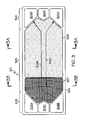
- FIG. 3 shows an alternate embodiment of the bipolar plate of FIG. 2 ;
- FIG. 3A shows a cross sectional view within the active region of the bipolar plate of FIG. 3 ;
- FIG. 3B shows a cross sectional view within the inactive region of the bipolar plate of FIG. 3 ;
- FIG. 4A shows a flow diagram of the cooperation between the water vapor transfer unit and at least one of the reactant flowpaths in the fuel cell of FIG. 2 ;
- FIG. 4B shows the water vapor transfer unit of FIG. 4A in more detail
- FIG. 5 shows a vehicle employing the fuel cell system of the present invention.
- FIGS. 1 and 5 a block diagram highlights the major components of a mobile fuel cell system 1 according to the present invention ( FIG. 1 ), as well as a representative placement of a fuel cell system into an automotive application ( FIG. 5 ).
- the system 1 includes a reactant delivery system 100 (made up of fuel source 100 A, oxygen source 100 B and one or more compressors 100 C), fuel processing system 200 , fuel cell 300 , one or more energy storage devices 400 , a drivetrain 500 and one or more motive devices 600 , shown notionally as a wheel.
- Fuel cell 300 includes an anode 310 , cathode 330 , and an electrolyte layer 320 disposed between anode 310 and cathode 330 . It will be appreciated by those skilled in the art that not every system may require a compressor. For example, in configurations where one or both of the fuel or oxygen sources 100 A, 100 B are supplied via pressurized tank or related container, such compressors may be dispensed with. While the present system 1 is shown for mobile (such as vehicular) applications, it will be appreciated by those skilled in the art that the use of the fuel cell 300 and its ancillary equipment is equally applicable to stationary applications. Although only a single fuel cell 300 is shown in FIG. 1 , it will be appreciated by those skilled in the art that fuel cell system 1 may be made from a stack of such cells serially connected. Referring with particularity to FIG. 5 , the use of such a stack 3000 is especially relevant to vehicular and related applications.
- the fuel processing system 200 may be incorporated to convert a raw fuel, such as methanol into hydrogen or hydrogen-rich fuel for use in fuel cell 300 ; otherwise, in configurations where the fuel source 100 A is already supplying substantially pure hydrogen, the fuel processing system 200 may not be required.
- the energy storage devices 400 can be in the form of one or more batteries, capacitors, electricity converters, or even a motor to convert the electric current coming from the fuel cell 300 into mechanical power such as rotating shaft power that can be used to operate drivetrain 500 and one or more motive devices 600 .
- FIG. 2 various features of a cathode side of a bipolar plate (also referred to simply as “plate”) 301 with a partial view of the various flow channels that make up flowpath 305 formed therein is shown.
- the present view depicts the side of the bipolar plate 301 that faces the cathode 330 (not presently shown), although it will be appreciated that the opposing side of the plate 301 is equally applicable to the discussion of how the present invention operates.
- the term “flow channel” is used generally to encompass the various forms of flow channels that make up flowpath 305 , including anode flow channels 305 A, cathode flow channels 305 B and optional coolant flow channels 305 C.
- cathode flow channels 305 B a partial view of cathode flow channels 305 B is shown.
- individual MEAs (not shown) are overlaid on the bipolar plate 301 such that the flow channels formed between the plate 301 and the respective anode or cathode diffusion media facilitate the flow of a corresponding reactant.
- the flowpath details of the plate 301 are for the cathode side of an otherwise conventional fuel cell, such configuration would be equally applicable to an anode (not presently shown).
- the diffusion media of cathode 330 mates with one surface of plate 301
- the diffusion media of the anode 310 mates with the other opposing surface.
- a frame 302 is used to define the outer boundaries of the plate 301 , and may include an upstanding lip or flange to increase plate sealing, rigidity or the like.
- the flow headers 303 , 304 formed within the frame 302 surround on opposing side edges a flowpath 305 disposed between them.
- the headers 303 , 304 define flow apertures therein to allow delivery of the appropriate reactants to their corresponding electrode within the bipolar plate, as well as an entire stack of plates when stacked together. Since the preferred direction of fluid movement in the anode and cathode flowpaths in plate 301 is counterflow, header 303 includes a cathode inlet manifold 303 B and an anode outlet manifold 303 A.
- header 304 includes a cathode outlet manifold 304 B and an anode inlet manifold 304 A.
- Coolant manifold 304 C is fluidly coupled to coolant manifold 303 C through a coolant flowpath (not shown) that extends from one header to the other.
- an anode flowpath (not shown, but which may be made up of numerous individual flow channels placed side-by-side in a fashion known to those skilled in the art and similar to that shown for cathode flow channels 305 B) extends between the two anode manifolds 303 A, 304 A to establish a flowpath for the hydrogen-bearing fluid.
- the flowpath 305 includes an active region 306 and inactive regions (also referred to as the humidifier regions) 307 that together define a fluidly continuous conduit, piping or related flow channel through which the oxygen-bearing reactant passes.
- the active region 306 may include various bends, curves or related serpentine patterns formed by the individual flow channels, as is known in the art, as a way to increase flowpath length and related contact area.
- the active region 306 is that portion of the flowpath 305 that would be overlaid with a diffusion media (which in turn is preferably overlaid with a catalyst) such that the electrochemical combination of the reactants produces electron flow, heat and water vapor.
- the inactive region 307 is that portion of the flowpath 305 that does not include catalyst, but is instead used to provide water transfer capability between moisture-rich and moisture-deficient flowpaths.
- the inactive region 307 does nothing to contribute to the generation of electricity through an electrochemical reaction.
- the cathode 330 is referred to as the “wet” end of fuel cell 300
- the anode 310 is referred to as the “dry” end. Consequently, the fluid flowing at the wet end has, in addition to oxygen, an elevated moisture content (for example, in the form of humidity), making it a moisture-rich fluid.
- FIGS. 3 , 3 A and 3 B an alternate configuration of bipolar plate 301 , showing how the inactive region 307 of flowpath 305 can be situated on one side of the cell such that it is adjacent one, rather than both, of the flow headers 303 , 304 .
- the drawing shows an individual cathode flow channel 305 B for the oxygen-bearing fluid that passes through cathode 330 , as well as a dotted line to represent (on the other side of plate 301 ) the flow on an individual anode channel 305 A of hydrogen-bearing fluid that starts at the anode inlet 304 A in flow header 304 and extends to anode outlet 303 A in flow header 303 .
- FIGS. 3A and 3B which are taken along various station lines of FIG. 3 , cross sectional views showing the stacked nature of the bipolar plate 301 and the anode 310 , cathode 330 and electrolyte (i.e., membrane) 320 shows the cooperation of the various flowpaths 305 A, 305 B and 305 C.
- FIG. 3A which corresponds to the portion of the bipolar plate 301 that defines the active region 306 , electrochemical reactions take place between the anode 310 , cathode 330 and the electrolyte 320 , as is well understood in the art.
- FIG. 3B is generally similar to FIG.
- the electrolyte 320 is replaced by a water transport unit 900 (discussed in more detail below).
- humidification takes place across the anode diffusion media.
- This media may include a hydrophilic layer, coating or construction to promote wicking or other humidification-enhancing behavior to the cathode inlet stream (described generally as a moisture-accepting fluid channel 920 below) using anode exhaust (described generally as a moisture-donating fluid channel 910 below).
- a recycle loop in the anode flowpath as such a recirculation loop increases the humidity of the fluid flowing through the anode.
- FIG. 4A a simplified block diagram depicting the formation of a water transport unit 900 into a fuel cell 300 and its bipolar plate 301 is shown.
- a humidification device would be placed away from the individual cells or the bipolar plates between individual MEAs
- the juxtaposition of the water transport unit 900 and each fuel cell 300 and its companion bipolar plate 301 indicates the high degree on integration and concomitant space-saving.
- the present figure illustrates the humidification of a cathode stream 3300 in a fuel cell stack 3000 . This embodiment is preferable when an anode stream 3100 is recycled using a pump 1000 or related device.
- water transport unit also referred to as a water vapor transfer unit or water transport unit
- the device 900 includes a moisture-donating fluid channel 910 , a moisture-accepting fluid channel 920 , a water transfer membrane 930 with first and second surfaces 930 A and 930 B and a diffusion media 940 .
- the first surface 930 A is exposed to the moisture-donating fluid, while the second surface 930 B is exposed to the moisture-accepting fluid.
- the first surface 930 A becomes the hydrophilic diffusion media, where it is inherently hydrophilic throughout it thickness by virtue of material properties or treatments.
- the anode flowpath that is the moisture-donating fluid channel 910 that is adjacent the first surface 930 A.
- the portion of diffusion media 940 on the moisture-accepting fluid channel 920 does not need to be hydrophilic.
- the hydrophilic diffusion media 940 on the moisture-donating side serves two beneficial functions. First, it pulls liquid water from the flow channels, keeping them free from blockage. Second, by holding liquid water against the water transfer membrane 930 it provides a more consistent supply of water to the moisture-accepting fluid channel 920 , thereby acting as a water buffer.
- the buffer action can ensure more consistent humidification of fuel cell 300 , as the tendency of the hydrophilic diffusion media 940 to store liquid water keeps the membrane 930 hydrated under fuel cell 300 operating conditions where periodic discharges of water may occur.
- some membrane materials show higher performance when liquid water is in contact with the side of the membrane 930 that faces (i.e., is adjacent) the moisture-donating fluid channel 910 . While the water transport unit 900 works with a moisture-donating fluid in either the liquid or vapor form, membrane 930 generally works better when the water contained in the fluid is in liquid form.
- the flexible porous construction of the hydrophilic diffusion media 940 is such that any water trapped in the moisture-donating fluid channel 910 of water transport unit 900 will wick to the layer during freeze conditions, which makes it resistant to freeze-thaw cycles.
- the two channels are in a counterflow relationship with one another such that the fluid in moisture-accepting fluid channel 920 enters the left side as shown with little or no humidity, and leaves on the right side with an increased level of humidity after having accepted water from the right-to-left flowing fluid in moisture-donating fluid channel 910 .
- the water transport unit 900 is shown as a pair of generally rectangular film-like channels 910 and 920 with membrane 930 and diffusion media 940 , it will be appreciated that the channels, membrane and diffusion media may be any of a variety of shapes. It will also be appreciated that the view shown in FIG. 4B is not to scale, and that spacing between the various elements therein are considerably smaller than indicated.
Landscapes
- Life Sciences & Earth Sciences (AREA)
- Engineering & Computer Science (AREA)
- Manufacturing & Machinery (AREA)
- Sustainable Development (AREA)
- Sustainable Energy (AREA)
- Chemical & Material Sciences (AREA)
- Chemical Kinetics & Catalysis (AREA)
- Electrochemistry (AREA)
- General Chemical & Material Sciences (AREA)
- Fuel Cell (AREA)
Abstract
Description
Claims (12)
Priority Applications (4)
| Application Number | Priority Date | Filing Date | Title |
|---|---|---|---|
| US11/358,356 US8101320B2 (en) | 2006-02-21 | 2006-02-21 | Fuel cell integrated humidification |
| JP2007039172A JP2007227377A (en) | 2006-02-21 | 2007-02-20 | Fuel cell integrated humidification |
| DE102007008214.4A DE102007008214B4 (en) | 2006-02-21 | 2007-02-20 | Fuel cell arrangement with integrated humidification |
| CNB2007100059999A CN100521339C (en) | 2006-02-21 | 2007-02-25 | Fuel cell component, operating method thereof and flow field for the fuel cell component |
Applications Claiming Priority (1)
| Application Number | Priority Date | Filing Date | Title |
|---|---|---|---|
| US11/358,356 US8101320B2 (en) | 2006-02-21 | 2006-02-21 | Fuel cell integrated humidification |
Publications (2)
| Publication Number | Publication Date |
|---|---|
| US20070196720A1 US20070196720A1 (en) | 2007-08-23 |
| US8101320B2 true US8101320B2 (en) | 2012-01-24 |
Family
ID=38289037
Family Applications (1)
| Application Number | Title | Priority Date | Filing Date |
|---|---|---|---|
| US11/358,356 Active 2029-05-08 US8101320B2 (en) | 2006-02-21 | 2006-02-21 | Fuel cell integrated humidification |
Country Status (4)
| Country | Link |
|---|---|
| US (1) | US8101320B2 (en) |
| JP (1) | JP2007227377A (en) |
| CN (1) | CN100521339C (en) |
| DE (1) | DE102007008214B4 (en) |
Cited By (2)
| Publication number | Priority date | Publication date | Assignee | Title |
|---|---|---|---|---|
| US9116451B2 (en) | 2011-02-24 | 2015-08-25 | Hewlett-Packard Development Company, L.P. | Coating for extending lifetime of an organic photoconductor |
| US10431844B2 (en) | 2015-01-29 | 2019-10-01 | Volkswagen Ag | Method for producing a catalytically coated membrane and membrane electrode assembly and fuel cell stack having same |
Families Citing this family (27)
| Publication number | Priority date | Publication date | Assignee | Title |
|---|---|---|---|---|
| JP5100640B2 (en) * | 2006-04-24 | 2012-12-19 | パナソニック株式会社 | MEA member and polymer electrolyte fuel cell |
| US20090202870A1 (en) * | 2006-05-30 | 2009-08-13 | Darling Robert M | Fuel Cell Employing Hydrated Non-Perfluorinated Hydrocarbon Ion Exchange Membrane |
| US8034502B2 (en) | 2007-04-02 | 2011-10-11 | GM Global Technology Operations LLC | Water removal system for non-reactive regions in PEFMC stacks |
| US8394547B2 (en) * | 2007-09-07 | 2013-03-12 | GM Global Technology Operations LLC | Fuel cell bipolar plate exit for improved flow distribution and freeze compatibility |
| US8051992B2 (en) * | 2008-01-25 | 2011-11-08 | GM Global Technology Operations LLC | Water transfer device employing a water buffer to increase water flux |
| JP4665978B2 (en) * | 2008-03-10 | 2011-04-06 | トヨタ自動車株式会社 | Fuel cell and fuel cell system |
| DE102008040208A1 (en) * | 2008-07-07 | 2010-01-14 | Robert Bosch Gmbh | Fuel cell i.e. polymer-electrolyte-membrane fuel cell, system for use in automotive field to produce current, has balancing areas arranged at end sides of membrane element for humidifying and tempering inflow streams |
| US8058352B2 (en) * | 2009-08-28 | 2011-11-15 | GM Global Technology Operations LLC | Perfluorocyclobutane based water vapor transfer membranes |
| US8354201B2 (en) * | 2009-08-28 | 2013-01-15 | GM Global Technology Operations LLC | Fuel cell with spatially non-homogeneous ionic membrane |
| US7972732B2 (en) * | 2009-08-28 | 2011-07-05 | GM Global Technology Operations LLC | Perfluorocyclobutane based water vapor transfer membranes with side chain perfluorosulfonic acid moieties |
| US20110053008A1 (en) * | 2009-08-28 | 2011-03-03 | Gm Global Technology Operations, Inc. | Water vapor transfer membrane and paper integrated assembly |
| US20110053009A1 (en) * | 2009-08-28 | 2011-03-03 | Gm Global Technology Operations, Inc. | Customized water vapor transfer membrane layered structure |
| JP2012142135A (en) * | 2010-12-28 | 2012-07-26 | Toyota Motor Corp | Fuel cell |
| DE102012011441A1 (en) | 2011-07-02 | 2013-01-03 | Volkswagen Aktiengesellschaft | Membrane electrode unit for a fuel cell |
| TWI474548B (en) * | 2011-09-05 | 2015-02-21 | Asia Pacific Fuel Cell Tech | Polar plate and polar plate unit using the same |
| CN103247807B (en) * | 2012-02-08 | 2015-07-08 | 武汉众宇动力系统科技有限公司 | Proton exchange membrane fuel cell based on phase-change heat transfer and bipolar plate thereof |
| DE102012012257A1 (en) * | 2012-06-22 | 2013-12-24 | Daimler Ag | Separator plate for fuel cell of fuel cell system, has heat-exchange area for cooling operating medium to be humidified that is arranged in upstream of humidification region |
| CN102800876A (en) * | 2012-09-06 | 2012-11-28 | 江苏冰城电材股份有限公司 | Self-humidifying fuel cell |
| DE102013210542A1 (en) | 2013-06-06 | 2014-12-11 | Volkswagen Ag | Bipolar plate, fuel cell with such and motor vehicle with such a fuel cell |
| DE102014219164A1 (en) | 2014-09-23 | 2016-03-24 | Volkswagen Aktiengesellschaft | Fuel cell stack with integrated humidifier and vehicle with such |
| DE102015201113A1 (en) | 2015-01-23 | 2016-07-28 | Volkswagen Ag | Bipolar plate and fuel cell with such a |
| DE102015225228A1 (en) | 2015-11-24 | 2017-05-24 | Volkswagen Aktiengesellschaft | Bipolar plate for a fuel cell and fuel cell stack with such |
| DE202016105309U1 (en) * | 2016-09-23 | 2018-01-09 | Reinz-Dichtungs-Gmbh | humidifier |
| DE102019212086A1 (en) * | 2019-08-13 | 2021-02-18 | Audi Ag | Fuel cell device |
| DE102019126301A1 (en) * | 2019-09-30 | 2021-04-01 | Audi Ag | Humidifier and fuel cell device with humidifier |
| DE102020005246A1 (en) | 2020-08-27 | 2022-03-03 | Cellcentric Gmbh & Co. Kg | fuel cell stack |
| DE102021119655B4 (en) | 2021-07-28 | 2025-11-13 | Audi Aktiengesellschaft | Membrane electrode assembly, fuel cell stack, fuel cell device and motor vehicle with such a |
Citations (13)
| Publication number | Priority date | Publication date | Assignee | Title |
|---|---|---|---|---|
| US4175165A (en) | 1977-07-20 | 1979-11-20 | Engelhard Minerals & Chemicals Corporation | Fuel cell system utilizing ion exchange membranes and bipolar plates |
| US4769297A (en) | 1987-11-16 | 1988-09-06 | International Fuel Cells Corporation | Solid polymer electrolyte fuel cell stack water management system |
| US4973530A (en) | 1989-12-21 | 1990-11-27 | The United States Of America As Represented By The United States Department Of Energy | Fuel cell water transport |
| US5543238A (en) | 1992-08-10 | 1996-08-06 | Siemens Aktiengesellschaft | Fuel cell and method for moistening the electrolyte of the fuel cell |
| US6451466B1 (en) | 2000-04-06 | 2002-09-17 | Utc Fuel Cells, Llc | Functional integration of multiple components for a fuel cell power plant |
| US6471195B2 (en) | 2000-01-19 | 2002-10-29 | Honda Giken Kogyo Kabushiki Kaisha | Humidifier for use with a fuel cell |
| US6630260B2 (en) | 2001-07-20 | 2003-10-07 | General Motors Corporation | Water vapor transfer device for a fuel cell power plant |
| US20040137298A1 (en) * | 2001-03-06 | 2004-07-15 | Seiji Sugiura | Solid polymer electrolyte fuel cell assmebly with gas passages in serial communication , and method of supplying reaction gas in fuel cell |
| US6821661B2 (en) * | 2001-08-31 | 2004-11-23 | Plug Power, Inc. | Hydrophilic anode gas diffusion layer |
| US20040241020A1 (en) * | 2003-05-27 | 2004-12-02 | Ralph Hobmeyr | Fluid handling device for hydrogen-containing process fluids |
| JP2005267958A (en) | 2004-03-17 | 2005-09-29 | Matsushita Electric Ind Co Ltd | Polymer electrolyte fuel cell |
| US20060008695A1 (en) * | 2004-07-09 | 2006-01-12 | Dingrong Bai | Fuel cell with in-cell humidification |
| US20060134487A1 (en) * | 2004-12-17 | 2006-06-22 | Chao-Yang Wang | Methods to control water flow and distribution in direct methanol fuel cells |
Family Cites Families (3)
| Publication number | Priority date | Publication date | Assignee | Title |
|---|---|---|---|---|
| US5284718A (en) * | 1991-09-27 | 1994-02-08 | Ballard Power Systems Inc. | Fuel cell membrane electrode and seal assembly |
| JPH11354142A (en) * | 1998-06-11 | 1999-12-24 | Toshiba Corp | Solid polymer electrolyte fuel cell |
| JP2003031244A (en) * | 2001-07-13 | 2003-01-31 | Honda Motor Co Ltd | Gas circulation system for fuel cell and gas circulation device for fuel cell |
-
2006
- 2006-02-21 US US11/358,356 patent/US8101320B2/en active Active
-
2007
- 2007-02-20 DE DE102007008214.4A patent/DE102007008214B4/en active Active
- 2007-02-20 JP JP2007039172A patent/JP2007227377A/en active Pending
- 2007-02-25 CN CNB2007100059999A patent/CN100521339C/en active Active
Patent Citations (13)
| Publication number | Priority date | Publication date | Assignee | Title |
|---|---|---|---|---|
| US4175165A (en) | 1977-07-20 | 1979-11-20 | Engelhard Minerals & Chemicals Corporation | Fuel cell system utilizing ion exchange membranes and bipolar plates |
| US4769297A (en) | 1987-11-16 | 1988-09-06 | International Fuel Cells Corporation | Solid polymer electrolyte fuel cell stack water management system |
| US4973530A (en) | 1989-12-21 | 1990-11-27 | The United States Of America As Represented By The United States Department Of Energy | Fuel cell water transport |
| US5543238A (en) | 1992-08-10 | 1996-08-06 | Siemens Aktiengesellschaft | Fuel cell and method for moistening the electrolyte of the fuel cell |
| US6471195B2 (en) | 2000-01-19 | 2002-10-29 | Honda Giken Kogyo Kabushiki Kaisha | Humidifier for use with a fuel cell |
| US6451466B1 (en) | 2000-04-06 | 2002-09-17 | Utc Fuel Cells, Llc | Functional integration of multiple components for a fuel cell power plant |
| US20040137298A1 (en) * | 2001-03-06 | 2004-07-15 | Seiji Sugiura | Solid polymer electrolyte fuel cell assmebly with gas passages in serial communication , and method of supplying reaction gas in fuel cell |
| US6630260B2 (en) | 2001-07-20 | 2003-10-07 | General Motors Corporation | Water vapor transfer device for a fuel cell power plant |
| US6821661B2 (en) * | 2001-08-31 | 2004-11-23 | Plug Power, Inc. | Hydrophilic anode gas diffusion layer |
| US20040241020A1 (en) * | 2003-05-27 | 2004-12-02 | Ralph Hobmeyr | Fluid handling device for hydrogen-containing process fluids |
| JP2005267958A (en) | 2004-03-17 | 2005-09-29 | Matsushita Electric Ind Co Ltd | Polymer electrolyte fuel cell |
| US20060008695A1 (en) * | 2004-07-09 | 2006-01-12 | Dingrong Bai | Fuel cell with in-cell humidification |
| US20060134487A1 (en) * | 2004-12-17 | 2006-06-22 | Chao-Yang Wang | Methods to control water flow and distribution in direct methanol fuel cells |
Cited By (2)
| Publication number | Priority date | Publication date | Assignee | Title |
|---|---|---|---|---|
| US9116451B2 (en) | 2011-02-24 | 2015-08-25 | Hewlett-Packard Development Company, L.P. | Coating for extending lifetime of an organic photoconductor |
| US10431844B2 (en) | 2015-01-29 | 2019-10-01 | Volkswagen Ag | Method for producing a catalytically coated membrane and membrane electrode assembly and fuel cell stack having same |
Also Published As
| Publication number | Publication date |
|---|---|
| DE102007008214B4 (en) | 2018-02-22 |
| DE102007008214A1 (en) | 2007-08-23 |
| US20070196720A1 (en) | 2007-08-23 |
| CN101026243A (en) | 2007-08-29 |
| CN100521339C (en) | 2009-07-29 |
| JP2007227377A (en) | 2007-09-06 |
Similar Documents
| Publication | Publication Date | Title |
|---|---|---|
| US8101320B2 (en) | Fuel cell integrated humidification | |
| US9905880B2 (en) | Fuel cell stack | |
| US7718298B2 (en) | Bifurcation of flow channels in bipolar plate flowfields | |
| US8003278B2 (en) | Fuel cell | |
| EP1517392A1 (en) | Solid high polymer type cell assembly | |
| US7258329B2 (en) | Reactant gas humidification apparatus and reactant gas humidification method | |
| US10637077B2 (en) | Frame equipped membrane electrode assembly and fuel cell | |
| JP2020013742A (en) | Power generation cell | |
| CN102593485B (en) | Fuel cell | |
| US12362370B2 (en) | Humidifier for fuel cell | |
| JP7689775B2 (en) | Four-fluid bipolar plate for fuel cells | |
| US11777110B2 (en) | Fuel cell | |
| US9793568B2 (en) | Solid polymer electrolyte fuel cell | |
| US12046781B2 (en) | Compression apparatus | |
| CN102714321B (en) | Fuel cell and vehicle equipped with fuel cell | |
| CN102130353B (en) | Solid high-polymer fuel cell | |
| JP3963716B2 (en) | Fuel cell stack | |
| KR20090068262A (en) | Fuel cell | |
| KR20080051355A (en) | Separator for Fuel Cell | |
| JP7813837B2 (en) | fuel cell stack | |
| JP7634028B2 (en) | Power generation cells and fuel cell stacks | |
| JP2021170484A (en) | Fuel cell system | |
| US20080096081A1 (en) | Fuel Cell | |
| JP2009135062A (en) | Fuel cell stack |
Legal Events
| Date | Code | Title | Description |
|---|---|---|---|
| AS | Assignment |
Owner name: GM GLOBAL TECHNOLOGY OPERATIONS, INC., MICHIGAN Free format text: ASSIGNMENT OF ASSIGNORS INTEREST;ASSIGNOR:SKALA, GLENN W.;REEL/FRAME:017428/0630 Effective date: 20060210 |
|
| AS | Assignment |
Owner name: UNITED STATES DEPARTMENT OF THE TREASURY, DISTRICT Free format text: SECURITY AGREEMENT;ASSIGNOR:GM GLOBAL TECHNOLOGY OPERATIONS, INC.;REEL/FRAME:022195/0334 Effective date: 20081231 Owner name: UNITED STATES DEPARTMENT OF THE TREASURY,DISTRICT Free format text: SECURITY AGREEMENT;ASSIGNOR:GM GLOBAL TECHNOLOGY OPERATIONS, INC.;REEL/FRAME:022195/0334 Effective date: 20081231 |
|
| AS | Assignment |
Owner name: CITICORP USA, INC. AS AGENT FOR BANK PRIORITY SECU Free format text: SECURITY AGREEMENT;ASSIGNOR:GM GLOBAL TECHNOLOGY OPERATIONS, INC.;REEL/FRAME:022553/0493 Effective date: 20090409 Owner name: CITICORP USA, INC. AS AGENT FOR HEDGE PRIORITY SEC Free format text: SECURITY AGREEMENT;ASSIGNOR:GM GLOBAL TECHNOLOGY OPERATIONS, INC.;REEL/FRAME:022553/0493 Effective date: 20090409 |
|
| AS | Assignment |
Owner name: GM GLOBAL TECHNOLOGY OPERATIONS, INC., MICHIGAN Free format text: RELEASE BY SECURED PARTY;ASSIGNOR:UNITED STATES DEPARTMENT OF THE TREASURY;REEL/FRAME:023124/0519 Effective date: 20090709 Owner name: GM GLOBAL TECHNOLOGY OPERATIONS, INC.,MICHIGAN Free format text: RELEASE BY SECURED PARTY;ASSIGNOR:UNITED STATES DEPARTMENT OF THE TREASURY;REEL/FRAME:023124/0519 Effective date: 20090709 |
|
| AS | Assignment |
Owner name: GM GLOBAL TECHNOLOGY OPERATIONS, INC., MICHIGAN Free format text: RELEASE BY SECURED PARTY;ASSIGNORS:CITICORP USA, INC. AS AGENT FOR BANK PRIORITY SECURED PARTIES;CITICORP USA, INC. AS AGENT FOR HEDGE PRIORITY SECURED PARTIES;REEL/FRAME:023127/0402 Effective date: 20090814 Owner name: GM GLOBAL TECHNOLOGY OPERATIONS, INC.,MICHIGAN Free format text: RELEASE BY SECURED PARTY;ASSIGNORS:CITICORP USA, INC. AS AGENT FOR BANK PRIORITY SECURED PARTIES;CITICORP USA, INC. AS AGENT FOR HEDGE PRIORITY SECURED PARTIES;REEL/FRAME:023127/0402 Effective date: 20090814 |
|
| AS | Assignment |
Owner name: UNITED STATES DEPARTMENT OF THE TREASURY, DISTRICT Free format text: SECURITY AGREEMENT;ASSIGNOR:GM GLOBAL TECHNOLOGY OPERATIONS, INC.;REEL/FRAME:023156/0142 Effective date: 20090710 Owner name: UNITED STATES DEPARTMENT OF THE TREASURY,DISTRICT Free format text: SECURITY AGREEMENT;ASSIGNOR:GM GLOBAL TECHNOLOGY OPERATIONS, INC.;REEL/FRAME:023156/0142 Effective date: 20090710 |
|
| AS | Assignment |
Owner name: UAW RETIREE MEDICAL BENEFITS TRUST, MICHIGAN Free format text: SECURITY AGREEMENT;ASSIGNOR:GM GLOBAL TECHNOLOGY OPERATIONS, INC.;REEL/FRAME:023162/0093 Effective date: 20090710 Owner name: UAW RETIREE MEDICAL BENEFITS TRUST,MICHIGAN Free format text: SECURITY AGREEMENT;ASSIGNOR:GM GLOBAL TECHNOLOGY OPERATIONS, INC.;REEL/FRAME:023162/0093 Effective date: 20090710 |
|
| FEPP | Fee payment procedure |
Free format text: PAYOR NUMBER ASSIGNED (ORIGINAL EVENT CODE: ASPN); ENTITY STATUS OF PATENT OWNER: LARGE ENTITY |
|
| AS | Assignment |
Owner name: GM GLOBAL TECHNOLOGY OPERATIONS, INC., MICHIGAN Free format text: RELEASE BY SECURED PARTY;ASSIGNOR:UNITED STATES DEPARTMENT OF THE TREASURY;REEL/FRAME:025245/0587 Effective date: 20100420 |
|
| AS | Assignment |
Owner name: GM GLOBAL TECHNOLOGY OPERATIONS, INC., MICHIGAN Free format text: RELEASE BY SECURED PARTY;ASSIGNOR:UAW RETIREE MEDICAL BENEFITS TRUST;REEL/FRAME:025314/0901 Effective date: 20101026 |
|
| AS | Assignment |
Owner name: WILMINGTON TRUST COMPANY, DELAWARE Free format text: SECURITY AGREEMENT;ASSIGNOR:GM GLOBAL TECHNOLOGY OPERATIONS, INC.;REEL/FRAME:025327/0041 Effective date: 20101027 |
|
| AS | Assignment |
Owner name: GM GLOBAL TECHNOLOGY OPERATIONS LLC, MICHIGAN Free format text: CHANGE OF NAME;ASSIGNOR:GM GLOBAL TECHNOLOGY OPERATIONS, INC.;REEL/FRAME:025781/0001 Effective date: 20101202 |
|
| STCF | Information on status: patent grant |
Free format text: PATENTED CASE |
|
| AS | Assignment |
Owner name: GM GLOBAL TECHNOLOGY OPERATIONS LLC, MICHIGAN Free format text: RELEASE BY SECURED PARTY;ASSIGNOR:WILMINGTON TRUST COMPANY;REEL/FRAME:034184/0001 Effective date: 20141017 |
|
| FPAY | Fee payment |
Year of fee payment: 4 |
|
| MAFP | Maintenance fee payment |
Free format text: PAYMENT OF MAINTENANCE FEE, 8TH YEAR, LARGE ENTITY (ORIGINAL EVENT CODE: M1552); ENTITY STATUS OF PATENT OWNER: LARGE ENTITY Year of fee payment: 8 |
|
| MAFP | Maintenance fee payment |
Free format text: PAYMENT OF MAINTENANCE FEE, 12TH YEAR, LARGE ENTITY (ORIGINAL EVENT CODE: M1553); ENTITY STATUS OF PATENT OWNER: LARGE ENTITY Year of fee payment: 12 |