JP7689775B2 - Four-fluid bipolar plate for fuel cells - Google Patents
Four-fluid bipolar plate for fuel cells Download PDFInfo
- Publication number
- JP7689775B2 JP7689775B2 JP2024187542A JP2024187542A JP7689775B2 JP 7689775 B2 JP7689775 B2 JP 7689775B2 JP 2024187542 A JP2024187542 A JP 2024187542A JP 2024187542 A JP2024187542 A JP 2024187542A JP 7689775 B2 JP7689775 B2 JP 7689775B2
- Authority
- JP
- Japan
- Prior art keywords
- porous
- water
- subplate
- bipolar plate
- flow field
- Prior art date
- Legal status (The legal status is an assumption and is not a legal conclusion. Google has not performed a legal analysis and makes no representation as to the accuracy of the status listed.)
- Active
Links
Images


Classifications
-
- H—ELECTRICITY
- H01—ELECTRIC ELEMENTS
- H01M—PROCESSES OR MEANS, e.g. BATTERIES, FOR THE DIRECT CONVERSION OF CHEMICAL ENERGY INTO ELECTRICAL ENERGY
- H01M8/00—Fuel cells; Manufacture thereof
- H01M8/04—Auxiliary arrangements, e.g. for control of pressure or for circulation of fluids
- H01M8/04082—Arrangements for control of reactant parameters, e.g. pressure or concentration
- H01M8/04089—Arrangements for control of reactant parameters, e.g. pressure or concentration of gaseous reactants
- H01M8/04119—Arrangements for control of reactant parameters, e.g. pressure or concentration of gaseous reactants with simultaneous supply or evacuation of electrolyte; Humidifying or dehumidifying
- H01M8/04126—Humidifying
- H01M8/04134—Humidifying by coolants
-
- H—ELECTRICITY
- H01—ELECTRIC ELEMENTS
- H01M—PROCESSES OR MEANS, e.g. BATTERIES, FOR THE DIRECT CONVERSION OF CHEMICAL ENERGY INTO ELECTRICAL ENERGY
- H01M8/00—Fuel cells; Manufacture thereof
- H01M8/02—Details
- H01M8/0202—Collectors; Separators, e.g. bipolar separators; Interconnectors
- H01M8/0204—Non-porous and characterised by the material
- H01M8/0206—Metals or alloys
-
- H—ELECTRICITY
- H01—ELECTRIC ELEMENTS
- H01M—PROCESSES OR MEANS, e.g. BATTERIES, FOR THE DIRECT CONVERSION OF CHEMICAL ENERGY INTO ELECTRICAL ENERGY
- H01M8/00—Fuel cells; Manufacture thereof
- H01M8/02—Details
- H01M8/0202—Collectors; Separators, e.g. bipolar separators; Interconnectors
- H01M8/023—Porous and characterised by the material
- H01M8/0234—Carbonaceous material
-
- H—ELECTRICITY
- H01—ELECTRIC ELEMENTS
- H01M—PROCESSES OR MEANS, e.g. BATTERIES, FOR THE DIRECT CONVERSION OF CHEMICAL ENERGY INTO ELECTRICAL ENERGY
- H01M8/00—Fuel cells; Manufacture thereof
- H01M8/02—Details
- H01M8/0202—Collectors; Separators, e.g. bipolar separators; Interconnectors
- H01M8/0258—Collectors; Separators, e.g. bipolar separators; Interconnectors characterised by the configuration of channels, e.g. by the flow field of the reactant or coolant
-
- H—ELECTRICITY
- H01—ELECTRIC ELEMENTS
- H01M—PROCESSES OR MEANS, e.g. BATTERIES, FOR THE DIRECT CONVERSION OF CHEMICAL ENERGY INTO ELECTRICAL ENERGY
- H01M8/00—Fuel cells; Manufacture thereof
- H01M8/02—Details
- H01M8/0202—Collectors; Separators, e.g. bipolar separators; Interconnectors
- H01M8/0267—Collectors; Separators, e.g. bipolar separators; Interconnectors having heating or cooling means, e.g. heaters or coolant flow channels
-
- H—ELECTRICITY
- H01—ELECTRIC ELEMENTS
- H01M—PROCESSES OR MEANS, e.g. BATTERIES, FOR THE DIRECT CONVERSION OF CHEMICAL ENERGY INTO ELECTRICAL ENERGY
- H01M8/00—Fuel cells; Manufacture thereof
- H01M8/02—Details
- H01M8/0271—Sealing or supporting means around electrodes, matrices or membranes
-
- H—ELECTRICITY
- H01—ELECTRIC ELEMENTS
- H01M—PROCESSES OR MEANS, e.g. BATTERIES, FOR THE DIRECT CONVERSION OF CHEMICAL ENERGY INTO ELECTRICAL ENERGY
- H01M8/00—Fuel cells; Manufacture thereof
- H01M8/04—Auxiliary arrangements, e.g. for control of pressure or for circulation of fluids
- H01M8/04007—Auxiliary arrangements, e.g. for control of pressure or for circulation of fluids related to heat exchange
- H01M8/04029—Heat exchange using liquids
-
- H—ELECTRICITY
- H01—ELECTRIC ELEMENTS
- H01M—PROCESSES OR MEANS, e.g. BATTERIES, FOR THE DIRECT CONVERSION OF CHEMICAL ENERGY INTO ELECTRICAL ENERGY
- H01M8/00—Fuel cells; Manufacture thereof
- H01M8/04—Auxiliary arrangements, e.g. for control of pressure or for circulation of fluids
- H01M8/04082—Arrangements for control of reactant parameters, e.g. pressure or concentration
- H01M8/04089—Arrangements for control of reactant parameters, e.g. pressure or concentration of gaseous reactants
- H01M8/04097—Arrangements for control of reactant parameters, e.g. pressure or concentration of gaseous reactants with recycling of the reactants
-
- H—ELECTRICITY
- H01—ELECTRIC ELEMENTS
- H01M—PROCESSES OR MEANS, e.g. BATTERIES, FOR THE DIRECT CONVERSION OF CHEMICAL ENERGY INTO ELECTRICAL ENERGY
- H01M8/00—Fuel cells; Manufacture thereof
- H01M8/04—Auxiliary arrangements, e.g. for control of pressure or for circulation of fluids
- H01M8/04082—Arrangements for control of reactant parameters, e.g. pressure or concentration
- H01M8/04089—Arrangements for control of reactant parameters, e.g. pressure or concentration of gaseous reactants
- H01M8/04119—Arrangements for control of reactant parameters, e.g. pressure or concentration of gaseous reactants with simultaneous supply or evacuation of electrolyte; Humidifying or dehumidifying
- H01M8/04126—Humidifying
-
- H—ELECTRICITY
- H01—ELECTRIC ELEMENTS
- H01M—PROCESSES OR MEANS, e.g. BATTERIES, FOR THE DIRECT CONVERSION OF CHEMICAL ENERGY INTO ELECTRICAL ENERGY
- H01M8/00—Fuel cells; Manufacture thereof
- H01M8/04—Auxiliary arrangements, e.g. for control of pressure or for circulation of fluids
- H01M8/04082—Arrangements for control of reactant parameters, e.g. pressure or concentration
- H01M8/04089—Arrangements for control of reactant parameters, e.g. pressure or concentration of gaseous reactants
- H01M8/04119—Arrangements for control of reactant parameters, e.g. pressure or concentration of gaseous reactants with simultaneous supply or evacuation of electrolyte; Humidifying or dehumidifying
- H01M8/04156—Arrangements for control of reactant parameters, e.g. pressure or concentration of gaseous reactants with simultaneous supply or evacuation of electrolyte; Humidifying or dehumidifying with product water removal
-
- H—ELECTRICITY
- H01—ELECTRIC ELEMENTS
- H01M—PROCESSES OR MEANS, e.g. BATTERIES, FOR THE DIRECT CONVERSION OF CHEMICAL ENERGY INTO ELECTRICAL ENERGY
- H01M8/00—Fuel cells; Manufacture thereof
- H01M8/04—Auxiliary arrangements, e.g. for control of pressure or for circulation of fluids
- H01M8/04291—Arrangements for managing water in solid electrolyte fuel cell systems
-
- H—ELECTRICITY
- H01—ELECTRIC ELEMENTS
- H01M—PROCESSES OR MEANS, e.g. BATTERIES, FOR THE DIRECT CONVERSION OF CHEMICAL ENERGY INTO ELECTRICAL ENERGY
- H01M8/00—Fuel cells; Manufacture thereof
- H01M8/10—Fuel cells with solid electrolytes
- H01M8/1004—Fuel cells with solid electrolytes characterised by membrane-electrode assemblies [MEA]
-
- B—PERFORMING OPERATIONS; TRANSPORTING
- B01—PHYSICAL OR CHEMICAL PROCESSES OR APPARATUS IN GENERAL
- B01D—SEPARATION
- B01D2258/00—Sources of waste gases
- B01D2258/02—Other waste gases
- B01D2258/0208—Other waste gases from fuel cells
-
- H—ELECTRICITY
- H01—ELECTRIC ELEMENTS
- H01M—PROCESSES OR MEANS, e.g. BATTERIES, FOR THE DIRECT CONVERSION OF CHEMICAL ENERGY INTO ELECTRICAL ENERGY
- H01M8/00—Fuel cells; Manufacture thereof
- H01M8/10—Fuel cells with solid electrolytes
- H01M2008/1095—Fuel cells with polymeric electrolytes
-
- H—ELECTRICITY
- H01—ELECTRIC ELEMENTS
- H01M—PROCESSES OR MEANS, e.g. BATTERIES, FOR THE DIRECT CONVERSION OF CHEMICAL ENERGY INTO ELECTRICAL ENERGY
- H01M2250/00—Fuel cells for particular applications; Specific features of fuel cell system
- H01M2250/10—Fuel cells in stationary systems, e.g. emergency power source in plant
-
- Y—GENERAL TAGGING OF NEW TECHNOLOGICAL DEVELOPMENTS; GENERAL TAGGING OF CROSS-SECTIONAL TECHNOLOGIES SPANNING OVER SEVERAL SECTIONS OF THE IPC; TECHNICAL SUBJECTS COVERED BY FORMER USPC CROSS-REFERENCE ART COLLECTIONS [XRACs] AND DIGESTS
- Y02—TECHNOLOGIES OR APPLICATIONS FOR MITIGATION OR ADAPTATION AGAINST CLIMATE CHANGE
- Y02E—REDUCTION OF GREENHOUSE GAS [GHG] EMISSIONS, RELATED TO ENERGY GENERATION, TRANSMISSION OR DISTRIBUTION
- Y02E60/00—Enabling technologies; Technologies with a potential or indirect contribution to GHG emissions mitigation
- Y02E60/30—Hydrogen technology
- Y02E60/50—Fuel cells
Landscapes
- Life Sciences & Earth Sciences (AREA)
- Sustainable Development (AREA)
- Engineering & Computer Science (AREA)
- Manufacturing & Machinery (AREA)
- Sustainable Energy (AREA)
- Chemical & Material Sciences (AREA)
- Chemical Kinetics & Catalysis (AREA)
- Electrochemistry (AREA)
- General Chemical & Material Sciences (AREA)
- Fuel Cell (AREA)
Description
関連出願への相互参照
本出願は、2021年6月10日に出願された「FOUR-FLUID BIPOLAR PLATE FOR FUEL CELL(燃料電池用4流体バイポーラプレート)」のタイトルの米国特許出願第17/344,377号を参照し、該出願からの優先権およびその利益を主張するものであり、該出願は参照によりその全体が本明細書に組み込まれるものとする。
CROSS-REFERENCE TO RELATED APPLICATIONS This application references and claims priority to and the benefit of U.S. patent application Ser. No. 17/344,377, entitled "FOUR-FLUID BIPOLAR PLATE FOR FUEL CELL," filed June 10, 2021, which is incorporated herein by reference in its entirety.
本開示は概して、燃料電池バイポーラプレートに関し、より具体的には、加湿された反応物の改善されたデリバリー、および、生成水のより良好な除去を提供するバイポーラプレート構造に関する。 The present disclosure relates generally to fuel cell bipolar plates, and more specifically to a bipolar plate structure that provides improved delivery of humidified reactants and better removal of product water.
プロトン交換膜(PEM)燃料電池では、水素燃料が負極(アノード)に供給され、そこで酸化反応 H2→2H++2e-によりプロトンと電子に触媒的に解離される。プロトン(H+)は膜電解質を通り正極(カソード)に到達するが、電子(e-)は外部経路を通って伝導され、外部負荷を介してアノードとカソードの間に電流が生成される。カソードでは、還元反応:O2+4e-+4H+→2H2Oに従って、プロトンと電子が酸素の存在下で再結合し、水を形成する。PEM燃料電池反応の副生成物は水と熱であり、該熱は、許容可能な内部温度を維持するために燃料電池を冷却することを必要とする。 In a proton exchange membrane (PEM) fuel cell, hydrogen fuel is fed to the negative electrode (anode) where it is catalytically dissociated into protons and electrons via the oxidation reaction H 2 →2H ++ 2e-. The protons (H + ) pass through the membrane electrolyte to reach the positive electrode (cathode), while the electrons ( e- ) are conducted through an external pathway to generate an electric current between the anode and cathode through an external load. At the cathode, the protons and electrons recombine in the presence of oxygen to form water according to the reduction reaction: O 2 + 4e- +4H + →2H 2 O. By-products of the PEM fuel cell reaction are water and heat, which necessitates cooling the fuel cell to maintain an acceptable internal temperature.
単一の燃料電池は、一対の電極(アノードおよびカソード)の間に挟まれた膜電解質を含む膜電極接合体(MEA)と、膜電解質とは反対側で各電極に隣接する、反応ガスフローフィールドを画定する導電性プレートとを含む。典型的なフローフィールドプレートは、反応ガスをガス拡散層と微多孔質層を通ってそれぞれの電極に導く。一部の設計では、フローフィールドプレートは水副生成物をセルから運び出すこともできる。 A single fuel cell includes a membrane electrode assembly (MEA) that contains a membrane electrolyte sandwiched between a pair of electrodes (anode and cathode), and conductive plates adjacent to each electrode on the opposite side from the membrane electrolyte that define a reactant gas flow field. A typical flow field plate directs the reactant gases through gas diffusion layers and microporous layers to their respective electrodes. In some designs, the flow field plate can also carry the water by-product out of the cell.
電気化学変換アセンブリまたは燃料電池の電気出力を高めるために、複数の燃料電池が、一般的に、スタックで連続して配置および接続される。この配置において、2つの隣接するセルユニットは、共通のポーラプレートを共有することができ、これは、直列に接続された2つの隣接するセルユニットのアノードおよびカソードとして機能する。このようなポーラプレートは一般に、「バイポーラプレート」と称される。 To increase the electrical output of an electrochemical conversion assembly or fuel cell, multiple fuel cells are typically arranged and connected in series in a stack. In this arrangement, two adjacent cell units can share a common polar plate, which serves as the anode and cathode for the two adjacent cell units connected in series. Such a polar plate is commonly referred to as a "bipolar plate."
一実施形態では、燃料電池用バイポーラプレートは、少なくとも1つの水管理面と内部冷却剤通路とを含む非多孔質サブプレートを含む。バイポーラプレートは、反応物面と、反対側の水管理面とを含む、多孔質サブプレートをさらに含む。多孔質サブプレートの反応物面は、第1反応物フローフィールドを含み、水管理面は、非多孔質サブプレートの水管理面に流体接続される。 In one embodiment, a bipolar plate for a fuel cell includes a non-porous subplate including at least one water management surface and an internal coolant passage. The bipolar plate further includes a porous subplate including a reactant surface and an opposing water management surface. The reactant surface of the porous subplate includes a first reactant flow field, and the water management surface is fluidly connected to the water management surface of the non-porous subplate.
別の実施形態では、燃料電池用バイポーラプレートは、酸化剤フローフィールド、燃料反応物フローフィールド、専用冷却剤通路、および水管理フローフィールドを含む。 In another embodiment, a bipolar plate for a fuel cell includes an oxidant flow field, a fuel reactant flow field, dedicated coolant passages, and a water management flow field.
さらに別の実施形態では、燃料電池用バイポーラプレートは、水管理面と反応物面とを備える非多孔質サブプレートを含む。該反応物面は、第1反応物フローフィールドを含む。バイポーラプレートは、反応物面と、反対側の水管理面とを備える多孔質サブプレートをさらに含む。該反応物面は、第2反応物フローフィールドを含む。多孔質サブプレートの水管理面は、非多孔質サブプレートの水管理面に流体接続されている。 In yet another embodiment, a bipolar plate for a fuel cell includes a non-porous subplate having a water management surface and a reactant surface. The reactant surface includes a first reactant flow field. The bipolar plate further includes a porous subplate having a reactant surface and an opposing water management surface. The reactant surface includes a second reactant flow field. The water management surface of the porous subplate is fluidly connected to the water management surface of the non-porous subplate.
本明細書で説明する特徴は、以下に説明する図面を参照するとよりよく理解できる。図面は必ずしも縮尺通りではなく、該して本発明の原理を説明することに重点が置かれている。図面では、様々な図を通して同様の部分を示すために同様の番号が使用されている。 The features described herein can be better understood with reference to the drawings described below. The drawings are not necessarily to scale, with emphasis generally being placed upon illustrating the principles of the invention. In the drawings, like numbers are used to denote like parts throughout the various views.
図1には、典型的な高分子電解質膜(PEM)燃料電池10が示され、これは一般に、アイオノマー膜16によって分離された負極(アノード)12および正極(カソード)14を含む。アノード触媒層18aおよびカソード触媒層18cは、該して平面の膜のそれぞれの面に形成され、水素および酸素反応ガスを電気と水に変換する。この接合体は通常、膜電極接合体(MEA)20と称される。触媒層18a、18cは、アノード12およびカソード14について同一であってよいが、通常これらは異なる。例えば、アノード触媒層18aは、水素原子を水素イオンおよび電子に分ける機能を有してよく、一方、カソード触媒層18cは、酸素ガスと電子を反応させ水を形成する機能を有し得る。
1 shows a typical polymer electrolyte membrane (PEM)
反応物(すなわち、水素および空気)は、典型的には反応物フローチャネル(破線で示す)を含むフローフィールドプレート22によって、MEA20に導かれる。フローフィールドプレート22は、バイポーラプレートとして示され、燃料と酸化剤の両方のための反応物フローチャネルを含む。反応物は、該チャネルからフローフィールドプレート22に隣接するガス拡散層(GDL)24a、24cを通り、その後、GDLとそれぞれの触媒層18a、18cとの間に位置するマイクロポーラス層(MPL)26a、26cを通過する。GDLは、反応ガス流の触媒層への拡散、液体および蒸気の水副生成物の触媒層からカソードガスチャネルへの輸送(これはガス流によって運ばれる)、電気化学反応から生成された電流の収集、および、触媒被覆膜を支持および保護するための機械的強度の付与などの、いくつかの機能を有し得る。GDLは、典型的には、高多孔質(例えば、60%~90%)の炭素繊維不織紙または炭素繊維織布であり、厚さは約0.25~0.35mmであり、孔径は数百ミクロンのオーダーであり、性能を向上させるためにさまざまな独自の物質で処理されていてよい。MPLは、GDLと触媒層との間の接触抵抗を最小限に抑えるように機能し、水の輸送を改善するのを助ける。MPLは通常、GDLに被覆されたカーボン粉末とPTFE粒子の薄層で構成され、1ミクロンオーダーの孔径を有する。一部の燃料電池は、膜電極接合体(MEA)、マイクロポーラス層(MPL)、およびガス拡散層(GDL)を、ユニット化電極接合体(UEA)28として知られる、一体型接合体として製造するように組み立てられている。
The reactants (i.e., hydrogen and air) are directed to the
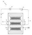
図2は、図1で説明したような燃料電池10のスタックを用いる、一般的な燃料電池パワープラント30を示す。水素(H2)などの燃料は、燃料入口32に供給され、アノードフローフィールドプレートを通って流れ、アノード触媒層に分配される。未消費の燃料は燃料出口34から流出し、リサイクルポンプ(図示せず)を通って燃料入口32に戻り、定期的に周囲環境にパージしてもよい。空気などの酸化剤は、送風機(図示せず)によって空気入口36に供給され、カソードフローフィールドプレートを通って流れ、カソード触媒層に分配される。水副生成物によって加湿された過剰なプロセス空気は、空気出口38から流出し、環境に排出される前に、ラジエータおよび/またはコンデンサ(図示せず)を通過してよい。
Figure 2 shows a typical fuel
パワープラント30は、燃料電池から熱を除去するための冷却剤ループ40をさらに含んでもよい。多くの自動車用途では、寒冷地での冷却剤の凍結を防ぐために、冷却剤は水とエチレングリコールの混合物である。ポンプ42は、冷却剤を冷却剤入口44に供給し、そこでこれは冷却プレート等(図示されていないが、通常、燃料電池10の間に配置される)を通して導かれ、該プレートの表面上に分配される。燃料電池10は、循環する冷却剤に顕熱を伝達するため、冷却剤は温かくなるが、相変化は起こらない。冷却剤出口46でスタックを離れると、冷却剤は熱交換装置48を通過し、そこで、入口44に循環して戻される前に顕熱が除かれる。一例では、熱交換装置48はラジエータである。流量制御弁またはオリフィス50を、冷却剤の流れを調整するために使用してよい。
The
図1に示すように、反応物フローフィールドプレート20はバイポーラプレートである。多くのバイポーラプレート設計は、固体材料を使用しており、ごく一部の設計では、アノード側とカソード側の両方に多孔質材料を使用している。それぞれの設計には独自の長所および短所がある。固体バイポーラプレートは、その名前が示すように、水素燃料を透過しないため、反応ガスを分離しておくのに優れている。さらに、スタックでの固体バイポーラプレートは、その不浸透性のために、密封が比較的簡単である。したがって、パワープラントスタックを加圧することができ、これによりセルの性能が向上し、セルの劣化が減少する。個体バイポーラプレートの別の利点は、不浸透性の性質により、水/エチレングリコール混合物(WEG)などの不凍液タイプの冷却剤をスタック内で使用することができることである。この不凍液タイプの冷却剤は、自動車用途などの低温環境で動作する電池に非常に有益である。しかし、WEGは膜電極を汚染するため、WEGをMEAから隔離するよう注意せねばならない。
As shown in FIG. 1, the reactant
固体バイポーラプレートは、ステンレス鋼やチタンなどの金属から製造され得る。金属プレートは、スタンピングなどの従来の大量生産方法によってフローフィールドの形状を形成できるため、大量生産が安価になる可能性がある。固体バイポーラプレートは、非多孔質カーボンから、またはポリマー(複合)材料から、製造してもよい。固体カーボンまたは複合プレートは、モールディングなどにより大量生産でき、通常、金属成形プレートよりも寸法公差を厳しく保つことができる。しかし、固体カーボンまたは複合プレートは金属プレートよりも製造コストが高くなる。 Solid bipolar plates may be manufactured from metals such as stainless steel or titanium. Metal plates can be formed to the shape of the flow field by traditional mass production methods such as stamping, making them potentially cheaper to mass produce. Solid bipolar plates may also be manufactured from non-porous carbon or from polymer (composite) materials. Solid carbon or composite plates can be mass produced by molding or the like, and typically can be held to tighter dimensional tolerances than metal molded plates. However, solid carbon or composite plates are more expensive to manufacture than metal plates.
固体バイポーラプレートは有用であり、特定の用途では有利であり得るが、欠点がある。金属プレートの欠点の1つは、非常に高い電気化学的電位で空気と水が存在するため、腐食しやすいことである。腐食層は非導電性であり、プレートの腐食が進むと燃料電池の性能が低下する。腐食を軽減するためにコーティングが開発され、プレートに適用されてきたが、この技術にも運用上の限界がある。 Although solid bipolar plates are useful and can be advantageous in certain applications, they do have drawbacks. One drawback of metal plates is that they are prone to corrosion due to the presence of air and water at very high electrochemical potentials. The corrosion layer is non-conductive, and as the plates corrode, fuel cell performance decreases. Coatings have been developed and applied to the plates to mitigate corrosion, but this technology also has operational limitations.
特に自動車産業は、燃料電池の動作寿命を5,000時間とすることを目標としている可能性がある。金属プレート上のいくつかのコーティングはこの目的を達成したと言われている。しかし、大型車両産業では30,000時間の動作寿命が必要とされ得る。現在の自動車のコーティングや構造は、その限界に近いものはない。したがって、大型車両産業では、おそらく30,000時間にも及ぶ、はるかに長い動作限界を備えた燃料電池を開発する必要がある。 The automotive industry in particular may be targeting a fuel cell operating life of 5,000 hours. Some coatings on metal plates are said to achieve this goal. However, the heavy vehicle industry may require an operating life of 30,000 hours. No current automotive coating or construction comes close to that limit. Therefore, the heavy vehicle industry needs to develop fuel cells with a much longer operating limit, perhaps even as long as 30,000 hours.
固体プレートの別の欠点は、それらが固有の水分管理能力を有さないことである。PEM燃料電池の動作においては、カソード電極で水(PEM電解質を通じたプロトン引き抜き(proton drag)から生じる水を含む)が生成される速度と、水がカソードから除去されるかまたはアノード電極に供給される速度との間で、適切な水のバランスを維持することが重要である。PEM燃料電池の場合、アノード電極に戻される水が不十分である場合、PEM電解質の隣接部分がドライアウトし、それにより、PEMを通過する水素イオンの移動速度が低下し、戻される流体のクロスオーバーが発生し、局所的な過熱が発生する。同様に、カソードからの水の除去が不十分である場合、カソード電極が浸水し、カソードへの酸化剤の供給が実質的に制限され、電流が減少する可能性がある。さらに、カソードから水が除去されすぎると、PEMがドライアウトし、水素イオンがPEMを通過する能力が制限され、電池性能が低下する可能性がある。通常、固体プレートでは、MEAのドライアウトや亀裂を防ぐために、外部加湿器などの外部水管理手段が必要である。 Another disadvantage of solid plates is that they have no inherent water management capabilities. In the operation of a PEM fuel cell, it is important to maintain a proper water balance between the rate at which water is produced at the cathode electrode (including water resulting from proton drag through the PEM electrolyte) and the rate at which water is removed from the cathode or supplied to the anode electrode. In the case of a PEM fuel cell, if insufficient water is returned to the anode electrode, the adjacent portion of the PEM electrolyte will dry out, thereby slowing the rate of hydrogen ion transport through the PEM, causing return fluid crossover, and localized overheating. Similarly, if insufficient water is removed from the cathode, the cathode electrode may become flooded, effectively limiting the supply of oxidant to the cathode and reducing the current. Furthermore, if too much water is removed from the cathode, the PEM may dry out, limiting the ability of hydrogen ions to pass through the PEM and reducing cell performance. Typically, solid plates require external water management measures, such as an external humidifier, to prevent the MEA from drying out and cracking.
多孔質バイポーラプレートは、水輸送プレートとも呼ばれ、燃料電池の電極のカソード側とアノード側の両方に使用される多孔質セパレータプレートである。多孔質バイポーラプレートは、細孔サイズを厳密に制御し、燃料電池の動作中に、液体の水のキャビティ中への該細孔を通る液体の移動を可能にするが、反応ガスの移動を妨げる、気泡バリアを作る。液体移動により膜の水和が可能となり、燃料電池内の電気化学反応から生じるカソード側の生成水の除去が可能となる。反応ガスの移動を防ぐことで、燃料と酸化剤のガスが液体の水のキャビティに漏れるのを防ぐ。 Porous bipolar plates, also called water transport plates, are porous separator plates used on both the cathode and anode sides of the electrodes in fuel cells. Porous bipolar plates have tightly controlled pore sizes to create a bubble barrier that allows liquid movement through the pores into the liquid water cavities but prevents movement of reactant gases during fuel cell operation. Liquid movement allows for hydration of the membrane and allows removal of product water on the cathode side resulting from the electrochemical reactions in the fuel cell. Preventing movement of reactant gases prevents fuel and oxidant gases from leaking into the liquid water cavities.
多孔質プレートは、フローフィールドチャネル中の過剰の水を吸い上げ、これを、蒸発により水分を失っている領域に移動させることにより、膜電極接合体の水和を保ち、優れた水分バランスを提供する。多孔質バイポーラプレートは、燃料電池の望ましい動作を維持するために、水フローフィールドにさらされる。反応ガスが低温領域から高温領域に流れるセルの局所領域では、水が該多孔質プレートから蒸発し、ガス流が水蒸気で飽和される;反応ガスが高温領域から低温領域に流れる領域では、電気化学反応で形成される生成水と冷却ガス流から凝縮される液体の水を、該多孔質プレートによって吸い上げることができる。その結果、多孔質バイポーラプレートを備える燃料電池システムの利点の1つは、これらが非常に高い耐久性を有することである。別の利点は、多孔質バイポーラプレートを備えるシステムは外部加湿器を使用する必要がないため、重量と複雑さを軽減できることである。 The porous plates keep the membrane electrode assembly hydrated by wicking up excess water in the flow field channels and transferring it to areas that are losing water through evaporation, providing an excellent moisture balance. The porous bipolar plates are exposed to a water flow field to maintain the desired operation of the fuel cell. In localized areas of the cell where reactant gases flow from low to high temperature areas, water evaporates from the porous plates and the gas stream becomes saturated with water vapor; in areas where reactant gases flow from high to low temperature areas, the porous plates can wick up product water formed in the electrochemical reactions and liquid water condensed from the cooling gas stream. As a result, one advantage of fuel cell systems with porous bipolar plates is that they are very durable. Another advantage is that systems with porous bipolar plates do not require the use of external humidifiers, reducing weight and complexity.
典型的には、ポンプ駆動の循環水ループを使用して、セルの冷却機能だけでなく、水輸送プレートの細孔を通して水を移動させ生成水を除去するための駆動力を提供することができる。 Typically, a pump-driven circulating water loop is used to provide cooling for the cells as well as the driving force to move water through the pores of the water transport plate and remove product water.
多孔質バイポーラプレートは利点を有するが、欠点もある。例えば、特定の細孔サイズを有するプレートを製造するのが難しいため、大量生産するとコストが高くなり得る。別の欠点は、多孔質プレートはシールしにくく、加圧システムの信頼性の問題につながり得ることである。別の大きな欠点は、多孔質バイポーラプレートを用いる燃料電池は、冷却剤が細孔に吸収され、MEAを汚染することを回避するため、水冷ループにWEGのような不凍液タイプの冷却剤を使用することができないことである。 Although porous bipolar plates have advantages, they also have disadvantages. For example, it can be difficult to manufacture plates with specific pore sizes, making them costly to mass produce. Another disadvantage is that porous plates are difficult to seal, which can lead to reliability issues in pressurized systems. Another major disadvantage is that fuel cells using porous bipolar plates cannot use antifreeze-type coolants, such as WEG, in the water cooling loop to avoid the coolant being absorbed into the pores and contaminating the MEA.
本開示の発明の実施形態は、燃料反応物フローフィールド、酸化剤フローフィールド、水管理フローフィールド、および、不凍液タイプの冷却剤用の専用冷却剤通路を提供する、4流体(four-fluid)プレート構造を用いることにより、バイポーラプレートに関する前述の問題の多くを解決する。実施形態は、非多孔質プレート部分と、多孔質プレート部分の両方を含み、該関連する欠点を低減または排除しながら、両方の設計の最良の側面を獲得するように思慮深く選択される。4流体バイポーラプレートは容易に製造することができ、コストを削減することができる。 The inventive embodiments of the present disclosure solve many of the aforementioned problems with bipolar plates by using a four-fluid plate structure that provides a fuel reactant flow field, an oxidant flow field, a water management flow field, and dedicated coolant passages for an antifreeze type coolant. The embodiments include both non-porous and porous plate portions, judiciously selected to capture the best aspects of both designs while reducing or eliminating the associated drawbacks. Four-fluid bipolar plates can be easily manufactured and reduce costs.
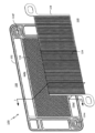
図3および図4を参照すると、燃料電池用バイポーラプレート100は、非多孔質サブプレート102および多孔質サブプレート104を含む。本発明の一実施形態において、非多孔質サブプレート102は、反応物面106(図3に示す)と、反対側の水管理面108(図4に示す)を含む。示されるように、反応物面106は、燃料フローフィールドを介して水素をMEAのアノード側へ供給する。フローフィールドの非限定的な例としては、キャビティ、多孔質基材、または、該図示される実施形態に示されるように、燃料フローフィールドチャネル110が挙げられる。非多孔質サブプレート102は、WEGなどの不凍液タイプの冷却剤を燃料電池における他のコンポーネントから分離する、内部冷却剤通路112をさらに含む(図8および11)。非多孔質サブプレート102の他の一般的な特徴には、燃料供給部114aおよび燃料戻り部114bのための、酸化剤供給部114cおよび酸化剤戻り部114dのための、水管理供給部114eおよび水管理戻り部114fのための、ならびにWEG冷却剤供給部114gおよびWEG冷却剤戻り部114hのための、内部マニホールド114が含まれ得る。シーリング手段116により、複数の燃料電池をシールし、圧力下で操作することが可能となる。
3 and 4, a
図4は、該バイポーラプレート100の反対側を示す。非多孔質サブプレート102の水管理面108は水フローフィールドを含む。該フローフィールドの非限定的な例としては、キャビティ、多孔質基材、または、該図示される実施形態に示されるように、外部循環水管理ループ150(図13)の一部分を形成し、以下に詳細に説明するように、カソードフローフィールドの適切な水管理を可能にする水チャネル118が挙げられる。水は、該水管理供給マニホールド114eを通って該プレートチャネルに入り、水管理戻りマニホールド114fを通って出る。
Figure 4 shows the opposite side of the
多孔質サブプレート104は、反応物面120と、反対側の水管理面122とを含む。反応物面120は、酸化剤フローフィールドを介してMEAのカソード側に酸化剤(例えば空気)を供給する。フローフィールドの非限定的な例としては、キャビティ、多孔質基材、または、該図示される実施形態に示されるように、この実施形態において、酸化剤フローフィールドチャネル124が挙げられる。この実施形態において、水管理面122(図3)は特徴がない(例えばフラットである)が、最適なセル性能および耐久性を維持する点で重要な役割を果たす。
The
多孔質サブプレート104は、グラファイトまたは他の炭素系材料から製造してよく、チタンまたはステンレス鋼などの金属から製造してもよい。チャネルなどの特徴は、ハイドロフォーミング、鋳造、熱成形、3Dプリンティング/付加製造、またはフライス加工/機械加工によって形成してよい。
The
前述したように、多孔質サブプレート104の細孔は、燃料電池の動作中に気泡バリアを形成するような大きさに作られている。細孔サイズは、特定の燃料電池動作条件および圧力によって決定される。グラファイトまたは他の炭素系材料について、既知の方法でプレートに細孔を形成してよい。例えば、米国特許第6,197,442号は、黒鉛粉末、強化繊維、セルロース系繊維、および熱硬化性樹脂を液体と混合してスラリーを形成し、スクリーン上にシャワーして平面シートを形成し、これを乾燥させて紙を形成する製造プロセスを詳述している。かかる紙を所望の大きさにカットしレイアップする。レイアップを、圧力と熱を加えて積層し、炭化し、黒鉛化させて、後で必要に応じて機械加工するための水輸送プレートが形成される。完成した多孔質プレートは、気泡圧力、透水性、メジアン細孔径、気孔率、面内抵抗率、および圧縮降伏強さに関して優れた物理的特性を示す。金属製の多孔質プレートの場合、細孔は、例えば、パンチプレスまたはレーザードリリングによって形成され得る。
As previously mentioned, the pores in the
図5および6は、本発明の第1実施形態による、非多孔質サブプレート102のさらなる分解図を示す。非多孔質サブプレート102は、容易に製造され互いに接合される2つのハーフプレート102Aおよび102Bから形成され得る。例えば、該ハーフプレートはステンレス鋼やチタンなどの金属から製造することができ、フローチャネルおよび他の特徴は金属スタンピングなどによって形成することができ、これら2つのハーフプレートは溶接により互いに接合させることができる。
Figures 5 and 6 show further exploded views of the
接合方法の他の非限定的な例としては、例えばレーザー溶接、ろう付け、熱可塑性接着、または接着剤が挙げられる。図示される実施形態におけるハーフプレート102Aは、反応物に面する側(図5)に、燃料フローフィールドチャネル110を含み、反対側(図6)にWEG冷却剤ハーフチャネル126Aを含む。ハーフプレート102Bは、水管理面108(図6)に水チャネル118を含み、反対側(図5)に、WEG冷却剤ハーフチャネル126Bを含む。
Other non-limiting examples of joining methods include, for example, laser welding, brazing, thermoplastic bonding, or adhesives. Half-
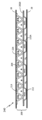
さらなる詳細は、図7および8を参照して見出すことができ、ここで、図7は、ほぼ図4に示される位置に沿ったバイポーラプレート100のカソード側の断面図を示し、図8は、図7に示されるプレートの拡大図を示す。図8を参照すると、非多孔質サブプレート102および多孔質サブプレート104がより詳細に示されている。ハーフプレート102A、102Bは、明確にするために、分離して示されている(例えば接合前)。それぞれのハーフプレートは、隆起表面128の列、および、その間に谷部130、132を含んでよく、非多孔質プレートの外表面に流体フローチャネルを画定することができる。プレートの一方の面の隆起表面128は、同じプレートの反対側に凹部134を画定する。該凹部は、2つのハーフプレート102A、102Bが共に接合される際に、内部空洞136を画定することができる。一例において、ハーフプレート102B上の谷部130は、水管理チャネル118を画定し、ハーフプレート102A上の谷部132は、燃料フローフィールドチャネル110を画定し、内部空洞136は内部不凍液冷却剤通路を画定する。
Further details can be found with reference to Figures 7 and 8, where Figure 7 shows a cross-sectional view of the cathode side of the
多孔質サブプレート104の反応物面120は、MEAに空気を供給するための酸化剤フローフィールドチャネル124を含む。一例において、チャネル124は、燃料フローフィールドチャネル110に対して横断である。多孔質サブプレート104の水管理面122は、ハーフプレート102Bのフラット隆起表面128に対して配置される。このようにして、脱塩(DI)水が、水チャネル118を通り循環されると、多孔質サブプレート104中の細孔がDI水と流体連通し、サブプレート104が液体で完全に飽和され、その状態が維持される。
The
多孔質サブプレート104における所望の多孔度は、燃料電池技術分野において知られる任意の適当な方法によって達成してよい。例えば、多孔質サブプレート104は、水輸送プレート(WTP)として組み立てられてよく、適切な粒子サイズを有するスラリーからネットシェイプ成型されてよく、または、所望の細孔サイズを達成するためにレーザー穴あけ加工されてよい。
The desired porosity in the
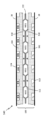
図9は、バイポーラプレート100の別の断面図を示し、該図の一部を図10に拡大して示し、1つの考えられる構造を説明する。図10を見ると、該断面図は、ハーフプレート102A、ハーフプレート102B、および多孔質サブプレート104を含む。図8と同様に、ハーフプレート102Aおよび102Bは明瞭にするために多少分離して示されている。また、WEG冷却剤ハーフチャネル126Aを形成する、ハーフプレート102Aの凹部134も示されている。
Figure 9 shows another cross-sectional view of the
多孔質サブプレート104は、ガスまたは水の漏れを防ぐために、従来の手段によって、非多孔質サブプレート102にシールされていてよい。例えば、シーリング手段116は、接着剤、入れ子(nesting)、締りばめ(interference fit)、または、成型圧縮シール、ガスケット、もしくはO-リングを受け入れるための溝を含んでいてよい。一例において、多孔質サブプレート104は、非多孔質サブプレート102の水管理面108に形成された凹部138中に入れ子状になっていてよい。凹部138は多孔質サブプレート104の平面全体に広がり、該プレートを効果的に捉え、組み立て中の適切な位置合わせを保証する。いくつかの例では、多孔質サブプレート104は他のプレートの厚さ中に実質的に埋め込まれており、全体的な厚さ寸法の増加は最小限に過ぎないため、凹部138はバイポーラプレート100の全体の厚さを減少させることができる。
The
図11は、本発明の第1実施形態のバイポーラプレート100を備えたプロトン交換膜(PEM)燃料電池140の断面図を示し、図12は、このような燃料電池のスタックを示し、図13は、開示されたバイポーラプレート100を備えた燃料電池パワープラント144の断面図を示す。図示される例において、酸化剤フローフィールドチャネル124は、燃料フローフィールドチャネル110と平行であるように示されているが、これは説明のためのものであり、これは他の実施形態についても同様である。燃料電池140は、上部および下部のユニット化電極アセンブリ28(UEA)の間に、バイポーラプレート100を含む。該バイポーラプレート100は各UEA28に接している。
11 shows a cross-sectional view of a proton exchange membrane (PEM)
動作中、水素が入口114aに導入され、非多孔質サブプレート102中の燃料フローフィールドチャネル110を通って流れることにより、UEA28のアノード側に到達する。空気は、入口114cに導入され、多孔質サブプレート104中の酸化剤フローフィールドチャネル124を通って流れることにより、UEA28のカソード側に到達する。ウォーターポンプ146は、水を、水管理ループ150中の脱塩装置148を通って循環させる。脱塩水、または脱イオン(DI)水は、水管理供給部114eを通り、非多孔質サブプレート102と多孔質サブプレート104により形成されるチャネル118を通って、スタック144に流入する。多孔質サブプレート104の細孔は水で満たされ、該サブプレートは、水を保持し、UEA28の含水を維持する、スポンジとして機能する。多孔質サブプレート104は、UEA28に該液体を直接に輸送することもできるし、あるいは、該水を蒸発させ、水蒸気を空気流を通じてUEAに移動させることもできる。多孔質サブプレート104は、カソードでの反応により形成された生成水をUEA28から除去することもできる。液体形態の生成水は、水管理ループ150における圧力を反応物の圧力よりも低く維持することにより、多孔質サブプレート104の細孔中に直接送り込むこともできる。生成水が蒸気の形態である場合、これを多孔質サブプレート上で凝縮することができ、ここで吸収され、循環水ループへと戻される。
During operation, hydrogen is introduced at
熱管理は主に、専用の隔離された冷却剤ループ152により制御される。冷却剤ポンプ154は、冷却剤を、冷却剤供給部114gを通じてスタック144に流し、冷却剤戻り部114hを通じてスタック144に流出させる。その間に、いくつかの構成では、冷却剤はセル140の表面全体に分配される。図示される実施形態において、冷却剤は、ハーフプレート102Aとハーフプレート102Bを接合することにより形成される内部通路112を通って流れる(図10)。冷却剤戻り部114hでスタックを離れると、冷却剤は熱交換装置156を通り、そこで顕熱が排出されたのち、供給部114gに循環され戻される。一例では、熱交換装置156はラジエータである。フロー制御バルブまたはオリフィス158は、冷却剤の流れを調整するために使用され得る。
Thermal management is primarily controlled by a dedicated,
非多孔質サブプレート102の不浸透性により、別個の冷却剤チューブの必要性がなくなり、冷却剤通路をサブプレート102の内部に配置することが可能となり、別個の冷却プレートを追加するいくつかの設計と比較してスペースを節約することができる。前述したように、この設計では水/エチレングリコール混合物(WEG)などの不凍液タイプの冷却剤の使用が可能であり、低温環境で動作する燃料電池にとって有益である。
The impermeability of the
図示される実施形態では、冷却剤は、ハーフプレート102Aおよび102Bを接合することによって形成された内部通路を通って流れる。しかしながら、冷却剤を分配する他の手段も本発明の範囲内で想定される。例えば、内部冷却剤通路は、冷却剤を分配する多孔質基材を含むキャビティにより定めることができる。
In the illustrated embodiment, the coolant flows through internal passages formed by joining half-
ほとんどの状況下では、開示された実施形態では外部加湿器は必要ないが、外部加湿器を追加することがシステムにとって有益であるシナリオもある。例えば、バイポーラプレート100が受動的な水管理機能のみを使用し、特に高温で乾燥した環境で運転される場合には、燃料電池が生成水を作り出すよりも早く、多孔質サブプレートから水が蒸発する可能性があった。このような環境では、本明細書の他の実施形態で詳述するような能動的冷却機能を組み込むよりも、外部加湿器159(図13)をシステムに追加することが有利である可能性がある。
While under most circumstances an external humidifier is not necessary in the disclosed embodiments, there are scenarios in which adding an external humidifier would be beneficial to the system. For example, if the
図示される実施形態では、アノードチャネル110中には多孔質媒体はない。局所的に冷たい領域が存在するなどの一部の動作条件では、アノードチャネル内で水分が凝縮し、水が蓄積し得る。アノード電極の性能低下を防止するために、水を定期的に除去する必要がある。この問題に対する従来技術の解決策には、水を吹き飛ばす試みが含まれるが、これは余分な操作手順を必要とし、寄生電力が消費される。一実施形態では、図11および図12に示されるように、1つまたは複数の小さな水抜き穴142を水素チャネルの底部から穿孔して、DI水キャビティ118と連通させることができる。水抜き穴142は、燃料チャネル110から水チャネル118に、反応ガスを逃がすことなく過剰な水を輸送するための、気泡バリアとしての大きさにすることができる。DI水ループの圧力は、アノードとカソードの圧力よりも低く維持することができる。このようにして、圧力差により水の蓄積が水抜き穴142を通ってキャビティ118内に送り込まれ、そこで水はDI水ループに戻される。
In the illustrated embodiment, there is no porous media in the
上述したように、典型的な動作条件下では、燃料電池パワープラントの熱管理は主に、不凍液冷却剤ループ152により制御され、顕熱は、冷却剤フローフィールドを通って通過する循環冷却剤に伝達される。程度は低いが、セル冷却の一部は、細孔内の生成水が蒸発する際の蒸発冷却によっても提供され得るが、蒸発冷却作用は通常、顕熱冷却剤フローシステムにおける制御パラメータとして考慮されない。
As mentioned above, under typical operating conditions, the thermal management of a fuel cell power plant is primarily controlled by the
蒸発冷却は、顕熱冷却剤フロー法と比較して、気化熱を利用して、水の体積あたりの冷却効果を最大で100対1で改善する。本開示の発明者は、特定の条件下では蒸発により冷却の強化が実現できることを確認した。したがって、本発明の一態様では、水管理ループおよび冷却剤ループの独立した操作を利用して、サーマルブーストモード、または、水回収/蓄積モードを動作させることができる。 Evaporative cooling utilizes the heat of vaporization to improve cooling effectiveness per volume of water by up to 100:1 compared to sensible coolant flow methods. The inventors of the present disclosure have determined that under certain conditions enhanced cooling can be achieved through evaporation. Thus, in one aspect of the present invention, independent operation of the water management loop and the coolant loop can be utilized to operate in a thermal boost mode or a water recovery/accumulation mode.
サーマルブーストモードでは、スタックが多量の電力を要求している場合など、有限の継続時間にわたって追加の冷却が必要である。燃料電池車両(特にトラック)では、サーマルブーストモードは、急な坂道や長い車道を登るとき、暑い日に高出力で動作するとき、または、ラジエータが冷却要求を十分に処理できるほど大きくないあらゆる他のシナリオにおいて、役立ち得る。サーマルブーストモードでは、熱管理方法が顕熱冷却から蒸発冷却に移行し、より大きい冷却能力が与えられる。蒸発冷却は、サーマルブーストモードの全冷却機能の大部分を占めることができ、一部の設計シナリオでは90%以上を占める場合がある。 In thermal boost mode, additional cooling is needed for a finite duration, such as when the stack is demanding a lot of power. In fuel cell vehicles (especially trucks), thermal boost mode can be useful when climbing steep hills or long roads, when operating at high power on hot days, or in any other scenario where the radiator is not large enough to adequately handle the cooling demands. In thermal boost mode, the thermal management method shifts from sensible cooling to evaporative cooling, providing more cooling capacity. Evaporative cooling can account for a large portion of the total cooling function in thermal boost mode, and in some design scenarios can account for more than 90%.
動作中、追加の冷却が必要な場合、または必要であると計算される場合、第1ステップで、冷却剤流量(すなわち、WEG)が減少し、これにより顕熱冷却能力が低下する。その結果、スタックの温度が上昇し始め、細孔からの水の蒸発速度が増加し、大幅な蒸発冷却が実現される。次に、第2のステップでは、蒸発冷却の度合いを高めるために、燃料電池の温度を上昇させるか、または温度を維持する。水の蒸発の増加を補い、細孔が乾燥して気泡バリアが失われるのを防ぐために、第3のステップで、水管理フローフィールドを通る水の流量を増加させることができる。一例では、水の流量の増加は、水管理フローフィールドと流体連通するポンプ駆動の循環水管理ループを提供し、ポンプによる水の流量を増加させることによって実現される。 During operation, if additional cooling is needed or calculated to be needed, in a first step, the coolant flow rate (i.e., WEG) is reduced, which reduces the sensible cooling capacity. As a result, the temperature of the stack begins to increase, which increases the rate of water evaporation from the pores and achieves significant evaporative cooling. Then, in a second step, the temperature of the fuel cell is increased or maintained to increase the degree of evaporative cooling. To compensate for the increased water evaporation and prevent the pores from drying out and losing the bubble barrier, in a third step, the water flow rate through the water management flow field can be increased. In one example, the increased water flow rate is achieved by providing a pump-driven circulating water management loop in fluid communication with the water management flow field and increasing the water flow rate through the pump.
開示された蒸発冷却方式は、大きな短時間の熱要求を処理する能力がより大きいため、より優れた短期の熱管理制御戦略を提供する。冷却剤の流量を低い値に調整し、適当なレベルの蒸発冷却と所望のスタック温度を達成することができる。 The disclosed evaporative cooling scheme provides a better short-term thermal management control strategy due to its greater ability to handle large short-term heat demands. The coolant flow rate can be adjusted to a lower value to achieve the appropriate level of evaporative cooling and desired stack temperature.
開示されたサーマルブーストモードは、水管理ループ内の水量を、生成水の形成によって同時に補充できる量以上に、枯渇させる。したがって、サーマルブーストモードは比較的短期間が意図される。しかしながら、本発明の別の態様では、水管理ループと冷却剤ループの独立した動作を、水回収/蓄積モードを操作するために利用してもよい。水回収/蓄積モードでは、冷却剤流量(すなわちWEG)を通常の速度よりも増加させ、蒸発冷却が減少し、凝縮によってセル内に過剰の水が生成される。過剰な生成水を収集し、将来のサーマルブーストモードで使用するために保持することができる。 The disclosed thermal boost mode depletes the amount of water in the water management loop beyond what can be simultaneously replenished by the formation of product water. Thus, the thermal boost mode is intended to be relatively short term. However, in another aspect of the invention, the independent operation of the water management loop and the coolant loop may be utilized to operate a water recovery/accumulation mode. In the water recovery/accumulation mode, the coolant flow rate (i.e., WEG) is increased above normal rates, evaporative cooling is reduced, and excess water is generated in the cell by condensation. The excess product water can be collected and held for use in a future thermal boost mode.
一実施形態において、水回収/蓄積モードを、車両が平地を走行しているときなどの、スタックを必要とせず、ラジエータを通る空気流が十分な冷却をもたらす、サイクルの一部分中に動作させることもできる。第1のステップで、追加の生成水が必要とされるか、必要と計算される際、冷却剤ループ内の冷却剤流量(すなわちWEG)を増加させ、顕熱冷却を増加させる。その結果、スタック温度が低下し、細孔から蒸発する生成水の量が減少し、代わりに凝集水が形成される。第2のステップで、余剰の生成水を凝縮させるために、燃料電池の温度を下げるが、温度を維持する。水蒸発の減少を補填し、セルフラッディングを防止するために、第3のステップで、水管理フローフィールドを通る水の流量を減少させてよい。一例では、水の流量の減少を、水管理フローフィールドと流体連通するポンプ駆動の循環水管理ループを提供し、該ポンプを用いて水の流量を減少させることにより実現してもよい。 In one embodiment, the water recovery/accumulation mode may also be operated during portions of the cycle where the stack is not required and the airflow through the radiator provides sufficient cooling, such as when the vehicle is traveling on level ground. In a first step, when additional product water is required or calculated to be required, the coolant flow rate (i.e., WEG) in the coolant loop is increased to increase sensible cooling. As a result, the stack temperature is reduced and the amount of product water that evaporates from the pores is reduced, forming condensed water instead. In a second step, the temperature of the fuel cell is reduced, but maintained, to condense the excess product water. To compensate for the reduced water evaporation and prevent self-cladding, in a third step, the water flow rate through the water management flow field may be reduced. In one example, the reduction in water flow rate may be achieved by providing a pump-driven circulating water management loop in fluid communication with the water management flow field and using the pump to reduce the water flow rate.
別の実施形態では、燃料電池コントローラは、サーマルブーストモード、または、水回収/蓄積モードが保証されるかどうか、また保証される場合にどの程度まで保証されるかを決定するために、センサ入力または環境入力を受信してもよい。センサ入力の非限定的な例としては、空気流量、カソード排気温度、カソード排気圧力、総貯水容量、水在庫、水温度、周囲温度、冷却剤戻り温度、および水ループ出口圧力などが挙げられ得る。コントローラは、センサ入力値に応じて、冷却剤ポンプおよび/またはウォーターポンプの流量設定を命令することができる。 In another embodiment, the fuel cell controller may receive sensor or environmental inputs to determine whether and to what extent a thermal boost mode or a water recovery/accumulation mode is warranted. Non-limiting examples of sensor inputs may include air flow rate, cathode exhaust temperature, cathode exhaust pressure, total water storage capacity, water inventory, water temperature, ambient temperature, coolant return temperature, and water loop outlet pressure. The controller may command coolant pump and/or water pump flow rate settings depending on the sensor input values.
燃料電池コントローラは、外部環境要因からの入力も受信し得る。非限定的な例としては、ペイロードタイミング、車両ルート、GPS座標、道路勾配、天気予報、時刻、およびドライバーの行動が挙げられる。一例では、コントローラは、急勾配または延長された車道勾配が近づいていることを示すGPSルートデータを受信し得る。コントローラは、水回収/蓄積モードを動作させるように十分に前もってスタックに命令することができ、生成水を収集し、それを貯水槽に保持することができる。次いで、車両が勾配に遭遇する際、コントローラはサーマルブーストモードを動作するようスタックに命令することができる。 The fuel cell controller may also receive inputs from external environmental factors. Non-limiting examples include payload timing, vehicle route, GPS coordinates, road grade, weather forecast, time of day, and driver actions. In one example, the controller may receive GPS route data indicating a steep or extended roadway grade is approaching. The controller may command the stack well in advance to operate a water recovery/accumulation mode, which can collect product water and hold it in a water reservoir. Then, when the vehicle encounters a grade, the controller may command the stack to operate a thermal boost mode.
サーマルブーストモード、および、水回収/蓄積モードの動作は、開示されたハイブリッドバイポーラプレートに限定されない。本発明者らは、本開示された動作方法は、米国特許第7,135,247号に開示されるような、不凍液タイプの冷却剤ループが水管理ループとは独立して動作される任意の4流体燃料電池パワープラントにおいて可能であり有益であり得ると想定する。該‘247特許は、全ての他の燃料電池間に並べられた別個の個々の冷却プレートを開示している。 The thermal boost and water recovery/storage modes of operation are not limited to the disclosed hybrid bipolar plates. The inventors envision that the disclosed method of operation may be possible and beneficial in any four-fluid fuel cell power plant where an antifreeze type coolant loop is operated independently of the water management loop, such as that disclosed in U.S. Pat. No. 7,135,247, which discloses separate individual cooling plates aligned between every other fuel cell.
開示されたサーマルブーストモードおよび水回収/蓄積モードは、従来技術の3流体スタックに勝るいくつかの利点とアドバンテージを提供する。利点の1つは、サーマルブーストモードは、高出力の際に、ラジエータおよびファンを増やす代わりに実際にチューニングダウンするため、寄生電力を低減することである。従来技術のスタックでは、ラジエータおよびファンを激しく稼働させると効率が低下する。反対に、ラジエータのチューニングダウンは効率を高める。 The disclosed thermal boost and water recovery/storage modes offer several benefits and advantages over prior art three-fluid stacks. One benefit is that the thermal boost mode reduces parasitic power because at high power output the radiator and fan are actually tuned down instead of increased. In prior art stacks, running the radiator and fan harder reduces efficiency. Conversely, tuning down the radiator increases efficiency.
開示されたサーマルブーストモードの別の利点は、燃料電池内で達成できる代替の冷却手段があるため、ラジエータのサイズを小さくでき得ることである。従来技術の3流体設計では、はるかに大型のラジエータが使用されているが、これはより高価であり、車両の重量が増加するため、性能が低下する。これは特に燃料電池トラックに当てはまる。 Another advantage of the disclosed thermal boost mode is that the size of the radiator may be reduced due to alternative cooling means that can be achieved within the fuel cell. Prior art three-fluid designs use much larger radiators that are more expensive and add weight to the vehicle, reducing performance. This is especially true for fuel cell trucks.
図14は、本発明の第2の実施形態による4流体バイポーラプレート200を有する燃料電池240の断面図を示す。ハーフプレート102Aは、図11に示したものと同じ構造であってもよいが、ハーフプレート102Bは単純なフラットプレート202Bに置き換えられる。フラットプレートは、ハーフプレート102Aと同じ材料から形成され得る。この実施形態における多孔質サブプレート204は、該プレートの第1の面に酸化剤フローフィールドチャネル224を含み、反対側の第2の面にDI水チャネル218を含む。この構造では、非多孔質サブプレート102は水チャネルを有さない。この実施形態の1つの利点は、薄型であり、スタックの高さと重量が低減されることである。WEG冷却剤通路212のサイズも半分に低減されるが、これは冷却剤流量を増加させることによって補償することができる。
Figure 14 shows a cross-sectional view of a
図15は、本発明の第3の実施形態による4流体バイポーラプレート300を有する燃料電池340の断面図を示す。この実施形態では、DI水はスタック全体を循環せず、該水はセル340内のみを循環する。ハーフプレート102Aは、図11に示したものと同じ構造であってよいが、ハーフプレート102Bは単純なフラットプレート302Bに置き換えられている。該フラットプレートは、ハーフプレート102Aと同じ材料から形成され得る。水輸送プレートとして構築され得るサブプレート304は、DI水のための多孔質基材として機能し、事実上はDI水「スポンジ」である:空気から生成水と加湿水を収集し、それを循環させてセル反応物チャネル324の入口に戻し、UEA28を潤す。セル内循環は、細孔内の水が反応物チャネルの入口で蒸発すると、新しい水が、細孔がまだ飽和しているチャネル324のさらに下流から吸い上げられるような、細孔ウィッキングによって起こる。このサイクルは受動的に継続し、チャネルの入口で蒸発が起こり、チャネルの出口で凝縮が起こる。この実施形態は、それほど複雑ではなく、外部ポンプおよび配管の費用を節約し、寄生電力を消費しない、受動的な水管理の利点を提供する。
15 shows a cross-sectional view of a
図16は、本発明の第4の実施形態による4流体バイポーラプレート400を有する燃料電池440の断面図を示す。この実施形態において、構成は、追加のセパレータプレート460が内部WEG冷却剤通路を2つの別個のチャネル(WEG1、WEG2として示す)に分割すること以外、図11に示したものと本質的に同じである。個別のチャネルは、セル全体の熱分布を均一にするために使用され得り、すなわち、必要な箇所により高い冷却能力を追加することができる。一例では、2つの別個のチャネルは、異なる組成の冷却剤または完全に異なる流体を運ぶことができる。
Figure 16 shows a cross-sectional view of a
図17は、本発明の第5の実施形態による4流体バイポーラプレート500を有する燃料電池540の断面図を示す。この実施形態では、カソード側構造およびWEG内部冷却剤通路は、図9に示したものと本質的に同じであるが、アノード側は、水素をUEA28に供給するために多孔質サブプレート562を使用する。非多孔質サブプレート102は変更されていないが、燃料反応物チャネル(図8)を画定するサブプレート102Aの谷部132の代わりに、この実施形態では、これらが、多孔質アノードサブプレート562の水和を維持するために、水チャネル518を画定する。カソード側と同様に、多孔質アノードサブプレート562は、UEA28に隣接する燃料フローフィールドチャネル510を含む。
17 shows a cross-sectional view of a
図18は、本発明の第6の実施形態によるバイポーラプレート600を有する燃料電池 640の断面図を示す。この実施形態は、WEG冷却剤用の内部冷却剤通路を含まないため、3流体系である。該バイポーラプレートは、非多孔質サブプレート602および多孔質サブプレート104を含む。該多孔質サブプレートは図11に示したものと本質的に同じである。該非多孔質サブプレート602は、単一のプレートを含み、それに溶接または別の方法で接合されたフラットプレートがない点において、前の実施形態とは異なる。したがって、サブプレート602は、水チャネル618を画定する水管理面と、反対側の、燃料フローフィールドチャネル610を画定する反応物面を含む。
18 shows a cross-sectional view of a
図19は、本発明の第7の実施形態による4流体バイポーラプレート700を有する燃料電池740の断面図を示す。この実施形態では、バイポーラプレート700は、カソード側に多孔質サブプレート704を含み、アノード側にハイブリッドサブプレート766を含む。サブプレート704は、サブプレート204(図14)と本質的に同じであり、一方の側に酸化剤フローフィールド724を有し、反対側に水フローフィールド718を有する。ハイブリッドサブプレート766は、多孔質部分と非多孔質部分とを含む。非多孔質部分は、冷却剤が他のセル構成要素にさらされるのを隔離する内部冷却剤通路712を画定する。冷却剤は、WEGなどの不凍液タイプの冷却剤であってよい。多孔質部分は、燃料反応物フローフィールド710を水フローフィールド718に流体接続する複数の細孔768を画定する。細孔768は、水素ガスを水の空洞に逃がすことなく、過剰な水を燃料フローフィールド710から水フローフィールド718に輸送するための、気泡バリアとして寸法設定されている。
19 shows a cross-sectional view of a
一例では、サブプレート766は、内部冷却剤通路712を形成するための、ハーフプレート766B(図14の202Bに類似)に接合されたハーフプレート766A(図8の102Aに類似)を含んでよい。フラットプレート766Bは、ハーフプレート766Aと同じ材料から形成され得る。ハーフプレート766A、766Bは、例えば溶接、レーザー溶接、ろう付け、熱可塑性接着、または接着剤などの前述の技術のいずれかにより接合されていてよい。接合後、細孔768を、レーザードリリングなどの任意の適当な技術によって形成してよい。
In one example, the sub-plate 766 may include a half-
さらなる実施形態は、燃料と酸化剤反応物を交換することによって実現され得る。例えば、前の実施形態では、空気が多孔質サブプレート104のチャネルを通って流れ、水素が非多孔質サブプレート102のチャネルを通って流れると説明した。位置を交換すること、つまり水素が多孔質サブプレート104のチャネルを通って流れ、空気が非多孔質サブプレート102のチャネルを通って流れることも、本発明の範囲内であると考えられる。
Further embodiments may be realized by swapping the fuel and oxidant reactants. For example, the previous embodiment described air flowing through the channels of the
開示された燃料電池システムの改良点の1つは、非多孔質金属サブプレート上の電解腐食の防止である。電解腐食は、多孔質カーボンサブプレートと金属サブプレートとの間の界面164(図11および13)で、それらの電位差のために、発生する可能性がある。金属が酸化し始めると、酸化物層が非導電性になるために、セルは性能低下し始める。この問題に対する従来技術の解決策としては(システムに非多孔質カーボンが含まれている場合)、腐食を防ぐために金属プレートにコーティングを塗布することが挙げられる。開示された燃料電池システムは、コーティングの恩恵をなお受け得るが、該システムは、脱塩/脱イオン水ループが、金属と炭素との間の界面164を一掃し、通常蓄積して界面を非導電性にする可能性のある、あらゆる腐食生成物を除去するため、コーティングを利用する必要がなくあり得る。実際、該界面を循環する水は酸化物の蓄積を防止する。
One of the improvements of the disclosed fuel cell system is the prevention of galvanic corrosion on the non-porous metal subplate. Galvanic corrosion can occur at the interface 164 (FIGS. 11 and 13) between the porous carbon subplate and the metal subplate due to their potential difference. When the metal begins to oxidize, the cell begins to degrade because the oxide layer becomes non-conductive. Prior art solutions to this problem (when the system includes non-porous carbon) include applying a coating to the metal plate to prevent corrosion. While the disclosed fuel cell system can still benefit from a coating, the system may not need to utilize a coating because the demineralized/deionized water loop sweeps the
本明細書に記載される方法のサンプルは、以下のとおりである: A sample of the method described herein is as follows:
(1)燃料電池における炭素/金属界面の腐食を防止する方法であって、該方法は以下のステップを含む、方法: (1) A method for preventing corrosion of a carbon/metal interface in a fuel cell, the method comprising the steps of:
金属サブプレートと多孔質サブプレートとを含むバイポーラプレートを提供するステップであって、該金属サブプレートは少なくとも1つの水管理面を有し、該多孔質サブプレートは反応物面と反対側の水管理面を有し、該多孔質サブプレートの水管理面は、界面を形成するように、該金属サブプレートの水管理面と隣接する、ステップ; Providing a bipolar plate including a metal subplate and a porous subplate, the metal subplate having at least one water management surface, the porous subplate having a water management surface opposite a reactant surface, the water management surface of the porous subplate being adjacent to the water management surface of the metal subplate to form an interface;
該バイポーラプレートに隣接する、ユニット化された電極アセンブリを提供するステップ; Providing a unitized electrode assembly adjacent to the bipolar plate;
燃料および酸化剤反応物を、該バイポーラプレート上の反応物フローフィールドから、該ユニット化された電極アセンブリへと流し、電気化学反応を開始するステップ; Flowing fuel and oxidant reactants from the reactant flow fields on the bipolar plates to the unitized electrode assembly to initiate an electrochemical reaction;
界面で形成された腐食生成物を一掃するために、水管理ループを通り、金属サブプレートおよび多孔質サブプレートの水管理面へと、水を流すステップ;および、 Flowing water through the water management loop and onto the water management surfaces of the metal subplate and the porous subplate to sweep away corrosion products formed at the interfaces; and
水管理ループ内を流れる水を脱イオン化および脱塩化するステップ。 A step of deionizing and desalting the water flowing through the water management loop.
(2)上記(1)に記載の燃料電池における炭素/金属界面での腐食を防止する方法であって、バイポーラプレート内に内部冷却剤通路を形成し、該内部冷却剤通路に不凍液タイプの冷却剤を流すステップをさらに含む、方法。 (2) A method for preventing corrosion at the carbon/metal interface in the fuel cell described in (1) above, further comprising the steps of forming internal coolant passages in the bipolar plate and flowing an antifreeze-type coolant through the internal coolant passages.
(10)以下のステップを含む、4流体燃料電池をサーマルブーストモードで動作させる方法: (10) A method for operating a four-fluid fuel cell in thermal boost mode, comprising the steps of:
酸化剤フローフィールド、燃料反応物フローフィールド、水管理フローフィールド、および、顕熱を除去するように動作可能な独立した循環冷却剤ループを含む、4流体燃料電池を提供するステップであって、該冷却剤ループは冷却剤フローフィールドと流体連通する、ステップ; Providing a four-fluid fuel cell including an oxidant flow field, a fuel reactant flow field, a water management flow field, and an independent circulating coolant loop operable to remove sensible heat, the coolant loop being in fluid communication with the coolant flow field;
冷却剤ループにおける冷却剤の流量を低下させ、顕熱冷却能を低下させるステップ;および Reducing the flow rate of the coolant in the coolant loop to reduce the sensible cooling capacity; and
蒸発冷却を増加させるために、燃料電池の温度を維持または上昇させるステップ。 Maintaining or increasing the temperature of the fuel cell to increase evaporative cooling.
(11)上記(10)に記載の4流体燃料電池を動作させる方法であって、ここで、該冷却剤は不凍液タイプの冷却剤である、方法。 (11) A method of operating a four-fluid fuel cell as described in (10) above, wherein the coolant is an antifreeze type coolant.
(12)上記(10)に記載の4流体燃料電池を動作させる方法であって、ここで、該酸化剤フローフィールドおよび該燃料反応物フローフィールドの少なくとも1つは、水管理フローフィールドと流体接続された複数の細孔を含み、該細孔は気泡バリアとして構成される、方法。 (12) A method of operating a four-fluid fuel cell as described in (10) above, wherein at least one of the oxidant flow field and the fuel reactant flow field includes a plurality of pores fluidly connected to a water management flow field, the pores being configured as bubble barriers.
(13)上記(10)に記載の4流体燃料電池を動作させる方法であって、ここで、該4流体燃料電池を提供するステップは、酸化剤フローフィールド、燃料反応物フローフィールド、内部冷却剤通路、および水管理フローフィールドを含むハイブリッドバイポーラプレートを提供することを含む、方法。 (13) A method of operating a four-fluid fuel cell as described in (10) above, wherein the step of providing the four-fluid fuel cell includes providing a hybrid bipolar plate including an oxidant flow field, a fuel reactant flow field, internal coolant passages, and a water management flow field.
(14)上記(10)に記載の4流体燃料電池を動作させる方法であって、蒸発の増加を補償するために、水管理フローフィールドを通る水の流量を増加させるステップをさらに含む、方法。 (14) A method of operating a four-fluid fuel cell as described in (10) above, further comprising the step of increasing the flow rate of water through the water management flow field to compensate for increased evaporation.
(15)上記(14)に記載の4流体燃料電池を動作させる方法であって、ここで、該4流体燃料電池を提供するステップは、水管理フローフィールドと流体連通する循環水管理ループを提供することをさらに含む、方法。 (15) A method of operating a four-fluid fuel cell as described in (14) above, wherein the step of providing the four-fluid fuel cell further includes providing a circulating water management loop in fluid communication with the water management flow field.
(20)以下のステップを含む、4流体燃料電池内に生成水を蓄積し保持する方法: (20) A method for storing and retaining product water in a four-fluid fuel cell, comprising the steps of:
酸化剤フローフィールド、燃料反応物フローフィールド、水管理フローフィールド、および、顕熱を除去するように動作可能な独立した循環冷却剤ループを含む、4流体燃料電池を提供するステップであって、該冷却剤ループは冷却剤フローフィールドと流体連通する、ステップ; Providing a four-fluid fuel cell including an oxidant flow field, a fuel reactant flow field, a water management flow field, and an independent circulating coolant loop operable to remove sensible heat, the coolant loop being in fluid communication with the coolant flow field;
冷却剤ループにおける冷却剤の流量を増加させ、顕熱冷却能を増加させるステップ;および Increasing the flow rate of coolant in the coolant loop to increase sensible cooling capacity; and
余剰の生成水を凝縮させるために、温度を維持または低下させるステップ。 Maintaining or reducing the temperature to condense excess product water.
(21)上記(20)に記載の、4流体燃料電池内に生成水を蓄積し保持する方法であって、余剰の生成水を貯水する貯水槽を提供するステップをさらに含み、該貯水槽は水管理ループと流体連通する、方法。 (21) The method for accumulating and retaining product water in a four-fluid fuel cell according to (20) above, further comprising the step of providing a water tank for storing excess product water, the water tank being in fluid communication with the water management loop.
(22)上記(20)に記載の、4流体燃料電池内に生成水を蓄積し保持する方法であって、水管理フローフィールドを通る水の流量を低下させ、余剰の生成水を蓄積し、減少した蒸発を補償するステップをさらに含む、方法。 (22) A method for storing and retaining product water in a four-fluid fuel cell as described in (20) above, further comprising the step of reducing the flow rate of water through the water management flow field to store excess product water and compensate for reduced evaporation.
(23)上記(22)に記載の、4流体燃料電池内に生成水を蓄積し保持する方法であって、4流体燃料電池を提供するステップは、水管理フローフィールドと流体連通する循環水管理ループを提供することをさらに含む、方法。 (23) A method for storing and retaining product water in a four-fluid fuel cell as described in (22) above, wherein the step of providing a four-fluid fuel cell further includes providing a circulating water management loop in fluid communication with the water management flow field.
(24)上記(10)または(20)のいずれかに記載の方法であって、コントローラが、センサデータに応じて、冷却剤ポンプおよびウォーターポンプの流量設定を命令し、該センサデータは、空気流量、カソード排気温度、カソード排気圧力、総貯水容量、水在庫、水温度、周囲温度、冷却剤戻り温度、および水ループ出口圧力の少なくとも1つを含む、方法。 (24) A method according to any of (10) or (20) above, wherein the controller commands flow settings of the coolant pump and the water pump in response to sensor data, the sensor data including at least one of air flow, cathode exhaust temperature, cathode exhaust pressure, total water capacity, water inventory, water temperature, ambient temperature, coolant return temperature, and water loop outlet pressure.
(25)上記(10)または(20)のいずれかに記載の方法であって、コントローラが、環境要因に応じて、冷却剤ポンプおよびウォーターポンプの流量設定を命令し、該環境要因は、ペイロードタイミング、車両ルート、GPS座標、道路勾配、天気予報、時刻、およびドライバーの行動の少なくとも1つを含む、方法。
〔1〕以下:
非多孔質サブプレートであって、該非多孔質サブプレートは、第1水管理面と、該第1水管理面と反対側の第2水管理面とを含み、以下:
燃料供給内部マニホールド貫通路および燃料戻り内部マニホールド貫通路;
酸化剤供給内部マニホールド貫通路および酸化剤戻り内部マニホールド貫通路;
水管理供給内部マニホールド貫通路および水管理戻り内部マニホールド貫通路;
冷却剤供給内部マニホールド貫通路および冷却剤戻り内部マニホールド貫通路;および
一方の端で前記冷却剤供給内部マニホールド貫通路と流体連通し、他方の端で前記冷却剤戻り内部マニホールド貫通路と流体連通する、内部冷却剤通路であって、該内部冷却剤通路は、燃料供給内部マニホールド貫通路および燃料戻り内部マニホールド貫通路と、酸化剤供給内部マニホールド貫通路および酸化剤戻り内部マニホールド貫通路との間の領域にわたって延びる、内部冷却剤通路
を画定する、非多孔質サブプレート;
反応物面と、反対側の水管理面とを含む、第1多孔質サブプレートであって、該反応物面は、前記燃料供給内部マニホールド貫通路および前記酸化剤供給内部マニホールド貫通路のうちの1方と流体連通する第1反応物フローフィールドを含み、該水管理面は、前記非多孔質サブプレートの前記第1水管理面と流体連通する、第1多孔質サブプレート;および
反応物面と、反対側の水管理面とを含む、第2多孔質サブプレートであって、該反応物面は、前記燃料供給内部マニホールド貫通路および前記酸化剤供給内部マニホールド貫通路のうちの他方と流体連通する第2反応物フローフィールドを含み、該水管理面は、前記非多孔質サブプレートの前記第2水管理面と流体連通する、第2多孔質サブプレート
を含む、燃料電池用バイポーラプレート。
〔2〕前記第1多孔質サブプレートおよび前記第2多孔質サブプレートの少なくとも1つは、前記非多孔質サブプレートの凹んだ周囲部(recessed perimeter)内で入れ子状シールを形成する、〔1〕に記載のバイポーラプレート。
〔3〕前記非多孔質サブプレートの少なくとも1つの面は、水管理フローフィールドを画定する、〔1〕に記載のバイポーラプレート。
〔4〕前記水管理フローフィールドは水フローフィールドチャネルを含む、〔3〕に記載のバイポーラプレート。
〔5〕前記非多孔質サブプレートは、第2ハーフプレートに接合された第1ハーフプレートを含む、〔1〕に記載のバイポーラプレート。
〔6〕前記内部冷却剤通路は、接合された前記第1ハーフプレートおよび第2ハーフプレートにより画定される、〔5〕に記載のバイポーラプレート。
〔7〕前記内部冷却剤通路は不凍液タイプの冷却剤に適合性である、〔1〕に記載のバイポーラプレート。
〔8〕前記第1多孔質サブプレートおよび前記第2多孔質サブプレートの少なくとも1つは、気泡バリア細孔構造であって、前記細孔構造を通る液体の移送を可能にし、前記細孔構造を通る反応ガスの移送を防止するのに適した、気泡バリア細孔構造を含む、〔1〕に記載のバイポーラプレート。
〔9〕前記第1多孔質サブプレートおよび前記第2多孔質サブプレートのいずれもが、気泡バリア細孔構造であって、前記細孔構造を通る液体の移送を可能にし、前記細孔構造を通る反応ガスの移送を防止する、気泡バリア細孔構造を含む、〔8〕に記載のバイポーラプレート。
〔10〕燃料電池バイポーラプレートアセンブリ用の非多孔質サブプレートであって、
第1水管理面と、該第1水管理面の反対側の第2水管理面とを含み、
前記非多孔質サブプレートは、以下:
燃料供給内部マニホールド貫通路および燃料戻り内部マニホールド貫通路;
酸化剤供給内部マニホールド貫通路および酸化剤戻り内部マニホールド貫通路;
水管理供給内部マニホールド貫通路および水管理戻り内部マニホールド貫通路;
冷却剤供給内部マニホールド貫通路および冷却剤戻り内部マニホールド貫通路;および
一方の端で前記冷却剤供給内部マニホールド貫通路と流体連通し、他方の端で前記冷却剤戻り内部マニホールド貫通路と流体連通する、内部冷却剤通路であって、該内部冷却剤通路は、燃料供給内部マニホールド貫通路および燃料戻り内部マニホールド貫通路と、酸化剤供給内部マニホールド貫通路および酸化剤戻り内部マニホールド貫通路との間の領域にわたって延びる、内部冷却剤通路
を画定する、非多孔質サブプレート。
〔11〕前記第1水管理面は、第1多孔質サブプレートを受け入れるのに適した第1の凹んだ周囲部を含む、〔10〕に記載の非多孔質サブプレート。
〔12〕前記第1の凹んだ周囲部はさらに、前記第1多孔質サブプレートと共に入れ子状シールを与えるのに適している、〔11〕に記載の非多孔質サブプレート。
〔13〕前記第2水管理面は、第2多孔質サブプレートを受け入れるのに適した第2の凹んだ周囲部を含む、〔11〕に記載の非多孔質サブプレート。
〔14〕前記第2の凹んだ周囲部はさらに、前記第2多孔質サブプレートと共に入れ子状シールを与えるのに適している、〔13〕に記載の非多孔質サブプレート。
〔15〕第2ハーフプレートに接合された第1ハーフプレートをさらに含み、それにより内部冷却剤通路を画定する、〔10〕に記載の非多孔質サブプレート。
(25) A method according to any of (10) or (20) above, wherein the controller commands flow settings of the coolant pump and the water pump in response to environmental factors, the environmental factors including at least one of payload timing, vehicle route, GPS coordinates, road gradient, weather forecast, time of day, and driver behavior.
[1] The following:
1. A non-porous subplate, the non-porous subplate including a first water management surface and a second water management surface opposite the first water management surface, the non-porous subplate having:
a fuel supply internal manifold through-passage and a fuel return internal manifold through-passage;
oxidant supply and return internal manifold passages;
Water management supply internal manifold penetrations and water management return internal manifold penetrations;
coolant supply and return internal manifold through-passages; and
an internal coolant passage in fluid communication with the coolant supply internal manifold throughpassage at one end and in fluid communication with the coolant return internal manifold throughpassage at the other end, the internal coolant passage extending across an area between the fuel supply and fuel return internal manifold throughpassages and the oxidant supply and oxidant return internal manifold throughpassages;
a non-porous subplate defining
a first porous subplate including a reactant side and an opposing water management side, the reactant side including a first reactant flow field in fluid communication with one of the fuel supply internal manifold throughways and the oxidant supply internal manifold throughways, the water management side in fluid communication with the first water management side of the non-porous subplate; and
a second porous subplate including a reactant face and an opposing water management face, the reactant face including a second reactant flow field in fluid communication with the other of the fuel supply internal manifold throughways and the oxidant supply internal manifold throughways, the water management face in fluid communication with the second water management face of the non-porous subplate;
13. A bipolar plate for a fuel cell comprising:
2. The bipolar plate of claim 1, wherein at least one of the first and second porous subplates forms a nested seal within a recessed perimeter of the non-porous subplate.
[3] The bipolar plate of [1], wherein at least one surface of the non-porous subplate defines a water management flow field.
[4] The bipolar plate of [3], wherein the water management flow field includes a water flow field channel.
5. The bipolar plate of claim 1, wherein the non-porous sub-plate comprises a first half-plate joined to a second half-plate.
[6] The bipolar plate according to [5], wherein the internal coolant passages are defined by the first and second half plates joined together.
7. The bipolar plate of claim 1, wherein the interior coolant passages are compatible with antifreeze type coolants.
[8] The bipolar plate of [1], wherein at least one of the first porous subplate and the second porous subplate comprises a bubble barrier pore structure suitable for allowing transport of a liquid through the pore structure and preventing transport of a reactant gas through the pore structure.
[9] The bipolar plate of [8], wherein both the first porous subplate and the second porous subplate include a bubble barrier pore structure that allows transport of liquid through the pore structure and prevents transport of reactant gas through the pore structure.
[10] A non-porous subplate for a fuel cell bipolar plate assembly, comprising:
a first water management surface and a second water management surface opposite the first water management surface;
The non-porous subplate comprises:
a fuel supply internal manifold through-passage and a fuel return internal manifold through-passage;
oxidant supply and return internal manifold passages;
Water management supply internal manifold penetrations and water management return internal manifold penetrations;
coolant supply and return internal manifold through-passages; and
an internal coolant passage in fluid communication with the coolant supply internal manifold throughpassage at one end and in fluid communication with the coolant return internal manifold throughpassage at the other end, the internal coolant passage extending across an area between the fuel supply and fuel return internal manifold throughpassages and the oxidant supply and oxidant return internal manifold throughpassages;
A non-porous subplate defining a
11. The non-porous subplate of
[12] The non-porous subplate of [11], wherein the first recessed peripheral portion is further adapted to provide a nested seal with the first porous subplate.
13. The non-porous subplate of claim 11, wherein the second water management surface includes a second recessed peripheral portion adapted to receive a second porous subplate.
[14] The non-porous subplate of [13], wherein the second recessed peripheral portion is further adapted to provide a nested seal with the second porous subplate.
[15] The non-porous subplate of [10], further comprising a first half-plate joined to a second half-plate, thereby defining an internal coolant passage.
Claims (15)
反応物面と、反対側の水管理面とを含む、多孔質サブプレートであって、該反応物面は第1反応物フローフィールドを含み、該水管理面は、前記非多孔質サブプレートの前記水管理面と流体連通する、多孔質サブプレート
を含む、燃料電池用バイポーラプレート。 1. A bipolar plate for a fuel cell comprising: a non-porous subplate including a water management surface, an opposing reactant surface, and internal coolant passages therebetween; and a porous subplate including a reactant surface and an opposing water management surface, the reactant surface including a first reactant flow field, the water management surface being in fluid communication with the water management surface of the non-porous subplate.
Priority Applications (1)
| Application Number | Priority Date | Filing Date | Title |
|---|---|---|---|
| JP2025084619A JP2025134700A (en) | 2021-06-10 | 2025-05-21 | Four-fluid bipolar plate for fuel cells |
Applications Claiming Priority (4)
| Application Number | Priority Date | Filing Date | Title |
|---|---|---|---|
| US17/344,377 US11424460B1 (en) | 2021-06-10 | 2021-06-10 | Four-fluid bipolar plate for fuel cell |
| US17/344,377 | 2021-06-10 | ||
| PCT/US2022/032283 WO2022260972A1 (en) | 2021-06-10 | 2022-06-04 | Four-fluid bipolar plate for fuel cell |
| JP2023572753A JP7586555B2 (en) | 2021-06-10 | 2022-06-04 | Four-fluid bipolar plate for fuel cells |
Related Parent Applications (1)
| Application Number | Title | Priority Date | Filing Date |
|---|---|---|---|
| JP2023572753A Division JP7586555B2 (en) | 2021-06-10 | 2022-06-04 | Four-fluid bipolar plate for fuel cells |
Related Child Applications (1)
| Application Number | Title | Priority Date | Filing Date |
|---|---|---|---|
| JP2025084619A Division JP2025134700A (en) | 2021-06-10 | 2025-05-21 | Four-fluid bipolar plate for fuel cells |
Publications (2)
| Publication Number | Publication Date |
|---|---|
| JP2025026850A JP2025026850A (en) | 2025-02-26 |
| JP7689775B2 true JP7689775B2 (en) | 2025-06-09 |
Family
ID=82930220
Family Applications (3)
| Application Number | Title | Priority Date | Filing Date |
|---|---|---|---|
| JP2023572753A Active JP7586555B2 (en) | 2021-06-10 | 2022-06-04 | Four-fluid bipolar plate for fuel cells |
| JP2024187542A Active JP7689775B2 (en) | 2021-06-10 | 2024-10-24 | Four-fluid bipolar plate for fuel cells |
| JP2025084619A Pending JP2025134700A (en) | 2021-06-10 | 2025-05-21 | Four-fluid bipolar plate for fuel cells |
Family Applications Before (1)
| Application Number | Title | Priority Date | Filing Date |
|---|---|---|---|
| JP2023572753A Active JP7586555B2 (en) | 2021-06-10 | 2022-06-04 | Four-fluid bipolar plate for fuel cells |
Family Applications After (1)
| Application Number | Title | Priority Date | Filing Date |
|---|---|---|---|
| JP2025084619A Pending JP2025134700A (en) | 2021-06-10 | 2025-05-21 | Four-fluid bipolar plate for fuel cells |
Country Status (6)
| Country | Link |
|---|---|
| US (3) | US11424460B1 (en) |
| EP (1) | EP4352809B1 (en) |
| JP (3) | JP7586555B2 (en) |
| KR (3) | KR20240135686A (en) |
| CN (3) | CN120914285A (en) |
| WO (2) | WO2022260972A1 (en) |
Families Citing this family (2)
| Publication number | Priority date | Publication date | Assignee | Title |
|---|---|---|---|---|
| US11424460B1 (en) * | 2021-06-10 | 2022-08-23 | Nimbus Power Systems Inc. | Four-fluid bipolar plate for fuel cell |
| WO2024086084A2 (en) * | 2022-10-16 | 2024-04-25 | Nimbus Power Systems, Inc. | Four-fluid bipolar plate for fuel cell |
Citations (5)
| Publication number | Priority date | Publication date | Assignee | Title |
|---|---|---|---|---|
| JP2003151576A (en) | 2001-11-14 | 2003-05-23 | Sanyo Electric Co Ltd | Fuel cell |
| JP2006032092A (en) | 2004-07-15 | 2006-02-02 | Nissan Motor Co Ltd | Fuel cell system |
| JP2006134698A (en) | 2004-11-05 | 2006-05-25 | Nissan Motor Co Ltd | Fuel cell and fuel cell manufacturing method |
| JP2008282664A (en) | 2007-05-10 | 2008-11-20 | Toshiba Fuel Cell Power Systems Corp | Fuel cell power generation system and control method thereof |
| JP2009522731A (en) | 2005-12-30 | 2009-06-11 | ユーティーシー パワー コーポレイション | Bubble control of fuel cell refrigerant |
Family Cites Families (26)
| Publication number | Priority date | Publication date | Assignee | Title |
|---|---|---|---|---|
| US4456645A (en) * | 1981-10-22 | 1984-06-26 | Energy Research Corporation | Method of making an integral carbonized cooler assembly |
| US5262249A (en) * | 1991-12-26 | 1993-11-16 | International Fuel Cells Corporation | Internally cooled proton exchange membrane fuel cell device |
| DE4234093A1 (en) * | 1992-10-09 | 1994-04-14 | Siemens Ag | Component for installation in a process engineering facility |
| US6794077B2 (en) * | 2001-12-28 | 2004-09-21 | Utc Fuel Cells, Llc | Passive water management fuel cell |
| CA2488935C (en) * | 2002-06-28 | 2008-09-16 | Toyota Jidosha Kabushiki Kaisha | Fuel cell |
| US7556874B2 (en) * | 2003-08-27 | 2009-07-07 | Utc Power Corporation | Fuel cell temperature control by evaporative cooling |
| US6974648B2 (en) * | 2003-09-12 | 2005-12-13 | General Motors Corporation | Nested bipolar plate for fuel cell and method |
| US7435502B2 (en) * | 2003-09-22 | 2008-10-14 | Utc Power Corporation | Internal PEM fuel cell water management |
| US7135247B2 (en) | 2003-10-23 | 2006-11-14 | Utc Fuel Cells, Llc | Easily isolated, oversized fuel cell stack cooler plates |
| US7687175B2 (en) | 2004-05-03 | 2010-03-30 | Gm Global Technology Operations, Inc. | Hybrid bipolar plate assembly and devices incorporating same |
| US8182954B2 (en) * | 2004-12-29 | 2012-05-22 | Utc Power Corporation | Full cells evaporative cooling and combined evaporative and sensible cooling |
| US7638217B2 (en) | 2004-12-29 | 2009-12-29 | Utc Power Corp. | Non-circulating coolant PEM fuel cell power plant assembly with low thermal mass |
| US7829231B2 (en) * | 2005-04-22 | 2010-11-09 | Gm Global Technology Operations, Inc. | Fuel cell design with an integrated heat exchanger and gas humidification unit |
| US8974976B2 (en) * | 2007-01-31 | 2015-03-10 | GM Global Technology Operations LLC | Method of humidifying fuel cell inlets using wick-based water trap humidifiers |
| US7901832B2 (en) * | 2008-05-13 | 2011-03-08 | GM Global Technology Operations LLC | Bipolar plate with inlet and outlet water management features |
| US8795909B2 (en) | 2008-10-22 | 2014-08-05 | Ballard Power Systems Inc. | Porous flow field plate for moisture distribution control in a fuel cell |
| US8889314B2 (en) * | 2009-01-13 | 2014-11-18 | GM Global Technology Operations LLC | Bipolar plate for a fuel cell stack |
| CN103460472B (en) | 2010-12-23 | 2016-09-28 | 奥迪股份公司 | Hybrid Bipolar Plates for Evaporatively Cooled Fuel Cells |
| DE102014005930A1 (en) * | 2013-05-05 | 2014-11-20 | Daimler Ag | Hybrid bipolar plate arrangement for fuel cells |
| DE102013221876A1 (en) * | 2013-10-28 | 2015-04-30 | Bayerische Motoren Werke Aktiengesellschaft | Motor vehicle, method for controlling a filling level of a water tank in a motor vehicle comprising a fuel cell system and use of signals and / or data of a motor vehicle state and / or a motor vehicle environment |
| KR101693993B1 (en) * | 2015-05-20 | 2017-01-17 | 현대자동차주식회사 | Bipolar plate for fuel cell |
| CN109154387B (en) * | 2016-06-10 | 2020-05-05 | Nok株式会社 | Method for producing gasket |
| US11462747B2 (en) | 2018-10-10 | 2022-10-04 | Jiangsu Horizon New Energy Technologies Co. Ltd. | Hybrid bipolar plate for fuel cell |
| KR102674659B1 (en) * | 2018-12-05 | 2024-06-12 | 현대자동차주식회사 | Control system and control method for fuel cell cooling |
| CN212907808U (en) * | 2020-08-26 | 2021-04-06 | 常熟氢能源研究院有限公司 | Metal bipolar plate for fuel cell |
| US11424460B1 (en) * | 2021-06-10 | 2022-08-23 | Nimbus Power Systems Inc. | Four-fluid bipolar plate for fuel cell |
-
2021
- 2021-06-10 US US17/344,377 patent/US11424460B1/en active Active
-
2022
- 2022-06-04 WO PCT/US2022/032283 patent/WO2022260972A1/en not_active Ceased
- 2022-06-04 CN CN202511103006.6A patent/CN120914285A/en active Pending
- 2022-06-04 CN CN202280037078.3A patent/CN117441248B/en active Active
- 2022-06-04 EP EP22820824.5A patent/EP4352809B1/en active Active
- 2022-06-04 KR KR1020247029613A patent/KR20240135686A/en active Pending
- 2022-06-04 KR KR1020247029612A patent/KR102748493B1/en active Active
- 2022-06-04 JP JP2023572753A patent/JP7586555B2/en active Active
- 2022-06-04 KR KR1020237040513A patent/KR102704145B1/en active Active
- 2022-06-04 CN CN202511103005.1A patent/CN120914284A/en active Pending
- 2022-07-12 US US17/863,324 patent/US11757111B2/en active Active
-
2023
- 2023-07-07 US US18/219,206 patent/US20240006632A1/en active Pending
- 2023-09-11 WO PCT/US2023/032446 patent/WO2024015648A1/en not_active Ceased
-
2024
- 2024-10-24 JP JP2024187542A patent/JP7689775B2/en active Active
-
2025
- 2025-05-21 JP JP2025084619A patent/JP2025134700A/en active Pending
Patent Citations (5)
| Publication number | Priority date | Publication date | Assignee | Title |
|---|---|---|---|---|
| JP2003151576A (en) | 2001-11-14 | 2003-05-23 | Sanyo Electric Co Ltd | Fuel cell |
| JP2006032092A (en) | 2004-07-15 | 2006-02-02 | Nissan Motor Co Ltd | Fuel cell system |
| JP2006134698A (en) | 2004-11-05 | 2006-05-25 | Nissan Motor Co Ltd | Fuel cell and fuel cell manufacturing method |
| JP2009522731A (en) | 2005-12-30 | 2009-06-11 | ユーティーシー パワー コーポレイション | Bubble control of fuel cell refrigerant |
| JP2008282664A (en) | 2007-05-10 | 2008-11-20 | Toshiba Fuel Cell Power Systems Corp | Fuel cell power generation system and control method thereof |
Also Published As
| Publication number | Publication date |
|---|---|
| CN117441248A (en) | 2024-01-23 |
| CN117441248B (en) | 2025-08-01 |
| US11424460B1 (en) | 2022-08-23 |
| WO2024015648A1 (en) | 2024-01-18 |
| KR20240019092A (en) | 2024-02-14 |
| CN120914284A (en) | 2025-11-07 |
| EP4352809A1 (en) | 2024-04-17 |
| WO2022260972A1 (en) | 2022-12-15 |
| KR102748493B1 (en) | 2025-01-06 |
| KR20240135685A (en) | 2024-09-11 |
| EP4352809B1 (en) | 2025-12-10 |
| US20240006632A1 (en) | 2024-01-04 |
| US11757111B2 (en) | 2023-09-12 |
| KR20240135686A (en) | 2024-09-11 |
| CN120914285A (en) | 2025-11-07 |
| JP2024523994A (en) | 2024-07-05 |
| US20220399553A1 (en) | 2022-12-15 |
| JP7586555B2 (en) | 2024-11-19 |
| EP4352809A4 (en) | 2025-02-26 |
| JP2025026850A (en) | 2025-02-26 |
| JP2025134700A (en) | 2025-09-17 |
| KR102704145B1 (en) | 2024-09-06 |
Similar Documents
| Publication | Publication Date | Title |
|---|---|---|
| JP7689775B2 (en) | Four-fluid bipolar plate for fuel cells | |
| US7718298B2 (en) | Bifurcation of flow channels in bipolar plate flowfields | |
| US8304123B2 (en) | Ambient pressure fuel cell system employing partial air humidification | |
| US6322915B1 (en) | Humidification system for a fuel cell power plant | |
| JP4153608B2 (en) | Polymer electrolyte fuel cell system | |
| JP2007227377A (en) | Fuel cell integrated humidification | |
| US8034502B2 (en) | Water removal system for non-reactive regions in PEFMC stacks | |
| JP2004241367A (en) | Fuel cell | |
| WO2010033118A1 (en) | Bipolar plate for a fuel cell | |
| WO2006121157A1 (en) | Fuel cell | |
| US10026977B2 (en) | Humidification device for humidifying process gases and fuel cell arrangement comprising same | |
| JP2010129482A (en) | Fuel cell separator, fuel cell stack, and fuel cell system | |
| US12355120B2 (en) | Four-fluid bipolar plate for fuel cell | |
| JP2011150853A (en) | Solid polymer fuel cell | |
| CN100448090C (en) | solid polymer fuel cell | |
| JP2008186672A (en) | Fuel cell | |
| WO2024086084A2 (en) | Four-fluid bipolar plate for fuel cell | |
| JP4481961B2 (en) | Polymer electrolyte fuel cell system | |
| JP4543015B2 (en) | Polymer electrolyte fuel cell system | |
| JP2013178881A (en) | Fuel cell | |
| JPH1186884A (en) | Phosphoric acid fuel cell |
Legal Events
| Date | Code | Title | Description |
|---|---|---|---|
| A521 | Request for written amendment filed |
Free format text: JAPANESE INTERMEDIATE CODE: A523 Effective date: 20241119 |
|
| A621 | Written request for application examination |
Free format text: JAPANESE INTERMEDIATE CODE: A621 Effective date: 20241119 |
|
| A871 | Explanation of circumstances concerning accelerated examination |
Free format text: JAPANESE INTERMEDIATE CODE: A871 Effective date: 20241119 |
|
| A131 | Notification of reasons for refusal |
Free format text: JAPANESE INTERMEDIATE CODE: A131 Effective date: 20250107 |
|
| A521 | Request for written amendment filed |
Free format text: JAPANESE INTERMEDIATE CODE: A523 Effective date: 20250404 |
|
| TRDD | Decision of grant or rejection written | ||
| A01 | Written decision to grant a patent or to grant a registration (utility model) |
Free format text: JAPANESE INTERMEDIATE CODE: A01 Effective date: 20250422 |
|
| A61 | First payment of annual fees (during grant procedure) |
Free format text: JAPANESE INTERMEDIATE CODE: A61 Effective date: 20250521 |
|
| R150 | Certificate of patent or registration of utility model |
Ref document number: 7689775 Country of ref document: JP Free format text: JAPANESE INTERMEDIATE CODE: R150 |