US8098727B2 - Method and decoding device for decoding coded user data - Google Patents
Method and decoding device for decoding coded user data Download PDFInfo
- Publication number
- US8098727B2 US8098727B2 US11/731,891 US73189107A US8098727B2 US 8098727 B2 US8098727 B2 US 8098727B2 US 73189107 A US73189107 A US 73189107A US 8098727 B2 US8098727 B2 US 8098727B2
- Authority
- US
- United States
- Prior art keywords
- data
- decoder
- switch device
- refining
- decoded
- Prior art date
- Legal status (The legal status is an assumption and is not a legal conclusion. Google has not performed a legal analysis and makes no representation as to the accuracy of the status listed.)
- Expired - Fee Related, expires
Links
- 238000000034 method Methods 0.000 title claims description 89
- 238000007670 refining Methods 0.000 claims abstract description 82
- 230000003111 delayed effect Effects 0.000 claims abstract description 22
- 238000003860 storage Methods 0.000 claims description 51
- 239000000872 buffer Substances 0.000 claims description 35
- 230000005540 biological transmission Effects 0.000 claims description 10
- 239000012536 storage buffer Substances 0.000 claims 3
- 102100026191 Class E basic helix-loop-helix protein 40 Human genes 0.000 description 36
- 101710130550 Class E basic helix-loop-helix protein 40 Proteins 0.000 description 36
- 102100026190 Class E basic helix-loop-helix protein 41 Human genes 0.000 description 33
- 101000765033 Homo sapiens Class E basic helix-loop-helix protein 41 Proteins 0.000 description 33
- OVOUKWFJRHALDD-UHFFFAOYSA-N 2-[2-(2-acetyloxyethoxy)ethoxy]ethyl acetate Chemical compound CC(=O)OCCOCCOCCOC(C)=O OVOUKWFJRHALDD-UHFFFAOYSA-N 0.000 description 7
- 238000004891 communication Methods 0.000 description 7
- 101001003569 Homo sapiens LIM domain only protein 3 Proteins 0.000 description 6
- 101000639972 Homo sapiens Sodium-dependent dopamine transporter Proteins 0.000 description 6
- 102100026460 LIM domain only protein 3 Human genes 0.000 description 6
- 230000001934 delay Effects 0.000 description 6
- 101100345673 Xenopus laevis mix-b gene Proteins 0.000 description 4
- 238000011161 development Methods 0.000 description 3
- 230000018109 developmental process Effects 0.000 description 3
- 230000000694 effects Effects 0.000 description 3
- 230000005236 sound signal Effects 0.000 description 3
- 238000010586 diagram Methods 0.000 description 2
- 230000014759 maintenance of location Effects 0.000 description 2
- 230000002123 temporal effect Effects 0.000 description 2
- 230000009466 transformation Effects 0.000 description 2
- 230000001419 dependent effect Effects 0.000 description 1
- 230000006866 deterioration Effects 0.000 description 1
Images


Classifications
-
- H—ELECTRICITY
- H03—ELECTRONIC CIRCUITRY
- H03M—CODING; DECODING; CODE CONVERSION IN GENERAL
- H03M7/00—Conversion of a code where information is represented by a given sequence or number of digits to a code where the same, similar or subset of information is represented by a different sequence or number of digits
- H03M7/30—Compression; Expansion; Suppression of unnecessary data, e.g. redundancy reduction
-
- G—PHYSICS
- G10—MUSICAL INSTRUMENTS; ACOUSTICS
- G10L—SPEECH ANALYSIS OR SYNTHESIS; SPEECH RECOGNITION; SPEECH OR VOICE PROCESSING; SPEECH OR AUDIO CODING OR DECODING
- G10L19/00—Speech or audio signals analysis-synthesis techniques for redundancy reduction, e.g. in vocoders; Coding or decoding of speech or audio signals, using source filter models or psychoacoustic analysis
- G10L19/04—Speech or audio signals analysis-synthesis techniques for redundancy reduction, e.g. in vocoders; Coding or decoding of speech or audio signals, using source filter models or psychoacoustic analysis using predictive techniques
- G10L19/16—Vocoder architecture
- G10L19/18—Vocoders using multiple modes
- G10L19/24—Variable rate codecs, e.g. for generating different qualities using a scalable representation such as hierarchical encoding or layered encoding
Definitions
- the present invention relates to a method and decoding device for decoding coded user data.
- audio data, video data or other user data is usually transmitted in coded format. Provision is often made for compressing, by means of real-time or quasi-real-time coding methods, the user data that must be transmitted. In this case, it is usually preferable as far as possible to reduce the volume of data that must be transmitted, and hence a transmission rate, without overly compromising a subjective auditory impression in the case of audio transmissions, for example.
- the first relates to coding methods which act in the time domain, wherein a curve shape of the audio signal is coded or decoded with reference to the time
- the second relates to coding methods which act in the frequency domain, wherein a frequency-response characteristic of the audio signal is coded or decoded.
- Examples of coding methods in the time domain are the so-called CELP coding methods (Code Excited Linear Prediction).
- CELP coding methods Code Excited Linear Prediction
- AAC method AAC: Advanced Audio Coding
- MPEG Moving Picture Expert Group
- TDAC method Time Domain Aliasing Cancellation
- Time domain coding and coding methods in the frequency domain are often known as “frequency domain coding” or “transform coding”.
- overlap-add method is frequently used in frequency domain coding methods, whereby the user data from consecutive data packets is added using a predefined overlap.
- data packets are understood to mean both data packets in the sense of a packet-oriented transmission, e.g. IP packets (IP: Internet Protocol), and so-called data frames.
- IP Internet Protocol
- the overlap-add method is advantageous insofar as it allows a reconstruction that is relatively true to the original of an audio signal which is coded by means of frequency data that is transmitted as packets.
- the overlap-add method corrects coding imperfections which are caused by a limited packet length or frame length.
- the decoding delay increases significantly as a result of this. In the case of a packet length of 20 ms, for example, the decoding delay increases to 40 ms if the overlap-add method is used.
- VoIP Voice/Video over Internet Protocol
- VoIP Voice/Video over Internet Protocol
- provision is usually made for a maximal wait time during which a data packet is awaited. If an expected data packet does not arrive within this maximal wait time, this is usually interpreted as a packet loss.
- packet losses are particularly prevalent in communication networks having significant fluctuations in propagation time (jitter).
- jitter propagation time
- provision can be made for an increased jitter buffer storage. As a result of an increased jitter buffer storage, however, the transmission delay is also increased, and this in turn has a negative effect on real-time properties of the audio transmission.
- the present invention addresses the problem of specifying a method for decoding coded user data, which method is less affected by propagation-time fluctuations of the user data.
- the invention also addresses the problem of specifying a decoding device for carrying out the method.
- user data is decoded which has been coded as base data and refining data, wherein the base data is decoded using a decoder-related first delay and the refining data is decoded using a decoder-related second delay which is longer than the first delay.
- the user data can be voice data, audio data, video data or other communication data which must be transmitted in real time.
- the base data can be e.g. data codes which have been coded according to a CELP method. Data codes which have been coded according to the TDAC method can be used as refining data.
- the base data can be data codes which have been coded using a time domain coding method
- the refining data can be data codes which have been coded using a frequency domain coding method.
- a check establishes whether the refining data is available in accordance with a time parameter. If the check result is positive, the decoded base data is additionally delayed, the additionally delayed decoded base data is mixed with the decoded refining data and the resulting mixed data is output as user data. If the check result is negative, however, the decoded base data is output as user data.
- the decoding method according to the invention and the decoding device according to the invention are significantly less affected by propagation-time fluctuations of the coded user data than known decoding methods and decoding devices. If refining data arrives outside of the time parameter, in many cases no packet loss is assumed, but the decoded base data is output as user data instead. Although the decoded base data alone often features less fidelity of transmission than user data which is reconstructed on the basis of base data and refining data, the fidelity of transmission of the decoded base data is nonetheless usually considerably better than that of artificially generated compensation data as per known decoding methods.
- refining data which is available outside of the time parameter can be buffered and used for decoding refining data and/or base data that arrives subsequently.
- refining data which arrived too late and could no longer be decoded at the appropriate time can be used in order to prepare or initiate the decoding operation of the subsequently arriving refining data and/or base data, or to be immediately available for the decoding thereof.
- the decoded base data can be additionally delayed and the additionally delayed decoded base data can be output as user data.
- the base data can be decoded in conjunction with the next refining data and/or base data.
- the base data and the refining data can arrive in data packets or data frames, wherein the decoding of the base data is packet-oriented and the decoding of refining data of a data packet takes place with reference to refining data of a further data packet.
- the decoding of the base data and the decoding of the refining data can build on each other in accordance with a hierarchical decoding principle.
- a plurality of coding methods which are arranged in layers build on each other insofar as each superimposed layer refines a respective coding result of the layer below.
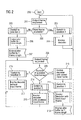
- FIG. 1 shows a decoding device in accordance with the invention
- FIG. 2 shows a flow diagram in order to illustrate a decoding method according to the invention
- FIG. 3 shows a cascaded decoding device.
- FIG. 1 shows a decoding device DE for decoding user data which is transmitted in data packets, e.g. IP packets.
- the user data can be audio data or voice data, for example, particularly in the context of real-time VoIP communication.
- the data packets, of which one data packet DP is illustrated by way of example in FIG. 1 are received via a packet-oriented communication network (not shown) such as the Internet, for example, and are therefore subject to certain propagation-time fluctuations.
- a jitter buffer JB which is connected in advance of the decoding device DE as an input buffer storage.
- Data packets which are received from the communication network are temporarily stored in the jitter buffer JB and can be read out by the decoding device DE.
- the decoding device DE features a user data output OUTPUT, via which the decoded user data is output.
- the decoding device DE implements a so-called hierarchical or scalable coding method in which a time domain coding method, e.g. in accordance with a CELP method, is combined with a frequency domain coding method, e.g. the TDAC method.
- the relevant frequency domain coding method builds hierarchically on the relevant time domain coding method insofar as a decoding result of the time domain coding method is refined by a decoding result of the frequency domain coding method.
- the coding result of the time domain coding method can be used without said result being refined by the frequency domain coding method, subject to slight quality losses.
- the decoding device DE features a decoder DEC 1 which implements a CELP time domain coding method and a decoder DEC 2 which implements the TDAC frequency domain coding method.
- the decoder DEC 1 which operates in accordance with the CELP method makes use of broadband expansion techniques in the time domain and features a decoder-based algorithmic delay of e.g. 29 ms.
- a decoder-based delay of a relevant decoder DEC 1 or DEC 2 is understood to mean the delay by which user data that is decoded by the decoder is delayed relative to the user data that is supplied to this decoder DEC 1 or DEC 2 respectively.
- the decoder DEC 2 which operates according to the TDAC method performs a Fourier transformation of the respective supplied user data and makes use of the so-called overlap-add method.
- the decoder DEC 2 is therefore a so-called transform decoder.
- the data packet DP contains coded user data comprising base data BDAT which is coded according to the CELP method and refining data RDAT which is coded according to the TDAC method.
- the refining data RDAT builds on the base data BDAT in the sense of a hierarchical coding.
- the base data BDAT is supplied to the decoder DEC 1 and the refining data RDAT is supplied to the decoder DEC 2 . Both decoders DEC 1 and DEC 2 decode the respectively supplied user data BDAT or RDAT in parallel operation.
- the decoder DEC 1 can decode the base data BDAT which is contained in the data packet DP independently of base data which is contained in other data packets, the decoding of the refining data RDAT of the data packet DP additionally requires refining data of the subsequent data packet.
- the decoder-based delay of the decoder DEC 2 is longer than the decoder-based delay of the decoder DEC 1 by the frame length of a data packet, e.g. 20 ms.
- Such a hierarchical arrangement of a CELP-based decoder, DEC 1 in this case, and a TDAC-based decoder, DEC 2 in this case, is currently being discussed in the context of the ITU-T recommendation G.729EV.
- the relatively long delay of the decoder DEC 2 would have a negative effect on the frame error rate of VoIP applications, since these applications only wait a predetermined time for a data packet containing coded user data and interpret an unsuccessful expiry of this maximal wait time as a packet loss. Decoders having a longer algorithmic delay result in a higher packet loss rate in networks which are subject to propagation-time fluctuations.
- the invention makes it possible in many cases nonetheless to output a user signal which is based on the base data and is of acceptable quality. Moreover, refining data which arrives too late can still be used in many cases to decode refining data which arrives subsequently and thus to limit any possible quality loss to one frame length.
- a buffer storage DB 1 whose input is coupled to an output of the decoder DEC 1 .
- the buffer storage DB 1 delays the base data BDAT, which was decoded in the decoder DEC 1 , by the difference between the decoder-related delays of the decoders DEC 1 and DEC 2 , i.e. by a frame length of the data packet DP (20 ms in this case).
- the output of the buffer storage DB 1 and an output of the decoder DEC 2 are coupled to a mixing device MIX for mixing the decoded base data BDAT, which has been delayed by the buffer storage DB 1 , and the decoded refining data RDAT from the decoder DEC 2 .
- a mixing device MIX for mixing the decoded base data BDAT, which has been delayed by the buffer storage DB 1 , and the decoded refining data RDAT from the decoder DEC 2 .
- the resulting mixed data is output as the decoded user data.
- the decoder DEC 1 can decode the Nth data packet immediately
- the decoder DEC 2 can only decode the N-1th data packet on the basis of the Nth data packet. If the Nth data packet does not arrive at the appropriate time but is delayed by no more than one frame length (20 ms in this case), this Nth data packet which arrives too late can still be decoded at the appropriate time and output by the decoder DEC 1 .
- the decoding device DE features an availability detector AD.
- the availability detector AD checks whether a relevant data packet DP and therefore the refining data RDAT is available at the appropriate time, i.e. in accordance with a time parameter.
- a time parameter can be predetermined e.g. by real-time requirements of a VoIP application.
- the availability detector AD is coupled to a switch device SW which has three switch positions 1 , 2 and 3 . Depending on the switch position 1 , 2 or 3 , different signals of the decoding device DE are switched through to the user data output OUTPUT.
- the switch position 1 , 2 or 3 that is to be assumed in each case is controlled by the availability detector AD depending on the availability of the relevant data packet DP or the refining data RDAT.
- the switch device SW connection interface which is assigned to the switch position 1 receives the resulting mixed data of the mixing device MIX.
- the switch device SW connection interface which is assigned to the switch position 3 is directly coupled to the output of the decoder DEC 1 .
- the switch device SW connection interface which is assigned to the switch position 2 is coupled to the output of the decoder DEC 1 via a buffer storage DB 2 .
- the base data BDAT which has been decoded by the decoder DEC 1 is delayed in the buffer storage DB 2 by one frame length, i.e. 20 ms in this case.
- the availability detector AD checks whether the refining data RDAT or the data packet DP is available at the appropriate time. If this is the case, i.e. following a positive check result, the switch device SW is set to the switch position 1 , wherein the switch device SW switches the mixed data through to the user data output OUTPUT. If the refining data RDAT is not available at the appropriate time, i.e. following a negative check result, the switch device SW is set to the switch position 2 or 3 . In the switch position 3 , the switch device SW switches the base data BDAT which is decoded by the decoder DEC 1 through to the user data output OUTPUT. In the switch position 2 , the switch device SW switches the base data BDAT which has been decoded by the decoder DEC 1 and additionally delayed by the buffer storage DB 2 through to the user data output OUTPUT.
- FIG. 2 shows a flow diagram in order to illustrate the method steps of the decoding method according to the invention.
- a method step 201 an output frame is requested at the user data output OUTPUT, e.g. by a VoIP application, with a specific time parameter.
- the availability detector AD checks whether an input frame, i.e. a data packet DP, is currently readable and therefore available in the jitter buffer JB. If this is the case, the switch device SW is moved into the switch position 1 in a method step 203 .
- the decoders DEC 1 and DEC 2 are then invoked, i.e. instructed, to decode the base data BDAT or refining data RDAT contained in the data packet DP which is read out from the jitter buffer JB. This is followed by a return to the method step 201 .
- the switch device SW is moved into the switch position 2 in a method step 205 and then an output frame is read out from the buffer storage DB 2 and output via the user data output OUTPUT.
- the jitter buffer JB is then extended by one frame length, i.e. by 20 ms in this case, such that an average delay of the jitter buffer JB increases by one frame length.
- a method step 208 an output frame is then requested again at the user data output OUTPUT.
- the availability detector AD checks how many input frames, i.e. data packets DP, are currently readable and therefore available in the jitter buffer JB. If no input frames are available, the switch device SW is moved into the switch position 3 in a method step 216 .
- the decoders DEC 1 and DEC 2 are then invoked without input frames. Since no data packet can be decoded in this case, a packet loss is assumed. In this case, known methods can be applied for bridging a user data gap that has occurred. Such methods are known as “frame erasure concealment”.
- the method step 217 is followed by a return to the method step 208 .
- the switch device SW is moved into the switch position 3 and the decoder DEC 1 is then invoked with the available base data BDAT of the input frame.
- the decoded base data BDAT is output directly via the user data output OUTPUT. This is followed by a return to the method step 208 .
- the decoders DEC 1 and DEC 2 are invoked with the oldest available input frame in a method step 210 , wherein the resulting decoding result is ignored.
- the switch device SW is then moved into the switch position 1 and the decoders DEC 1 and DEC 2 are invoked with the next input frame in a method step 212 .
- the switch position 1 the resulting mixed data of the decoders DEC 1 and DEC 2 is output via the user data output OUTPUT.
- the jitter buffer JB is then shortened by one frame length, i.e. 20 ms in this case, such that its average delay is reduced by one frame length. This is followed by a return to the method step 201 .
- the invention provides an acceptable fallback solution for cases in which data packets containing coded user data arrive too late and would be discarded according to the prior art.
- the invention offers an improvement in the decoding quality and rendition quality relative to decoding methods in which data packets that do not arrive at an appropriate time are discarded. According to the invention, if a data packet does not arrive at the appropriate time, in many cases it is possible at least to use the base data BDAT for generating an acceptable user signal.
- data packets which do not arrive at the appropriate time are not discarded but are instead routed to the decoding device DE for decoding.
- the late arriving refining data RDAT of a delayed data packet DP is routed to the decoder DEC 2 for decoding.
- this refining data RDAT can still be used to decode refining data from a subsequent data packet which arrives at the appropriate time. In this case, more refined quality of decoding is already possible for the subsequent data packet.
- the invention can be configured and developed in many diverse ways.
- the decoder DEC 2 can provide a particularly high-quality decoding given a correspondingly long decoder-related delay.
- provision can be made for detecting current real-time requirements of a communication application and, depending on said requirements, switching between the decoder DEC 2 and the decoder DEC 1 which has a shorter decoder-related delay.
- the decoders DEC 1 and DEC 2 can be implemented as decoders which are independent of each other.
- the decoder DEC 1 can be configured for decoding data packets having a frame length of 10 ms and the decoder DEC 2 for decoding data packets having a frame length of 20 ms in a wider frequency band.
- Such a cascaded decoding device is illustrated in FIG. 3 .
- FIG. 3 shows a data packet DPN containing base data DAT 1 and refining data DAT 2 , . . . , DATN which is in each case built hierarchically thereupon. Furthermore, provision is made for decoders DEC 1 , DEC 2 , . . . , DECN which are built hierarchically on each other and have different decoder-related delays. It is assumed that the decoder DEC 1 has a decoder-related delay DL 1 of 0 ms, the decoder DEC 2 has a decoder-related delay DL 2 of 10 ms and the decoder DECN has a decoder-related delay DLN of (N ⁇ 1)*10 ms accordingly.
- buffer storages DB 1 , DB 2 , . . . for at least partially equalizing the differences between the delays DL 1 , DL 2 , . . . , DLN as delay devices.
- the buffer storages DB 1 , DB 2 , . . . have a delay of 10 ms in each case.
- mixing devices MIX 2 , . . . , MIXN are coupled to an output of the decoders DEC 2 , . . . , DECN in each case.
- the coded user data which is contained in the data packet DPN is supplied to the decoders DEC 1 , DEC 2 , . . . , DECN, specifically the base data DAT 1 to the decoder DEC 1 , the refining data DAT 2 to the decoder DEC 2 and the refining data DATN to the decoder DECN accordingly.
- the decoder DEC 1 decodes the base data DAT 1 and outputs the decoded base data DAT 1 via a signal output OUTPUT_ 1 .
- the decoded base data DAT 1 is also temporarily stored in the buffer storage DB 1 , where it is delayed by 10 ms, and the delayed decoded base data DAT 1 is supplied to the mixing device MIX 2 .
- the refining data DAT 2 which is decoded by the decoder DEC 2 using the delay DL 2 is also supplied to the mixing device MIX 2 .
- the resulting mixed result is output by the mixing device MIX 2 via a signal output OUTPUT_ 2 and is also supplied to the buffer storage DB 2 .
- the buffer storage DB 2 delays the decoded refining data DAT 2 by 10 ms and, if applicable, supplies the delayed decoded refining data DAT 2 to a further mixing device which is arranged in a cascaded manner.
- the refining data DATN which was decoded by the decoder DECN using the delay DLN, and the decoded refining data which was delayed by a pre-connected buffer storage, are supplied to the mixing device MIXN.
- the resulting mixed result is output via a signal output OUTPUT_N.
- Successive refined decoded user data is consequently available at the signal outputs OUTPUT_ 1 , OUTPUT_ 2 , . . . , OUTPUT_N with various decoder-related delays.
- one of the signal outputs OUTPUT_ 1 , OUTPUT_ 2 , . . . , OUTPUT_N can be switched through to a user signal output of the decoding device.
Applications Claiming Priority (3)
| Application Number | Priority Date | Filing Date | Title |
|---|---|---|---|
| EP06006789.9 | 2006-03-30 | ||
| EP06006789 | 2006-03-30 | ||
| EP06006789.9A EP1841072B1 (de) | 2006-03-30 | 2006-03-30 | Verfahren und Einrichtung zum Dekodieren von schichtkodierten Daten |
Publications (2)
| Publication Number | Publication Date |
|---|---|
| US20070286276A1 US20070286276A1 (en) | 2007-12-13 |
| US8098727B2 true US8098727B2 (en) | 2012-01-17 |
Family
ID=36649106
Family Applications (1)
| Application Number | Title | Priority Date | Filing Date |
|---|---|---|---|
| US11/731,891 Expired - Fee Related US8098727B2 (en) | 2006-03-30 | 2007-03-30 | Method and decoding device for decoding coded user data |
Country Status (3)
| Country | Link |
|---|---|
| US (1) | US8098727B2 (zh) |
| EP (1) | EP1841072B1 (zh) |
| CN (1) | CN101051465B (zh) |
Cited By (1)
| Publication number | Priority date | Publication date | Assignee | Title |
|---|---|---|---|---|
| US9275650B2 (en) | 2010-06-14 | 2016-03-01 | Panasonic Corporation | Hybrid audio encoder and hybrid audio decoder which perform coding or decoding while switching between different codecs |
Families Citing this family (9)
| Publication number | Priority date | Publication date | Assignee | Title |
|---|---|---|---|---|
| US8411734B2 (en) | 2007-02-06 | 2013-04-02 | Microsoft Corporation | Scalable multi-thread video decoding |
| US9648325B2 (en) | 2007-06-30 | 2017-05-09 | Microsoft Technology Licensing, Llc | Video decoding implementations for a graphics processing unit |
| US8885729B2 (en) | 2010-12-13 | 2014-11-11 | Microsoft Corporation | Low-latency video decoding |
| US9706214B2 (en) | 2010-12-24 | 2017-07-11 | Microsoft Technology Licensing, Llc | Image and video decoding implementations |
| TWI501673B (zh) * | 2011-02-16 | 2015-09-21 | Amtran Technology Co Ltd | 無線音訊與視訊同步播放的方法及其播放系統 |
| RU2587467C2 (ru) | 2011-06-30 | 2016-06-20 | МАЙКРОСОФТ ТЕКНОЛОДЖИ ЛАЙСЕНСИНГ, ЭлЭлСи | Сокращение задержки при кодировании и декодировании видео |
| US8731067B2 (en) | 2011-08-31 | 2014-05-20 | Microsoft Corporation | Memory management for video decoding |
| US9819949B2 (en) | 2011-12-16 | 2017-11-14 | Microsoft Technology Licensing, Llc | Hardware-accelerated decoding of scalable video bitstreams |
| US10623305B1 (en) * | 2015-03-30 | 2020-04-14 | Amazon Technologies, Inc. | Contextual substitution of audiovisual application resources in response to unavailability |
Citations (13)
| Publication number | Priority date | Publication date | Assignee | Title |
|---|---|---|---|---|
| US20010036321A1 (en) * | 2000-04-27 | 2001-11-01 | Hiroki Kishi | Encoding apparatus and encoding method |
| US20020097807A1 (en) | 2001-01-19 | 2002-07-25 | Gerrits Andreas Johannes | Wideband signal transmission system |
| US6597750B1 (en) * | 1998-06-19 | 2003-07-22 | Thomson Licensing S.A. | Opposite polarization interference cancellation in satellite communication |
| US20040049376A1 (en) * | 2001-01-18 | 2004-03-11 | Ralph Sperschneider | Method and device for the generation of a scalable data stream and method and device for decoding a scalable data stream |
| WO2005066937A1 (ja) | 2004-01-08 | 2005-07-21 | Matsushita Electric Industrial Co., Ltd. | 信号復号化装置及び信号復号化方法 |
| US20050240414A1 (en) | 2002-04-25 | 2005-10-27 | Sony Corporation | Data processing system, data processing method, data processing device, and data processing program |
| WO2005106848A1 (ja) | 2004-04-30 | 2005-11-10 | Matsushita Electric Industrial Co., Ltd. | スケーラブル復号化装置および拡張レイヤ消失隠蔽方法 |
| US6980143B2 (en) * | 2002-01-10 | 2005-12-27 | Fraunhofer-Gesellschaft Zur Foerderung Der Angewandten Forschung Ev | Scalable encoder and decoder for scaled stream |
| US20070208557A1 (en) * | 2006-03-03 | 2007-09-06 | Microsoft Corporation | Perceptual, scalable audio compression |
| US20070253481A1 (en) * | 2004-10-13 | 2007-11-01 | Matsushita Electric Industrial Co., Ltd. | Scalable Encoder, Scalable Decoder,and Scalable Encoding Method |
| US7321851B2 (en) | 1999-12-28 | 2008-01-22 | Global Ip Solutions (Gips) Ab | Method and arrangement in a communication system |
| US7496517B2 (en) * | 2001-01-18 | 2009-02-24 | Fraunhofer-Gesellschaft Zur Foerderung Der Angewandten Forschung E.V. | Method and device for generating a scalable data stream and method and device for decoding a scalable data stream with provision for a bit saving bank function |
| US7516230B2 (en) * | 2001-01-18 | 2009-04-07 | Fraunhofer-Gesellschaft Zur Foerderung Der Angewandten Forschung E.V. | Method and device for the generation or decoding of a scalable data stream with provision for a bit-store, encoder and scalable encoder |
-
2006
- 2006-03-30 EP EP06006789.9A patent/EP1841072B1/de not_active Expired - Fee Related
-
2007
- 2007-03-30 CN CN2007100921853A patent/CN101051465B/zh not_active Expired - Fee Related
- 2007-03-30 US US11/731,891 patent/US8098727B2/en not_active Expired - Fee Related
Patent Citations (14)
| Publication number | Priority date | Publication date | Assignee | Title |
|---|---|---|---|---|
| US6597750B1 (en) * | 1998-06-19 | 2003-07-22 | Thomson Licensing S.A. | Opposite polarization interference cancellation in satellite communication |
| US7321851B2 (en) | 1999-12-28 | 2008-01-22 | Global Ip Solutions (Gips) Ab | Method and arrangement in a communication system |
| US20010036321A1 (en) * | 2000-04-27 | 2001-11-01 | Hiroki Kishi | Encoding apparatus and encoding method |
| US6993198B2 (en) * | 2000-04-27 | 2006-01-31 | Canon Kabushiki Kaisha | Encoding apparatus and encoding method |
| US20040049376A1 (en) * | 2001-01-18 | 2004-03-11 | Ralph Sperschneider | Method and device for the generation of a scalable data stream and method and device for decoding a scalable data stream |
| US7516230B2 (en) * | 2001-01-18 | 2009-04-07 | Fraunhofer-Gesellschaft Zur Foerderung Der Angewandten Forschung E.V. | Method and device for the generation or decoding of a scalable data stream with provision for a bit-store, encoder and scalable encoder |
| US7496517B2 (en) * | 2001-01-18 | 2009-02-24 | Fraunhofer-Gesellschaft Zur Foerderung Der Angewandten Forschung E.V. | Method and device for generating a scalable data stream and method and device for decoding a scalable data stream with provision for a bit saving bank function |
| US20020097807A1 (en) | 2001-01-19 | 2002-07-25 | Gerrits Andreas Johannes | Wideband signal transmission system |
| US6980143B2 (en) * | 2002-01-10 | 2005-12-27 | Fraunhofer-Gesellschaft Zur Foerderung Der Angewandten Forschung Ev | Scalable encoder and decoder for scaled stream |
| US20050240414A1 (en) | 2002-04-25 | 2005-10-27 | Sony Corporation | Data processing system, data processing method, data processing device, and data processing program |
| WO2005066937A1 (ja) | 2004-01-08 | 2005-07-21 | Matsushita Electric Industrial Co., Ltd. | 信号復号化装置及び信号復号化方法 |
| WO2005106848A1 (ja) | 2004-04-30 | 2005-11-10 | Matsushita Electric Industrial Co., Ltd. | スケーラブル復号化装置および拡張レイヤ消失隠蔽方法 |
| US20070253481A1 (en) * | 2004-10-13 | 2007-11-01 | Matsushita Electric Industrial Co., Ltd. | Scalable Encoder, Scalable Decoder,and Scalable Encoding Method |
| US20070208557A1 (en) * | 2006-03-03 | 2007-09-06 | Microsoft Corporation | Perceptual, scalable audio compression |
Non-Patent Citations (10)
| Title |
|---|
| Channel Adaptive Prioritized Transmission of Layered Video over Wireless LAN by Yingwei Chen, Caries Ruiz Floriach, Jung Chul Ye and Kiran Challapali The 14th IEEE 2003 International Symposium on Personal, Indoor and Mobile Radio Communication Proceedings. |
| Chen Yingwei et al., "Channel Adaptive Prioritized Transmission of Layered Video Over Wireless LAN", Personal, Indoor and Mobile Radio Communications, 2003, PIMRC 2003, 14th IEEE Proceedings on Sep. 7-10, 2003, Piscataway, NJ, USA, IEEE vol. 2, Septmber 7, 2003, pp. 2948-2952, XP010678566, Abstract. |
| H. Dong, et. al, "Speech Coding for Mobile Ad Hoc Networks", Institute of Electrical and Electronics Engineers, Conference Record of the 37th Asilomar Conference on Signals, Systems, & Computers, Pacific Groove, CA, Nov. 9-12, 2003, Asilomar Conference on Signals, Systems & Computers, NY, NY, IEEE, US, vol. 1 of 2, Conf. 37, Nov. 9, 2003, pp. 280-284, XP010701700. |
| H. Taddei et al., "A Scalable Three Bit-Rates 8-14.1-24 KGIT/S Audio Coder Codeur udio Hierarchique (8-14, 1-24 KTIB/S)", Annales Des Telecommunications-Annals of Telecommunications, Get Lavoisier, Paris, FR, vol. 55, No. 9/10, Sep. 2000, pp. 483-492, XP000968161. |
| M. Zink et. al, "P2P Streaming Using Multiple Description Coded Video", EUROMICRO Conference, 2004, Proceedings 30th Rennes, France, Aug. 31-Sep. 3, 2004, Piscataway, NJ, USA, IEEE, Aug. 31, 2004, pp. 240-247, XP010723597. |
| P. Cuenca et al., "Packing Scheme for Layered Coding MPEG-2 Video Transmission Over ATM Based Networks", IEEE ATM Workshop 1997, Proceedings LISBOA, Portugal, May 25-28, 1997, New York, NY, USA, IEEE, US, May 25, 1997, pp. 168-177, XP010247401, Abstract. |
| P2P Streaming Using Multiple Description Coded Video by Michael Zink and Andreas Mauthe, Proceedings of the 30th Euromicro Conference. |
| Speech Coding for Mobile Ad Hoc Networks by H. Don, I. D. Chakares, C. H. Lin, A. Gersho, E. Belding-Royer, U. Madhow, J. D. Gibson, Conference Record of the 37th Asilomar Conference on Signals, Systems & Computers, Pacific Groove, CA. |
| Switched Error Concealment and Robust Coding Decisions in Scalable Video Coding by Rui Zhang, Shankar L. Regunathan and Kenneth Rose, Image Processing. |
| Zhang Rui et al., "Switched Error Concealment and Robust Coding Decisions in Scalablevideo Coding", Image processing, 2000, Proceedings, 2000 International Conference on Sep. 10-13, 2000, Piscataway, NJ, USA, IEEE, vol. 3, 10, Sep. 2000, pp. 380-383, XP010529483, Abstract. |
Cited By (1)
| Publication number | Priority date | Publication date | Assignee | Title |
|---|---|---|---|---|
| US9275650B2 (en) | 2010-06-14 | 2016-03-01 | Panasonic Corporation | Hybrid audio encoder and hybrid audio decoder which perform coding or decoding while switching between different codecs |
Also Published As
| Publication number | Publication date |
|---|---|
| EP1841072B1 (de) | 2016-06-01 |
| US20070286276A1 (en) | 2007-12-13 |
| EP1841072A1 (de) | 2007-10-03 |
| CN101051465A (zh) | 2007-10-10 |
| CN101051465B (zh) | 2011-06-15 |
Similar Documents
| Publication | Publication Date | Title |
|---|---|---|
| US8098727B2 (en) | Method and decoding device for decoding coded user data | |
| Janssen et al. | Assessing voice quality in packet-based telephony | |
| KR101121212B1 (ko) | 통신 시스템에서 데이터 전송 방법 | |
| US20020105951A1 (en) | Playback of streamed media | |
| JP5528811B2 (ja) | 効率的なメディアの扱いのための受信機の動作及び実装 | |
| US20080159384A1 (en) | System and method for jitter buffer reduction in scalable coding | |
| US20070263672A1 (en) | Adaptive jitter management control in decoder | |
| JP2006238445A (ja) | 仮想ジッタ・バッファおよび時間スケール修正を使用した、VoiceoverIP通信ネットワークにおいてネットワーク・ジッタを処理する方法および装置 | |
| US8898060B2 (en) | Source code adaption based on communication link quality and source coding delay | |
| EP2276023A2 (en) | Efficient speech stream conversion | |
| US8787490B2 (en) | Transmitting data in a communication system | |
| EP2461322A1 (en) | Transcoding method device apparatus and system | |
| TW200917764A (en) | System and method for providing AMR-WB DTX synchronization | |
| KR101002405B1 (ko) | 오디오 신호의 타임-스케일링 제어 | |
| US20090043567A1 (en) | Variable frame offset coding | |
| US7773633B2 (en) | Apparatus and method of processing bitstream of embedded codec which is received in units of packets | |
| JP2001016584A (ja) | ビデオ伝送方法および装置 | |
| EP2200025B1 (en) | Bandwidth scalable codec and control method thereof | |
| US20070186146A1 (en) | Time-scaling an audio signal | |
| US20220392459A1 (en) | Audio packet loss concealment via packet replication at decoder input | |
| Maheswari et al. | Performance evaluation of packet loss replacement using repetititon technique in voip streams | |
| Maheswari et al. | Receiver based packet loss replacement technique for high quality VoIP streams | |
| KR20070061269A (ko) | 패킷 단위로 수신된 임베디드 코덱의 비트 스트림 처리장치 및 방법 |
Legal Events
| Date | Code | Title | Description |
|---|---|---|---|
| AS | Assignment |
Owner name: SIEMENS AKTIENGESELLSCHAFT, GERMANY Free format text: ASSIGNMENT OF ASSIGNORS INTEREST;ASSIGNORS:GARTNER, MARTIN;TADDEI, HERVE;REEL/FRAME:019513/0804;SIGNING DATES FROM 20070216 TO 20070320 Owner name: SIEMENS AKTIENGESELLSCHAFT, GERMANY Free format text: ASSIGNMENT OF ASSIGNORS INTEREST;ASSIGNORS:GARTNER, MARTIN;TADDEI, HERVE;SIGNING DATES FROM 20070216 TO 20070320;REEL/FRAME:019513/0804 |
|
| ZAAA | Notice of allowance and fees due |
Free format text: ORIGINAL CODE: NOA |
|
| ZAAB | Notice of allowance mailed |
Free format text: ORIGINAL CODE: MN/=. |
|
| AS | Assignment |
Owner name: SIEMENS ENTERPRISE COMMUNICATIONS GMBH & CO. KG, G Free format text: ASSIGNMENT OF ASSIGNORS INTEREST;ASSIGNOR:SIEMENS AKTIENGESELLSCHAFT;REEL/FRAME:027295/0392 Effective date: 20091009 |
|
| STCF | Information on status: patent grant |
Free format text: PATENTED CASE |
|
| AS | Assignment |
Owner name: UNIFY GMBH & CO. KG, GERMANY Free format text: CHANGE OF NAME;ASSIGNOR:SIEMENS ENTERPRISE COMMUNICATIONS GMBH & CO. KG;REEL/FRAME:033156/0114 Effective date: 20131021 |
|
| FPAY | Fee payment |
Year of fee payment: 4 |
|
| MAFP | Maintenance fee payment |
Free format text: PAYMENT OF MAINTENANCE FEE, 8TH YEAR, LARGE ENTITY (ORIGINAL EVENT CODE: M1552); ENTITY STATUS OF PATENT OWNER: LARGE ENTITY Year of fee payment: 8 |
|
| AS | Assignment |
Owner name: RINGCENTRAL IP HOLDINGS, INC., CALIFORNIA Free format text: ASSIGNMENT OF ASSIGNORS INTEREST;ASSIGNORS:UNIFY SOFTWARE AND SOLUTIONS GMBH & CO. KG;UNIFY PATENTE GMBH & CO. KG;REEL/FRAME:053342/0187 Effective date: 20191230 Owner name: RINGCENTRAL, INC., CALIFORNIA Free format text: ASSIGNMENT OF ASSIGNORS INTEREST;ASSIGNOR:RINGCENTRAL IP HOLDINGS, INC.;REEL/FRAME:053342/0217 Effective date: 20200702 |
|
| AS | Assignment |
Owner name: UNIFY PATENTE GMBH & CO. KG, GERMANY Free format text: CONFIDENTIAL PATENT AGREEMENT;ASSIGNOR:UNIFY GMBH & CO. KG;REEL/FRAME:054822/0001 Effective date: 20140930 |
|
| AS | Assignment |
Owner name: RINGCENTRAL, INC., CALIFORNIA Free format text: ASSIGNMENT OF ASSIGNORS INTEREST;ASSIGNOR:RINGCENTRAL IP HOLDINGS, INC.;REEL/FRAME:058855/0785 Effective date: 20220106 |
|
| AS | Assignment |
Owner name: BANK OF AMERICA, N.A., AS COLLATERAL AGENT, NORTH CAROLINA Free format text: SECURITY INTEREST;ASSIGNOR:RINGCENTRAL, INC.;REEL/FRAME:062973/0194 Effective date: 20230214 |
|
| FEPP | Fee payment procedure |
Free format text: MAINTENANCE FEE REMINDER MAILED (ORIGINAL EVENT CODE: REM.); ENTITY STATUS OF PATENT OWNER: LARGE ENTITY |
|
| LAPS | Lapse for failure to pay maintenance fees |
Free format text: PATENT EXPIRED FOR FAILURE TO PAY MAINTENANCE FEES (ORIGINAL EVENT CODE: EXP.); ENTITY STATUS OF PATENT OWNER: LARGE ENTITY |
|
| STCH | Information on status: patent discontinuation |
Free format text: PATENT EXPIRED DUE TO NONPAYMENT OF MAINTENANCE FEES UNDER 37 CFR 1.362 |
|
| FP | Lapsed due to failure to pay maintenance fee |
Effective date: 20240117 |