US809802A - Variable-speed mechanism. - Google Patents
Variable-speed mechanism. Download PDFInfo
- Publication number
- US809802A US809802A US21225204A US1904212252A US809802A US 809802 A US809802 A US 809802A US 21225204 A US21225204 A US 21225204A US 1904212252 A US1904212252 A US 1904212252A US 809802 A US809802 A US 809802A
- Authority
- US
- United States
- Prior art keywords
- pulley
- head
- sliding
- heads
- shaft
- Prior art date
- Legal status (The legal status is an assumption and is not a legal conclusion. Google has not performed a legal analysis and makes no representation as to the accuracy of the status listed.)
- Expired - Lifetime
Links
Images


Classifications
-
- F—MECHANICAL ENGINEERING; LIGHTING; HEATING; WEAPONS; BLASTING
- F16—ENGINEERING ELEMENTS AND UNITS; GENERAL MEASURES FOR PRODUCING AND MAINTAINING EFFECTIVE FUNCTIONING OF MACHINES OR INSTALLATIONS; THERMAL INSULATION IN GENERAL
- F16H—GEARING
- F16H9/00—Gearings for conveying rotary motion with variable gear ratio, or for reversing rotary motion, by endless flexible members
- F16H9/02—Gearings for conveying rotary motion with variable gear ratio, or for reversing rotary motion, by endless flexible members without members having orbital motion
- F16H9/04—Gearings for conveying rotary motion with variable gear ratio, or for reversing rotary motion, by endless flexible members without members having orbital motion using belts, V-belts, or ropes
- F16H9/10—Gearings for conveying rotary motion with variable gear ratio, or for reversing rotary motion, by endless flexible members without members having orbital motion using belts, V-belts, or ropes engaging a pulley provided with radially-actuatable elements carrying the belt
Definitions
- the invention consists generally in providing an improved mechanism for expanding and contracting the pulleys forming part of the variable-speed mechanism.
- the invention consists in provid-' ing means for tightening the belt, if desired, and also equalize the tension when the pulleys are of equal or unequal diameter.
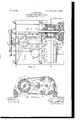
- Figure 1 is a plan view of a variable-speed mechanism embodying my invention.
- Fig. 2 is a similar view showing one of the pulleys in section and the shifter-lever moved to the left of the position shown in Fig. 1.
- Fig. 3 is atransverse sectional view on the line .1; a; of Fig. 2.
- Fig. A is a sectional view showing in detail the belttightening mechanism.
- Fig. 5 is a transverse sectional view on the line y y of Fig. 1.
- Fig. 6 is a detail view showing the manner of securing the pulley staves or plates on the conical heads thereof.
- 2 represents a suitable frame whereon a master or drive shaft 3, operated from a suitable source of power, is mounted.
- a second shaft t is also mounted on said frame parallel with the shaft 3 and provided with a pulley 5, from which power is transmitted to the machine or other mechanism to be operated.
- the expansible pulleys which I will now proceed to describe, are mounted.
- These pulleys are substantially the same in construction, though mounted on their shafts in different ways, and a description of one will suflice for the other.
- the pulley on the shaft 3 comprises conical heads or ends 6 and 7, that are splined on the shaft to slide freely lengthwise thereof.
- Eachhead is provided with a series of radiating slots 8, adapted to receive lugs 9, provided on the ends of staves 10, that are fitted between the heads of the pulley and have beveled ends to slide over the conical surfaces of the heads.
- Screws 11 are provided in said lugs, and thin sheet-metal plates 12, preferably of a spring material, are provided on said screws and arranged to bear on the surfaces of the heads and hold the pulley-staves in place between them, though allowing said staves to slide freely in said slots 8 to permit the expansion and contraction of the pulley.
- the pulley-heads 6 and 7 are therefore capable of moving back and forth on said shaft toward or from each other and expand or contract the pulley, but cannot revolve independently of the shaft on which they are mounted.
- the other pulley on the shaft 4 is, as I have already explained, of substantially the same construction, and I will therefore refer to the corresponding parts by the same referencenumerals, giving them a prime-marl; to prevent confusion in the subsequentdescription
- a sleeve 13 is provided on the shaft 4:, upon which the pulley-heads 6 and 7 are splined.
- the head 6 is provided with gears 14, arranged to mesh with an internal gear 15, mounted on the hub 16 of a loose pulley 17, that is connected by a belt 19 with the pulley 18, secured on the shaft 3.
- the gears 1 1 also mesh with a pinion 20, secured on the shaft 4, as shown in Fig. 2.
- the arrangement of the internal gear is substantially thesame as that shown and described in the Letters Patent above referred to, and I makeno claim to the same herein.
- the head 6 is held against movement longitudinally on the shaft a by the pinion 20 and the sleeve 13, while the head 7 is free to slide back and forthon the sleeve 13 toward or from the head 6 for the purpose of increasing or decreasing the diameter of the pulley.
- a sleeve 23 is loosely mounted on the rod 21 and carries an arm 2a, that engages the head 7.
- a sleeve 25 is also mounted on. the rod 21 and provided with a stud 26, whereon a cam-disk 27 is mounted. The edge of the cam bears on the end of the sleeve 23 to slide the same along said rod and press in the pulley-head 7" to expand the pulley.
- the end of the rod 21 is threaded and provided with an interiorly-threaded sleeve 28, whose inner end also bears on the edge of the camdisk.
- This sleeve 28 is mounted in a bearing 29 and is provided with a loosely-mounted hub 30, carrying a gear 31 and a hand-wheel 32.
- a set-screw 33 in said hub enters a slot 34, extending lengthwise of the sleeve 28, and
- a plate 35 is mounted on the bearing 29 and provided with a hooked end 36, that enters an annular groove in the hub 30 and prevents it from slipping off the end of the sleeve 28.
- a shifter-lever 37 is pivoted at one end on a bar 38 and mounted on the stud 26. Movement of this lever back and forth will slide the sleeve 25 on the shaft 21 and through the mechanism hereinafter described rotate the cam and operate the pulley-expanding mecl anism.
- the cam 27 is provided with a gear 38, that meshes with the teeth of a rack 39 on a frame 40, that is supported upon parallel rods 41 in the machine-frame. These rods are threaded at one end, as shown, to receive correspondingly-threaded bearings of the frame 40, and revolution of said rods ,will cause a reciprocating movement of said frame and a corresponding movementpf the cam-disk toward or from the pulley.
- the sleeve 23 is provided with a rack-bar 42, that engages a gear 43, provided on a second cam-disk 44, that is supported on an arm 45 of the frame 40.
- This cam 44 is arranged to engage the hub 46 of the pulley-head 7 and move the same toward the opposite pulley-head when the shifter-lever is actuated.
- the gears 47 mounted on the ends of the rods 41, engage the teeth of the gear 31 and are revolved thereby when the handwheel 32 is operated.
- the operation of the mechanism for expanding and contracting the pulleys is as follows: The operator desiring to change the speed of the shaft 4 and the machine connected therewith will grasp the shifter-lever and assuming, as shown in Fig. 2, that he desires to contractthe pulley shown in section and expand the other one he will throw the shifterlever toward the left. This will have the eifect of releasing the pulley-head 7 and allowing the tension of the belt to contract the staves and reduce the diameter of the pulley, while the head 7 will bear on the edge of the cam 44 and move away from the opposite pulley-head 6.
- the operator will grasp the hand-wheel 32, revolve the rods 41, and move the frame 40 and the entire cam mechanism a suflicient distance to expand both pulleys and tighten the belt.
- the frame 40 can be moved slightly to allow sufiicient contraction of the pulleys to produce the desired belt tension.
- a second shaft a second expansible pulley having a sliding and a non-sliding head, a belt connecting said pulleys, and an arm engaging one of the sliding heads of said first-named 5 pulley, means engaging the other sliding head of said first-named pulley and the sliding head of the second pulley to move them toward their opposite heads to expand said secondnamed pulley and also move said arm to allow 3 the tension of the belt to separate the heads of said first-named pulley and contract it, substantially as described.
Landscapes
- Engineering & Computer Science (AREA)
- General Engineering & Computer Science (AREA)
- Mechanical Engineering (AREA)
- Transmissions By Endless Flexible Members (AREA)
Description
No. 809,802. PATENTEDJAN. 9, 1906; S. L. HEYWOOD.
VARIABLE SPEED MECHANISM.
APPLICATION FILED JUNE 13, 1904.
B SHEETS-SHEET l.
INVE/IT R' L175 LJ/EYA No. 809,802. PATENTED JAN. 9, 1906. S. L. HEYWOOD. VARIABLE SPEED MECHANISM.
APPLICATION FILED JUNE 13, 1904.
[WT/75555.5 74 m 7 PATENTED JAN. 9, 1906.
S. L. HEYWOOD.
VARIABLE SPEED MECHANISM.
APPLICATION FILED JUNE 13, 1904.
3 SHEETS-SHEET 3.
UNITE STATES PATENT @FFTQE.
VARIABLE-SPEED MECHANISM- Specification of Letters Patent.
Patented Jan. 9, 1906.
Application filed June 13, 1904. Serial No. 212,252.
and described in Letters Patent of the United States issued to me December 11, 1894, No. 530,588, and April 27, 1897, No. 581,286.
The invention consists generally in providing an improved mechanism for expanding and contracting the pulleys forming part of the variable-speed mechanism.
Further, the invention consists in provid-' ing means for tightening the belt, if desired, and also equalize the tension when the pulleys are of equal or unequal diameter.
Further, the invention consists in various constructions and combinations, all as hereinafter described, and particularly pointed out in the claims.
In the accompanying drawings, forming part of this specification, Figure 1 is a plan view of a variable-speed mechanism embodying my invention. Fig. 2 is a similar view showing one of the pulleys in section and the shifter-lever moved to the left of the position shown in Fig. 1. Fig. 3 is atransverse sectional view on the line .1; a; of Fig. 2. Fig. A is a sectional view showing in detail the belttightening mechanism. Fig. 5 is a transverse sectional view on the line y y of Fig. 1. Fig. 6 is a detail view showing the manner of securing the pulley staves or plates on the conical heads thereof.
In the drawings, 2 represents a suitable frame whereon a master or drive shaft 3, operated from a suitable source of power, is mounted. A second shaft t is also mounted on said frame parallel with the shaft 3 and provided with a pulley 5, from which power is transmitted to the machine or other mechanism to be operated. Upon these two shafts 3 and I the expansible pulleys, which I will now proceed to describe, are mounted. These pulleys are substantially the same in construction, though mounted on their shafts in different ways, and a description of one will suflice for the other. The pulley on the shaft 3 comprises conical heads or ends 6 and 7, that are splined on the shaft to slide freely lengthwise thereof. Eachhead is provided with a series of radiating slots 8, adapted to receive lugs 9, provided on the ends of staves 10, that are fitted between the heads of the pulley and have beveled ends to slide over the conical surfaces of the heads. Screws 11 are provided in said lugs, and thin sheet-metal plates 12, preferably of a spring material, are provided on said screws and arranged to bear on the surfaces of the heads and hold the pulley-staves in place between them, though allowing said staves to slide freely in said slots 8 to permit the expansion and contraction of the pulley. The pulley-heads 6 and 7 are therefore capable of moving back and forth on said shaft toward or from each other and expand or contract the pulley, but cannot revolve independently of the shaft on which they are mounted. The other pulley on the shaft 4 is, as I have already explained, of substantially the same construction, and I will therefore refer to the corresponding parts by the same referencenumerals, giving them a prime-marl; to prevent confusion in the subsequentdescription.
A sleeve 13 is provided on the shaft 4:, upon which the pulley-heads 6 and 7 are splined. The head 6 is provided with gears 14, arranged to mesh with an internal gear 15, mounted on the hub 16 of a loose pulley 17, that is connected by a belt 19 with the pulley 18, secured on the shaft 3. The gears 1 1 also mesh with a pinion 20, secured on the shaft 4, as shown in Fig. 2. The arrangement of the internal gear is substantially thesame as that shown and described in the Letters Patent above referred to, and I makeno claim to the same herein. The head 6 is held against movement longitudinally on the shaft a by the pinion 20 and the sleeve 13, while the head 7 is free to slide back and forthon the sleeve 13 toward or from the head 6 for the purpose of increasing or decreasing the diameter of the pulley.
Between the shafts 3 and 4 I arrange a rod 21, whereon an arm 22, having a forked end to straddle the shaft 3 and engage the head 6, is secured. A sleeve 23 is loosely mounted on the rod 21 and carries an arm 2a, that engages the head 7. A sleeve 25 is also mounted on. the rod 21 and provided with a stud 26, whereon a cam-disk 27 is mounted. The edge of the cam bears on the end of the sleeve 23 to slide the same along said rod and press in the pulley-head 7" to expand the pulley. The end of the rod 21 is threaded and provided with an interiorly-threaded sleeve 28, whose inner end also bears on the edge of the camdisk. This sleeve 28 is mounted in a bearing 29 and is provided with a loosely-mounted hub 30, carrying a gear 31 and a hand-wheel 32. A set-screw 33 in said hub enters a slot 34, extending lengthwise of the sleeve 28, and
prevents the revolution of the hand-wheel 32' or said sleeve independently of the shaft, but allows the sleeve and the rod 21 to be moved lengthwise independently of the hub and the hand-wheel 32.
A plate 35 is mounted on the bearing 29 and provided with a hooked end 36, that enters an annular groove in the hub 30 and prevents it from slipping off the end of the sleeve 28. A shifter-lever 37 is pivoted at one end on a bar 38 and mounted on the stud 26. Movement of this lever back and forth will slide the sleeve 25 on the shaft 21 and through the mechanism hereinafter described rotate the cam and operate the pulley-expanding mecl anism.
The cam 27 is provided with a gear 38, that meshes with the teeth of a rack 39 on a frame 40, that is supported upon parallel rods 41 in the machine-frame. These rods are threaded at one end, as shown, to receive correspondingly-threaded bearings of the frame 40, and revolution of said rods ,will cause a reciprocating movement of said frame and a corresponding movementpf the cam-disk toward or from the pulley. The sleeve 23 is provided with a rack-bar 42, that engages a gear 43, provided on a second cam-disk 44, that is supported on an arm 45 of the frame 40. This cam 44 is arranged to engage the hub 46 of the pulley-head 7 and move the same toward the opposite pulley-head when the shifter-lever is actuated. The gears 47, mounted on the ends of the rods 41, engage the teeth of the gear 31 and are revolved thereby when the handwheel 32 is operated.
The operation of the mechanism for expanding and contracting the pulleys is as follows: The operator desiring to change the speed of the shaft 4 and the machine connected therewith will grasp the shifter-lever and assuming, as shown in Fig. 2, that he desires to contractthe pulley shown in section and expand the other one he will throw the shifterlever toward the left. This will have the eifect of releasing the pulley-head 7 and allowing the tension of the belt to contract the staves and reduce the diameter of the pulley, while the head 7 will bear on the edge of the cam 44 and move away from the opposite pulley-head 6. The movement of the cam-disk 27 mounted on the loose sleeve 25, will, however, cause a greater movement of the pulleyhead 6 than the head 7, and consequently expand the pulley-staves between them and enlarge the diameter of the pulley sufficiently to take up the slack caused by the contraction of the opposite pulley. If it is desired to make the pulleys the same diameter, the shifter-lever is thrown to the position shown in Fig. 1 and the pressure of the arm 24 on the head 7 will force it in toward the opposite fixed head and expand the pulley-staves. The movement of the cam 27 to the position shown in Fig. 1 will cause a longitudinal movement of the rod 21 and allow the tension of the belt to press the heads 6 and 7 apart, and as the movement of the arm 22 and the head 6 will be faster than the movement of the head 7 a corresponding contraction or reduction in diameter of the pulley will take place. The longitudinal movement of the shaft 21 will be permitted, as will be noted from the preceding description, through the sliding connection between the sleeve 28 and the hub 30. If when the parts are in the position shown in Fig. 1 the shifter-lever 37 be moved toward the right, the head 7 will be moved toward the head 6 to expand that pulley and the head 7 will be released from pressure by the cam 44 to allow the tension of the belt to separate the heads 6 and 7 and contract that pulley. If after the shifter-lever has been adjusted in the desired position or when the cams have reached the limit of their movement it appears advisable to increase the tension of the belt, the operator will grasp the hand-wheel 32, revolve the rods 41, and move the frame 40 and the entire cam mechanism a suflicient distance to expand both pulleys and tighten the belt. On the other hand, if after the shifter-lever has been adjusted the belt appears too tight the frame 40 can be moved slightly to allow sufiicient contraction of the pulleys to produce the desired belt tension.
I claim as my invention 1. The combination, with two expansible pulleys one having sliding heads and the other a sliding and a non-sliding head, the sliding head of the latter pulley being free to recede from the other head by the tension of the belt to contract the pulley, of means for moving the heads of the former pulley in the same direction but at different speeds to expand that pulley.
2. The combination, with the expansible pulleys, one having sliding heads and the other a sliding and a non-sliding head, a belt connecting said pulleys, the sliding head of one pulley receding from its non-sliding head under tension of the belt to contract the pulley, of a cam mechanism arranged to move the heads of the other pulley in the same direction but at different speeds to expand that pulley.
3. The combination, with an expansible pulley having sliding heads, of a second ex pansible pulley having one sliding and one non-sliding head, a belt connecting said pulleys, and mechanism for expanding one pulley and allowing a corresponding contraction of the other, substantially as described.
ing head to recede under tension of the belt at a greater speed to contract the pulley.
5. The combination, with the expansible pulleys and a connecting-belt, of pivoted cams, mechanism arranged to rotate said cams and I 5 to contract one pulley and expand the other,
and mechanism for moving said cams without rotating them to contract or expand both of said pulleys simultaneously.
6. The combination, with a shaft, of an expansible pulley having sliding heads thereon,
a second shaft, a second expansible pulley having a sliding and a non-sliding head, a belt connecting said pulleys, and an arm engaging one of the sliding heads of said first-named 5 pulley, means engaging the other sliding head of said first-named pulley and the sliding head of the second pulley to move them toward their opposite heads to expand said secondnamed pulley and also move said arm to allow 3 the tension of the belt to separate the heads of said first-named pulley and contract it, substantially as described.
7. The combination, with a shaft, of an expansible pulley having sliding heads thereon,
55 a second shaft and a second expansible pulley having a sliding and a non-sliding head, a
belt connecting said pulleys, a longitudinallymovable rod provided with an arm arranged to engage one of the heads of said first- 4 named pulley, and mechanism for moving the opposite sliding head of said first-named pulley toward the other head and also moving said arm at a greater speed to release said other head and allow the contraction of said first-named pulley and also moving the sliding head of said second-named pulley toward its non-sliding head, substantially as described.
8. The combination, with a shaft, of an expansible pulley having sliding heads thereon,
S a second shaft and a second pulley having a sliding and a non-sliding head, a belt connectmg said pulleys, arms engaging one of the sliding heads of said first-named pulley and the sliding head of said second-named pulley upon opposite sides of their respective pulleys, and mechanism for moving said arms in the same direction to expand one pulley and contract the other.
9. The combination, with an expansible pulley having sliding heads, of a second expansible pulley having a sliding and a non-sliding head, a belt connecting said pulleys, means for movingthe sliding head on one pulley toward its non-sliding head to expand that pulley and allowing the separation ofthe sliding heads of the other pulley to contract it, and cam devices provided in connection with said moving means, substantially as described.
10. The combination, with a shaft, of an expansible pulley having sliding heads thereon, a second shaft and a second expansible pulley having a sliding and a non-sliding head, a belt connecting said pulleys, a longitudinally-movable rod provided with an arm engaging one of the sliding heads of said first-named pulley, a cam engaging the opposite head of the same pulley, an arm loosely mounted on said rod and engaging the sliding head of said secondnamed pulley, a sleeve having a longitudinal movement with said rod, a second cam arranged between and engaging said sleeve and looselymounted arm, and mechanism for rotating said cams simultaneously and to move said rod lengthwise to expand one pulley and contract the other.
11. The combination, with the expansible pulleys, one having two sliding heads and the other having a sliding and a non-sliding head, of a cam mechanism arranged to move one of the two sliding heads of one pulley toward the other head of the same pulley and allowing said other head to move in the same direction but at a greater rate of speed and also moving the one sliding head toward its nonsliding head, substantially as described.
12. The combination, with the expansible pulleys and a connecting-belt, of mechanism for moving the head of one pulley towardits opposite head to cause the expansion of that pulley and simultaneously moving both heads of the other pulley in the same direction but at different speeds to contract that pulley.
13. The combination of two expansible pul-' leys, one having sliding heads and the other asliding and non-sliding head, the sliding head of the latter pulley being free to recede from the other head through the tension of the belt to contract that pulley, of mechanism operating during a portion of its movement to move the heads of the former pulley in opposite directions to expand that pulley.
In witness whereof I have hereunto set my hand this 9th day of June, 1904.
SILAS L. HEYl/VOOD.
In presence of RICHARD PAUL, M. HAGERTY.
IIC
Priority Applications (1)
| Application Number | Priority Date | Filing Date | Title |
|---|---|---|---|
| US21225204A US809802A (en) | 1904-06-13 | 1904-06-13 | Variable-speed mechanism. |
Applications Claiming Priority (1)
| Application Number | Priority Date | Filing Date | Title |
|---|---|---|---|
| US21225204A US809802A (en) | 1904-06-13 | 1904-06-13 | Variable-speed mechanism. |
Publications (1)
| Publication Number | Publication Date |
|---|---|
| US809802A true US809802A (en) | 1906-01-09 |
Family
ID=2878283
Family Applications (1)
| Application Number | Title | Priority Date | Filing Date |
|---|---|---|---|
| US21225204A Expired - Lifetime US809802A (en) | 1904-06-13 | 1904-06-13 | Variable-speed mechanism. |
Country Status (1)
| Country | Link |
|---|---|
| US (1) | US809802A (en) |
-
1904
- 1904-06-13 US US21225204A patent/US809802A/en not_active Expired - Lifetime
Similar Documents
| Publication | Publication Date | Title |
|---|---|---|
| US1115972A (en) | Automatic turret-lathe. | |
| US809802A (en) | Variable-speed mechanism. | |
| US818450A (en) | Variable-speed counter-shaft mechanism. | |
| US761905A (en) | Gearing. | |
| US802878A (en) | Fleshing-machine. | |
| US1246779A (en) | Transmission-gear for automobiles. | |
| US745812A (en) | Device for transmitting motion. | |
| US707890A (en) | Variable-speed clutch. | |
| US452431A (en) | Feed mechanism | |
| US629883A (en) | Automatic stop for machines. | |
| US649704A (en) | Clutch. | |
| US892325A (en) | Variable-speed and reversing mechanism. | |
| US681511A (en) | Reversible clutch-pulley. | |
| US713341A (en) | Clutch for shafts and pulleys. | |
| US866282A (en) | Shifting and locking mechanism for friction-band clutches. | |
| US773977A (en) | Device for transmitting power. | |
| US90481A (en) | Improved friction-clutch | |
| US504770A (en) | Mechanism | |
| US924404A (en) | Clutch. | |
| US1207606A (en) | Reversible gear mechanism. | |
| US1230573A (en) | Reversing clutch and gear. | |
| US857300A (en) | Speed-changing device. | |
| US683591A (en) | Clutch mechanism. | |
| US395258A (en) | Variable driving mechanism | |
| US777343A (en) | Variable-speed power-transmission device. |