US809755A - Tool. - Google Patents
Tool. Download PDFInfo
- Publication number
- US809755A US809755A US22553004A US1904225530A US809755A US 809755 A US809755 A US 809755A US 22553004 A US22553004 A US 22553004A US 1904225530 A US1904225530 A US 1904225530A US 809755 A US809755 A US 809755A
- Authority
- US
- United States
- Prior art keywords
- die
- bolt
- handle
- plate
- tool
- Prior art date
- Legal status (The legal status is an assumption and is not a legal conclusion. Google has not performed a legal analysis and makes no representation as to the accuracy of the status listed.)
- Expired - Lifetime
Links
- 210000003813 thumb Anatomy 0.000 description 1
Images
Classifications
-
- B—PERFORMING OPERATIONS; TRANSPORTING
- B23—MACHINE TOOLS; METAL-WORKING NOT OTHERWISE PROVIDED FOR
- B23G—THREAD CUTTING; WORKING OF SCREWS, BOLT HEADS, OR NUTS, IN CONJUNCTION THEREWITH
- B23G1/00—Thread cutting; Automatic machines specially designed therefor
- B23G1/26—Manually-operated thread-cutting devices
- B23G1/261—Die and tap wrenches
-
- B—PERFORMING OPERATIONS; TRANSPORTING
- B25—HAND TOOLS; PORTABLE POWER-DRIVEN TOOLS; MANIPULATORS
- B25F—COMBINATION OR MULTI-PURPOSE TOOLS NOT OTHERWISE PROVIDED FOR; DETAILS OR COMPONENTS OF PORTABLE POWER-DRIVEN TOOLS NOT PARTICULARLY RELATED TO THE OPERATIONS PERFORMED AND NOT OTHERWISE PROVIDED FOR
- B25F1/00—Combination or multi-purpose hand tools
- B25F1/003—Combination or multi-purpose hand tools of pliers'-, scissors'- or wrench-type with at least one movable jaw
Definitions
- Our invention relates to improvements in bolt threading devices, and is especially adapted and intended for use in connection with wrenches, especially alligator-wrenches, and so is shown as applied to the handle of an alligator-wrench of the type patented to Henry Adalbert Smith in Patent N 0. 584,019.
- WVrenches of this sort are commonly used as a pocket-tool for linemen and mechanics in tightening and loosening nuts of various sizes, especially in altering and repairing machinery. It frequently happens that in driving the bolt into place the thread thereon is so marred as to make it impossible to apply the nut when the bolt is replaced, thus necessitating the removal of the bolt and rethreading it in the machine-shop or replacing it with a new bolt. Obviously this proceeding is many times inconvenient, and obviously with ordinary means for bolt threading it is found impossible to rethread a bolt in a given position on the machine.
- the object of our invention is to provide a tool of compact and convenient structure which may be readily fitted with interchangeable dies to fit any desired size of bolt and pitch of thread, which may be operated to thread or rethread a bolt in any desired position, and which is particularly adapted for application to the handle of other tools, such as the handle of a wrench.
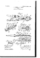
- Figure 1 is a view of an alligator-wrench having our invention fitted to the handle thereof.
- Fig. 2 is a detailed view showing a portion of the cap-plate cut away and part of the device in section.
- Fig. 3 is an enlarged detail in perspective of the device with the cap-plate removed.
- Fig. 4 is a longitudinal section on the line 4 4 of Fig. 1.
- Fig. 5 is a detail of the cap-plate and attached parts.
- Fig. 6 is a longitudinal sectional detail with the cap-plate removed.
- Fig. 7 is a sectional detail on the line 7 7 of Fig. 2, and Fig. 8 is a side elevation of one of our interchangeable dies.
- a cap piece or plate C Fitted over the handle a is a cap piece or plate C, which is provided with an overhanging portion 0, which hooks over the end of the handle a.
- the overhanging portion a not only overhangs the rounded end of the handle a, but incloses it laterally, so that lateral movement of the handle and of the plate with relation to each other is prevented. Obviously this same result can be attained by any suitable coengaging conformation of these parts.
- the plate 0 is further held in position by a thumb-screw D, which passes therethrough and is screwed into a threaded recess formed in the handle a to receive it.
- This plate O is provided with a raised portion, within which is formed an openinglfi of smaller diameter than the extreme diameter of the upper surface of the die A, so that the raised portion of the plate O overhangs the flange B of the die A. Consequently the die A is firmly but rotatively clamped between the plate O and the handle a.
- the raised portion of the plate C also provides a housing F, within which are mounted a bolt Gand a spring II.
- the flange B is provided with a plu' spring H. Normally, however, the spring H presses the bolt G against the periphery of the flange B upon the die A, so that whenever one of the notches b in the flange B registers with the bolt G the bolt G is seated within such notch and the die A is securely held against rotation.
- the bolt G may be mounted upon a guiding-pin, as shown.
- the thumb-screw D is unscrewed from the handle a, whereupon the cap-plate C is lifted off, the die A is removed, and a die of the required size and pitch is substituted therefor, the cap-plate C is replaced, the thumb-nut D is screwed up, and the tool is ready to resume operations;
- An attachment for a toolhandle provided with an opening therethrough, comprising a plate so formed as to hook over said handle, and to be also secured thereto by separate attaching means, combined with a spring-pressed bolt carried by said'plate and adapted to have locking engagement with a die when mounted in said opening.
Landscapes
- Engineering & Computer Science (AREA)
- Mechanical Engineering (AREA)
- Table Equipment (AREA)
Description
. i a v M 0 JV A w t w W m m A \v f P v .V
H. A. SMITH & W. F. FRENK.
TOOL
APPLICATION FILED SEPT. 22, 1904.
SMITH.
To all whont if Duty concern:
Be it known that we, HENRY ADALBERT SMITH, residing at Elgin, and I/VILLIAM FRED F RENK, residing at Dundee, in the county of Kane and State of Illinois, citizens of the United States, have invented certain new and useful Improvements in Tools, of which the following is a specification.
Our invention relates to improvements in bolt threading devices, and is especially adapted and intended for use in connection with wrenches, especially alligator-wrenches, and so is shown as applied to the handle of an alligator-wrench of the type patented to Henry Adalbert Smith in Patent N 0. 584,019. WVrenches of this sort are commonly used as a pocket-tool for linemen and mechanics in tightening and loosening nuts of various sizes, especially in altering and repairing machinery. It frequently happens that in driving the bolt into place the thread thereon is so marred as to make it impossible to apply the nut when the bolt is replaced, thus necessitating the removal of the bolt and rethreading it in the machine-shop or replacing it with a new bolt. Obviously this proceeding is many times inconvenient, and obviously with ordinary means for bolt threading it is found impossible to rethread a bolt in a given position on the machine.
The object of our invention is to provide a tool of compact and convenient structure which may be readily fitted with interchangeable dies to fit any desired size of bolt and pitch of thread, which may be operated to thread or rethread a bolt in any desired position, and which is particularly adapted for application to the handle of other tools, such as the handle of a wrench. These and such other objects as may hereinafter appear are attained by our invention, a convenient em bodiment of which is shown in the accompanying drawings, in which.
Figure 1 is a view of an alligator-wrench having our invention fitted to the handle thereof. Fig. 2 is a detailed view showing a portion of the cap-plate cut away and part of the device in section. Fig. 3 is an enlarged detail in perspective of the device with the cap-plate removed. Fig. 4 is a longitudinal section on the line 4 4 of Fig. 1. Fig. 5 is a detail of the cap-plate and attached parts. Fig. 6 is a longitudinal sectional detail with the cap-plate removed.
Specification of Letters Patent.
Application filed September 22,1904. Serial No. 225,530.
UNITED STATES PATENT OFFICE.
HENRY ADALBERT SMITH, OF ELGIN, AND WVILLIAH FRED FRENK, OF DUNDEE, ILLINOIS; SAID FRENK ASSIGNOR OF ONETENTH TO SAID TOOL.
Patented Jan. 9, 1906.
Fig. 7 is a sectional detail on the line 7 7 of Fig. 2, and Fig. 8 is a side elevation of one of our interchangeable dies.
Like letters of reference indicate the same parts in the several figures of the drawings.
Referring by letter to the accompanying drawings, as commonly constructed wrenches of the type shown are put upon the market with an opening in the handle thereof for convenience in carrying the same or in hangingit in position to lessen weight, &c. Taking, for example, a wrench having such a handle, we mount therein a circular die A, such as is shown in Fig. 8, said die being provided with a laterallyextending flange B, the parts being so proportioned that the body of the die will rotatively fit within said opening, while the flange B will rest upon the face of the handle surrounding said openmg. rality of notches 1), preferably four notches, as shown in the drawings. Fitted over the handle a is a cap piece or plate C, which is provided with an overhanging portion 0, which hooks over the end of the handle a. It will be noted that in the particular embodiment of our invention shown in the drawings the overhanging portion a not only overhangs the rounded end of the handle a, but incloses it laterally, so that lateral movement of the handle and of the plate with relation to each other is prevented. Obviously this same result can be attained by any suitable coengaging conformation of these parts. The plate 0 is further held in position by a thumb-screw D, which passes therethrough and is screwed into a threaded recess formed in the handle a to receive it. This plate O is provided with a raised portion, within which is formed an openinglfi of smaller diameter than the extreme diameter of the upper surface of the die A, so that the raised portion of the plate O overhangs the flange B of the die A. Consequently the die A is firmly but rotatively clamped between the plate O and the handle a. The raised portion of the plate C also provides a housing F, within which are mounted a bolt Gand a spring II.
I is a thumb-piece which is secured to the bolt G by means of a stem, which extends through a slot in the housing F, so that by means of the thumb-piece I the bolt G may be reciprocated against the force of the The flange B is provided with a plu' spring H. Normally, however, the spring H presses the bolt G against the periphery of the flange B upon the die A, so that whenever one of the notches b in the flange B registers with the bolt G the bolt G is seated within such notch and the die A is securely held against rotation.
Whenever the bolt G is forced back against the spring H, it will be carried back sufliciently far to clear the flange B, so that the die may rotate with relation to the handle a, and vice versa.
As a matter of convenience the bolt G may be mounted upon a guiding-pin, as shown.
It will thus be seen that in the operation of our'device with the boltG seated in one of the notches b we have a fixed thread-cutting die which may be constructed as a tool by itself or which may be readily attached to the handle of other tools, while for operation in corners and like positions we have a ratchetdie operating as follows: The die being located in position, the tool is carried part way around, the die cutting a corresponding distance upon the thread of the bolt, whereupon with his thumb the operator retracts the bolt G at the same instant that he moves the handle in the reverse direction. This will unlock the die from the handle, so that while the die is held in position upon the bolt by frictional contact therewith the handle a will be rotated in reverse position upon the die until the bolt G comes opposite the next notch b, whereupon the bolt G will snap into position upon said notch, and the handle being again drawn forward the die is given a further turn upon the bolt, and so on until the thread-cutting is completed. If, however, a diflerent size of die is required, the thumb-screw D is unscrewed from the handle a, whereupon the cap-plate C is lifted off, the die A is removed, and a die of the required size and pitch is substituted therefor, the cap-plate C is replaced, the thumb-nut D is screwed up, and the tool is ready to resume operations;
While we have shown and described our 1 invention as applied to the use of a threadingdie, it will be evident that it is equally adapted to use for other-shaped dies-as, for example, with dies having a polygonal or other shaped opening to fit a bolt made so as to serve as a wrenchand of course dies fo other purposes which may suggest themselves may also be used without departing from the spirit of our invention.
Obviously many variations in detail may be made without departing from the spirit of our invention.
We claim 1. The combination with a stock, of a die rotatably mounted therein, a plate formed to hook over one end of said stock, means for additionally securing said plate to said stock, a spring-pressed dog mounted in a pocket formed in said plate and arranged to lock said die against rotation, and means for moving said dog out of locking position.
2. The combination of a support, a flanged die rotatably mounted therein, an embossed plate removably secured to said support so as to clamp said die in place, a springpressed bolt mounted in said embossed plate and arranged to engage the periphery of said die at a plurality of points successively, so as to lock said die against rotation, and adapted to be disengaged from said die,
I so as to permit the rotation of said die with reference to said support and said plate.
3. An attachment for a toolhandle, provided with an opening therethrough, comprising a plate so formed as to hook over said handle, and to be also secured thereto by separate attaching means, combined with a spring-pressed bolt carried by said'plate and adapted to have locking engagement with a die when mounted in said opening.
HENRY ADALBERT SMITH. WILLIAM FRED FRENK.
Witnesses:
W. A. SCHROEDER, J. F. FIERKE.
Priority Applications (1)
| Application Number | Priority Date | Filing Date | Title |
|---|---|---|---|
| US22553004A US809755A (en) | 1904-09-22 | 1904-09-22 | Tool. |
Applications Claiming Priority (1)
| Application Number | Priority Date | Filing Date | Title |
|---|---|---|---|
| US22553004A US809755A (en) | 1904-09-22 | 1904-09-22 | Tool. |
Publications (1)
| Publication Number | Publication Date |
|---|---|
| US809755A true US809755A (en) | 1906-01-09 |
Family
ID=2878236
Family Applications (1)
| Application Number | Title | Priority Date | Filing Date |
|---|---|---|---|
| US22553004A Expired - Lifetime US809755A (en) | 1904-09-22 | 1904-09-22 | Tool. |
Country Status (1)
| Country | Link |
|---|---|
| US (1) | US809755A (en) |
-
1904
- 1904-09-22 US US22553004A patent/US809755A/en not_active Expired - Lifetime
Similar Documents
| Publication | Publication Date | Title |
|---|---|---|
| US20100326246A1 (en) | Wrench with switchable ratchet wheel sets | |
| US3587271A (en) | Manually operable tool for installing blind anchor nuts | |
| US5526723A (en) | Striking tool | |
| US3508455A (en) | Combination tool | |
| US3361170A (en) | Hand tool with torque augmenting means | |
| US3289503A (en) | Allen wrench device | |
| US809755A (en) | Tool. | |
| US2667801A (en) | Wrench construction | |
| US779632A (en) | Nut-lock. | |
| US864007A (en) | Wrench. | |
| US4005622A (en) | Circular saw wrench | |
| US1119900A (en) | Ratchet-wrench. | |
| US338282A (en) | Screw-threading device | |
| US950675A (en) | Ratchet-wrench. | |
| US2526617A (en) | Multiple toolholder | |
| US613759A (en) | Combination-tool | |
| US1239620A (en) | Vise. | |
| US878197A (en) | Wrench. | |
| US599194A (en) | Morrill hart poor | |
| US20220143722A1 (en) | Threader and rethreading tool | |
| US526658A (en) | Horace polis | |
| US610455A (en) | James mcsweeny | |
| US995003A (en) | Holdback and face-plate dog for lathes. | |
| US794310A (en) | Combination-tool. | |
| KR200280972Y1 (en) | A Pipe Wrench |