US80966A - jones - Google Patents
jones Download PDFInfo
- Publication number
- US80966A US80966A US80966DA US80966A US 80966 A US80966 A US 80966A US 80966D A US80966D A US 80966DA US 80966 A US80966 A US 80966A
- Authority
- US
- United States
- Prior art keywords
- vessel
- hoop
- attached
- wire cloth
- flange
- Prior art date
- Legal status (The legal status is an assumption and is not a legal conclusion. Google has not performed a legal analysis and makes no representation as to the accuracy of the status listed.)
- Expired - Lifetime
Links
- 239000004744 fabric Substances 0.000 description 8
- 239000000463 material Substances 0.000 description 5
- 238000010276 construction Methods 0.000 description 2
- 235000015110 jellies Nutrition 0.000 description 2
- 235000000832 Ayote Nutrition 0.000 description 1
- 241000219122 Cucurbita Species 0.000 description 1
- 235000009854 Cucurbita moschata Nutrition 0.000 description 1
- 235000009804 Cucurbita pepo subsp pepo Nutrition 0.000 description 1
- 244000141359 Malus pumila Species 0.000 description 1
- 235000021016 apples Nutrition 0.000 description 1
- 230000015572 biosynthetic process Effects 0.000 description 1
- 235000015136 pumpkin Nutrition 0.000 description 1
- 230000000284 resting effect Effects 0.000 description 1
- 238000007665 sagging Methods 0.000 description 1
- 238000012216 screening Methods 0.000 description 1
- 239000000126 substance Substances 0.000 description 1
- 235000019640 taste Nutrition 0.000 description 1
Images

Classifications
-
- B—PERFORMING OPERATIONS; TRANSPORTING
- B07—SEPARATING SOLIDS FROM SOLIDS; SORTING
- B07B—SEPARATING SOLIDS FROM SOLIDS BY SIEVING, SCREENING, SIFTING OR BY USING GAS CURRENTS; SEPARATING BY OTHER DRY METHODS APPLICABLE TO BULK MATERIAL, e.g. LOOSE ARTICLES FIT TO BE HANDLED LIKE BULK MATERIAL
- B07B1/00—Sieving, screening, sifting, or sorting solid materials using networks, gratings, grids, or the like
- B07B1/46—Constructional details of screens in general; Cleaning or heating of screens
Definitions
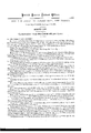
- Figure 2 is a vertical cross-section of the-same, taken through the line a: :v, fig. 1.
- My invention has for its object to furnish an improved sieve, designed to take the place ofthe cullenders, sieves, and coarse cloths that are now used for screening and straining pumpkins, apples, &c., and materials for catsup's, jellies, lite, which shall be simple in construction and efl'ective and convenient in use.
- A is a pan or dish, made with vertical sides, or with the upper parts of its sides vertical, and which may be of any desired or convenient size.
- the pan A should he provided with handles a, and with a spout, ar for convenience in pouring out the strained material, and with-ears, a for securing it to a table or other support when desired.
- B is a band or hoop,- fitting loosely into the mouth of the pan or dish A, and to the lupper edge of which is attached an annular plate, C, of such a size as to project both upon the outer and inner sides ofsaid hoop B, as shown in fig. 2, the outer part or flange of said plate resting upon the upper edge of the pan or dish A..
- D is-a cylindrical vessel, of such a size as to fit intothc interior of the annular plate C, and which has an outwardly-projecting flange formed upon its lower end,'undcrlapping .the inwardly-projecting part or; flange of the annular or ring-plate C.
- the flange of the vessel D is turned back upon itself to form a groove to receive the edge of the wire cloth E.
- this groove may be formed by attaching aring-plate to the under sideof the flange of the said vessel D.
- i i 1 i F is a hoop, fitting into the intcriorof the hoop B, upon the upper edge of which rests the flange of the vessel D, and which is detachably secured to the said hoop B by pins, screws, bolts, or other convenient detachable moans.
- the bars G are bars passing across and attached to the hoop F, beloiv the wire cloth E.-
- the bars G serve a double purpose: thcysupport the middle part of the wire cloth when in use, and prevent its sagging and bagging, and-also seni e .to clean oil the lower side of the said wire cloth, so that it may not be necessary to remove the vessel D for that purpose.
- H is a handle attached to the vessel-D, for convenience in operating it, and ivhich'is removably attached to said vessel, so that it may be easily detached when it is desired to remove the said vessel D from its place.
- I is a presser, which is attached to and suspended from the bar J, the ends of which are attached to the upper ends of the short po-st K, thc'lower ends o'f which aresecured to the annular plate C, upon opposite sides of the vessel D, as shown in figs. 1 and 2.
- the presser I is,,made ofsuch a depth that its lower edge, which is rounded off as shown in fig. 2 may be a little above the wire cloth E, as shownin fig. 2., I i
- This device is designed for bringing the material into proper position and pressing it down upon the wire cloth, so that it may be no longer necessary to wait for the material to be screened or strained to become so cold that the hands of the operator can be put into it, as is now necessary, thus enabling the substance to be strained or screened while very hot, which is a great advantage.
- the machine In the case of factories where jellies, jams, catsups, 860., are prepared and put up for market, the machine may be made large, and maybe driven by power applied by any of the well-known means for such purposes.
Landscapes
- Food-Manufacturing Devices (AREA)
Description
gotten tastes against. @ffisz.
Letters Patent No: 80,966, dated August 11, 1868.
IMPROVED SIEVE.
dig; gtlgthlllt nfzrnt it in time getter ntnit amt uniting n at flge same.
TO ALL WHOM IT MAY CONCERN:
Be it known that I, Mrs. J. D. JONES, of Jersey City, in the county of Hudson, and State of New Jersey,
have invented a new and useful Improvement in Sieves; and I do hereby declare that the following is a full, clear, and exact description thereof, which will enable others skilled in the art to make and use the same,
reference being bad to the accompanying drawings forming part of this specification, in which- Figure 1 is a top or plan view of my improved sieve.
Figure 2is a vertical cross-section of the-same, taken through the line a: :v, fig. 1.
Similar letters of reference indicate like parts. l
My invention has for its object to furnish an improved sieve, designed to take the place ofthe cullenders, sieves, and coarse cloths that are now used for screening and straining pumpkins, apples, &c., and materials for catsup's, jellies, lite, which shall be simple in construction and efl'ective and convenient in use.
It consists in the construction and combination of the various parts, as hereinafter more fully described.
A is a pan or dish, made with vertical sides, or with the upper parts of its sides vertical, and which may be of any desired or convenient size.
The pan A should he provided with handles a, and with a spout, ar for convenience in pouring out the strained material, and with-ears, a for securing it to a table or other support when desired.
B isa band or hoop,- fitting loosely into the mouth of the pan or dish A, and to the lupper edge of which is attached an annular plate, C, of such a size as to project both upon the outer and inner sides ofsaid hoop B, as shown in fig. 2, the outer part or flange of said plate resting upon the upper edge of the pan or dish A..
D is-a cylindrical vessel, of such a size as to fit intothc interior of the annular plate C, and which has an outwardly-projecting flange formed upon its lower end,'undcrlapping .the inwardly-projecting part or; flange of the annular or ring-plate C. I i
The flange of the vessel D is turned back upon itself to form a groove to receive the edge of the wire cloth E.
If desired, this groove may be formed by attaching aring-plate to the under sideof the flange of the said vessel D. i i 1 i F is a hoop, fitting into the intcriorof the hoop B, upon the upper edge of which rests the flange of the vessel D, and which is detachably secured to the said hoop B by pins, screws, bolts, or other convenient detachable moans. I
G are bars passing across and attached to the hoop F, beloiv the wire cloth E.- The bars G serve a double purpose: thcysupport the middle part of the wire cloth when in use, and prevent its sagging and bagging, and-also seni e .to clean oil the lower side of the said wire cloth, so that it may not be necessary to remove the vessel D for that purpose. I
H is a handle attached to the vessel-D, for convenience in operating it, and ivhich'is removably attached to said vessel, so that it may be easily detached when it is desired to remove the said vessel D from its place.
I is a presser, which is attached to and suspended from the bar J, the ends of which are attached to the upper ends of the short po-st K, thc'lower ends o'f which aresecured to the annular plate C, upon opposite sides of the vessel D, as shown in figs. 1 and 2.
The presser I is,,made ofsuch a depth that its lower edge, which is rounded off as shown in fig. 2 may be a little above the wire cloth E, as shownin fig. 2., I i
, To the opposite sides of the presser I, are attached the inner ends of the arms L, which have cross-heads M attached to their outer ends, said cross-heads M being made convex upon their outer sides to correspond with the curve of the vessel D, and concave upon their inner'sidcs, as shown in .fig. 1, so that as the vessel D is moved back and forth, the cross-head scrapers M may prevent the formation of. currents, at the same time moving the material slightly inward, and stopping it in such a. position that the presser I may act upon itto force it into closer contact with the wire cloth E, and thus hasten the operation. 7 i
This device is designed for bringing the material into proper position and pressing it down upon the wire cloth, so that it may be no longer necessary to wait for the material to be screened or strained to become so cold that the hands of the operator can be put into it, as is now necessary, thus enabling the substance to be strained or screened while very hot, which is a great advantage.
In the case of factories where jellies, jams, catsups, 860., are prepared and put up for market, the machine may be made large, and maybe driven by power applied by any of the well-known means for such purposes.
Having thus described my invention, I claim as new, and desire to secure by Letters Patent- 1. The dish or pan-A, or equivalent vessel, hoop B, annular.'plate C, flanged cylindrical vessel D, wire cloth E, and detachable hoop F, having.cross-bars G, attached to it, in combination with each other, said parts being constructed and arranged substantially as herein shown and described, and for the purpose set forth.
2. The presser and scrapers I J K L M, constructed substantially as herein shown and described, in
combination with the devices A B C DE FG, as and for the purposes set forth.
' MRS. J. D. JONES.
Witness es J AS. VAN BENSOHOTEN, IssAc WAKEFIELD.
Publications (1)
| Publication Number | Publication Date |
|---|---|
| US80966A true US80966A (en) | 1868-08-11 |
Family
ID=2150460
Family Applications (1)
| Application Number | Title | Priority Date | Filing Date |
|---|---|---|---|
| US80966D Expired - Lifetime US80966A (en) | jones |
Country Status (1)
| Country | Link |
|---|---|
| US (1) | US80966A (en) |
-
0
- US US80966D patent/US80966A/en not_active Expired - Lifetime
Similar Documents
| Publication | Publication Date | Title |
|---|---|---|
| US80966A (en) | jones | |
| US1517624A (en) | Combination fruit crusher and flour sifter | |
| US80035A (en) | trtjxell | |
| US581628A (en) | Vegetable sieve and strainer | |
| US63090A (en) | Improved pbess strainer | |
| US494753A (en) | Combined flour and meal sifter | |
| US55807A (en) | Improved grater and egg-beater | |
| US101423A (en) | Improved flour-sifter, colander, and strainer | |
| US54994A (en) | Improved flour-sieve | |
| US1267417A (en) | Strainer attachment for drinking vessels. | |
| US85551A (en) | Improvement in butter-worker | |
| US4364A (en) | Improvement in the double seamer for working sheet metal | |
| US719337A (en) | Combined flour tank and sifter. | |
| US75043A (en) | Duncan morrison | |
| US61494A (en) | George c | |
| US78981A (en) | Improved combined peess and strainer | |
| US56964A (en) | massee | |
| USRE3702E (en) | Joseph h | |
| US337711A (en) | Flour scoop and sifter | |
| US85827A (en) | holmes | |
| US70377A (en) | Improved flouk-sifteb | |
| US1041331A (en) | Strainer for milk-cans. | |
| US70367A (en) | Daniel scanlin | |
| US87904A (en) | Improvement in milk-strainer | |
| US1042272A (en) | Pail. |