US809665A - Holder for match-boxes. - Google Patents
Holder for match-boxes. Download PDFInfo
- Publication number
- US809665A US809665A US27670505A US1905276705A US809665A US 809665 A US809665 A US 809665A US 27670505 A US27670505 A US 27670505A US 1905276705 A US1905276705 A US 1905276705A US 809665 A US809665 A US 809665A
- Authority
- US
- United States
- Prior art keywords
- holder
- box
- match
- boxes
- tongue
- Prior art date
- Legal status (The legal status is an assumption and is not a legal conclusion. Google has not performed a legal analysis and makes no representation as to the accuracy of the status listed.)
- Expired - Lifetime
Links
- 210000002105 tongue Anatomy 0.000 description 10
- 238000010276 construction Methods 0.000 description 2
- 230000006378 damage Effects 0.000 description 1
- 238000000605 extraction Methods 0.000 description 1
- 239000002184 metal Substances 0.000 description 1
- 238000000034 method Methods 0.000 description 1
- 238000012986 modification Methods 0.000 description 1
- 230000004048 modification Effects 0.000 description 1
Images
Classifications
-
- A—HUMAN NECESSITIES
- A24—TOBACCO; CIGARS; CIGARETTES; SIMULATED SMOKING DEVICES; SMOKERS' REQUISITES
- A24F—SMOKERS' REQUISITES; MATCH BOXES; SIMULATED SMOKING DEVICES
- A24F19/00—Ash-trays
- A24F19/10—Ash-trays combined with other articles
- A24F19/12—Ash-trays combined with other articles with match-boxes
Definitions
- the object of this invention is to provide a holder for retaining and protecting an ordinary match-box in such a manner that the said box when once placed thereon cannot be removed without the destruction thereof, a further object being to provide a holder of this class which will permit of the outward movement of the drawer or receiver a suflieient distance to permit of the extraction of a match therefrom, and a still further object being to provide a holder for match-boxes which will not permit the removal of the said drawer or receiver from the said box, but which limits the movement thereof and which is simple in construction and operation, very inexpensive, and well adapted for the purpose for which it is intended.
- a holder a comprising an upper member I) and a lower member 0.
- the upper member 1) consists of a plate preferably provided at its upper end with an opening 6 by means of which it may be suspended from a hook or nail; but in practice I prefer to secure a chain in the opening b and secure the other end of the chain to a wall or other suitable plate.
- the plate I) is provided at a point adjacent to the bottom thereof with an outwardly and upwardly bent tongue b ,formed integrally therewith, and at a point adjacent to the top thereof are two forwardly-directed lugs b, and beneath the lugs b are two rearwardly and downwardly directed tongue members 11
- the member 0 also consists of a plate bent at the bottom thereof, as shown at 0 to form a forwardly and upwardly directed spring tongue or member c, which is provided centrally with an opening a, and the part c is also provided at the bottom thereof with forwardly-directed lugs 0 and, as clearly shown in Fig.
- the member 0 is shorter than the member I), and when in position for use the spring-tongue b enters the opening a" and holds the member I) against upward movement and the part 0 against downward movement, and the top of the member 0 is held beneath the spring tongue 5 thereby preventing outward movement thereof.
- Fig. 2 of the drawings 1 have shown a box of matches comprising a casing d and a receiver (1 within which are placed the matches (1, and the method of securing the box of matches on my holder is as follows, reference being had to Fig. 3 of the drawings:
- the member 0 is taken in one hand and the box of matches in a closed position inthe other hand, with the openside of the receiver (Z away from the member 0, and the upwardly-directed part c of the member 0 is in serted between the box (Z and the back of the receiver at and forced upwardly until the box (1 rests on the lug-s0
- the bottom of the men ber Z) is then inserted between the casing d and the back of the receiver (1 and forced downwardly, the lower end thereof passing between the casing d and the upwardlydirected member 0 and when forced down a sufficient distance an audible click is heard when the tongue b enters the opening 0 which looks the two members I) and c together, as previously described, and the box (Z cannot
- My invention is preferably composed of thin spring metal and may be made in various sizes in order to adapt the same to the various sizes of match-boxes, and when a box is emptied and it is desired to replace the same the casing d must be destroyed before the members I) and 0 can be separated, and while I have shown the spring-tongue b as an automatic locking device in connection with the opening 0 it will be apparent that other devices for this purpose may be employed, and various other changes in and modifications of the construction herein shown and described may be made without departing from the spirit of my invention or sacrificing its advantages.
- a matchbox holder comprising top and bottom parts, the top part comprising a plate provided near its upper end with forwardly-directed lugs and at a predetermined distance below said lugs with backwardly and downwardly directed tongues, said plate being also provided near its lower end with a forwardly and upwardly directed tongue; and the bottom part being also composed of a plate the lower end of which is bent forwardly and upwardly to form a springtongue having-a transverse opening, and said bottom part being also provided at its lower end with forwardly-directed lugs, substantially as shown and described.
- a match-box holder composed of top and bottom parts, the top part being composed of a plate provided at its upper end with forwardly-directed lugs and beneath said lugs with backwardly and downwardly directed tongues; and the bottom part being also composed of a plate having forwardlydirected lugs at its lower end and provided with a forwardly and upwardly directed spring-tongue, and means for locking the lower end of the top part and said spring tongue together, substantially as shown and described.
Landscapes
- Purses, Travelling Bags, Baskets, Or Suitcases (AREA)
Description
PATENTED' JAN. 9, 1906.
J. BERRYMAN.
HOLDER FOR MATCH BOXES.
APPLICATION FILED SEPT. 1, 1905.
WITNESSES A Tron/van;
UNITE SATES JOHN BERRYMAN, OF CLIFTON, BRISTOL,
ENGLAND.
HOLDER FOR MATCH-BOXES.
Specification of Letters Patent.
Patented Jam 9, 1906.
Application filed September 1, 1905. Serial No. 276,705.
10 (0M wlwm, it may concern;
Beit known that I, J onNlBnRnYMAN, a subject of the King of Great Britain, residing at Clifton, Bristol, England, have invented certain new and useful Improvements in Holders for Match-Boxes, of which the following is a specification, such as will enable those skilled in the art to which it appertains to make and use the same.
The object of this invention is to provide a holder for retaining and protecting an ordinary match-box in such a manner that the said box when once placed thereon cannot be removed without the destruction thereof, a further object being to provide a holder of this class which will permit of the outward movement of the drawer or receiver a suflieient distance to permit of the extraction of a match therefrom, and a still further object being to provide a holder for match-boxes which will not permit the removal of the said drawer or receiver from the said box, but which limits the movement thereof and which is simple in construction and operation, very inexpensive, and well adapted for the purpose for which it is intended.
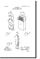
The invention is fully disclosed in the fol lowing specification, of which the accompanying drawings form a part, in which the separate parts of my improvement are designated by suitable reference characters in each of the views, and in which Figure 1 is a perspective front view of my holder in an engaged or locked position; Fig. 2, a similar view thereof with a box of matches in a locked position thereon, and Fig. 3 a section on the line 3 3 of Fig. 1 and the box in a position for use.
In the drawings forming part of this specification I have shown a holder a, comprising an upper member I) and a lower member 0. The upper member 1) consists of a plate preferably provided at its upper end with an opening 6 by means of which it may be suspended from a hook or nail; but in practice I prefer to secure a chain in the opening b and secure the other end of the chain to a wall or other suitable plate. The plate I) is provided at a point adjacent to the bottom thereof with an outwardly and upwardly bent tongue b ,formed integrally therewith, and at a point adjacent to the top thereof are two forwardly-directed lugs b, and beneath the lugs b are two rearwardly and downwardly directed tongue members 11 The member 0 also consists of a plate bent at the bottom thereof, as shown at 0 to form a forwardly and upwardly directed spring tongue or member c, which is provided centrally with an opening a, and the part c is also provided at the bottom thereof with forwardly-directed lugs 0 and, as clearly shown in Fig. 1, the member 0 is shorter than the member I), and when in position for use the spring-tongue b enters the opening a" and holds the member I) against upward movement and the part 0 against downward movement, and the top of the member 0 is held beneath the spring tongue 5 thereby preventing outward movement thereof.
In Fig. 2 of the drawings 1 have shown a box of matches comprising a casing d and a receiver (1 within which are placed the matches (1, and the method of securing the box of matches on my holder is as follows, reference being had to Fig. 3 of the drawings: The member 0 is taken in one hand and the box of matches in a closed position inthe other hand, with the openside of the receiver (Z away from the member 0, and the upwardly-directed part c of the member 0 is in serted between the box (Z and the back of the receiver at and forced upwardly until the box (1 rests on the lug-s0 The bottom of the men ber Z) is then inserted between the casing d and the back of the receiver (1 and forced downwardly, the lower end thereof passing between the casing d and the upwardlydirected member 0 and when forced down a sufficient distance an audible click is heard when the tongue b enters the opening 0 which looks the two members I) and c together, as previously described, and the box (Z cannot be removed therefrom without de stroying the same, and at this time the spring tongues b engage the top of the member a and if the box (Z is of a proper size also engage it, and not only is the box held thereby against movement, but the member 0 is also held against such movement, and when the box (1 is so locked in position the receiver (1 thereof may be forced upwardly until it reaches the lugs b", which prevent the further movement thereof, and thebox of matches is then in the position shown in Fig. 2, at which time one or more matches may be extracted therefrom, but the box cannot be taken from the holder.
My invention is preferably composed of thin spring metal and may be made in various sizes in order to adapt the same to the various sizes of match-boxes, and when a box is emptied and it is desired to replace the same the casing d must be destroyed before the members I) and 0 can be separated, and while I have shown the spring-tongue b as an automatic locking device in connection with the opening 0 it will be apparent that other devices for this purpose may be employed, and various other changes in and modifications of the construction herein shown and described may be made without departing from the spirit of my invention or sacrificing its advantages.
Having fully described my invention, What I claim as new, and desire to secure by Letters Patent, is
1. A matchbox holder, comprising top and bottom parts, the top part comprising a plate provided near its upper end with forwardly-directed lugs and at a predetermined distance below said lugs with backwardly and downwardly directed tongues, said plate being also provided near its lower end with a forwardly and upwardly directed tongue; and the bottom part being also composed of a plate the lower end of which is bent forwardly and upwardly to form a springtongue having-a transverse opening, and said bottom part being also provided at its lower end with forwardly-directed lugs, substantially as shown and described.
2. A match-box holder, composed of top and bottom parts, the top part being composed of a plate provided at its upper end with forwardly-directed lugs and beneath said lugs with backwardly and downwardly directed tongues; and the bottom part being also composed of a plate having forwardlydirected lugs at its lower end and provided with a forwardly and upwardly directed spring-tongue, and means for locking the lower end of the top part and said spring tongue together, substantially as shown and described.
In testimony that I claim the foregoing as my invention 1 have signed my name, in presence of the subscribing witnesses, this 19th day of August, 1905.
JOHN BERRYMAN.
Witnesses: V
LORIN A. LATHROP, 1 E. M. TOLERTON.
Priority Applications (1)
| Application Number | Priority Date | Filing Date | Title |
|---|---|---|---|
| US27670505A US809665A (en) | 1905-09-01 | 1905-09-01 | Holder for match-boxes. |
Applications Claiming Priority (1)
| Application Number | Priority Date | Filing Date | Title |
|---|---|---|---|
| US27670505A US809665A (en) | 1905-09-01 | 1905-09-01 | Holder for match-boxes. |
Publications (1)
| Publication Number | Publication Date |
|---|---|
| US809665A true US809665A (en) | 1906-01-09 |
Family
ID=2878146
Family Applications (1)
| Application Number | Title | Priority Date | Filing Date |
|---|---|---|---|
| US27670505A Expired - Lifetime US809665A (en) | 1905-09-01 | 1905-09-01 | Holder for match-boxes. |
Country Status (1)
| Country | Link |
|---|---|
| US (1) | US809665A (en) |
-
1905
- 1905-09-01 US US27670505A patent/US809665A/en not_active Expired - Lifetime
Similar Documents
| Publication | Publication Date | Title |
|---|---|---|
| US472238A (en) | John m | |
| US809665A (en) | Holder for match-boxes. | |
| US925524A (en) | Letter-box. | |
| US1959963A (en) | Mail box | |
| US865475A (en) | Smoker's net. | |
| US958648A (en) | Coin-holder or change-maker. | |
| US1001080A (en) | Mail-box. | |
| US379680A (en) | op new yoek | |
| US409055A (en) | Match-safe | |
| US824995A (en) | Receptacle for matches. | |
| US825987A (en) | Match-box. | |
| US1057480A (en) | Match-box holder. | |
| US575489A (en) | Zachariah douglas morrow | |
| US818246A (en) | Match-box. | |
| US582775A (en) | Match-safe | |
| US888462A (en) | Match-receptacle. | |
| US705578A (en) | Match-box. | |
| US866526A (en) | Flue-stopper. | |
| US819964A (en) | Match-box. | |
| US751043A (en) | Akthuk b | |
| US481696A (en) | Automatic match-safe | |
| US758467A (en) | Match-box holder. | |
| US905081A (en) | Holder for match-boxes. | |
| US902682A (en) | Match-safe. | |
| US1115175A (en) | Match-box. |