US809647A - Electric cell. - Google Patents
Electric cell. Download PDFInfo
- Publication number
- US809647A US809647A US18906604A US1904189066A US809647A US 809647 A US809647 A US 809647A US 18906604 A US18906604 A US 18906604A US 1904189066 A US1904189066 A US 1904189066A US 809647 A US809647 A US 809647A
- Authority
- US
- United States
- Prior art keywords
- cell
- carbon tube
- grams
- electric cell
- mixture
- Prior art date
- Legal status (The legal status is an assumption and is not a legal conclusion. Google has not performed a legal analysis and makes no representation as to the accuracy of the status listed.)
- Expired - Lifetime
Links
- OKTJSMMVPCPJKN-UHFFFAOYSA-N Carbon Chemical compound [C] OKTJSMMVPCPJKN-UHFFFAOYSA-N 0.000 description 11
- 229910052799 carbon Inorganic materials 0.000 description 10
- 239000000463 material Substances 0.000 description 6
- 239000000203 mixture Substances 0.000 description 6
- XLYOFNOQVPJJNP-UHFFFAOYSA-N water Substances O XLYOFNOQVPJJNP-UHFFFAOYSA-N 0.000 description 5
- 239000012286 potassium permanganate Substances 0.000 description 3
- NLXLAEXVIDQMFP-UHFFFAOYSA-N Ammonia chloride Chemical compound [NH4+].[Cl-] NLXLAEXVIDQMFP-UHFFFAOYSA-N 0.000 description 2
- WCUXLLCKKVVCTQ-UHFFFAOYSA-M Potassium chloride Chemical compound [Cl-].[K+] WCUXLLCKKVVCTQ-UHFFFAOYSA-M 0.000 description 2
- -1 one hundred grams Chemical compound 0.000 description 2
- 230000010287 polarization Effects 0.000 description 2
- 239000012047 saturated solution Substances 0.000 description 2
- DOBUSJIVSSJEDA-UHFFFAOYSA-L 1,3-dioxa-2$l^{6}-thia-4-mercuracyclobutane 2,2-dioxide Chemical compound [Hg+2].[O-]S([O-])(=O)=O DOBUSJIVSSJEDA-UHFFFAOYSA-L 0.000 description 1
- 241000345998 Calamus manan Species 0.000 description 1
- HCHKCACWOHOZIP-UHFFFAOYSA-N Zinc Chemical compound [Zn] HCHKCACWOHOZIP-UHFFFAOYSA-N 0.000 description 1
- GOPYZMJAIPBUGX-UHFFFAOYSA-N [O-2].[O-2].[Mn+4] Chemical compound [O-2].[O-2].[Mn+4] GOPYZMJAIPBUGX-UHFFFAOYSA-N 0.000 description 1
- 239000010426 asphalt Substances 0.000 description 1
- 238000010276 construction Methods 0.000 description 1
- 230000002999 depolarising effect Effects 0.000 description 1
- 239000011521 glass Substances 0.000 description 1
- 239000010439 graphite Substances 0.000 description 1
- 229910002804 graphite Inorganic materials 0.000 description 1
- 239000010440 gypsum Substances 0.000 description 1
- 229910052602 gypsum Inorganic materials 0.000 description 1
- 229940074994 mercuric sulfate Drugs 0.000 description 1
- 229910000372 mercury(II) sulfate Inorganic materials 0.000 description 1
- 238000000034 method Methods 0.000 description 1
- 229940037201 oris Drugs 0.000 description 1
- 235000012950 rattan cane Nutrition 0.000 description 1
- 239000003566 sealing material Substances 0.000 description 1
- 239000000126 substance Substances 0.000 description 1
- 239000011701 zinc Substances 0.000 description 1
- 229910052725 zinc Inorganic materials 0.000 description 1
Images
Classifications
-
- H—ELECTRICITY
- H01—ELECTRIC ELEMENTS
- H01M—PROCESSES OR MEANS, e.g. BATTERIES, FOR THE DIRECT CONVERSION OF CHEMICAL ENERGY INTO ELECTRICAL ENERGY
- H01M6/00—Primary cells; Manufacture thereof
- H01M6/30—Deferred-action cells
- H01M6/32—Deferred-action cells activated through external addition of electrolyte or of electrolyte components
Definitions
- the present invention has relation to electric cells, and has for its objects the following: first, to reduce internal resistance and also action of polarization to increase electromotive power; second, to prolong the life of the cell.
- 1 represents the shell or casing, which is formed of a size to correspond substantially with the size of the cell designed to be constructed.
- the carbon tube 2 which carbon tube has located around it oris covered with blotting-paper or like material, which is held in place by the binding-cords 3, which binding-cords maybe located as illustrated in the drawings, or they may be differently located, as the only object is to hold the blotting-paper or like material in proper relative position.
- the carbon tube, together with the different parts connected thereto, are placed in the shell or casing in a concentric manner, as illustrated in the drawings.
- the carbon tube proper Within the carbon tube proper is located the following mixture, which mixture is treated as follows: Graphite, two hundred and forty grams; manganese dioxid, one hundred and sixty grams; potassium chlorid, eight grams; potassium permanganate, twenty grams, and ammonium chlorid, fifty grams, are boiled with five hundred grams of saturated solution of potassium permanganate, pressed to a definite form in a mold, and the mixture is strongly attached to the carbon tube in a crystalline form by the crystallizing action of potassium permanganate from its saturated solution.
- the blotting paper 4 covers the above-mentioned mixture.
- a depolarizing mixture Within the carbon tube 2 is located a depolarizing mixture, and between the cylindrical zinc case or shell 1 and the blottingpaper 4 is located the followin mixture: ammonium chlorid, one hundred grams, potassium chlorid, eight grams, gypsum, four hundred grams, mercuric sulfate, one gram, and gextgin, five hundred grams, well mixed and
- the carbon tube 2 is provided with an aperture 5, in which aperture is located a stopper 6, made of material having many capillaries in its structure.
- the stopper may be made of rattan or like material and is formed of material such as above described for the purpose of letting gas out and at the same time preventing the rapid flow of water.
- a stratum of sawdust 7 orlike material from which leads the tube 8, which tube is preferably formed of glass and is for the purpose of permitting.
- the top of the casing l is hermetically sealed by asphalt or other suitable substance; but the top of the sealing material 9 should be a short distance below the top of the case 1, so that water may be placed in the cell proper, as hereinafter described.
- the terminals of the cell, 10 and 11, are of the usual construction and constitute the negative and positive poles, the terminal 1() being attached to the carbon tube 2 and the terminal 11 to the casing 1.
- the cell In use the cell remains dry after being completed until it is desired to produce a current, and when used for the first time the stopper- 6 should be removed and the upper part of the cell filled with clean water, the water being poured in as it becomes absorbed. This process should be repeated twice or three times, after which the stopper 6 is placed in its normal condition.
- the cell may be safely used directly after the water is poured in; but three or four hours later the electric motive power will become 1.6 volts and, the internal resistance and the polarization being very slow, it possesses very much practical advantage in every way.
- the shape of the cell' may be varied, if so desired, without altering in the least the present invention.
Landscapes
- Engineering & Computer Science (AREA)
- Manufacturing & Machinery (AREA)
- Chemical & Material Sciences (AREA)
- Chemical Kinetics & Catalysis (AREA)
- Electrochemistry (AREA)
- General Chemical & Material Sciences (AREA)
- Primary Cells (AREA)
Description
PATENTED JAN. 9, 1906.
K TSUKAMOTO ELECTRIC CELL.
APPLICATION FILED JAN.14, 1904.
l Il
a. do I: 1: i=5; E W
INVENTOR s CL s 8 CL N W W ATTORNEY unrrnn STAT ES;
PATENT OFFICE.
Specification of Letters Patent.
Patented Jan. 9, 1906.
Application filed January 14, 1904. Serial No. 189,066.
To ti/Z zu/mm/ 111; nuty concern:
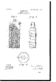
Be it known that I, KUMAJIRO TSUKAMOTO, a citizen of the Empire of Japan, residing at Tokyo,Tokyo Fu, Province of Musashi, Japan, have invented certain new and useful Improvements in Electric Cells; and I do hereby declare that the following is a full, clear, and exact description of the same, reference being had to the annexed drawings, making a part of this specification, and to the figures of reference marked thereon, in which Figure 1 is a vertical section showing the different parts properly arranged. Fig. 2 is a view of the carbon tube. Fig. 3 is a top view.
The present invention has relation to electric cells, and has for its objects the following: first, to reduce internal resistance and also action of polarization to increase electromotive power; second, to prolong the life of the cell.
Similar numerals of reference indicate corresponding parts in all the figures of the drawings.
In the accompanying drawings, 1 represents the shell or casing, which is formed of a size to correspond substantially with the size of the cell designed to be constructed. Within the shell is located the carbon tube 2, which carbon tube has located around it oris covered with blotting-paper or like material, which is held in place by the binding-cords 3, which binding-cords maybe located as illustrated in the drawings, or they may be differently located, as the only object is to hold the blotting-paper or like material in proper relative position. The carbon tube, together with the different parts connected thereto, are placed in the shell or casing in a concentric manner, as illustrated in the drawings. Within the carbon tube proper is located the following mixture, which mixture is treated as follows: Graphite, two hundred and forty grams; manganese dioxid, one hundred and sixty grams; potassium chlorid, eight grams; potassium permanganate, twenty grams, and ammonium chlorid, fifty grams, are boiled with five hundred grams of saturated solution of potassium permanganate, pressed to a definite form in a mold, and the mixture is strongly attached to the carbon tube in a crystalline form by the crystallizing action of potassium permanganate from its saturated solution. The blotting paper 4 covers the above-mentioned mixture.
Within the carbon tube 2 is located a depolarizing mixture, and between the cylindrical zinc case or shell 1 and the blottingpaper 4 is located the followin mixture: ammonium chlorid, one hundred grams, potassium chlorid, eight grams, gypsum, four hundred grams, mercuric sulfate, one gram, and gextgin, five hundred grams, well mixed and The carbon tube 2 is provided with an aperture 5, in which aperture is located a stopper 6, made of material having many capillaries in its structure. The stopper may be made of rattan or like material and is formed of material such as above described for the purpose of letting gas out and at the same time preventing the rapid flow of water.
At the top or upper end of the case 1 and below the covering thereof is located a stratum of sawdust 7 orlike material, from which leads the tube 8, which tube is preferably formed of glass and is for the purpose of permitting.
the gas to escape.
The top of the casing l is hermetically sealed by asphalt or other suitable substance; but the top of the sealing material 9 should be a short distance below the top of the case 1, so that water may be placed in the cell proper, as hereinafter described.
The terminals of the cell, 10 and 11, are of the usual construction and constitute the negative and positive poles, the terminal 1() being attached to the carbon tube 2 and the terminal 11 to the casing 1.
In use the cell remains dry after being completed until it is desired to produce a current, and when used for the first time the stopper- 6 should be removed and the upper part of the cell filled with clean water, the water being poured in as it becomes absorbed. This process should be repeated twice or three times, after which the stopper 6 is placed in its normal condition.
It will be understood that the cell may be safely used directly after the water is poured in; but three or four hours later the electric motive power will become 1.6 volts and, the internal resistance and the polarization being very slow, it possesses very much practical advantage in every way.
The shape of the cell'may be varied, if so desired, without altering in the least the present invention.
Having fully described my invention, what I claim as new, and desire to secure by Letters Patent, is
10 the shell and the fibrous or blotting paper located around the carbon tube, substantially as and for the purpose specified.
In testimony that I claim the above I have hereunto subscribed my name in the presence of two wltnesses.
KUMAJIRO TSUKAMOTO.
Witnesses:
R. S. MILLER, YETARo KINOSITA.
Priority Applications (1)
| Application Number | Priority Date | Filing Date | Title |
|---|---|---|---|
| US18906604A US809647A (en) | 1904-01-14 | 1904-01-14 | Electric cell. |
Applications Claiming Priority (1)
| Application Number | Priority Date | Filing Date | Title |
|---|---|---|---|
| US18906604A US809647A (en) | 1904-01-14 | 1904-01-14 | Electric cell. |
Publications (1)
| Publication Number | Publication Date |
|---|---|
| US809647A true US809647A (en) | 1906-01-09 |
Family
ID=2878128
Family Applications (1)
| Application Number | Title | Priority Date | Filing Date |
|---|---|---|---|
| US18906604A Expired - Lifetime US809647A (en) | 1904-01-14 | 1904-01-14 | Electric cell. |
Country Status (1)
| Country | Link |
|---|---|
| US (1) | US809647A (en) |
Cited By (1)
| Publication number | Priority date | Publication date | Assignee | Title |
|---|---|---|---|---|
| US3018314A (en) * | 1954-03-16 | 1962-01-23 | Yardney International Corp | Filling mechanism for deferred-action batteries |
-
1904
- 1904-01-14 US US18906604A patent/US809647A/en not_active Expired - Lifetime
Cited By (1)
| Publication number | Priority date | Publication date | Assignee | Title |
|---|---|---|---|---|
| US3018314A (en) * | 1954-03-16 | 1962-01-23 | Yardney International Corp | Filling mechanism for deferred-action batteries |
Similar Documents
| Publication | Publication Date | Title |
|---|---|---|
| SU676189A3 (en) | Device for using solar energy | |
| SE7611485L (en) | ELECTRIC CELL | |
| GB1376807A (en) | Cylindrical electrochemical cell | |
| US3615831A (en) | Lead oxide-sulfuric acid battery having a positive electrode comprising a titaniummolybdenum-zirconium alloy grid | |
| SE7504149L (en) | WAY TO POWER ELECTROLYTICAL MEMBRANE CELLS WITH HORIZONTAL ELECTRODES. | |
| US809647A (en) | Electric cell. | |
| JPS5931573A (en) | Negative electrode for lithium battery | |
| US2928889A (en) | Sealed electrolytic cell with auxiliary electrode | |
| US3836403A (en) | Lithium batteries and method of preparing a positive electrode material therefor | |
| US1766418A (en) | Electric cell | |
| US1406429A (en) | Dry cell | |
| US1279280A (en) | Secondary battery-cell. | |
| US3416963A (en) | Electrochemical cell | |
| SU121159A1 (en) | Solid Electrolyte Fuel Cell | |
| US1436873A (en) | Reversible battery | |
| SU458907A1 (en) | Sealed alkaline nickel-cadmium battery | |
| US851402A (en) | Dry battery. | |
| JPS5543719A (en) | Dry cell | |
| SU117837A1 (en) | Galvanic battery flap type air depolarization | |
| US1161398A (en) | Storage battery. | |
| AT72397B (en) | Dry element. | |
| JPS5818746B2 (en) | Sodium - Sulfur Denthi | |
| JPS5725678A (en) | Sealed storage battery | |
| JPS57128468A (en) | Fuel cell composed of sheet-like ion exchanger electrolyte membrane | |
| GB163318A (en) | Dry cell and method of manufacturing the same |