US809494A - Binder. - Google Patents
Binder. Download PDFInfo
- Publication number
- US809494A US809494A US26865905A US1905268659A US809494A US 809494 A US809494 A US 809494A US 26865905 A US26865905 A US 26865905A US 1905268659 A US1905268659 A US 1905268659A US 809494 A US809494 A US 809494A
- Authority
- US
- United States
- Prior art keywords
- post
- pawl
- casing
- dog
- clamping members
- Prior art date
- Legal status (The legal status is an assumption and is not a legal conclusion. Google has not performed a legal analysis and makes no representation as to the accuracy of the status listed.)
- Expired - Lifetime
Links
- 239000011230 binding agent Substances 0.000 title description 23
- 230000003534 oscillatory effect Effects 0.000 description 14
- 238000010276 construction Methods 0.000 description 8
- 230000004048 modification Effects 0.000 description 3
- 238000012986 modification Methods 0.000 description 3
- 238000009877 rendering Methods 0.000 description 3
- NDNUANOUGZGEPO-QMMMGPOBSA-N (+)-coniine Chemical compound CCC[C@H]1CCCCN1 NDNUANOUGZGEPO-QMMMGPOBSA-N 0.000 description 1
- 229940077451 coniine Drugs 0.000 description 1
- 229930016881 coniine Natural products 0.000 description 1
- NDNUANOUGZGEPO-UHFFFAOYSA-N rac-coniine Natural products CCCC1CCCCN1 NDNUANOUGZGEPO-UHFFFAOYSA-N 0.000 description 1
- 238000000926 separation method Methods 0.000 description 1
Images
Classifications
-
- B—PERFORMING OPERATIONS; TRANSPORTING
- B42—BOOKBINDING; ALBUMS; FILES; SPECIAL PRINTED MATTER
- B42F—SHEETS TEMPORARILY ATTACHED TOGETHER; FILING APPLIANCES; FILE CARDS; INDEXING
- B42F13/00—Filing appliances with means for engaging perforations or slots
Definitions
- This invention relates to adevice which may be applied to binders of the looseleaf type, the object being to provide a device of simple construction which may be used in connection with covers or binders of this class which may be easily operated and which will be positive in its action.
- binders of this description is well vunderstood and it is not thought necessary to enter into an explanation of their operation further than to state the principal requirement,
- the object of my invention is to provide a device which shall meet this requirement and accomplish the desired result by the use of a simple locking mechanism which does not require separate keys or other devices to operate the same and which shall be self-contained and operated by turning the book on one side to lock the covers in any desired position and to release the same by simply reversing the position of the book.
- I provide an upper and lower clamping-section, which may be attached to the covers of the binder. These clamping-sections are normally held apart by the action of springs contained in telescoping members attached to said clamping-sections in the usual manner.
- AttachedV to one of these clamping-sections, preferably the upper, I provide a post which carries a rotary pawl or dog, which is adapted to engage projections on the interior of a cooperating post or casing, which is secured to the lower clamping-section.
- This latter post or casing is adapted to telescope over the post carrying the pawl or dog,
- the construction of these parts is such that when the clamping-sections and attached covers are in the position shown in the drawings a free inward movement is permitted and the leaves may be clamped and held between the clamping-sections by pressing the upper cover down.
- the pawl or dog will engage the projections upon the outer post or casing and so hold the Specification of Letters Patent. Application filed July 7,1905. Serial No. 268,659.
- auxiliary weight cooperates With the rotary pawl or dog to hold the same in its operative position when the parts are in the position just described.
- this auxiliary weight drops out of engagement with the pawl and allows the same to rotate out lof engagement with the casing, and so permits the clamping members to be separated.
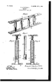
- Figure 1 is a perspective side elevation of a pair of clamping-sections or binder-frames with the covers and leaves of the book omitted.
- Fig. 2 is an enlarged side elevation in section of a post and casing carrying a locking mechanism.
- Fig. 3 is an enlarged side elevation and detail view of the post carrying the pawl or dog.
- Fig. 4 is an enlarged side .elevation in section of a post and casing, showing a modification of the rotary pawl forming a part of the locking mechanism.
- Fig. 1 at l and 2 is shown an upper and lower clamping-section, respectively, which may be attached by any suitable means to the cover of the binder, or, if preferred, the covers themselves may form the clampingsections and have the locking device attached directly thereto.
- telescoping members containing springs which operate normally to separate the c amping members 1 and 2 when not held in position by means of the locking mechanism carried by the post 4 and casing 7.
- this locking mechanism is on the principle of a pawl-and-ratchet device, the distinguishing features of this device being in the construction and mode of operation of the rotary pawl and an auxiliary locking-weight, which operates in conjunction therewith to hold this pawl in such positions that the outer end thereof will engage projections on the interior of the casing 7 when the covers are in one position, and when the covers are reversed in position this auxiliary weight drops out of engagement with the pawl,-rendering the same inoperative.
- a post which is secured to the upper clamping member 1 by any suitable means and preferably in such a manner that the same may be rotated. This may be done by socketing the post 4 in the clamping IOO member 1 and holding the same in such a position by means of an ordinary flat-headed screw, as shown in the drawings.
- This screw may be secured in the post 4 by any suitable means, and by using an ordinary screw-driver in the slot thereof the post may be rotated as desired.
- a recess or slot in which is carried a pawl 5.
- This pawl is pivotally supported in said slot at 6.
- a chamber 9 is also provided at the lower end of the post 4 in proximity to the recess carrying the pawl 5.
- auxiliary weight 8 which when the members are in the position-shown in the drawings will drop to the lower end of the chamber 9, in which position it engages the pawl 5 and prevents the same from rotating in one direction, and so locks or holds said pawl in a position such that the outer end thereof engages the projections on the interior of the casing 7.
- the casing 7 is secured to the lower clamping member 2 by any suitable means and is adapted to telescope over the post 4.
- the inner surface of this casing is provided with serrations or projections, which are preferably in the form of a screw-thread or spiral.
- the object of providing projections of this kind is to allow of a further tightening of the clamping members by rotating the post 4 and the attached pawl, as already described.
- the recess or slot in which the pawl is located has the upper portion thereof so formed as to provide a stop to limit the movement of the pawl in this direction, and consequently it is prevented from falling into suchposition that the reversal of the covers to the position shown would fail to bring the several parts into operative position already described.
- Fig. 4 is shown a modification of the pawl and locking mechanism.
- the operation of the parts in this construction is the same as the one already described, and the same description may be applied thereto, using the reference-number 5 for the pawl, 6 Afor the pivot, 8 for the auxiliary weight, and 9 for the chamber for said weight.
- the outer end of the pawl in this construction is provided with a plurality of projections corresponding to the threaded interior surface of the casing 7. The outer ends of these projections or teeth may be arranged on the arc of the circle to permit the rotation of the pawl 5 around its pivot 6.
- the device herein shown and described as an illustration of an operative embodiment of my invention is composed of a very small number of parts and that such parts are of a simple construction and may be easily and cheaply manufactured. It will be also noted that the device when assembled is very compact in form and that the operating parts are self-contained within the same.
- What I claim is- 1.
- a binder the combination of a pair of clamping members, a post attached to one of said members, an oscillatory pawl or dog carried by said post and adapted to engage the inner surface o f a casing, a casing secured to the other of ksaid clamping members and adapted to telescope over said post, an auxiliary weight cooperating with said pawl or dog to lock the same in engagement with said casing, substantially as described.
- a binder the combination of a pair of clamping members, a post having a slot at the lower end thereof attached to one of said clamping members, an oscillatory pawl or dog carried by said post in said slot and adapted to engage the inner surface of a casing, a casing secured to the other of said clamping members and adapted to telescope over said post, an auxiliary weight cooperating with said pawl or' dog to lock the same in engagement with said casing, substantially as described.
- a binder In a binder, the combination of a pair of clamping members, a post having a slot at the lower end thereof attached to one .of said clamping members, an oscillatory pawl or dog carried by said post in said slot in such a manner that the movement thereof is limited by an auxiliary weight in one direction so that the outer end of said pawl Will engage the inner surface of a casing, a casing secured to the other of said clamping members and adapted to telescope over said post, an auxiliary weight cooperating with said pawl or dog to hold the same in engagement with said casing, substantially as described.
- a binder the combination of a pair of clamping members, a post attached to one of said clamping members, an oscillatory pawl or dog carried by said post and adapted to engage the inner surface of a casing, a casing having a serrated inner surface secured to the other of said clamping members and adapted to telescope over said post, an auxiliary IOO IIO
- a binder the combination of a pair of clamping members, a post attached to one of said clamping members, an oscillatory pawl or dog carried by said post and adapted to engage the inner surface of a casing, a casing having a threaded inner surface secured to the other of said clamping members and adapted to telescope over said post, means for rotating said post in said casing, an auxiliary weight cooperating with said pawl or dog to hold the same in engagement with said casing, substantially as described.
- a binder the combination of a pair of clamping members, a post having a recess at the lower end thereof attached to one of said clamping members an oscillatory pawl or dog carried by said post in said recess and adapted to engage the inner surface of a casing, a casing secured to the other of said clamping members and adapted to telescope over said post, an auxiliary weight located in a chamber in said post cooperating with said pawl or dog to lock the same in engagement with said casing, substantially as described.
- a binder the combination of a pair of clamping members, a post having a slot at the lower end thereof, an oscillatory pawly or dog pivotally attached to said post in said slot and having a portion thereof adapted to engage the inner surface of a casing, a casing secured to the other of said clamping members and adapted to telescope over said post, an auxiliary weight cooperating with said pawl or dog to lock the same in engagement with saidvcasing, substantially as described.
- a binder the combination of a pair of clamping members, a post having a slot at the lower end thereof, an oscillatory pawl or dog pivotally attached to said post in said slot having a portion thereof adapted to engage the inner surface of a casing and having a portion thereof adapted to engage an auxiliary weight to hold the same in position, a casing secured to the other of said clamping members and adapted to telescope over said post, .an auxiliary weight cooperating with said pawl or dog to lock the same in engagement with said casing, substantially as described.
- a binder the combination of a pair of clamping members, a post attached to one of said clamping members, an oscillatory pawl or dog pivotally attached to said post, having a portion thereof adapted to engage the inner surface of a casing and a portion thereof flattened to engage an auxiliary lockingweight, a casing secured to the other of said clamping members and adapted to telescope over said post, an auxiliary Weight coperating with said pawl or dog to lock and hold the same in engagement with said casing, sub- Stantially as described.
- a binder the combination of a pair of clamping members, a post attached to one of said clamping members, an oscillatory ⁇ pawl or dog pivotally attached to said post, having a portion thereof adapted to engage the inner surface of a casing and a portion thereof adapted to be engaged by an auxiliary weight, a casing secured to the other of said clamping members and adapted to telescope over said post, an auxiliary weight cooperating with said pawl or dog to hold the same in engagement with said casing and adapted to drop out of engagement with the pawl when the clamping members are reversed in position thus rendering the pawl inoperative and allowing the clamping members to be separated, substantially as described.
- a locking device the combination of a pair of telescoping members, an oscillatory pawl or dog carried by the inner of said members, an auxiliary weight carried by said innermember and so located in relation to said pawl as to lock the same in an operative position and adapted to drop out of engagement with said pawl when the members are reversed in position thus rendering the pawl inoperative and allowing the telescoping members to be separated, substantially as described.
- a binder the combination of a pair of clamping members, a post having a slot at the lower end thereof, an oscillatory pawl or dog pivotally attached to said post in said slot, said slot having a portion thereof forming a stop to limit the'movement of said pawl in one directioman auxiliary weight located in a chamber adjacent to said slot in said post and adapted to limit the movement of said pawl in the opposite direction when the members are in one position and adapted to fall out of engagement with said pawl when the position of the members is reversed, a casing secured to the other of said clamping members and adapted to telescope over said post, substantially as described.
- a binder the combination of a pair of clamping members, a post attached to one of said members, an oscillatory pawl or dog carried by said post and adapted to engage the inner surface of a casing, a casing secured to the other of said clamping members and adapted to telescope over said post, and an auxiliary member adapted to engage and lock said pawl or dog and adapted to fall out of engagement with the same when the binder is reversed.
- a binder the combination of a pair of clamping members, a post attached to one of said members, an oscillatory pawl or dog carried by said post and adapted to engage the inner surface of a casing, a casing secured to the other o ⁇ f said clamping members, and adapted to telescope over said post, and an auxiliary member carried in a recess in said IOO TIO
Landscapes
- Clamps And Clips (AREA)
Description
PATENTED JAN. 9, 1906.
' F. A. CLEVELAND.
BINDER. APPLICATION FILED JULY 7, 1905.
W/ TNE SSE S: /l/
invirnn STATESv PATENT onricn.
FREDERICK A. CLEVELAND, OF NEW YORK, N. Y.
BINDER.
To a/ZZ whom t may concern:
Be it known that I, FREDERICK A. CLEVE- LAND, a citizen of the United States, and a resident of New York, in the county of New York and State of New York, have invented certain new and useful Improvements in Binders, of which the following is a specification.
This invention relates to adevice which may be applied to binders of the looseleaf type, the object being to provide a device of simple construction which may be used in connection with covers or binders of this class which may be easily operated and which will be positive in its action. The use of binders of this description is well vunderstood and it is not thought necessary to enter into an explanation of their operation further than to state the principal requirement,
which is that any number of pages or leaves may be inserted, replaced, or taken out without disturbing the remaining leaves.
The object of my invention is to provide a device which shall meet this requirement and accomplish the desired result by the use of a simple locking mechanism which does not require separate keys or other devices to operate the same and which shall be self-contained and operated by turning the book on one side to lock the covers in any desired position and to release the same by simply reversing the position of the book. To accomplish this result, I provide an upper and lower clamping-section, which may be attached to the covers of the binder. These clamping-sections are normally held apart by the action of springs contained in telescoping members attached to said clamping-sections in the usual manner. AttachedV to one of these clamping-sections, preferably the upper, I provide a post which carries a rotary pawl or dog, which is adapted to engage projections on the interior of a cooperating post or casing, which is secured to the lower clamping-section. This latter post or casing is adapted to telescope over the post carrying the pawl or dog, The construction of these parts is such that when the clamping-sections and attached covers are in the position shown in the drawings a free inward movement is permitted and the leaves may be clamped and held between the clamping-sections by pressing the upper cover down. The pawl or dog will engage the projections upon the outer post or casing and so hold the Specification of Letters Patent. Application filed July 7,1905. Serial No. 268,659.
Patented J' an. 9, 1906.
parts in position. An auxiliary weight cooperates With the rotary pawl or dog to hold the same in its operative position when the parts are in the position just described. When the position of the covers is reversed, this auxiliary weight drops out of engagement with the pawl and allows the same to rotate out lof engagement with the casing, and so permits the clamping members to be separated.
The construction and operation of the device will be more fully explained in connection with the drawings accompanying this specification.
Figure 1 is a perspective side elevation of a pair of clamping-sections or binder-frames with the covers and leaves of the book omitted. Fig. 2 is an enlarged side elevation in section of a post and casing carrying a locking mechanism. Fig. 3 is an enlarged side elevation and detail view of the post carrying the pawl or dog. Fig. 4 is an enlarged side .elevation in section of a post and casing, showing a modification of the rotary pawl forming a part of the locking mechanism.
In Fig. 1, at l and 2, is shown an upper and lower clamping-section, respectively, which may be attached by any suitable means to the cover of the binder, or, if preferred, the covers themselves may form the clampingsections and have the locking device attached directly thereto. At 3 3 are shown telescoping members containing springs which operate normally to separate the c amping members 1 and 2 when not held in position by means of the locking mechanism carried by the post 4 and casing 7. The operation of this locking mechanism is on the principle of a pawl-and-ratchet device, the distinguishing features of this device being in the construction and mode of operation of the rotary pawl and an auxiliary locking-weight, which operates in conjunction therewith to hold this pawl in such positions that the outer end thereof will engage projections on the interior of the casing 7 when the covers are in one position, and when the covers are reversed in position this auxiliary weight drops out of engagement with the pawl,-rendering the same inoperative.
At 4 is shown a post, which is secured to the upper clamping member 1 by any suitable means and preferably in such a manner that the same may be rotated. This may be done by socketing the post 4 in the clamping IOO member 1 and holding the same in such a position by means of an ordinary flat-headed screw, as shown in the drawings. This screw may be secured in the post 4 by any suitable means, and by using an ordinary screw-driver in the slot thereof the post may be rotated as desired. At the lower end of this post 4 is provided a recess or slot in which is carried a pawl 5. This pawl is pivotally supported in said slot at 6. A chamber 9 is also provided at the lower end of the post 4 in proximity to the recess carrying the pawl 5. In this chamber isl carried an auxiliary weight 8, which when the members are in the position-shown in the drawings will drop to the lower end of the chamber 9, in which position it engages the pawl 5 and prevents the same from rotating in one direction, and so locks or holds said pawl in a position such that the outer end thereof engages the projections on the interior of the casing 7.
The casing 7 is secured to the lower clamping member 2 by any suitable means and is adapted to telescope over the post 4. The inner surface of this casing is provided with serrations or projections, which are preferably in the form of a screw-thread or spiral. The object of providing projections of this kind is to allow of a further tightening of the clamping members by rotating the post 4 and the attached pawl, as already described.
When the parts are in the position shown,
- the separation of the clamping members is prevented, as the outer end of the pawl engages the projections already described, and as the pawl is prevented from rotating in the direction corresponding to an outward movement of the post and casing by means of the auxiliary Weight 8 thel members are held in this position. When the position of the covers is reversed, the auxiliary weight 8 will drop to the opposite end of its chamber 9. The pawl 5 is now free to rotate on its pivot 6, and consequently the post and casing, with the attached clamping members, maybe separated. The recess or slot in which the pawl is located has the upper portion thereof so formed as to provide a stop to limit the movement of the pawl in this direction, and consequently it is prevented from falling into suchposition that the reversal of the covers to the position shown would fail to bring the several parts into operative position already described.
In Fig. 4 is shown a modification of the pawl and locking mechanism. The operation of the parts in this construction is the same as the one already described, and the same description may be applied thereto, using the reference-number 5 for the pawl, 6 Afor the pivot, 8 for the auxiliary weight, and 9 for the chamber for said weight. The outer end of the pawl in this construction is provided with a plurality of projections corresponding to the threaded interior surface of the casing 7. The outer ends of these projections or teeth may be arranged on the arc of the circle to permit the rotation of the pawl 5 around its pivot 6.
It will be noted that the device herein shown and described as an illustration of an operative embodiment of my invention is composed of a very small number of parts and that such parts are of a simple construction and may be easily and cheaply manufactured. It will be also noted that the device when assembled is very compact in form and that the operating parts are self-contained within the same.
I do not coniine myself, however, to the exact details of construction shown and described, as it will be evident that various modifications and changes may be made therein to adapt the device to its several uses without departing from the scope of my invention.
What I claim is- 1. In a binder, the combination of a pair of clamping members, a post attached to one of said members, an oscillatory pawl or dog carried by said post and adapted to engage the inner surface o f a casing, a casing secured to the other of ksaid clamping members and adapted to telescope over said post, an auxiliary weight cooperating with said pawl or dog to lock the same in engagement with said casing, substantially as described.
2. In a binder, the combination of a pair of clamping members, a post having a slot at the lower end thereof attached to one of said clamping members, an oscillatory pawl or dog carried by said post in said slot and adapted to engage the inner surface of a casing, a casing secured to the other of said clamping members and adapted to telescope over said post, an auxiliary weight cooperating with said pawl or' dog to lock the same in engagement with said casing, substantially as described.
3. In a binder, the combination of a pair of clamping members, a post having a slot at the lower end thereof attached to one .of said clamping members, an oscillatory pawl or dog carried by said post in said slot in such a manner that the movement thereof is limited by an auxiliary weight in one direction so that the outer end of said pawl Will engage the inner surface of a casing, a casing secured to the other of said clamping members and adapted to telescope over said post, an auxiliary weight cooperating with said pawl or dog to hold the same in engagement with said casing, substantially as described.
4. In a binder, the combination of a pair of clamping members, a post attached to one of said clamping members, an oscillatory pawl or dog carried by said post and adapted to engage the inner surface of a casing, a casing having a serrated inner surface secured to the other of said clamping members and adapted to telescope over said post, an auxiliary IOO IIO
weight cooperating with said pawl or dog to lock the same in engagement with said cas' ing, substantially as described.
5. In a binder, the combination of a pair of clamping members, a post attached to one of said clamping members, an oscillatory pawl or dog carried by said post and adapted to engage the inner surface of a casing, a casing having a threaded inner surface secured to the other of said clamping members and adapted to telescope over said post, means for rotating said post in said casing, an auxiliary weight cooperating with said pawl or dog to hold the same in engagement with said casing, substantially as described.
6. In a binder, the combination of a pair of clamping members, a post having a recess at the lower end thereof attached to one of said clamping members an oscillatory pawl or dog carried by said post in said recess and adapted to engage the inner surface of a casing, a casing secured to the other of said clamping members and adapted to telescope over said post, an auxiliary weight located in a chamber in said post cooperating with said pawl or dog to lock the same in engagement with said casing, substantially as described.
7. In a binder, the combination of a pair of clamping members, a post having a slot at the lower end thereof, an oscillatory pawly or dog pivotally attached to said post in said slot and having a portion thereof adapted to engage the inner surface of a casing, a casing secured to the other of said clamping members and adapted to telescope over said post, an auxiliary weight cooperating with said pawl or dog to lock the same in engagement with saidvcasing, substantially as described.
8. In a binder, the combination of a pair of clamping members, a post having a slot at the lower end thereof, an oscillatory pawl or dog pivotally attached to said post in said slot having a portion thereof adapted to engage the inner surface of a casing and having a portion thereof adapted to engage an auxiliary weight to hold the same in position, a casing secured to the other of said clamping members and adapted to telescope over said post, .an auxiliary weight cooperating with said pawl or dog to lock the same in engagement with said casing, substantially as described.
9. In a binder, the combination of a pair of clamping members, a post attached to one of said clamping members, an oscillatory pawl or dog pivotally attached to said post, having a portion thereof adapted to engage the inner surface of a casing and a portion thereof flattened to engage an auxiliary lockingweight, a casing secured to the other of said clamping members and adapted to telescope over said post, an auxiliary Weight coperating with said pawl or dog to lock and hold the same in engagement with said casing, sub- Stantially as described.
10. In a binder, the combination of a pair of clamping members, a post attached to one of said clamping members, an oscillatory` pawl or dog pivotally attached to said post, having a portion thereof adapted to engage the inner surface of a casing and a portion thereof adapted to be engaged by an auxiliary weight, a casing secured to the other of said clamping members and adapted to telescope over said post, an auxiliary weight cooperating with said pawl or dog to hold the same in engagement with said casing and adapted to drop out of engagement with the pawl when the clamping members are reversed in position thus rendering the pawl inoperative and allowing the clamping members to be separated, substantially as described.
11. In a locking device, the combination of a pair of telescoping members, an oscillatory pawl or dog carried by the inner of said members, an auxiliary weight carried by said innermember and so located in relation to said pawl as to lock the same in an operative position and adapted to drop out of engagement with said pawl when the members are reversed in position thus rendering the pawl inoperative and allowing the telescoping members to be separated, substantially as described.
12. In a binder, the combination of a pair of clamping members, a post having a slot at the lower end thereof, an oscillatory pawl or dog pivotally attached to said post in said slot, said slot having a portion thereof forming a stop to limit the'movement of said pawl in one directioman auxiliary weight located in a chamber adjacent to said slot in said post and adapted to limit the movement of said pawl in the opposite direction when the members are in one position and adapted to fall out of engagement with said pawl when the position of the members is reversed, a casing secured to the other of said clamping members and adapted to telescope over said post, substantially as described..
13. In a binder, the combination of a pair of clamping members, a post attached to one of said members, an oscillatory pawl or dog carried by said post and adapted to engage the inner surface of a casing, a casing secured to the other of said clamping members and adapted to telescope over said post, and an auxiliary member adapted to engage and lock said pawl or dog and adapted to fall out of engagement with the same when the binder is reversed.
14. In a binder, the combination of a pair of clamping members, a post attached to one of said members, an oscillatory pawl or dog carried by said post and adapted to engage the inner surface of a casing, a casing secured to the other o`f said clamping members, and adapted to telescope over said post, and an auxiliary member carried in a recess in said IOO TIO
post adapted to engage and look said pawl or ed to fall out of engagement when the device 1o dog and adapted to fall out of engagement is reversed. with the same when the binder is reversed. Signed at New York, in the county of New 15. In a binder-lock, in combination, a York and State of New York, this 16th day 5 pair of telesooping members, an oscillatory of June, A. D. 1905.
pawl or dog Carried by one of said members FREDERICK A. CLEVELAND. and adapted to engage the other of said mem- Witnesses: bers, and an auxiliary member adapted to JNO. R. WILDMAN,
engage and lock said pawl or dog and adapt- LEWIS J. DOOLITTLE. i
Priority Applications (1)
| Application Number | Priority Date | Filing Date | Title |
|---|---|---|---|
| US26865905A US809494A (en) | 1905-07-07 | 1905-07-07 | Binder. |
Applications Claiming Priority (1)
| Application Number | Priority Date | Filing Date | Title |
|---|---|---|---|
| US26865905A US809494A (en) | 1905-07-07 | 1905-07-07 | Binder. |
Publications (1)
| Publication Number | Publication Date |
|---|---|
| US809494A true US809494A (en) | 1906-01-09 |
Family
ID=2877975
Family Applications (1)
| Application Number | Title | Priority Date | Filing Date |
|---|---|---|---|
| US26865905A Expired - Lifetime US809494A (en) | 1905-07-07 | 1905-07-07 | Binder. |
Country Status (1)
| Country | Link |
|---|---|
| US (1) | US809494A (en) |
-
1905
- 1905-07-07 US US26865905A patent/US809494A/en not_active Expired - Lifetime
Similar Documents
| Publication | Publication Date | Title |
|---|---|---|
| US1200538A (en) | Hinge. | |
| US809494A (en) | Binder. | |
| US829322A (en) | Binder. | |
| US785834A (en) | Combination-lock. | |
| US809496A (en) | Binder. | |
| US829321A (en) | Loose-leaf binder. | |
| US829324A (en) | Binder. | |
| US809495A (en) | Binder. | |
| US829326A (en) | Binder. | |
| US829325A (en) | Binder. | |
| US809426A (en) | Binder. | |
| US809493A (en) | Binder. | |
| US938621A (en) | Binder. | |
| US579596A (en) | Pencil-case | |
| US1035087A (en) | Loose-leaf binder. | |
| US945916A (en) | Loose-leaf binder. | |
| US1186912A (en) | Book-lock. | |
| US992465A (en) | Loose-leaf binder. | |
| US829323A (en) | Binder. | |
| US1182912A (en) | Combination-padlock. | |
| US1195766A (en) | William t | |
| US468512A (en) | Means for locking books | |
| US964765A (en) | Lock for loose-leaf binders. | |
| US802042A (en) | Loose-leaf binder, file, and the like. | |
| US813919A (en) | Loose-leaf binder. |