US809490A - Safety scaffold-support. - Google Patents
Safety scaffold-support. Download PDFInfo
- Publication number
- US809490A US809490A US28067205A US1905280672A US809490A US 809490 A US809490 A US 809490A US 28067205 A US28067205 A US 28067205A US 1905280672 A US1905280672 A US 1905280672A US 809490 A US809490 A US 809490A
- Authority
- US
- United States
- Prior art keywords
- support
- side members
- ears
- upright
- holes
- Prior art date
- Legal status (The legal status is an assumption and is not a legal conclusion. Google has not performed a legal analysis and makes no representation as to the accuracy of the status listed.)
- Expired - Lifetime
Links
- 210000005069 ears Anatomy 0.000 description 5
- 238000009408 flooring Methods 0.000 description 2
- 230000003313 weakening effect Effects 0.000 description 1
Images
Classifications
-
- A—HUMAN NECESSITIES
- A47—FURNITURE; DOMESTIC ARTICLES OR APPLIANCES; COFFEE MILLS; SPICE MILLS; SUCTION CLEANERS IN GENERAL
- A47B—TABLES; DESKS; OFFICE FURNITURE; CABINETS; DRAWERS; GENERAL DETAILS OF FURNITURE
- A47B57/00—Cabinets, racks or shelf units, characterised by features for adjusting shelves or partitions
- A47B57/30—Cabinets, racks or shelf units, characterised by features for adjusting shelves or partitions with means for adjusting the height of detachable shelf supports
- A47B57/40—Cabinets, racks or shelf units, characterised by features for adjusting shelves or partitions with means for adjusting the height of detachable shelf supports consisting of hooks coacting with openings
- A47B57/42—Cabinets, racks or shelf units, characterised by features for adjusting shelves or partitions with means for adjusting the height of detachable shelf supports consisting of hooks coacting with openings the shelf supports being cantilever brackets
-
- Y—GENERAL TAGGING OF NEW TECHNOLOGICAL DEVELOPMENTS; GENERAL TAGGING OF CROSS-SECTIONAL TECHNOLOGIES SPANNING OVER SEVERAL SECTIONS OF THE IPC; TECHNICAL SUBJECTS COVERED BY FORMER USPC CROSS-REFERENCE ART COLLECTIONS [XRACs] AND DIGESTS
- Y10—TECHNICAL SUBJECTS COVERED BY FORMER USPC
- Y10T—TECHNICAL SUBJECTS COVERED BY FORMER US CLASSIFICATION
- Y10T403/00—Joints and connections
- Y10T403/32—Articulated members
- Y10T403/32254—Lockable at fixed position
- Y10T403/32426—Plural distinct positions
- Y10T403/32442—At least one discrete position
- Y10T403/32451—Step-by-step adjustment
- Y10T403/32459—Retainer extends through aligned recesses
Definitions
- the object of the invention is to produce a safety-support for the floor-beams of a scaffold-staging.
- the drawing shows a perspective view of my device in place on the scaffolding.
- My device which I call a scaffold-flooring support, is indicated in general at a and is made up of a pair of side members 6 b, joined and spaced opposite one another by the brace-bars dd 03
- the lower ends of the side members are bent to U shape, as indicated at e, to receive and retain the floorbeams c for the scaifolding, as hereinafter more fully described.
- the upper ends of the side members are bent rearwardly to form attaching-ears, which are provided with registering holes ff.
- My support is used in the following manner: The scaifold-uprights are pierced at the proper points by transverse holes, and the attaching-ears embrace these uprights g, and a pin it, passing through the holes in the ears and the upright, secures the support in place.
- These scaffolding-uprights are used over and over again, and by having a series of holes F F in the ears my device may be attached wherever there is a convenient hole in an upright. In this way only a small number of holes need be made in the uprights, thus not enormous weakening them.
- the braces d d hold the hanger out from the upright to leave the U-shaped bend unobstructed.
- the flooring-beam for the scaffolding is laid in the U-shaped bend at the lower end of the support and extends to the sides of the building, where it may be fastened, as desired.
- a scaflold-support the side members braced from and secured to one another, rearwardly-extending ears at the upper ends of said side members, by means of which the device may be secured in place, a U-shaped recess formed at the lower end of the device by extending the ends of said members forwardly and then upwardly, and brace-bars providing a stop to hold said U-shaped recess free from the part to which the device is attached.
- a scaffold-flooring support consisting of two side members U-shaped at their lower ends, brace-bars connecting the side members, holes oppositely arranged in the upper ends of the side members, and a securing-pin adapted to pass through said holes and a hole in the upright.
- a scaffold including uprights, floor beams, a platform, of means secured to the uprights for securing the floor-beams, said means comprising side members, brace-bars securing said side members together, attaching-ears formed by extending the upper ends of the side members rearwardly adapted to lie one on each side of the upright, registering holes in said attaching-ears, and the upright, a pin extending through the holes in the ears and upright, the lower ends of the side members being bent forwardly and upwardly forming a recess to receive and retain said flooring-beams.
Landscapes
- Movable Scaffolding (AREA)
Description
No. 809,490. I PATENTED JAN. 9, 1906. P. GAPORALE.
SAFETY SGAPPOLD SUPPORT.
APPLICATION FILED SBPT.29, 1905.
% nesse v iwenfar.
PETER CAPORALE, OF HARTFORD, CONNECTICUT.
SAFETY SGAFFOLD-SUPPORT.
Specification of Letters Patent.
Patented Jan. 9, 1906.
Application filed September 29,1905. Serial No. 280,672.
To all whom it may concern:
Be it known that I, PETER CAPoRALn, a subject of the King of Italy, residing at Hartford, in the county of Hartford and State of Connecticut, have invented certain new and useful Improvements in Safety Scaffold-Supports, of which the following is a specification.
The object of the invention is to produce a safety-support for the floor-beams of a scaffold-staging.
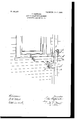
The drawing shows a perspective view of my device in place on the scaffolding.
My device, which I call a scaffold-flooring support, is indicated in general at a and is made up of a pair of side members 6 b, joined and spaced opposite one another by the brace-bars dd 03 The lower ends of the side members are bent to U shape, as indicated at e, to receive and retain the floorbeams c for the scaifolding, as hereinafter more fully described. The upper ends of the side members are bent rearwardly to form attaching-ears, which are provided with registering holes ff.
My support is used in the following manner: The scaifold-uprights are pierced at the proper points by transverse holes, and the attaching-ears embrace these uprights g, and a pin it, passing through the holes in the ears and the upright, secures the support in place. These scaffolding-uprights are used over and over again, and by having a series of holes F F in the ears my device may be attached wherever there is a convenient hole in an upright. In this way only a small number of holes need be made in the uprights, thus not immensely weakening them. The braces d d hold the hanger out from the upright to leave the U-shaped bend unobstructed. The flooring-beam for the scaffolding is laid in the U-shaped bend at the lower end of the support and extends to the sides of the building, where it may be fastened, as desired.
I claim as my invention 1. In a scaflold-support the side members braced from and secured to one another, rearwardly-extending ears at the upper ends of said side members, by means of which the device may be secured in place, a U-shaped recess formed at the lower end of the device by extending the ends of said members forwardly and then upwardly, and brace-bars providing a stop to hold said U-shaped recess free from the part to which the device is attached.
2. In a'scaffold-support the side arms, U- shaped on their lower ends, rearwardly-extending ears lying at each side of the scafloldupright, brace-bars connecting the side members, and means for securing the whole to the upright.
3. A scaffold-flooring support consisting of two side members U-shaped at their lower ends, brace-bars connecting the side members, holes oppositely arranged in the upper ends of the side members, and a securing-pin adapted to pass through said holes and a hole in the upright.
4. The combination with a scaffold including uprights, floor beams, a platform, of means secured to the uprights for securing the floor-beams, said means comprising side members, brace-bars securing said side members together, attaching-ears formed by extending the upper ends of the side members rearwardly adapted to lie one on each side of the upright, registering holes in said attaching-ears, and the upright, a pin extending through the holes in the ears and upright, the lower ends of the side members being bent forwardly and upwardly forming a recess to receive and retain said flooring-beams.
In testimony whereof I aflix my signature in presence of two witnesses.
PETER CAPORALE.
Witnesses:
SALVATOR DEsoPo, J OSEPHIN DEsoro.
Priority Applications (1)
| Application Number | Priority Date | Filing Date | Title |
|---|---|---|---|
| US28067205A US809490A (en) | 1905-09-29 | 1905-09-29 | Safety scaffold-support. |
Applications Claiming Priority (1)
| Application Number | Priority Date | Filing Date | Title |
|---|---|---|---|
| US28067205A US809490A (en) | 1905-09-29 | 1905-09-29 | Safety scaffold-support. |
Publications (1)
| Publication Number | Publication Date |
|---|---|
| US809490A true US809490A (en) | 1906-01-09 |
Family
ID=2877971
Family Applications (1)
| Application Number | Title | Priority Date | Filing Date |
|---|---|---|---|
| US28067205A Expired - Lifetime US809490A (en) | 1905-09-29 | 1905-09-29 | Safety scaffold-support. |
Country Status (1)
| Country | Link |
|---|---|
| US (1) | US809490A (en) |
Cited By (1)
| Publication number | Priority date | Publication date | Assignee | Title |
|---|---|---|---|---|
| US4447049A (en) * | 1982-08-02 | 1984-05-08 | Alumin-Art Plating Company | Apparatus for holding a work piece |
-
1905
- 1905-09-29 US US28067205A patent/US809490A/en not_active Expired - Lifetime
Cited By (1)
| Publication number | Priority date | Publication date | Assignee | Title |
|---|---|---|---|---|
| US4447049A (en) * | 1982-08-02 | 1984-05-08 | Alumin-Art Plating Company | Apparatus for holding a work piece |
Similar Documents
| Publication | Publication Date | Title |
|---|---|---|
| US840365A (en) | Ladder. | |
| US809490A (en) | Safety scaffold-support. | |
| US510194A (en) | Bracket | |
| US763209A (en) | Step-ladder. | |
| US309038A (en) | Ments | |
| US901926A (en) | Safety scaffold-bracket. | |
| US448082A (en) | Clasp for connecting timbers | |
| US802126A (en) | Scaffold-platform. | |
| US390103A (en) | Extension-trestle | |
| US789156A (en) | Folding scaffold or staging-bench. | |
| US1067170A (en) | Orchard step-ladder. | |
| US197766A (en) | Improvement in adjustable ladders | |
| US479662A (en) | Scaffold-bracket | |
| US327427A (en) | zeigler | |
| US267515A (en) | Eobeet m | |
| US904878A (en) | Mine-roof support. | |
| US816458A (en) | Scaffold-support. | |
| US907733A (en) | Swinging chair. | |
| US290487A (en) | Scaffold-support | |
| US178345A (en) | Improvement in step-ladders | |
| US1018658A (en) | Scaffold. | |
| US564048A (en) | crist | |
| US290525A (en) | Harrow | |
| US472160A (en) | Scaffold | |
| US392361A (en) | pierson |