US809481A - Crane mechanism. - Google Patents
Crane mechanism. Download PDFInfo
- Publication number
- US809481A US809481A US26032005A US1905260320A US809481A US 809481 A US809481 A US 809481A US 26032005 A US26032005 A US 26032005A US 1905260320 A US1905260320 A US 1905260320A US 809481 A US809481 A US 809481A
- Authority
- US
- United States
- Prior art keywords
- crane
- jib
- track
- trolley
- traveling crane
- Prior art date
- Legal status (The legal status is an assumption and is not a legal conclusion. Google has not performed a legal analysis and makes no representation as to the accuracy of the status listed.)
- Expired - Lifetime
Links
- 238000010276 construction Methods 0.000 description 4
Images
Classifications
-
- B—PERFORMING OPERATIONS; TRANSPORTING
- B66—HOISTING; LIFTING; HAULING
- B66C—CRANES; LOAD-ENGAGING ELEMENTS OR DEVICES FOR CRANES, CAPSTANS, WINCHES, OR TACKLES
- B66C7/00—Runways, tracks or trackways for trolleys or cranes
Definitions
- This invention relates to improvements in crane mechanism, and has for its object a combination and arrangement of jib-cranes with a traveling crane in such a manner that a trolley-hoist mechanism will operate on both the jib and traveling cranes and pass from one to the other, so that work can be transferred froml one of the jib-cranes to the traveling crane and from the traveling crane to any one of the jib-cranes, as may be desired.
- a further feature of my invention is the providing of mechanism whereby the traveling crane can be locked on its track opposite any one of the jib-cranes and the jib-crane can be locked in line with the traveling crane, so that the trolley-hoist mechanism willtravel from one crane to the other.
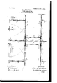
- FIG. l is a top or plan view of a combined traveling-crane and jib-crane mechanism embodying my invention.
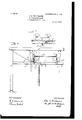
- Fig. 2 is a transverse view in elevation of the same.
- Fig. 3 is a sectional view of the traveling-crane mechanism on the line w in Fig. 2.
- A is the track, and A the track-support, of a traveling crane, .preferably supported by brackets B, secured to overhead beams B, as illustrated ⁇ iny Fig. 2, and preferably extending through a shop.
- a traveling crane the general features of which-viz., the brackets O, forming the ends thereof, the trolleywheels C', and the transverse shafts Cz-are of the usual construction.
- the brackets C are the general features of which-viz., the brackets O, forming the ends thereof, the trolleywheels C', and the transverse shafts Cz-are of the usual construction.
- brackets C there is mounted a latch c, operated by a depending cord c' and Aeling hoist mechanism E.
- the arms F of the jib-cranes F are on the same horizontal plane as the I-beam D of the traveling crane, and
- Fig. l I have shown two machines G and H, adapted to be reached and served by the jib-cranes F on that side of the shop and from which work can be hoisted and carried by one of the jib-cranes F and delivered to the traveling crane, so as to be deposited under the cranewayor carried by the traveling crane to another part of the shop and delivered to another of the jib-cranes on either side of the shop, and vice versa, as may be desired.
- transverse horizontal trolley-track thereon a jib-crane on one side of the line of travel of the traveling crane, a horizontal trolley-track thereon on the same horizontal plane with the trolley-track on the traveling crane, means for locking the jib-crane trolley-track at right angles to the line of travel of the traveling crane, means for locking the traveling crane so that the trolley-track thereon will coincide with the trolley-track on the jib-crane when itis at right angles to the line of travel of the traveling crane.l and a trolley-hoist adapted to operate over both of said trolley-tracks when they coincide as aforesaid and pass from one to the other, substantially as set forth.
Landscapes
- Engineering & Computer Science (AREA)
- Mechanical Engineering (AREA)
- Jib Cranes (AREA)
Description
190,809,481. PATENTBD JAN. 9, 1906. J. P.. WHITTEMORE.
CRANE MEGHANISM. APPLICATION FILED HAY 13, 1905.
2 SHEETS-SHEET 1.
q, ,gxmmw PATENTED JAN. 9, 1906.
J. R. WHITTEMORE. CRANE MECHANISM.
APPLICATION FILED MAY 1a. 1905.
2 SHEETS-SHEET 2.
Mmzssss PATENT OFFICE.
JOHN R. WHITTEMORE, OF ERIE, PENNSYLVANIA.
CRANE NIECHANISM.
Specification of Letters Patent.
Patented Jan. 9, 19C6,
Application filed May 13, 1905. Serial No. 260,320.
T0 .all whom it mtg/ concern: l
Beit known that I, JOHN R. WHITTEMORE. a citizen of the United States, residing at Erie, in the county of` .Erie and State of Pennsylvania, have invented certain new and useful Improvements in CraneMechanism; and I do hereby declare the'following to be a full, clear, and exact description of the invention, such as will enable others skilled in the art to which it appertains to make and use the same, reference being had to the accompanying drawings, and to theletters of reference marked thereon, forming part `.of this speciiication.
This invention relates to improvements in crane mechanism, and has for its object a combination and arrangement of jib-cranes with a traveling crane in such a manner that a trolley-hoist mechanism will operate on both the jib and traveling cranes and pass from one to the other, so that work can be transferred froml one of the jib-cranes to the traveling crane and from the traveling crane to any one of the jib-cranes, as may be desired.
A further feature of my invention is the providing of mechanism whereby the traveling crane can be locked on its track opposite any one of the jib-cranes and the jib-crane can be locked in line with the traveling crane, so that the trolley-hoist mechanism willtravel from one crane to the other.
The features of this invention are herein: after set forth and described, and illustrated in the accompanying drawings, in which- Figure l is a top or plan view of a combined traveling-crane and jib-crane mechanism embodying my invention. Fig. 2 is a transverse view in elevation of the same. Fig. 3 is a sectional view of the traveling-crane mechanism on the line w in Fig. 2.
In the drawings, A is the track, and A the track-support, of a traveling crane, .preferably supported by brackets B, secured to overhead beams B, as illustrated` iny Fig. 2, and preferably extending through a shop. Upon the trackAthere is mounted a traveling crane the general features of which-viz., the brackets O, forming the ends thereof, the trolleywheels C', and the transverse shafts Cz-are of the usual construction. The brackets C,
however, extend down below the track-sup- -ports A and have secured thereto a transverse horizontal I-shaped beam D, which forms a trolley-track D for a trolley-hoist mechanism E.
In one of the brackets C there is mounted a latch c, operated by a depending cord c' and Aeling hoist mechanism E. The arms F of the jib-cranes F are on the same horizontal plane as the I-beam D of the traveling crane, and
when any one of the jib-crane arms F' are moved so as to be at right angles to the tracksupport A' and the traveling crane brought opposite thereto, as shown in Figs. l and 2, the jib-crane arms F and I-beam D on the traveling crane will then coincide and form a continuous track F2 D, as shown in Fig. 2, over which a trolley-hoist E will travel. To retain the arms Fl at right angles to the tracksupport A', as above described, I provide a latchf, mounted on the crane-arm F' and provided with an operating-cord f. This latch f is adapted to engage a stop c on the tracksupport Al when the arm F is at right angles therewith. Y
Referring to Fig. l, I have shown two machines G and H, adapted to be reached and served by the jib-cranes F on that side of the shop and from which work can be hoisted and carried by one of the jib-cranes F and delivered to the traveling crane, so as to be deposited under the cranewayor carried by the traveling crane to another part of the shop and delivered to another of the jib-cranes on either side of the shop, and vice versa, as may be desired.
In the drawings, it will be observed, I have shown the jib-cran'es and the traveling crane as of the ordinary conventional construction, as my invention consists rather in the arrangement of the cranes with relation to each other and the modiiications of construction necessary to adapt them to coperate substantially as described than to the use of any particular type of either jib or traveling crane, as any form of such cranes could readily be arranged and modified in their construction sor as to practically embody m'y invention.
Therefore having thus shown and described convenient mechanism embodying my invention, so as to enable others to utilize the same, what I claim as new, and desire to secure by Letters Patent of the United States, is-
l. The combination of a traveling crane, a
IOO
IIO
i it .4
transverse horizontal trolley-track thereon, a jib-crane on one side of the line of travel of the traveling crane, a horizontal trolley-track thereon on the same horizontal plane with the trolley-track on the traveling crane, means for locking the jib-crane trolley-track at right angles to the line of travel of the traveling crane, means for locking the traveling crane so that the trolley-track thereon will coincide with the trolley-track on the jib-crane when itis at right angles to the line of travel of the traveling crane.l and a trolley-hoist adapted to operate over both of said trolley-tracks when they coincide as aforesaid and pass from one to the other, substantially as set forth.
2. The combination of a traveling crane, tracks therefor supported from above, a transverse horizontal track on said crane below the track-support thereof, a series of jib-cranes on one or both sides of the traveling-crane supports, horizontal trolley-tracks on said jibcranes on the saine horizontal plane with the trolley-track on the traveling crane, means for locking each of said jib-cranes at right angles to the track-support of the traveling crane, latch mechanism for locking the travcling crane in line with each of said jib-cranes when at right angles with the track-support so that the trolley-track on the traveling crane will coincide with the trolley-track on the jib-crane opposite thereto, and a trolley-hoist adapted to travel over the trolley-track on the traveling crane and the trolley-track on the jib-crane coinciding therewith, and from one to the other, substantially as set forth.
In testimony whereofl I affix my signature in presence of two witnesses.`
JOHN R. WHITTEMORE.
Witnesses:
H. M. STURGEON, W. S. CARROLL.
Priority Applications (1)
| Application Number | Priority Date | Filing Date | Title |
|---|---|---|---|
| US26032005A US809481A (en) | 1905-05-13 | 1905-05-13 | Crane mechanism. |
Applications Claiming Priority (1)
| Application Number | Priority Date | Filing Date | Title |
|---|---|---|---|
| US26032005A US809481A (en) | 1905-05-13 | 1905-05-13 | Crane mechanism. |
Publications (1)
| Publication Number | Publication Date |
|---|---|
| US809481A true US809481A (en) | 1906-01-09 |
Family
ID=2877962
Family Applications (1)
| Application Number | Title | Priority Date | Filing Date |
|---|---|---|---|
| US26032005A Expired - Lifetime US809481A (en) | 1905-05-13 | 1905-05-13 | Crane mechanism. |
Country Status (1)
| Country | Link |
|---|---|
| US (1) | US809481A (en) |
Cited By (1)
| Publication number | Priority date | Publication date | Assignee | Title |
|---|---|---|---|---|
| US3191546A (en) * | 1961-03-13 | 1965-06-29 | Pullman Inc | Movable bulkhead |
-
1905
- 1905-05-13 US US26032005A patent/US809481A/en not_active Expired - Lifetime
Cited By (1)
| Publication number | Priority date | Publication date | Assignee | Title |
|---|---|---|---|---|
| US3191546A (en) * | 1961-03-13 | 1965-06-29 | Pullman Inc | Movable bulkhead |
Similar Documents
| Publication | Publication Date | Title |
|---|---|---|
| US809481A (en) | Crane mechanism. | |
| US809482A (en) | Crane-locking mechanism. | |
| US850439A (en) | Overhead traveling crane. | |
| US850407A (en) | Traveling crane. | |
| US878484A (en) | Mechanism for locking trolleys. | |
| US1432378A (en) | Traveling crane | |
| US528619A (en) | Alton j | |
| US853484A (en) | Overhead traveling crane. | |
| US270279A (en) | Crane | |
| US672576A (en) | Traveling crane. | |
| US981820A (en) | Crane. | |
| US722755A (en) | Chain-block for overhead cranes and derricks. | |
| US848407A (en) | Overhead traveling crane. | |
| US627890A (en) | Crane. | |
| US1144972A (en) | Crane. | |
| US866247A (en) | Traveling ladle-crane. | |
| US844423A (en) | Overhead traveling crane. | |
| US996162A (en) | Overhead crane. | |
| US980321A (en) | Ladle-crane. | |
| US769904A (en) | Hoisting apparatus. | |
| US1094929A (en) | Hoisting or lifting apparatus. | |
| US126240A (en) | Improvement in building-yards | |
| US913031A (en) | Traveling crane. | |
| US628815A (en) | Derrick. | |
| US1128551A (en) | Crane-trolley. |