US8094534B2 - Information reproducing apparatus and method, and computer program - Google Patents
Information reproducing apparatus and method, and computer program Download PDFInfo
- Publication number
- US8094534B2 US8094534B2 US12/517,256 US51725609A US8094534B2 US 8094534 B2 US8094534 B2 US 8094534B2 US 51725609 A US51725609 A US 51725609A US 8094534 B2 US8094534 B2 US 8094534B2
- Authority
- US
- United States
- Prior art keywords
- waveform
- waveform distortion
- waveform shaping
- read signal
- read
- Prior art date
- Legal status (The legal status is an assumption and is not a legal conclusion. Google has not performed a legal analysis and makes no representation as to the accuracy of the status listed.)
- Expired - Fee Related, expires
Links
- 238000000034 method Methods 0.000 title claims abstract description 62
- 238000004590 computer program Methods 0.000 title claims description 27
- 230000003321 amplification Effects 0.000 claims abstract description 115
- 238000003199 nucleic acid amplification method Methods 0.000 claims abstract description 115
- 238000007493 shaping process Methods 0.000 claims abstract description 106
- 230000008569 process Effects 0.000 claims abstract description 48
- 238000012937 correction Methods 0.000 claims description 154
- 238000001914 filtration Methods 0.000 claims description 14
- 239000000523 sample Substances 0.000 description 106
- 238000001514 detection method Methods 0.000 description 87
- 235000006679 Mentha X verticillata Nutrition 0.000 description 49
- 235000002899 Mentha suaveolens Nutrition 0.000 description 49
- 235000001636 Mentha x rotundifolia Nutrition 0.000 description 49
- 230000003287 optical effect Effects 0.000 description 41
- 230000000694 effects Effects 0.000 description 20
- 238000010586 diagram Methods 0.000 description 18
- 230000008859 change Effects 0.000 description 9
- 238000010276 construction Methods 0.000 description 8
- 230000006870 function Effects 0.000 description 6
- 239000013074 reference sample Substances 0.000 description 6
- 239000006185 dispersion Substances 0.000 description 5
- 230000004044 response Effects 0.000 description 5
- 230000006866 deterioration Effects 0.000 description 4
- 238000012935 Averaging Methods 0.000 description 3
- 230000002411 adverse Effects 0.000 description 3
- 238000005516 engineering process Methods 0.000 description 3
- 238000007476 Maximum Likelihood Methods 0.000 description 2
- 238000004891 communication Methods 0.000 description 2
- 238000012544 monitoring process Methods 0.000 description 2
- 238000005070 sampling Methods 0.000 description 2
- 230000005540 biological transmission Effects 0.000 description 1
- 230000006872 improvement Effects 0.000 description 1
Images


Classifications
-
- G—PHYSICS
- G11—INFORMATION STORAGE
- G11B—INFORMATION STORAGE BASED ON RELATIVE MOVEMENT BETWEEN RECORD CARRIER AND TRANSDUCER
- G11B20/00—Signal processing not specific to the method of recording or reproducing; Circuits therefor
- G11B20/10—Digital recording or reproducing
- G11B20/10009—Improvement or modification of read or write signals
- G11B20/10305—Improvement or modification of read or write signals signal quality assessment
- G11B20/10314—Improvement or modification of read or write signals signal quality assessment amplitude of the recorded or reproduced signal
-
- G—PHYSICS
- G11—INFORMATION STORAGE
- G11B—INFORMATION STORAGE BASED ON RELATIVE MOVEMENT BETWEEN RECORD CARRIER AND TRANSDUCER
- G11B20/00—Signal processing not specific to the method of recording or reproducing; Circuits therefor
- G11B20/10—Digital recording or reproducing
- G11B20/10009—Improvement or modification of read or write signals
- G11B20/10037—A/D conversion, D/A conversion, sampling, slicing and digital quantisation or adjusting parameters thereof
-
- G—PHYSICS
- G11—INFORMATION STORAGE
- G11B—INFORMATION STORAGE BASED ON RELATIVE MOVEMENT BETWEEN RECORD CARRIER AND TRANSDUCER
- G11B20/00—Signal processing not specific to the method of recording or reproducing; Circuits therefor
- G11B20/10—Digital recording or reproducing
- G11B20/10009—Improvement or modification of read or write signals
- G11B20/10046—Improvement or modification of read or write signals filtering or equalising, e.g. setting the tap weights of an FIR filter
- G11B20/10055—Improvement or modification of read or write signals filtering or equalising, e.g. setting the tap weights of an FIR filter using partial response filtering when writing the signal to the medium or reading it therefrom
-
- G—PHYSICS
- G11—INFORMATION STORAGE
- G11B—INFORMATION STORAGE BASED ON RELATIVE MOVEMENT BETWEEN RECORD CARRIER AND TRANSDUCER
- G11B20/00—Signal processing not specific to the method of recording or reproducing; Circuits therefor
- G11B20/10—Digital recording or reproducing
- G11B20/10009—Improvement or modification of read or write signals
- G11B20/10046—Improvement or modification of read or write signals filtering or equalising, e.g. setting the tap weights of an FIR filter
- G11B20/10212—Improvement or modification of read or write signals filtering or equalising, e.g. setting the tap weights of an FIR filter compensation for data shift, e.g. pulse-crowding effects
-
- G—PHYSICS
- G11—INFORMATION STORAGE
- G11B—INFORMATION STORAGE BASED ON RELATIVE MOVEMENT BETWEEN RECORD CARRIER AND TRANSDUCER
- G11B20/00—Signal processing not specific to the method of recording or reproducing; Circuits therefor
- G11B20/10—Digital recording or reproducing
- G11B20/10009—Improvement or modification of read or write signals
- G11B20/10481—Improvement or modification of read or write signals optimisation methods
-
- G—PHYSICS
- G11—INFORMATION STORAGE
- G11B—INFORMATION STORAGE BASED ON RELATIVE MOVEMENT BETWEEN RECORD CARRIER AND TRANSDUCER
- G11B2220/00—Record carriers by type
- G11B2220/20—Disc-shaped record carriers
- G11B2220/25—Disc-shaped record carriers characterised in that the disc is based on a specific recording technology
- G11B2220/2537—Optical discs
- G11B2220/2541—Blu-ray discs; Blue laser DVR discs
-
- G—PHYSICS
- G11—INFORMATION STORAGE
- G11B—INFORMATION STORAGE BASED ON RELATIVE MOVEMENT BETWEEN RECORD CARRIER AND TRANSDUCER
- G11B2220/00—Record carriers by type
- G11B2220/20—Disc-shaped record carriers
- G11B2220/25—Disc-shaped record carriers characterised in that the disc is based on a specific recording technology
- G11B2220/2537—Optical discs
- G11B2220/2562—DVDs [digital versatile discs]; Digital video discs; MMCDs; HDCDs
Definitions
- the present invention relates to an information reproducing apparatus and method which reproduce record data recorded on a recording medium, and particularly relates to an information reproducing apparatus and method which perform waveform equalization, such as a filtering process, on a read signal obtained by reading the record data recorded on the recording medium, as well as a computer program which makes a computer function as the information reproducing apparatus.
- waveform equalization such as a filtering process
- waveform distortion can occur in the read signal.
- the waveform distortion indicates such a status that there is a discrepancy between a proper signal level to be taken and a signal level that actually appears in the read signal. If the waveform distortion is included in a range in which the amplitude limit is performed on a limit equalizer (i.e. as coherency between the waveform distortion and an amplitude limit value on the limit equalizer increases), the waveform distortion is further emphasized by high-frequency emphasis performed after the amplitude limit. For example, this likely leads to a disadvantage that a mark with a relatively long run length is misjudged to be another mark.
- a mark with a run length of 8T is misjudged to be a mark with a run length of 4T, a space with a run length of 2T, and a mark with a run length of 2T.
- the disadvantage of misjudging the mark is not limited to be on the limit equalizer but may be on various waveform equalizers, such as a PRML (Partial Response Maximum Likelihood) system.
- PRML Partial Response Maximum Likelihood
- an information reproducing apparatus provided with: a waveform shaping device for performing waveform shaping on a read signal read from a recording medium, on the basis of a reference amplification factor; a correcting device for correcting waveform distortion occurring in a read signal corresponding to at least a long mark, of the read signal on which the waveform shaping is performed by the waveform shaping device; and a waveform equalizing device for performing a waveform equalization process on the read signal in which the waveform distortion is corrected, the waveform shaping device arbitrarily increasing the reference amplification factor.
- an information reproducing method provided with: a waveform shaping process of performing waveform shaping on a read signal read from a recording medium, on the basis of a reference amplification factor; a correcting process of correcting waveform distortion occurring in a read signal corresponding to at least a long mark, of the read signal on which the waveform shaping is performed in the waveform shaping process; and a waveform equalizing process of performing a waveform equalization process on the read signal in which the waveform distortion is corrected, the waveform shaping process arbitrarily increasing the reference amplification factor.
- a computer program for reproduction control and for controlling a computer provided in an information reproducing apparatus provided with: a waveform shaping device for performing waveform shaping on a read signal read from a recording medium, on the basis of a reference amplification factor; a correcting device for correcting waveform distortion occurring in a read signal corresponding to at least a long mark, of the read signal on which the waveform shaping is performed by the waveform shaping device; and a waveform equalizing device for performing a waveform equalization process on the read signal in which the waveform distortion is corrected, the waveform shaping device arbitrarily increasing the reference amplification factor, the computer program making the computer function as at least one portion of the waveform shaping device, the correcting device, and the waveform equalizing device.
- FIG. 1 is a block diagram conceptually showing the basic structure of an information reproducing apparatus in an example.
- FIG. 2 is a block diagram conceptually showing the structure of a limit equalizer in the example.
- FIG. 3 is a waveform chart conceptually showing an operation of setting the upper limit and the lower limit of an amplitude limit value, on a sample value series.
- FIG. 4 are waveform charts conceptually showing an operation of obtaining a high-frequency emphasized read sample value series, on the sample value series.
- FIG. 5 are waveform charts conceptually showing a first example of waveform distortion.
- FIG. 6 are waveform charts conceptually showing a second example of waveform distortion.
- FIG. 7 is a flowchart conceptually showing a flow of operations of a pre-equalizer and a waveform distortion correction circuit.
- FIG. 8 is a block diagram conceptually showing the structure of the waveform distortion correction circuit.
- FIG. 9 is a waveform chart conceptually showing an operation of correcting the waveform distortion by the waveform distortion correction circuit, on the sample value series.
- FIG. 10 is a waveform chart conceptually showing a waveform or the like of a read signal before and after the correction of the waveform distortion.
- FIG. 11 are waveform charts conceptually showing the operation of obtaining the high-frequency emphasized read sample value series, on the sample value series, in each of a case where the waveform distortion is not corrected and a case where the waveform distortion is corrected.
- FIG. 12 is a graph showing a change in symbol error rate with respect to a waveform distortion ratio.
- FIG. 13 are graphs showing a change in symbol error rate with respect to asymmetry, in each of a case where an amplification factor is not increased and a case where the amplification factor is not increased.
- FIG. 14 are graphs showing a change in symbol error rate with respect to the amplification factor of the pre-equalizer, in each of the case where the waveform distortion is corrected and the case where the waveform distortion is not corrected.
- FIG. 15 is a waveform chart conceptually showing a waveform of the read signal corresponding to minT according to a change in asymmetry.
- FIG. 16 is a waveform chart conceptually showing another waveform or the like of the read signal before and after the correction of the waveform distortion.
- FIG. 17 is a flowchart conceptually showing another flow of operations of the pre-equalizer and the waveform distortion correction circuit.
- FIG. 18 is a flowchart conceptually showing another flow of operations of the pre-equalizer and the waveform distortion correction circuit.
- FIG. 19 is a waveform chart conceptually showing an operation of correcting the waveform distortion by a waveform distortion correction circuit provided for an information reproducing apparatus in a first modified example, on the sample value series.
- FIG. 20 is a block diagram conceptually showing the structure of the waveform distortion correction circuit provided for the information reproducing apparatus in the first modified example.
- FIG. 21 is a waveform chart conceptually showing an operation of correcting the waveform distortion by a waveform distortion correction circuit provided for an information reproducing apparatus in a second modified example, on the sample value series.
- FIG. 22 is a block diagram conceptually showing the structure of the waveform distortion correction circuit provided for the information reproducing apparatus in the second modified example.
- FIG. 23 is a waveform chart conceptually showing an operation of correcting the waveform distortion by a waveform distortion correction circuit provided for an information reproducing apparatus in a third modified example, on the sample value series.
- FIG. 24 is a block diagram conceptually showing the structure of the waveform distortion correction circuit provided for the information reproducing apparatus in the third modified example.
- FIG. 25 is a waveform chart conceptually showing an operation of correcting the waveform distortion by a waveform distortion correction circuit provided for an information reproducing apparatus in a fourth modified example, on the sample value series.
- FIG. 26 is a block diagram conceptually showing the structure of the waveform distortion correction circuit provided for the information reproducing apparatus in the fourth modified example.
- FIG. 27 is a timing chart conceptually showing an operation of correcting the waveform distortion by a waveform distortion correction circuit provided for an information reproducing apparatus in a fifth modified example, on a first read signal.
- FIG. 28 is a timing chart conceptually showing the operation of correcting the waveform distortion by the waveform distortion correction circuit provided for the information reproducing apparatus in the fifth modified example, on a second read signal.
- FIG. 29 is a flowchart conceptually showing a first flow of operations by the waveform distortion correction circuit provided for the information reproducing apparatus in the fifth modified example.
- FIG. 30 is a flowchart conceptually showing a second flow of operations by the waveform distortion correction circuit provided for the information reproducing apparatus in the fifth modified example.
- FIG. 31 is a block diagram conceptually showing the structure of a waveform distortion correction circuit provided for an information reproducing apparatus in a sixth modified example.
- FIG. 32 is a block diagram conceptually showing the structure of a waveform distortion detection circuit provided for the waveform distortion correction circuit provided for the information reproducing apparatus in the sixth modified example.
- FIG. 33 is a plan view schematically showing marks on a recording surface of a read-only type optical disc.
- An embodiment of the information reproducing apparatus of the present invention is an information reproducing apparatus provided with: a waveform shaping device for performing waveform shaping on a read signal read from a recording medium, on the basis of a reference amplification factor; a correcting device for correcting waveform distortion occurring in a read signal corresponding to at least a long mark, of the read signal on which the waveform shaping is performed by the waveform shaping device; and a waveform equalizing device for performing a waveform equalization process on the read signal in which the waveform distortion is corrected, the waveform shaping device arbitrarily increasing the reference amplification factor.
- the waveform shaping is performed on the read signal by using the reference amplification factor. More specifically, the waveform shaping is performed on the read signal by amplifying a signal level in a predetermined frequency area by using the reference amplification factor corresponding to the frequency area.
- the waveform distortion is corrected which occurs in the read signal corresponding to at least the long mark (e.g. marks with run lengths of 7T to 11T and 14T if the recording medium is a DVD, and marks with run lengths of 6T to 9T if the recording medium is a Blu-ray Disc).
- the waveform distortion (and more specifically, for example, the signal level or the like of the waveform distortion) is preferably corrected such that the waveform distortion does not have an adverse effect on the waveform equalization by the waveform equalizing device (and specifically, for example, on amplitude limit and high-frequency emphasis filtering described later).
- the waveform equalization process is performed on the read signal in which the waveform distortion is corrected.
- various signal processes e.g. a binary process, a decoding process, and the like
- the record data is reproduced.
- the waveform shaping device can arbitrarily (and more specifically, by an arbitrary amount or at an arbitrary ratio) increase (or increase and/or reduce) the reference amplification factor.
- the reference amplification factor may be increased once per the waveform shaping, or a plurality of times in stages per the waveform shaping.
- the waveform shaping is performed by using an amplification factor of x+ ⁇ [dB] or A ⁇ [dB].
- the waveform shaping is performed on the read signal after the reference amplification factor is increased, even if relatively large asymmetry occurs in the read signal, it is possible to preferably prevent such a disadvantage that the signal level of a space that constitutes the record data with a relatively short run length, which is assumed to be originally greater than or equal to a reference level, is less than or equal to the reference level (or zero level, and the same shall apply hereinafter). If the signal level of the space that constitutes the record data with a relatively short run length is less than or equal to the reference level, the record data is likely misjudged to be the waveform distortion.
- the recording medium in which the reflectance is increased by recording the record data in other words, in which the reflectance of the mark is greater than that of the space
- the signal level of the space that constitutes the record data with a relatively short run length which is assumed to be originally less than or equal to a reference level, is greater than or equal to the reference level.
- the increase in the reference amplification factor is preferably performed to the extent that the space which constitutes the record data with a relatively short run length is not misjudged to be the waveform distortion and that the waveform distortion is not unnecessarily amplified.
- the waveform distortion occurring in the read signal is corrected before the waveform equalization process is performed by the waveform equalizing device, the waveform distortion hardly has or does not have an adverse effect on the waveform equalization process even if the waveform distortion occurs in the read signal read from the recording medium. More specifically, for example, it is possible to preferably prevent such a disadvantage that the waveform distortion is further emphasized or that the waveform distortion remains. In other words, correcting the waveform distortion can preferably prevent such a disadvantage that the long mark is misjudged to be another mark.
- the waveform equalization process can be preferably performed on the read signal. As a result, the record data can be preferably reproduced.
- the waveform equalization can be excellently performed.
- the record data can be preferably reproduced.
- the waveform shaping device judges whether or not the reference amplification factor is to be increased on the basis of a relation between a signal level of record data with the shortest run length and a reference level in the read signal.
- the waveform shaping can be performed such that the record data with a relatively short run length is not misjudged to be the waveform distortion.
- the waveform shaping device may increase the reference amplification factor if reflectance of a mark is less than that of a space and if a maximum value of the signal level of the record data with the shortest run length is less than the reference level.
- the waveform shaping can be performed such that the record data with a relatively short run length is not misjudged to be the waveform distortion, on the recording medium in which the reflectance is reduced by recording the record data.
- the waveform shaping device may increase the reference amplification factor if reflectance of a mark is greater than that of a space and if a minimum value of the signal level of the record data with the shortest run length is greater than the reference level.
- the waveform shaping can be performed such that the record data with a relatively short run length is not misjudged to be the waveform distortion, on the recording medium in which the reflectance is increased by recording the record data.
- the waveform shaping device increases the reference amplification factor which is used to perform the waveform shaping at a frequency corresponding to the record data with the shortest run length or in the vicinity of the frequency.
- the waveform shaping can be performed such that the record data with a relatively short run length is not misjudged to be the waveform distortion. Moreover, it is also possible to receive such an effect that the waveform distortion which tends to occur in the record data with a relatively long run length is not unnecessarily amplified.
- the waveform shaping device may increase, by approximately 1 dB to 3 dB, the reference amplification factor which is used to perform the waveform shaping at the frequency corresponding to the record data with the shortest run length or in the vicinity of the frequency.
- the waveform shaping can be performed such that the record data with a relatively short run length is not misjudged to be the waveform distortion. Moreover, it is also possible to receive such an effect that the waveform distortion which tends to occur in the record data with a relatively long run length is not unnecessarily amplified.
- the waveform equalizing device is provided with: an amplitude limiting device for limiting an amplitude level of the read signal in which the waveform distortion is corrected, by a predetermined amplitude limit value, thereby obtaining an amplitude limit signal: and a filtering device for performing a high-frequency emphasis filtering process on the amplitude limit signal, thereby obtaining an equalization-corrected signal.
- the amplitude level of the read signal in which the waveform distortion is corrected (hereinafter referred to as a “distortion-corrected signal”, as occasion demands) is limited.
- the amplitude level is limited to the upper limit or the lower limit of the amplitude limit value.
- the distortion-corrected signal in which, the amplitude level is limited as described above is outputted to the filtering device as the amplitude limit signal.
- the high-frequency emphasis process is performed on the amplitude limit signal.
- the equalization-corrected signal is obtained.
- a binary process, a decoding process, and the like are performed on the equalization-corrected signal.
- the filtering device it is possible to limit or control the occurrence of the dispersion (i.e. jitter) of the read signal (or its sample values), and as a result, it is possible to perform the high-frequency emphasis on the read signal without any intersymbol interference.
- the dispersion i.e. jitter
- the waveform distortion occurring in the read signal is corrected before the waveform equalization process is performed by the waveform equalizing device, the waveform distortion hardly has or does not have an adverse effect on the amplitude limit and the high-frequency emphasis filtering even if the waveform distortion occurs in the read signal read from the recording medium. More specifically, for example, it is possible to preferably prevent such a disadvantage that the waveform distortion is further emphasized, which is caused by that the waveform distortion is less than or equal to the upper limit of the amplitude limit value or is greater than or equal to the lower limit of the amplitude limit value. As a result, for example, it is possible to preferably prevent such a disadvantage that the long mark is misjudged to be another mark.
- the limit equalizer i.e. the amplitude limiting device and the filtering device
- the high-frequency emphasis can be preferably performed on the read signal.
- the waveform shaping device increases the reference amplification factor (i) if an error correction of the read signal (more specifically, an error correction of the record data obtained from the read signal) cannot be performed, (ii) if an error rate of the read signal is greater than or equal to a predetermined threshold value, or (iii) if a read signal corresponding to synchronization data cannot be read, the synchronization data being used to read user data included in record data, the synchronization data being included in the record data.
- the correcting device corrects the waveform distortion (i) if an error correction of the read signal cannot be performed, (ii) if an error rate of the read signal is greater than or equal to a predetermined threshold value, or (iii) if a read signal corresponding to synchronization data cannot be read, the synchronization data being used to read user data included in record data, the synchronization data being included in the record data.
- the long mark is a mark whose signal level is maximum amplitude.
- An embodiment of the information reproducing method of the present invention is an information reproducing method provided with a waveform shaping process of performing waveform shaping on a read signal read from a recording medium, on the basis of a reference amplification factor; a correcting process of correcting waveform distortion occurring in a read signal corresponding to at least a long mark, of the read signal on which the waveform shaping is performed in the waveform shaping process; and a waveform equalizing process of performing a waveform equalization process on the read signal in which the waveform distortion is corrected, the waveform shaping process arbitrarily increasing the reference amplification factor.
- the embodiment of the information reproducing method of the present invention can also adopt various aspects.
- An embodiment of the computer program of the present invention is a computer program for reproduction control and for controlling a computer provided in an information reproducing apparatus provided with: a waveform shaping device for performing waveform shaping on a read signal read from a recording medium, on the basis of a reference amplification factor; a correcting device for correcting waveform distortion occurring in a read signal corresponding to at least a long mark, of the read signal on which the waveform shaping is performed by the waveform shaping device; and a waveform equalizing device for performing a waveform equalization process on the read signal in which the waveform distortion is corrected, the waveform shaping device arbitrarily increasing the reference amplification factor (i.e. the aforementioned embodiment of the information reproducing apparatus of the present invention (including its various aspects)), the computer program making the computer function as at least one portion of the waveform shaping device, the correcting device, and the waveform equalizing device.
- a waveform shaping device for performing waveform shaping on a read signal read from a recording medium, on the basis of a reference amplification
- the aforementioned embodiment of the information reproducing apparatus of the present invention can be relatively easily realized as a computer reads and executes the computer program from a program storage device, such as a ROM, a CD-ROM, a DVD-ROM, and a hard disk, or as it executes the computer program after downloading the program through a communication device.
- a program storage device such as a ROM, a CD-ROM, a DVD-ROM, and a hard disk
- the embodiment of the computer program of the present invention can also employ various aspects.
- An embodiment of the computer program product of the present invention is a computer program product in a computer-readable medium for tangibly embodying a program of instructions executable by a computer provided in an information reproducing apparatus provided with a waveform shaping device for performing waveform shaping on a read signal read from a recording medium, on the basis of a reference amplification factor; a correcting device for correcting waveform distortion occurring in a read signal corresponding to at least a long mark, of the read signal on which the waveform shaping is performed by the waveform shaping device; and a waveform equalizing device for performing a waveform equalization process on the read signal in which the waveform distortion is corrected, the waveform shaping device arbitrarily increasing the reference amplification factor (i.e. the aforementioned embodiment of the information reproducing apparatus of the present invention (including its various aspects)), the computer program product making the computer function as at least one portion of the waveform shaping device, the correcting device, and the waveform equalizing device.
- the reference amplification factor i.e. the aforementioned embodiment
- the aforementioned embodiment of the information reproducing apparatus of the present invention can be embodied relatively readily, by loading the computer program product from a recording medium for storing the computer program product, such as a ROM (Read Only Memory), a CD-ROM (Compact Disc-Read Only Memory), a DVD-ROM (DVD Read Only Memory), a hard disk or the like, into the computer, or by downloading the computer program product, which may be a carrier wave, into the computer via a communication device.
- the computer program product may include computer readable codes to cause the computer (or may comprise computer readable instructions for causing the computer) to function as the aforementioned embodiment of the information reproducing apparatus of the present invention.
- the embodiment of the computer program product of the present invention can also employ various aspects.
- the information reproducing apparatus of the present invention it is provided with the waveform shaping device, the correcting device, and the waveform equalizing device.
- the waveform shaping process, the correcting process, and the waveform equalizing process According to the embodiment of the computer program of the present invention, it makes a computer function as the embodiment of the information reproducing apparatus of the present invention. Therefore, it is possible to preferably reproduce the data even if the waveform distortion occurs.
- FIG. 1 is a block diagram conceptually showing the basic structure of the information reproducing apparatus in the example.
- an information reproducing apparatus 1 in the example is provided with a spindle motor 10 , a pickup (PU) 11 , a HPF (High Pass Filter) 12 , an A/D converter 13 , a pre-equalizer 14 , a limit equalizer 15 , a binary circuit 16 , a decoding circuit 17 , and a waveform distortion correction circuit 18 .
- a spindle motor 10 a pickup (PU) 11 , a HPF (High Pass Filter) 12 , an A/D converter 13 , a pre-equalizer 14 , a limit equalizer 15 , a binary circuit 16 , a decoding circuit 17 , and a waveform distortion correction circuit 18 .
- PU pickup
- HPF High Pass Filter
- the pickup 11 photoelectrically converts reflected light when a laser beam LB is irradiated to a recording surface of an optical disc 100 rotated by the spindle motor 10 , thereby generating a read signal R RF .
- the HPF 12 removes a low-frequency component of the read signal R RF outputted from the pickup, and it outputs a resulting read signal R HC to the A/D converter 13 .
- the A/D converter 13 samples the read signal in accordance with a sampling clock outputted from a PLL (Phased Lock Loop) not illustrated or the like, and it outputs a resulting read sample value series RS to the pre-equalizer 14 .
- PLL Phase Lock Loop
- the pre-equalizer 14 constitutes one specific example of the “waveform shaping device” of the present invention.
- the pre-equalizer 14 removes intersymbol interference which is based on transmission characteristics in an information reading system, which is formed of the pickup 11 and the optical disc 100 , and it outputs a resulting read sample value series RS C to the waveform distortion correction circuit 18 .
- the pre-equalizer 14 can arbitrarily increase for moreover, reduce) an amplification factor of the pre-equalizer 14 , in comparison with a reference amplification factor set in advance for the pre-equalizer 14 .
- the increase of the amplification factor will be detailed later.
- the pre-equalizer 14 is disposed at a subsequent stage of the A/D converter 13 ; namely, the construction in which the pre-equalizer 14 performs a digital signal process is disclosed.
- the pre-equalizer 14 may be disposed at a previous stage of the A/D converter 13 ; namely, the pre-equalizer 14 may perform an analog signal process. Even in this case, obviously, various operations described later can be performed, as in the construction that the pre-equalizer 14 performs the digital signal process.
- the waveform distortion correction circuit 18 constitutes one specific example of the “correcting device” of the present invention.
- the waveform distortion correction circuit 18 corrects waveform distortion occurring in the read sample value series RS C (i.e. waveform distortion occurring in the read signal R RF ).
- a resulting distortion-corrected read sample value series RS CAM is outputted to the limit equalizer 15 .
- the limit equalizer 15 performs a high-frequency emphasis process on the distortion-corrected read sample value series RS CAM without increasing the intersymbol interference, and it outputs a resulting high-frequency emphasized read sample value series RS H to the binary circuit 16 .
- the binary circuit 16 performs a binary process on the high-frequency emphasized read sample value series RS H , and it outputs a resulting binary signal to the decoding circuit 17 .
- the decoding circuit 17 performs a decoding process or the like on the binary signal, and it outputs a resulting reproduction signal to external reproduction equipment, such as a display and a speaker. As a result, data recorded on the optical disc 100 (e.g. video data, audio data, and the like) is reproduced.
- external reproduction equipment such as a display and a speaker.
- FIG. 2 is a block diagram conceptually showing the structure of the limit equalizer 15 .
- the limit equalizer 15 is provided with an amplitude limit value setting block 151 , an amplitude limit block 152 , and a high-frequency emphasis block 153 .
- the amplitude limit value setting block 151 sets the upper limit and the lower limit of an amplitude limit value which are used on the amplitude limit block 152 , on the basis of the distortion-corrected read sample value series RS CAM .
- the amplitude limit block 152 performs an amplitude limit process on the distortion-corrected read sample value series RS CAM , on the basis of the upper limit and the lower limit of the amplitude limit value which are set on the amplitude limit value setting block 151 .
- a sample value series RS LIM on which the amplitude limit process is performed is outputted to the high-frequency emphasis block 153 .
- the high-frequency emphasis block 153 performs a filtering process for emphasizing high frequencies, on the sample value series RS LIM on which the amplitude limit process is performed. As a result, the high-frequency emphasized read sample value series RS H is obtained.
- a reference sample timing detection circuit 1511 detects reference sample timing, on the basis of the distortion-corrected read sample value series RS CAM .
- the detected reference sample timing is outputted to a sample hold circuit 1514 through a delayer 1512 for providing a one-clock delay and an OR circuit 1513 .
- a sample value series RS P outputted from, an interpolation filter 1522 is sampled and held in accordance with the reference sample timing outputted through the delayer 1512 and the OR circuit 1513 .
- the interpolation filter 1522 performs an interpolation process on the distortion-corrected read sample value series RS CAM , thereby generating an interpolated sample value series which is obtained when the read signal R RF read from the optical disc 100 is sampled in the middle timing of the clock timing based on the sampling clock used on the A/D converter 14 .
- the generated interpolated sample value series is included in the distortion-corrected read sample value series RS CAM , and it is outputted to a limiter 1523 and the sample hold circuit 1514 , as the sample value series RS P .
- a reference level Rf is subtracted on a subtracter 1515 .
- Rf a zero level is used as the reference level Rf
- the subtraction result is outputted to an averaging circuit 1516 .
- the averaging circuit 1516 calculates an average value of sample values.
- the calculated average value of sample values is set as the upper limit and the lower limit of the amplitude limit value. Specifically, a value obtained by adding the average value to the reference level is set as the upper limit of the amplitude limit value, and a value obtained by subtracting the average value from the reference level is set as the lower limit of the amplitude limit value.
- the zero level is used as the reference level, a value obtained by providing a positive sign for the calculated average value of sample values is set as the upper limit of the amplitude limit value, and a value obtained by providing a negative sign for the calculated average value of sample values is set as the lower limit of the amplitude limit value.
- the zero level is used as the reference level Rf.
- FIG. 3 is a waveform chart conceptually showing an operation of setting the upper limit and the lower limit of the amplitude limit value, on the distortion-corrected read sample value series RS CAM .
- FIG. 3 shows the read signal R RF obtained by reading data with a relatively short run length (specifically, data with run lengths of 2T, 3T, and 4T if the optical disc 100 is a Blu-ray Disc) of the read signal; and its distortion-corrected read sample value series RS CAM .
- an average value L of absolute values of interpolated sample values (sample values generated on the interpolation filter 1522 ) located before (i.e. before in terms of time) a zero cross point and interpolated sample values located after (i.e. after in terms of time) the zero cross point is set as the absolute value of the upper value and the lower value of the amplitude limit value.
- the upper limit of the amplitude limit value is set as L
- the lower limit of the amplitude limit value is set as ⁇ L.
- the limiter 1523 performs amplitude limit on the sample value series RS P on the basis of the upper limit and the lower limit which are set on the amplitude limit value setting block 151 . Specifically, if a sample value included in the sample value series RS P is less than the upper limit L and greater than the lower limit ⁇ L, the sample value is outputted as the sample value series RS LIM as it is. On the one hand, if a sample value included in the sample value series RS P is greater than or equal to the upper limit L, the upper limit L is outputted as the sample value series RS LIM . On the other hand, if a sample value included in the sample value series RS P is less than or equal to the upper limit ⁇ L, the lower limit ⁇ L is outputted as the sample value series RS LIM .
- the high-frequency emphasis block 153 increases the signal level of only the sample value series RS LIM corresponding to data with the shortest run length (e.g. the data with a run length of 3T if the optical disc 100 is a DVD, and the data with a run length of 2T if the optical disc 100 is a Blu-ray Disc) in the sample value series RS LIM .
- the shortest run length e.g. the data with a run length of 3T if the optical disc 100 is a DVD, and the data with a run length of 2T if the optical disc 100 is a Blu-ray Disc
- the sample value series RS LIM inputted to the high-frequency emphasis block 153 is inputted to coefficient multipliers 1535 and 1538 having a multiplier coefficient of ⁇ k and coefficient multipliers 1536 and 1537 having a multiplier coefficient of k, as it is or through delayers 1532 , 1533 , and 1534 for providing a one-clock delay.
- the outputs of the coefficient multipliers 1535 , 1536 , 1537 , and 1538 are added on an adder 1539 .
- a high-frequency read sample value RS HIG is added to the distortion-corrected read sample value series RS CAM which is inputted to the adder 1531 through the delayer 1530 for providing a three clock delay, on the adder 1531 .
- the high-frequency emphasized read sample value series RS H is obtained.
- FIG. 4 are waveform charts conceptually showing the operation of obtaining the high-frequency emphasized read sample value series RS H , on the distortion-corrected read sample value series RS CAM .
- the high-frequency read sample value RS HIG outputted from the adder 1531 is calculated on the basis of the sample values at respective time points D( ⁇ 0.5), D(0.5), and D(1.5) in the sample value series RS LIM .
- the sample values Sip( ⁇ 1) and Sip(0) at the respective time points D( ⁇ 1.5) and D( ⁇ 0.5) corresponding to the data with a run length of 2T are substantially equal to each other.
- the sample values Sip(1) and Sip(2) at the respective time points D(0.5) and D(1.5) corresponding to the data with a run length of 2T are substantially equal to each other.
- the sample values Sip( ⁇ 1) and Sip(0) at the respective time points D( ⁇ 1.5) and D( ⁇ 0.5) corresponding to the data with each of run lengths of 3T and 4T are both the upper limit L of the amplitude limit value, due to the amplitude limit by the amplitude limit block 152 .
- the sample values Sip(1) and Sip(2) at the respective time points D(0.5) and D(1.5) corresponding to the data with each of run lengths of 3T and 4T are both the lower limit ⁇ L of the amplitude limit value, due to the amplitude limit by the amplitude limit block 152 .
- the dispersion of the sample values before and after the reference sample point is forcibly controlled.
- the high-frequency read sample value RS HIG obtained at the zero cross point D(0) is kept constant. Therefore, the intersymbol interference does not occur.
- the dispersion of the sample values before and after the zero cross point in the read signal, which causes the intersymbol interference is forcibly controlled in performing the high-frequency emphasis.
- the intersymbol interference does not occur.
- the waveform, distortion is corrected after the amplification factor of the pre-equalizer 14 is increased in comparison with the reference amplification factor set in advance for the pre-equalizer 14 , and then, the amplitude limit and the high-frequency emphasis are performed on the limit equalizer 15 .
- the increase in the amplification factor of the pre-equalizer 14 and the waveform distortion correction will be given on specific examples of the increase in the amplification factor of the pre-equalizer 14 and the waveform distortion correction.
- FIG. 5 are waveform charts conceptually showing a first example of waveform distortion.
- FIG. 6 are waveform charts conceptually showing a second example of waveform distortion.
- the waveform distortion indicates a difference between a proper signal level to be taken and a signal level that actually appears in the read signal R RF .
- the waveform distortion is quantitatively defined by a waveform distortion amount D for the maximum amplitude A of the read signal R RF , and a waveform distortion amount D′ which is a signal level from the zero level to the peak of the waveform distortion.
- a thick dashed line denotes the proper signal level to be taken when there is no waveform distortion. If there is no waveform distortion, the waveform distortion amount D is obviously zero.
- the waveform distortion shown in FIG. 5( a ) shows such waveform distortion that the signal level in a middle portion is changed, compared to the signal level in a front edge portion and a rear edge portion of the read signal R RF .
- waveform distortion there can be such waveform distortion that the signal level in the front edge portion and the middle portion is changed, compared to the signal level in the rear edge portion of the read signal R RF as shown in FIG. 5( b ); and such waveform distortion that the signal level in the middle edge portion and the rear portion is changed, compared to the signal level in the front edge portion of the read signal R RF as shown in FIG. 5( c ).
- the structure and operation described later can be obviously adopted.
- FIG. 5( a ) to FIG. 5( c ) an explanation was given on the waveform distortion occurring on the optical disc 100 in which the reflectance of the laser beam LB is reduced by forming the marks.
- FIG. 6( a ) there can be also the waveform distortion occurring on the optical disc 100 (or so-called low-to-high disc) in which the reflectance of the laser beam LB is increased by recording the data, as in an optical disc such as a Blu-ray disc in which a pigmented film is used as a recording layer.
- such waveform distortion can occur that the signal level unintentionally reduces in the signal level which is the zero level or more.
- the waveform distortion which occurs in the read signal corresponding to the record mark with a relatively long run length (hereinafter referred to as a “long mark”: e.g. data with run lengths of 7T to 11T or 14T if the optical disc 100 is a DVD, and data with run lengths of 6T to 9T if the optical disc 100 is a Blu-ray Disc).
- a relatively long run length hereinafter referred to as a “long mark”: e.g. data with run lengths of 7T to 11T or 14T if the optical disc 100 is a DVD, and data with run lengths of 6T to 9T if the optical disc 100 is a Blu-ray Disc).
- a relatively long run length e.g. data with run lengths of 7T to 11T or 14T if the optical disc 100 is a DVD, and data with run lengths of 6T to 9T if the optical disc 100 is a Blu-ray Disc.
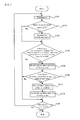
- FIG. 7 is a flowchart conceptually showing a flow of operations of the pre-equalizer 14 and the waveform distortion correction circuit 18 .
- FIG. 8 is a block diagram conceptually showing the structure of the waveform distortion correction circuit 18 .
- FIG. 9 is a waveform chart conceptually showing an operation of correcting the waveform distortion by the waveform distortion correction circuit 18 , on the sample value series RS C .
- step S 101 an operation of reproducing data recorded on the optical disc 100 is performed.
- the reproduction operation it is judged whether or not the signal level of a minT space (and more specifically, the signal level of the peak of the minT space, i.e. the maximum signal level of the minT space) is less than or equal to the zero level (step S 102 ).
- this judgment is an operation example when the zero level is used as the reference level, and if the reference level is not the zero level, then it is judged whether or not the signal level of the minT space is less than or equal to the reference level.
- this judgment is an operation example in a case where it is aimed at the optical disc 100 in which the reflectance of the laser beam LB is reduced by forming the marks. Therefore, if it is aimed at the optical disc 100 in which the reflectance of the laser beam LB is increased by forming the marks, it is judged whether or not the signal level of the minT space (and more specifically, the signal level of the peak of the minT space, i.e. the minimum signal level of the minT space) is greater than or equal to the zero level (or the reference level).
- the minT indicates the read signal R RF corresponding to the record data with the shortest run length (and more specifically, the read sample value series RS C corresponding to the read signal R RF ).
- the minT indicates the read signal R RF corresponding to the record data with a run length of 3T.
- the minT indicates the read signal R RF corresponding to the record data with a run length of 2T.
- step S 102 if it is judged that the signal level of the minT space is not less than or equal to the zero level (the step S 102 : No), the operational flow goes to a step S 104 .
- the pre-equalizer 14 increases the amplification factor (step S 103 ).
- the pre-equalizer 14 preferably increases the reference amplification factor set in advance for the pre-equalizer 14 , by approximately 1 dB to 3 dB. Specifically, for example, if the reference amplification factor set in advance for the pre-equalizer 14 is 5 dB, it is preferable to remove the intersymbol interference (in other words, to perform waveform-shaping) from the read sample value series RS, by using an amplification factor of approximately 6 dB to 8 dB.
- the pre-equalizer 14 preferably increases the aforementioned amplification factor when performing the waveform-shaping on a signal component which is at the frequency of the read signal R RF corresponding to the record data with the shortest run length or which is in the vicinity of this frequency.
- the pre-equalizer 14 preferably uses the aforementioned reference amplification factor (i.e. does not increase the amplification factor) when performing the waveform-shaping on a signal component other than the signal component which is at the frequency of the read signal R RF corresponding to the record data with the shortest run length or which is in the vicinity of this frequency.
- the predetermined threshold value is preferably set on the basis of whether or not the preferable reproduction is performed. Specifically, it is preferable to set the value of the symbol error rate which does not allow the preferable reproduction operation (e.g. approximately 0.001 or more), as the predetermined threshold value.
- the operational flow goes to a step S 109 .
- step S 104 if it is judged that the symbol error rate is greater than or equal to the threshold value, or that the error correction is unable to be performed, or that the synchronization data is unable to be read (the step S 104 : Yes), then, the waveform distortion of the long mark is measured (step S 105 ).
- a waveform distortion ratio i.e. D/A ⁇ 100 which indicates a ratio of the waveform distortion amount D (or D′) to the maximum amplitude A of the read signal R RF .
- step S 106 it is judged whether or not the waveform distortion is greater than or equal to a predetermined value. For example, it is judged whether or not the waveform distortion ratio is greater than or equal to approximately 30%.
- the operational flow goes to the step S 109 .
- a waveform distortion correction condition such as a correction level and a correction range for the waveform distortion, is set (step S 107 ).
- the waveform distortion correction condition will be detailed later (refer to FIG. 9 and the like).
- step S 108 the waveform distortion of the long mark is corrected on the basis of the waveform distortion correction condition set in the step S 107 (step S 108 ).
- step S 109 it is judged whether or not the reproduction operation is to be ended (step S 109 ), and if the reproduction operation is not to be ended (the step S 109 : No), the operational flow returns to the step S 101 , and the operations after the step S 101 are repeated again.
- the operation about the correction of the waveform distortion is performed mainly by the waveform distortion correction circuit 18 .
- the specific circuit structure of the waveform distortion correction circuit will be described.
- the waveform distortion correction circuit 18 is provided with a delay adjustment circuit 181 , a distortion correction value detection circuit 182 , a mark/space length detection circuit 183 , a timing generation circuit 184 , and a selector 185 .
- the read sample value series RS C outputted from the pre-equalizer 14 is outputted to each of the delay adjustment circuit 181 , the distortion correction value detection circuit 182 , and the mark/space length detection circuit 183 .
- the distortion correction value detection circuit 182 holds a sample value S(k) at a time point which is a time corresponding to minT after the zero cross point and outputs it as a distortion correction value and to the selector 185 .
- the delay adjustment circuit 181 sets a delay amount corresponding to the longest run length of the record data and outputs the read sample value series RS C to the selector 185 in desired timing. Specifically, if the optical disc 100 is a Blu-ray Disc, the delay adjustment circuit 181 sets a delay amount corresponding to the longest run length of 9T, and if the optical disc 100 is a DVD, the delay adjustment circuit 181 sets a delay amount corresponding to the longest run length of 14T.
- the mark/space length detection circuit 183 detects a mark/space length by detecting an interval between the zero cross points, the number of continuous coded bits, and the like. The detection result is outputted to the timing generation circuit 184 .
- the timing generation circuit 184 generates a timing signal SW on the basis of the mark/space length detected on the mark/space length detection circuit 183 and outputs the generated timing signal SW to the selector 185 .
- SW high-level timing signal
- the selector 185 If the high-level timing signal SW is outputted from the timing generation circuit 184 , the selector 185 outputs the distortion correction value amd outputted from the distortion correction value detection circuit 182 , to the limit equalizer 15 as the distortion-corrected read sample value series RS CAM . On the other hand, if the low-level timing signal SW is outputted from the timing generation circuit 184 , the selector 185 outputs the read sample value series RS C outputted from the delay adjustment circuit 181 , to the limit equalizer 15 as the distortion-corrected read sample value series RS CAM .
- the waveform distortion correction condition set in the step S 107 in FIG. 7 substantially corresponds to the distortion correction value amd detected on the distortion correction value detection circuit 182 and the timing signal SW generated on the timing generation circuit 184 .
- sample values included in the sample value series RS C are corrected to the distortion correction value amd detected on the distortion correction value detection circuit 182 .
- the waveform distortion is corrected.
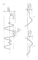
- FIG. 10 is a waveform chart conceptually showing a waveform or the like of the read signal R RF before and after the correction of the waveform distortion.
- FIG. 11 are waveform charts conceptually showing the operation of obtaining the high-frequency emphasized read sample value series RS H , on the sample value series RS C , in each of a case where the waveform distortion is not corrected and a case where the waveform distortion is corrected.
- FIG. 12 is a graph showing a change in symbol error rate with respect to the waveform distortion ratio.
- the binary waveform after binarizing the read signal R RF includes an error signal caused by the waveform distortion. This results in inconsistency with the original record data and causes a binary error.
- the binary waveform after binarizing the read signal R RF no longer includes the error signal caused by the waveform distortion. This results in consistency with the original record data and does not cause the binary error.
- the waveform distortion likely has a signal level which is greater than the lower limit ⁇ L of the amplitude limit value on the limit equalizer 15 .
- R SH S(0)+k ⁇ ( ⁇ 2 ⁇ L+Sip(0)+Sip(1)).
- This increases the value of the high-frequency emphasized read sample value series RS H , by the value obtained by multiplying the sum of the lower limit ⁇ L, Sip(0), and Sip(1) by K.
- This is not preferable because it emphasizes the waveform distortion which is originally not to occur.
- the emphasized waveform distortion likely leads to such a disadvantage that the mark with a relatively long run length in which the waveform distortion occurs is misjudged to be another mark in an information reproducing apparatus which adopts the PRML. This results in the binary error.
- R SH S(0)+k ⁇ ( ⁇ 2 ⁇ L+Sip(0)+Sip(1)).
- the signal level of the waveform distortion can be corrected to be a signal level which is less than or equal to the lower limit ⁇ L of the amplitude limit value on the limit equalizer 15 .
- the effect by correcting the waveform distortion can be also seen from a change in symbol error rate with respect to the waveform distortion ratio.
- the value of SER in the case where the waveform distortion is corrected is improved, compared to the value of SER in the case where the waveform distortion is not corrected.
- the dispersion of the sample values before and after the reference sample point is forcibly controlled in the read signal which causes the intersymbol interference in the high-frequency emphasis.
- the intersymbol interference does not occur.
- the amplitude limit and the high-frequency emphasis are performed on the limit equalizer 15 after the waveform distortion is corrected.
- the waveform distortion which is originally not to occur is emphasized on the limit equalizer 15 .
- the waveform distortion rarely causes the binary error, and this allows the preferable reproduction operation.
- FIG. 13 are graphs showing a change in symbol error rate with respect to asymmetry, in each of a case where the amplification factor is not increased and a case where the amplification factor is not increased.
- FIG. 14 are graphs showing a change in symbol error rate with respect to the amplification factor, in each of the case where the waveform distortion is corrected and the case where the waveform distortion is not corrected.
- FIG. 15 is a waveform chart conceptually showing a waveform of the read signal R RF corresponding to minT according to a change in asymmetry.
- FIG. 16 is a waveform chart conceptually showing another waveform or the like of the read signal R RF before and after the correction of the waveform distortion.
- the reference amplification factor of the pre-equalizer 14 i.e. the amplification factor when the amplification factor is not increased
- the reference amplification factor of the pre-equalizer 14 is 5 dB.
- the symbol error rate in the case where the amplification factor is increased to 7.4 dB is improved, compared to the symbol error rate in the case where the amplification factor is not increased (i.e. in the case where the amplification factor is 5.0 dB),
- the symbol error rate in the case where the amplification factor is increased to 7.4 dB is deteriorated, compared to the symbol error rate in the case where the amplification factor is not increased (i.e. in the case where the amplification factor is 5.0 dB).
- This is caused by the amplified waveform distortion due to the increase of the amplification factor. Therefore, it is extremely preferable to perform the waveform distortion in the case where the amplification factor is increased.
- the symbol error rate can be improved.
- the symbol error rate is improved compared to the symbol error rate in the case where the amplification factor of the pre-equalizer 14 is not increased (i.e. where the amplification factor is 5.0 dB), by increasing the amplification factor of the pre-equalizer 14 by approximately 1 dB to 3 dB.
- the symbol error rate is deteriorated, compared to the symbol error rate in the case where the amplification factor of the pre-equalizer 14 is not increased.
- the deterioration of the symbol error rate is caused by that the waveform distortion is the excessively emphasized due to the excessively increased amplification factor and thereby the mark with a relatively long run length, in which the waveform distortion occurs, is misjudged to be another mark.
- the improvement of the reproduction properties e.g. the symbol error rate
- the amplification factor of the pre equalizer 14 can be explained from the following reasons.
- the signal level of the minT space is greater than the signal level of the minT mark.
- the signal waveform of minT is gradually shifted to the lower side (i.e. negative side), with respect to an all T center level (i.e. the reference level or the zero level). If the asymmetry increases to some degree, the signal level of the peak of the minT space likely falls below the all T center level. In this case, the minT is likely misjudged to be the waveform distortion.
- FIG. 16 since the minT is corrected as the waveform distortion, a signal corresponding to the minT does not appear in the binary signal, which leads to the deterioration of the symbol error rate.
- the signal level of the minT space is less than the signal level of the minT mark.
- the signal waveform of minT is gradually shifted to the upper side (i.e. positive side), with respect to the all T center level (i.e. the reference level or the zero level). If the asymmetry increases to some degree, the signal level of the peak of the minT space likely exceeds the all T center level. In this case, the minT is likely misjudged to be the waveform distortion. As a result, since the minT is corrected as the waveform distortion, the signal corresponding to the minT does not appear in the binary signal, which leads to the deterioration of the symbol error rate.
- the signal waveform of the minT can be shifted by increasing the amplification factor of the pre-equalizer 14 (in particular, by increasing the amplification factor with respect to the signal component which is at the frequency of the read signal R RF corresponding to the record data with the shortest run length and which is in the vanity of the frequency).
- the signal level of the peak of the minT space described above falls below or exceeds the all T center level.
- FIG. 17 is a flowchart conceptually showing another flow of operations of the pre-equalizer 14 and the waveform distortion correction circuit 18 .
- step S 101 the operation of reproducing data recorded on the optical disc 100 is performed.
- step S 102 it is judged whether or not the signal level of the minT space is less than or equal to the zero level.
- step S 102 if it is judged that the signal level of the minT space is not less than or equal to the zero level (the step S 102 : No), the operational flow goes to a step S 104 .
- the pre-equalizer 14 increases the amplification factor (step S 103 ).
- SER symbol error rate
- the operational flow goes to a step S 109 .
- step S 104 if it is judged that the symbol error rate is greater than or equal to the threshold value, or that the error correction is unable to be performed, or that the synchronization data is unable to be read (the step S 104 : Yes), then, the waveform distortion of the long mark is measured (step S 105 ). Then, it is judged whether or not the waveform distortion is greater than or equal to a predetermined value (step S 106 ).
- the operational flow goes to the step S 109 .
- step S 106 if it is judged that the waveform distortion is greater than or equal to the predetermined value (e.g. that the waveform distortion ratio is greater than or equal to approximately 30%) (the step S 106 : Yes), then, a waveform distortion correction condition #x (wherein x is an integer of 1 or more, with an initial value of 1), such as a correction level and a correction range for the waveform distortion, is set (step S 201 ). Then, on the basis of the waveform distortion correction condition #x set in the step S 201 , the waveform distortion of the long mark is corrected (step S 108 ).
- the predetermined value e.g. that the waveform distortion ratio is greater than or equal to approximately 30%
- step S 202 it is judged whether or not a target condition is realized.
- the target condition for example, the judgment condition in the step S 102 (i.e. that the symbol error rate is greater than or equal to the predetermined threshold value, or that the error correction is unable to be performed) may be used.
- step S 202 if it is judged that the target condition is realized (the step S 202 : Yes), the operational flow goes to the step S 109 .
- step S 202 if it is judged that the target condition is not realized (the step S 202 : No), x is incremented by 1 (step S 203 ), and then, the operations after the step S 201 are repeated. In other words, until the target condition is realized, the waveform distortion is corrected while the waveform distortion correction condition is changed as occasion demands.
- the waveform distortion correction conditions it is preferable to use the waveform distortion correction conditions used in the operations in modified examples detailed later with reference to FIG. 19 to FIG. 32 .
- FIG. 18 is a flowchart conceptually showing another flow of operations of the pre-equalizer 14 and the waveform distortion correction circuit 18 .
- step S 101 the operation of reproducing data recorded on the optical disc 100 is performed.
- a variable n used in increasing the amplification factor of the pre-equalizer 14 is set to an initial value 0 (step S 401 ).
- step S 102 it is judged whether or not the signal level of the minT space is less than or equal to the zero level.
- step S 102 if it is judged that the signal level of the minT space is not less than or equal to the zero level (the step S 102 : No), the operational flow goes to a step S 104 .
- step S 102 if it is judged that the signal level of the minT space is less than or equal to the zero level (the step S 102 : Yes), the variable n is incremented by 1 (step S 402 ), and then, the amplification factor of the pre-equalizer 14 is increased by n dB (step S 403 ).
- SER symbol error rate
- the operational flow goes to a step S 109 .
- step S 104 if it is judged that the symbol error rate is greater than or equal to the threshold value, or that the error correction is unable to be performed, or that the synchronization data is unable to be read (the step S 104 : Yes), then, the waveform distortion of the long mark is measured (step S 105 ). Then, it is judged whether or not the waveform distortion is greater than or equal to a predetermined value (step S 106 ).
- the step S 106 if it is judged that the waveform distortion is not greater than or equal to the predetermined value (e.g. that the waveform distortion ratio is less than or equal to approximately 30%) (the step S 106 : No), then, it is judged whether or not the retry number is greater than or equal to a predetermined value, wherein the retry number is the number of times to increase the amplification factor of the pre-equalizer 14 (step S 404 ).
- the predetermined value here may be set on the basis of a relation between the initial value and the maximum value of the amplification factor of the pre-equalizer 14 and an increase amount when the amplification factor is increased once.
- the predetermined value may be set to be (A 2 ⁇ A 1 )/a.
- the operational flow returns to the step S 102 , and the operations after the step S 102 are repeated.
- step S 404 if it is judged that the retry number is greater than or equal to the predetermined value (the step S 404 : Yes), the operational flow goes to the step S 109 .
- step S 106 if it is judged that the waveform distortion is greater than or equal to the predetermined value (e.g. that the waveform distortion ratio is greater than or equal to approximately 30%) (the step S 106 : Yes), then, a waveform distortion correction condition, such as a correction level and a correction range for the waveform distortion, is set (step S 107 ). Then, the waveform distortion of the long mark is corrected on the basis of the waveform distortion correction condition set in the step S 107 (step S 108 ).
- the predetermined value e.g. that the waveform distortion ratio is greater than or equal to approximately 30%
- step S 109 it is judged whether or not the reproduction operation is to be ended (step S 109 ), and if the reproduction operation is not to be ended (the step S 109 : No), the operational flow returns to the step S 101 , and the operations after the step S 101 are repeated again.
- FIG. 19 is a waveform chart conceptually showing an operation of correcting the waveform distortion by a waveform distortion correction circuit 18 a provided for the information reproducing apparatus 1 a in the first modified example, on the sample value series RS C .
- FIG. 20 is a block diagram conceptually showing the structure of the waveform distortion correction circuit 18 a provided for the information reproducing apparatus 1 a in the first modified example.
- the average value of center samples of a mark with a run length of (min+3)T i.e. the minimum amplitude value of the mark with (min+3)T for the waveform distortion shown in FIG. 5( a ) to FIG. 5( c )
- the maximum amplitude value of the mark with (min+3)T for the waveform distortion shown in FIG. 6( a ) to FIG. 6( c ) is used.
- (min+k)T indicates the read signal R RF (and more specifically, the read sample value series RS C corresponding to the read signal R RF ) corresponding to the record data with the (k+1)th shortest run length (wherein k is an integer or 1 or more). Therefore, (min+3)T indicates the read signal R RF (and more specifically, the read sample value series RS C corresponding to the read signal R RF ) corresponding to the record data with the fourth shortest run length. For example, if the optical disc 100 is a DVD, (min+3)T indicates the read signal R RF corresponding to the record data with a run length of 6T. For example, if the optical disc 100 is a Blu-ray Disc, (min+3)T indicates the read signal R RF corresponding to the record data with a run length of 5T.
- the waveform distortion correction circuit 18 a is provided with the delay adjustment circuit 181 , a distortion correction value detection circuit 182 a , the mark/space length detection circuit 183 , the timing generation circuit 184 , and the selector 185 .
- the distortion correction value detection circuit 182 a holds and averages the center sample values of the record data if the record data with a run length of (min+3)T is inputted, while monitoring the mark/space length outputted from the mark/space length detection circuit 183 , and outputs it to the selector 185 as the distortion correction value.
- the signal level after the correction is increased from the original signal level (i.e. the signal level before the correction).
- the waveform distortion it is possible to bring the signal level closer to the maximum amplitude of the read signal R RF .
- the record data can be reproduced more preferably.
- the average value of the center samples of the record data with another run length may be used.
- the record data which can realize the maximum amplitude is preferably used as the record data with another run length.
- FIG. 21 is a waveform chart conceptually showing an operation of correcting the waveform distortion by a waveform distortion correction circuit 18 b provided for the information reproducing apparatus 1 b in the second modified example, on the sample value series RS C .
- FIG. 22 is a block diagram conceptually showing the structure of the waveform distortion correction circuit 18 b provided for the information reproducing apparatus 1 b in the second modified example.
- the maximum value or minimum value of a digital code for indicating the read sample value series RS H i.e. the minimum value of the digital code for the waveform distortion shown in FIG. 5( a ) to FIG. 5( c ), and the minimum value of the digital code for the waveform distortion shown in FIG. 6( a ) to FIG. 6( c )
- the digital code is 8-bit
- the waveform distortion correction circuit 18 b is provided with the delay adjustment circuit 181 , a distortion correction value detection circuit 182 b , the mark/space length detection circuit 183 , the timing generation circuit 184 , and the selector 185 .
- the distortion correction value detection circuit 182 b outputs the maximum value or minimum value of the digital code, to the selector 185 as the distortion correction value.
- the distortion correction value amd it is possible to preferably receive the aforementioned various effects while relatively reducing the load of the waveform distortion correction circuit 18 b (i.e. the load of the information reproducing apparatus 1 b ).
- FIG. 23 is a waveform chart conceptually showing an operation of correcting the waveform distortion by a waveform distortion correction circuit 18 c provided for the information reproducing apparatus 1 c in the third modified example, on the sample value series RS C .
- FIG. 24 is a block diagram conceptually showing the structure of the waveform distortion correction circuit 18 c provided for the information reproducing apparatus 1 c in the third modified example.
- the upper limit L or lower limit ⁇ L of the amplitude limit value on the limit equalizer 15 i.e. the lower limit ⁇ L of the amplitude limit value for the waveform distortion shown in FIG. 5( a ) to FIG. 5( c ), and the upper limit L of the amplitude limit value for the waveform distortion shown in FIG. 3( a ) to FIG. 6( c ) is used.
- the waveform distortion correction circuit 18 c is provided with the delay adjustment circuit 181 , the mark/space length detection circuit 183 , the timing generation circuit 184 , and the selector 185 .
- the selector 185 outputs the upper limit L or lower limit ⁇ L of the amplitude limit value on the limit equalizer 15 as the distortion correction sample value series RS CAM if the high-level timing signal SW is outputted from the timing generation circuit 184 .
- the signal level of the waveform distortion is corrected to the upper limit L or lower limit ⁇ L of the amplitude limit value on the limit equalizer 15 , it is certainly possible to prevent such a disadvantage that the waveform distortion which is originally not to occur is emphasized. Moreover, it is also possible to preferably prevent such a disadvantage that the mark with a relatively long run length is misjudged to be another mark, caused by the emphasized waveform distortion, in the information reproducing apparatus which adopts the PRML. As a result, the binary error caused by the waveform distortion hardly occurs, which allows the preferable reproduction operation.
- a value which is greater than or equal to the upper limit L or a value which is less than or equal to the lower limit ⁇ L of the amplitude limit value on the limit equalizer 15 may be used. Even in such construction, it is possible to preferably receive the aforementioned various effects.
- FIG. 25 is a waveform chart conceptually showing an operation of correcting the waveform distortion by a waveform distortion correction circuit 18 d provided for the information reproducing apparatus 1 d in the fourth modified example, on the sample value series RS C .
- FIG. 26 is a block diagram conceptually showing the structure of the waveform distortion correction circuit 18 d provided for the information reproducing apparatus 1 d in the fourth modified example.
- a value i.e. 2L or ⁇ 2L which is twice the upper limit L or lower limit ⁇ L of the amplitude limit value on the limit equalizer 15 (i.e. the lower limit ⁇ L of the amplitude limit value for the waveform distortion shown in FIG. 5( a ) to FIG. 5( c ), and the upper limit L of the amplitude limit value for the waveform distortion shown in FIG. 6( a ) to FIG. 6( c )) is used.
- the waveform distortion correction circuit 18 d is provided with the delay adjustment circuit 181 , an amplifier 182 d , the mark/space length detection circuit 183 , the timing generation circuit 184 , and the selector 185 .
- the amplifier 182 d amplifies the upper limit L or lower limit ⁇ L of the amplitude limit value on the limit equalizer 15 by two times, and then outputs it to the selector 185 as the distortion correction value amd.
- the signal level of the waveform distortion is corrected to the upper limit L or lower limit ⁇ L of the amplitude limit value on the limit equalizer 15 , it is certainly possible to prevent such a disadvantage that the waveform distortion which is originally not to occur is emphasized. Moreover, it is also possible to preferably prevent such a disadvantage that the mark with a relatively long run length is misjudged to be another mark, caused by the emphasized waveform distortion, in the information reproducing apparatus which adopts the PRML. As a result, the binary error caused by the waveform distortion hardly occurs, which allows the preferable reproduction operation.
- the signal level of the waveform distortion is corrected to the signal level which is less than or equal to the value which is twice the upper limit L or the lower limit ⁇ L of the amplitude limit value, it is certainly possible to prevent such a disadvantage that the waveform distortion is less than or equal to the upper limit L of the amplitude limit value or is greater than or equal to the lower limit ⁇ L.
- the binary error caused by the waveform distortion hardly occurs, which allows the preferable reproduction operation.
- FIG. 27 is a timing chart conceptually showing an operation of correcting the waveform distortion by a waveform distortion correction circuit 18 e provided for the information reproducing apparatus 1 e in the fifth modified example, on a first read signal R RF .
- FIG. 28 is a timing chart conceptually showing the operation of correcting the waveform distortion by the waveform distortion correction circuit 18 e provided for the information reproducing apparatus 1 e in the fifth modified example, on a second read signal R RF .
- FIG. 29 is a flowchart conceptually showing a first flow of operations by the waveform distortion correction circuit 18 e provided for the information reproducing apparatus 1 e in the fifth modified example.
- FIG. 30 is a flowchart conceptually showing a second flow of operations by the waveform distortion correction circuit 18 e provided for the information reproducing apparatus 1 e in the fifth modified example.
- the record data recorded on the optical disc 100 includes not only normal user data but also the synchronization data (e.g. the record data with a run length of 14T if the optical disc 100 is a DVD, and the record data with a run length of 9T if the optical disc 100 is a Blu-ray Disc) used for synchronization in reproducing the user data.
- the synchronization data is included in the record data, the correction of the waveform distortion may be limited to the synchronization data.
- the optical disc 100 is a Blu-ray Disc
- the synchronization data is formed of a 9T mark and a 9T space
- the waveform distortion before or after the detected 9T space may be corrected.
- the waveform distortion may be corrected near a position being shifted by a time corresponding to 1932T (or 1932T ⁇ 1: ⁇ 1 is a predetermined constant) from the detected 9T space toward the advancing direction (or a position being shifted by ⁇ 1T from the relevant position toward the advancing direction: ⁇ 1 is a predetermined constant).
- the optical disc 100 is a DVD
- the synchronization data is a 14T mark or a 14T space
- the 14T space is detected, and the waveform distortion may be corrected near a position being shifted by a time corresponding to 1488T (or 1488T ⁇ 2: ⁇ 2 is a predetermined constant) from the detected 14T space toward the advancing direction (or a position being shifted by ⁇ 2T from the relevant position toward the advancing direction: ⁇ 2 is a predetermined constant).
- step S 101 the operation of reproducing data recorded on the optical disc 100 is performed.
- step S 102 it is judged whether or not the signal level of the minT space is less than or equal to the zero level.
- step S 102 if it is judged that the signal level of the minT space is not less than or equal to the zero level (the step S 102 : No), the operational flow goes to a step S 301 .
- the pre-equalizer 14 increases the amplification factor (step S 103 ).
- a sync space i.e. a space which constitutes the synchronization data: the aforementioned 9T space, 14T space, and the like.
- step S 301 if it is judged that the sync space is not detected (the step S 301 : No), the operational flow returns to the step S 301 , and the operation of judging whether or not the sync space is detected is repeated.
- step S 301 if it is judged that the sync space is detected (the step S 301 : Yes), then, it is judged whether or not the mark is reproduced at a position being shifted by a time corresponding to nT from the sync space toward the advancing direction (step S 302 ). In other words, focusing on the periodicity that the synchronization data appears, it is judged whether or not the mark is reproduced at a position being shifted by the aforementioned time corresponding to 1932T ⁇ 1 or 1488T ⁇ 2 from the detected sync space toward the advancing direction.
- step S 302 if it is judged that the mark is not reproduced at the position being shifted by the time corresponding to nT from the sync space toward the advancing direction (the step S 302 : No), the operation in the step S 302 is repeated.
- step S 302 if it is judged that the mark is reproduced at the position being shifted by the time corresponding to nT from the sync space toward the advancing direction (the step S 302 : Yes), then, the waveform distortion of the mark corresponding to the synchronization data is measured near the position being shifted by the time corresponding to nT from the sync space toward the advancing direction (step S 105 ). Subsequently, the same operations shown in FIG. 7 are performed.
- a plurality of waveform distortion correction conditions may be set, and the waveform distortion correction may be performed by applying the waveform distortion correction conditions in order.
- step S 101 the operation of reproducing data recorded on the optical disc 100 is performed.
- step S 102 it is judged whether or not the signal level of the minT space is less than or equal to the zero level.
- step S 102 if it is judged that the signal level of the minT space is not less than or equal to the zero level (the step S 102 : No), the operational flow goes to a step S 301 .
- the pre-equalizer 14 increases the amplification factor (step S 103 ).
- step S 301 it is judged whether or not the sync space (i.e. the space which constitutes the synchronization data: the aforementioned 9T space, 14T space, and the like) is detected (step S 301 ).
- the sync space i.e. the space which constitutes the synchronization data: the aforementioned 9T space, 14T space, and the like
- step S 301 if it is judged that the sync space is not detected (the step S 301 : No), the operational flow returns to the step S 301 , and the operation of judging whether or not the sync space is detected is repeated.
- step S 302 if it is judged that the mark is not reproduced at the position being shifted by the time corresponding to nT from the sync space toward the advancing direction (the step S 302 : No), the operation in the step S 302 is repeated.
- step S 302 if it judged that the mark is reproduced at the position being shifted by the time corresponding to nT from the sync space toward the advancing direction (the step S 302 : Yes), then, the waveform distortion of the mark corresponding to the synchronization data is measured near the position being shifted by the time corresponding to nT from the sync space toward the advancing direction (step S 105 ). Subsequently, the same operations shown in FIG. 17 are performed.
- FIG. 31 is a block diagram conceptually showing the structure of a waveform distortion correction circuit 18 f provided for the information reproducing apparatus 11 in a sixth modified example.
- FIG. 32 is a block diagram conceptually showing the structure of a waveform distortion detection circuit 186 f provided for the waveform distortion correction circuit 18 f provided for the information reproducing apparatus if in the sixth modified example.
- the waveform distortion correction circuit 18 f is provided with the delay adjustment circuit 181 , a waveform distortion detection circuit 186 f , the mark/space length detection circuit 183 , the timing generation circuit 184 , the selector 185 , and an AND circuit 187 f.
- a result of the detection of the mark/space length by the mark/space length detection circuit 183 is outputted to the waveform distortion detection circuit 186 f , in addition to the timing generation circuit 184 .
- the AND circuit 187 f generates a high-level timing signal SW 0 if the waveform distortion is detected (if each of the timing signal SW outputted from the timing generation circuit 184 and the waveform distortion detection signal DT outputted from the waveform distortion detection circuit 186 f is high-level), on the basis of the output of each of the timing generation circuit 184 and the waveform distortion detection circuit 186 f .
- the AND circuit 187 f generates a low-level timing signal SW 0 if the waveform distortion is not detected (if either the timing signal SW outputted from the timing generation circuit 184 or the waveform distortion detection signal DT outputted from the waveform distortion detection circuit 186 f is low-level), on the basis of the output of each of the timing generation circuit 184 and the waveform distortion detection circuit 186 f .
- the waveform distortion is corrected selectively when the waveform distortion is detected.
- the waveform distortion detection circuit 186 f is provided with a shift register 1831 f , a selector 1832 f , a maximum value detection circuit 1833 f , a minimum value detection circuit 1834 f , a subtracter 1835 f , and a judgment circuit 1836 f.
- the read sample value series RS C inputted to the waveform distortion detection circuit 186 f is outputted to the shift register 1831 f .
- the shift register 1831 f outputs the inputted read sample value series RS C to the selector 1832 f as outputs D 0 to D 14 while shifting the inputted read sample value series RS C by one clock.
- the selector 1832 f selectively samples and holds three outputs from among the outputs D 0 to D 14 , on the basis of the mark/space length, in timing outputted from the mark/space length detection circuit 183 , and outputs the three outputs to a distortion correction amount detection circuit 1837 f , the maximum value detection circuit 1833 f , and the minimum value detection circuit 1834 f , respectively.
- the selector 1832 f selectively samples and holds three outputs D 2 , D 3 , and D 4 from among the outputs D 0 to D 14 if the mark/space length outputted from the mark/space length detection circuit 183 is 6T, and outputs the three outputs to the distortion correction amount detection circuit 1837 f , the maximum value detection circuit 1833 f , and the minimum value detection circuit 1834 f , respectively.
- the selector 1832 f selectively samples and holds three outputs D 2 , D 3 , and D 5 from among the outputs D 0 to D 14 if the mark/space length outputted from the mark/space length detection circuit 183 is 7T, and outputs the three outputs to the distortion correction detection circuit 1837 f , the maximum value detection circuit 1833 f , and the minimum value detection circuit 1834 f , respectively.
- the selector 1832 f selectively samples and holds three outputs D 2 , D 4 , and D 6 from among the outputs D 0 to D 14 if the mark/space length outputted from the mark/space length detection circuit 183 is 8T, and outputs the three outputs to the distortion correction amount detection circuit 1837 f , the maximum value detection circuit 1833 f , and the minimum value detection circuit 1834 f , respectively.
- the selector 1832 f selectively samples and holds three outputs D 2 , D 4 , and D 7 from among the outputs D 0 to D 14 if the mark/space length outputted from the mark/space length detection circuit 183 is 9T, and outputs the three outputs to the distortion correction amount detection circuit 1837 f , the maximum value detection circuit 1833 f , and the minimum value detection circuit 1834 f , respectively.
- the selector 1832 f selectively samples and holds three outputs D 2 , D 5 , and D 8 from among the outputs D 0 to D 14 if the mark/space length outputted from the mark/space length detection circuit 183 is 10T, and outputs the three outputs to the distortion correction amount detection circuit 1837 f , the maximum value detection circuit 1833 f , and the minimum value detection circuit 1834 f , respectively.
- the selector 1832 f selectively samples and holds three outputs D 2 , D 5 , and D 9 from among the outputs D 0 to D 14 if the mark/space length outputted from the mark/space length detection circuit 183 is 11T, and outputs the three outputs to the distortion correction amount detection circuit 1837 f , the maximum value detection circuit 1833 f , and the minimum value detection circuit 1834 f , respectively.
- the selector 1832 f selectively samples and holds three outputs D 2 , D 7 , and D 12 from among the outputs D 0 to D 14 if the mark/space length outputted from the mark/space length detection circuit 183 is 14T, and outputs the three outputs to the distortion correction amount detection circuit 1837 f , the maximum value detection circuit 1833 f , and the minimum value detection circuit 1834 f , respectively.
- the operation of the selector 1832 f described above substantially corresponds to the operation of selectively outputting the signal level in the front edge portion, the signal level in the middle portion, and the signal level in the rear edge portion of the waveform distortion, shown in FIG. 5( a ) to FIG. 5( c ) and FIG. 6( a ) to FIG. 6( c ).
- desired one signal level of the three outputs outputted from the selector 1832 f i.e. the signal level in the front edge portion, the signal level in the middle portion, and the signal level in the rear edge portion
- the distortion correction value amd is outputted as the distortion correction value amd.
- the signal level in the front edge portion or the signal level in the rear edge portion is outputted as the distortion correction value amd.
- the signal level in the rear edge portion is outputted as the distortion correction value amd.
- the signal level in the front edge portion is outputted as the distortion correction value amd.
- the maximum value detection circuit 1833 f the maximum value (i.e. the maximum signal level) of the three outputs outputted from the selector 1832 f is detected, and the detected maximum value is outputted to the subtracter 1835 f.
- the minimum value detection circuit 1834 f the minimum value (i.e. the minimum signal level) of the three outputs outputted from the selector 1832 f is detected, and the detected minimum value is outputted to the subtracter 1835 f.
- the minimum value detected on the minimum value detection circuit 1834 f is subtracted from the maximum value detected on the maximum value detection circuit 1833 f , by which the waveform distortion amount D is calculated.
- the judgment circuit 1836 f it is judged whether or not the waveform distortion amount outputted from the subtracter 1835 f is greater than or equal to a predetermined value x. If the waveform distortion amount D is relatively small, the waveform distortion is not regarded as being detected, and the low-level waveform distortion detection signal DT is outputted. On the other hand, if the waveform distortion amount D is relatively large (e.g. if the waveform distortion ratio is greater than or equal to approximately 30%), the waveform distortion is regarded as being detected, and the high-level waveform distortion detection signal DT is outputted.
- the signal level of the waveform distortion can be corrected to desired one of the signal level in the front edge portion, the signal level in the middle portion, and the signal level in the rear edge portion.
- the signal level of the waveform distortion is corrected to the signal level in the front edge portion.
- the waveform distortion in which the signal level in the front edge portion is changed, as shown in FIG. 5( b ) and FIG. 6( b ) cannot be preferably corrected.
- this type of waveform distortion can be preferably corrected.
- the waveform distortion occurs generally due to the dispersion of the shape, length, and the like of the marks formed on the recording surface of the optical disc 100 . Therefore, the waveform distortion tends to occur in the recording type optical disc 100 , such as a DVD-R/RW, a DVD+R/RW, a DVD-RAM, and a BD-R/RE.
- the waveform distortion occurs if the synchronization data formed of the relatively long mark is adjacent to each other in a tracking direction, as shown in FIG. 33 .
- the correction can be preferably made, obviously.
Landscapes
- Engineering & Computer Science (AREA)
- Signal Processing (AREA)
- Signal Processing For Digital Recording And Reproducing (AREA)
- Optical Recording Or Reproduction (AREA)
Abstract
Description
- Patent document 1: Japanese Patent No. 3459563
- 1, 2 information reproducing apparatus
- 10 spindle motor
- 11 pickup
- 12 HPF
- 13 A/D converter
- 14 pre-equalizer
- 15 limit equalizer
- 16 binary circuit
- 17 decoding circuit
- 18 waveform distortion correction circuit
- 181 delay adjustment circuit
- 182 distortion-correction-value detection circuit
- 183 mark/space length detection circuit
- 184 timing generation circuit
- 185 selector
- 186 waveform distortion detection circuit
- 151 amplitude limit value setting block
- 1516 averaging circuit
- 152 amplitude limit block
- 1522 interpolation filter
- 1523 limiter
- 153 high-frequency emphasis block
Claims (10)
Applications Claiming Priority (1)
| Application Number | Priority Date | Filing Date | Title |
|---|---|---|---|
| PCT/JP2006/324282 WO2008068855A1 (en) | 2006-12-05 | 2006-12-05 | Information reproducing apparatus and method, and computer program |
Publications (2)
| Publication Number | Publication Date |
|---|---|
| US20100074080A1 US20100074080A1 (en) | 2010-03-25 |
| US8094534B2 true US8094534B2 (en) | 2012-01-10 |
Family
ID=39491774
Family Applications (1)
| Application Number | Title | Priority Date | Filing Date |
|---|---|---|---|
| US12/517,256 Expired - Fee Related US8094534B2 (en) | 2006-12-05 | 2006-12-05 | Information reproducing apparatus and method, and computer program |
Country Status (3)
| Country | Link |
|---|---|
| US (1) | US8094534B2 (en) |
| JP (1) | JP5031768B2 (en) |
| WO (1) | WO2008068855A1 (en) |
Citations (9)
| Publication number | Priority date | Publication date | Assignee | Title |
|---|---|---|---|---|
| US5570335A (en) * | 1994-05-23 | 1996-10-29 | Olympus Optical Co., Ltd. | Reproducing waveform correction circuit for optical information recording/reproducing system |
| JPH09330564A (en) | 1996-06-10 | 1997-12-22 | Matsushita Electric Ind Co Ltd | Digital information reproducing device |
| US5719843A (en) * | 1995-06-22 | 1998-02-17 | Matsushita Electric Industrial Co.Ltd | Method of maximum likelihood decoding and digital information playback apparatus |
| JP3459563B2 (en) | 1998-03-06 | 2003-10-20 | パイオニア株式会社 | Waveform equalizer and recorded information reproducing device |
| JP2003303474A (en) | 2002-04-05 | 2003-10-24 | Pioneer Electronic Corp | Disk evaluation device |
| US20050002316A1 (en) * | 2003-07-01 | 2005-01-06 | Sho Maruyama | Laser driver circuit with reduced noise and optical pickup circuit for use with the same |
| WO2005024822A1 (en) | 2003-09-02 | 2005-03-17 | Matsushita Electric Industrial Co., Ltd. | Reproduced signal processor and reproduced signal processing method |
| US20050063276A1 (en) * | 2003-09-19 | 2005-03-24 | Youichi Ogura | Optical disc device |
| US20070171564A1 (en) * | 2006-01-23 | 2007-07-26 | Toshiba Corporation | Disk drive servo |
Family Cites Families (2)
| Publication number | Priority date | Publication date | Assignee | Title |
|---|---|---|---|---|
| JPH0982028A (en) * | 1995-09-11 | 1997-03-28 | Toshiba Corp | Data reproduction circuit |
| JP2006040438A (en) * | 2004-07-28 | 2006-02-09 | Ricoh Co Ltd | Optical disk device |
-
2006
- 2006-12-05 WO PCT/JP2006/324282 patent/WO2008068855A1/en not_active Ceased
- 2006-12-05 US US12/517,256 patent/US8094534B2/en not_active Expired - Fee Related
- 2006-12-05 JP JP2008548141A patent/JP5031768B2/en not_active Expired - Fee Related
Patent Citations (12)
| Publication number | Priority date | Publication date | Assignee | Title |
|---|---|---|---|---|
| US5570335A (en) * | 1994-05-23 | 1996-10-29 | Olympus Optical Co., Ltd. | Reproducing waveform correction circuit for optical information recording/reproducing system |
| US5719843A (en) * | 1995-06-22 | 1998-02-17 | Matsushita Electric Industrial Co.Ltd | Method of maximum likelihood decoding and digital information playback apparatus |
| JPH09330564A (en) | 1996-06-10 | 1997-12-22 | Matsushita Electric Ind Co Ltd | Digital information reproducing device |
| JP3459563B2 (en) | 1998-03-06 | 2003-10-20 | パイオニア株式会社 | Waveform equalizer and recorded information reproducing device |
| JP2003303474A (en) | 2002-04-05 | 2003-10-24 | Pioneer Electronic Corp | Disk evaluation device |
| US20040257953A1 (en) | 2002-04-05 | 2004-12-23 | Hiroki Kuribayashi | Disk evaluation device |
| US20050002316A1 (en) * | 2003-07-01 | 2005-01-06 | Sho Maruyama | Laser driver circuit with reduced noise and optical pickup circuit for use with the same |
| WO2005024822A1 (en) | 2003-09-02 | 2005-03-17 | Matsushita Electric Industrial Co., Ltd. | Reproduced signal processor and reproduced signal processing method |
| US20050219985A1 (en) | 2003-09-02 | 2005-10-06 | Hiroyuki Nakahira | Reproduced signal processor and reproduced signal processing method |
| US20050063276A1 (en) * | 2003-09-19 | 2005-03-24 | Youichi Ogura | Optical disc device |
| US20070171564A1 (en) * | 2006-01-23 | 2007-07-26 | Toshiba Corporation | Disk drive servo |
| US7440224B2 (en) * | 2006-01-23 | 2008-10-21 | Toshiba Corporation | Disk drive servo |
Non-Patent Citations (1)
| Title |
|---|
| International Search Report, PCT/JP2006/324282, Mar. 13, 2007. |
Also Published As
| Publication number | Publication date |
|---|---|
| JP5031768B2 (en) | 2012-09-26 |
| WO2008068855A1 (en) | 2008-06-12 |
| US20100074080A1 (en) | 2010-03-25 |
| JPWO2008068855A1 (en) | 2010-03-11 |
Similar Documents
| Publication | Publication Date | Title |
|---|---|---|
| US6934233B2 (en) | Waveform equalizer for a reproduction signal obtained by reproducing marks and non-marks recorded on a recording medium | |
| JP3486145B2 (en) | Digital recording data playback device | |
| JP3786343B2 (en) | Optical disk playback device | |
| JPWO2005024822A1 (en) | Reproduction signal processing apparatus and reproduction signal processing method | |
| US8107341B2 (en) | Information reproducing apparatus and method, and computer program | |
| US8014252B2 (en) | Information reproducing apparatus and method, and computer program | |
| US8154966B2 (en) | Apparatus, method and program for waveform equalization on a read signal obtained by reading the record data recorded on a recording medium | |
| US8094534B2 (en) | Information reproducing apparatus and method, and computer program | |
| US8023381B2 (en) | Information reproducing apparatus and method, and computer program | |
| US20090316557A1 (en) | Information reproducing apparatus and method, and computer program | |
| US20090323494A1 (en) | Information reproducing apparatus and method, and computer program | |
| US8059511B2 (en) | Device and method for reproducing information, and computer program | |
| JP4103320B2 (en) | Information reproducing apparatus and reproducing method | |
| JP4612615B2 (en) | PRML detector | |
| JP3994987B2 (en) | Playback device | |
| US7974164B2 (en) | Information recording apparatus and method, and computer program |
Legal Events
| Date | Code | Title | Description |
|---|---|---|---|
| AS | Assignment |
Owner name: PIONEER CORPORATION,JAPAN Free format text: ASSIGNMENT OF ASSIGNORS INTEREST;ASSIGNORS:SASAKI, YOSHIO;UCHINO, HIROYUKI;MIYANABE, SHOGO;REEL/FRAME:022995/0541 Effective date: 20090625 Owner name: PIONEER CORPORATION, JAPAN Free format text: ASSIGNMENT OF ASSIGNORS INTEREST;ASSIGNORS:SASAKI, YOSHIO;UCHINO, HIROYUKI;MIYANABE, SHOGO;REEL/FRAME:022995/0541 Effective date: 20090625 |
|
| STCF | Information on status: patent grant |
Free format text: PATENTED CASE |
|
| FPAY | Fee payment |
Year of fee payment: 4 |
|
| FEPP | Fee payment procedure |
Free format text: PAYOR NUMBER ASSIGNED (ORIGINAL EVENT CODE: ASPN); ENTITY STATUS OF PATENT OWNER: LARGE ENTITY |
|
| FEPP | Fee payment procedure |
Free format text: MAINTENANCE FEE REMINDER MAILED (ORIGINAL EVENT CODE: REM.); ENTITY STATUS OF PATENT OWNER: LARGE ENTITY |
|
| LAPS | Lapse for failure to pay maintenance fees |
Free format text: PATENT EXPIRED FOR FAILURE TO PAY MAINTENANCE FEES (ORIGINAL EVENT CODE: EXP.); ENTITY STATUS OF PATENT OWNER: LARGE ENTITY |
|
| STCH | Information on status: patent discontinuation |
Free format text: PATENT EXPIRED DUE TO NONPAYMENT OF MAINTENANCE FEES UNDER 37 CFR 1.362 |
|
| FP | Lapsed due to failure to pay maintenance fee |
Effective date: 20200110 |