US809351A - Fastening device. - Google Patents
Fastening device. Download PDFInfo
- Publication number
- US809351A US809351A US26205205A US1905262052A US809351A US 809351 A US809351 A US 809351A US 26205205 A US26205205 A US 26205205A US 1905262052 A US1905262052 A US 1905262052A US 809351 A US809351 A US 809351A
- Authority
- US
- United States
- Prior art keywords
- pins
- head
- plate
- socket
- fastening device
- Prior art date
- Legal status (The legal status is an assumption and is not a legal conclusion. Google has not performed a legal analysis and makes no representation as to the accuracy of the status listed.)
- Expired - Lifetime
Links
- 238000010276 construction Methods 0.000 description 2
Images
Classifications
-
- A—HUMAN NECESSITIES
- A44—HABERDASHERY; JEWELLERY
- A44B—BUTTONS, PINS, BUCKLES, SLIDE FASTENERS, OR THE LIKE
- A44B11/00—Buckles; Similar fasteners for interconnecting straps or the like, e.g. for safety belts
- A44B11/25—Buckles; Similar fasteners for interconnecting straps or the like, e.g. for safety belts with two or more separable parts
- A44B11/26—Buckles; Similar fasteners for interconnecting straps or the like, e.g. for safety belts with two or more separable parts with push-button fastenings
- A44B11/266—Buckles; Similar fasteners for interconnecting straps or the like, e.g. for safety belts with two or more separable parts with push-button fastenings with at least one push-button acting parallel to the main plane of the buckle and perpendicularly to the direction of the fastening action
-
- Y—GENERAL TAGGING OF NEW TECHNOLOGICAL DEVELOPMENTS; GENERAL TAGGING OF CROSS-SECTIONAL TECHNOLOGIES SPANNING OVER SEVERAL SECTIONS OF THE IPC; TECHNICAL SUBJECTS COVERED BY FORMER USPC CROSS-REFERENCE ART COLLECTIONS [XRACs] AND DIGESTS
- Y10—TECHNICAL SUBJECTS COVERED BY FORMER USPC
- Y10T—TECHNICAL SUBJECTS COVERED BY FORMER US CLASSIFICATION
- Y10T24/00—Buckles, buttons, clasps, etc.
- Y10T24/45—Separable-fastener or required component thereof [e.g., projection and cavity to complete interlock]
- Y10T24/45225—Separable-fastener or required component thereof [e.g., projection and cavity to complete interlock] including member having distinct formations and mating member selectively interlocking therewith
- Y10T24/45471—Projection having movable connection between components thereof or variable configuration
- Y10T24/45524—Projection having movable connection between components thereof or variable configuration including resiliently biased projection component or surface segment
- Y10T24/45545—Projection having movable connection between components thereof or variable configuration including resiliently biased projection component or surface segment forming total external surface of projection
- Y10T24/45581—Projection having movable connection between components thereof or variable configuration including resiliently biased projection component or surface segment forming total external surface of projection having inserted end formed by oppositely biased surface segments
-
- Y—GENERAL TAGGING OF NEW TECHNOLOGICAL DEVELOPMENTS; GENERAL TAGGING OF CROSS-SECTIONAL TECHNOLOGIES SPANNING OVER SEVERAL SECTIONS OF THE IPC; TECHNICAL SUBJECTS COVERED BY FORMER USPC CROSS-REFERENCE ART COLLECTIONS [XRACs] AND DIGESTS
- Y10—TECHNICAL SUBJECTS COVERED BY FORMER USPC
- Y10T—TECHNICAL SUBJECTS COVERED BY FORMER US CLASSIFICATION
- Y10T24/00—Buckles, buttons, clasps, etc.
- Y10T24/45—Separable-fastener or required component thereof [e.g., projection and cavity to complete interlock]
- Y10T24/45225—Separable-fastener or required component thereof [e.g., projection and cavity to complete interlock] including member having distinct formations and mating member selectively interlocking therewith
- Y10T24/45602—Receiving member includes either movable connection between interlocking components or variable configuration cavity
- Y10T24/45775—Receiving member includes either movable connection between interlocking components or variable configuration cavity having resiliently biased interlocking component or segment
- Y10T24/45859—Biased component or segment entirely formed from wire
Definitions
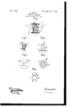
- Figure l shows a longitudinal section through the two parts, which are shown connected with one another in the position they occupy during use.
- Figs. 2 and 3 show, respectively, in side elevation and plan, that part of the fastener which is pinned through the material of the article of clothing or the likein question.
- Figs. 4 and 5 show, respectively, in side elevation and plan, that part of the fastener which serves as a socket for the reception of the other part.
- Fig. 6 shows, by way of example, another form in which the part shown in Figs. 2 and 3 maybe manufactured.
- the head or pin portion (represented in Figs. 2, 3, and 6) is formed bymeans of aplate which is turned over.
- the base or socket portion (represented separately in Figs. 4 and 5) consists of a plate a, with which the (at e somewhat outwardly bent) hollow cylinder or socket e is rigidly connected.
- the plate 0 carries at its middle the shank or stem (1,
- the pins 6 are stuck through the material in question or through the portions f g of material which are to be held together, after which the other portion or socket of the fastener, the parts of which are designated by c d e, is pressed on.
- k represents the section of a buttonhole or loop placed over the neck of the portion illustrated in Figs. 4 and 5.
- the fastener according as it is to be employed for connecting two pieces of material or for fastening a buttonhole or loop is made shorter or longer.
- a fastening device of the character described consisting of a head portion, comprising a plate and a plurality of resilient pins arranged in a circle and secured to said plate, each of said pins having an inward kneesha ed bend, and a base portion, comprising a p ate, a socket attached to the same, and a central shank arranged in said socket and having a head, the bends of the pins being adapted to engage behind said shank-head when the head portion is in engagement with the base portion.
- a fastening device of the character described consisting of' a head portion, comprising a plate, a plurality of resilient pins arranged in a circle and riveted to said plate, each of said pins having an inward kneeshaped bend, and a plate secured to the former plate and covering over the riveted ends of said pins, and a base portion, comprising a plate, a socket attached to the name to this specification in the presence of same, and a central shank arranged in said two subscribing Witnesses.
Landscapes
- Slide Fasteners, Snap Fasteners, And Hook Fasteners (AREA)
Description
No. 809,351. PATBNTBD JAN. 9, 1906. E. WUTZEL.
FA$TBNING DEVICE.
APPLIGATION FILED MAY 24, 1905.
Fig.1.
EMIL -WOTZEL, OF V ZWIOKAU, GERMANY.
FASTENING DEVICE.-
Specification of Letters Patent.
Patented Jan. 9, 1906.
Application filed May 24, 1905. Serial No. 262,052.
To all whom it WAG/y concern:
Be it known that I, EMIL WoTzEL, a subj ect of the German Emperor, and a resident of Zwickau, Germany, have invented a new and useful Improved Fastening Device, of
which the following is a specification.
ing devices.
In the accompanying drawings, which illustrate a fastener according to the present invention, Figure l shows a longitudinal section through the two parts, which are shown connected with one another in the position they occupy during use. Figs. 2 and 3 show, respectively, in side elevation and plan, that part of the fastener which is pinned through the material of the article of clothing or the likein question. Figs. 4 and 5 show, respectively, in side elevation and plan, that part of the fastener which serves as a socket for the reception of the other part. Fig. 6 shows, by way of example, another form in which the part shown in Figs. 2 and 3 maybe manufactured.
The head or pin portion (represented in Figs. 2, 3, and 6) is formed bymeans of aplate which is turned over.
a, upon which the resilient pins or needles 6, arranged in a circle and formed with similar inward bends b, are arranged in any de sired manner. In the case of the form of construction according to Figs. 1, 2, and 3 the pins are riveted on and the connection is covered over by means of a plate the edge of In the case of the form of construction according to Fig. 6 the plate and the pins are stamped out of one piece. The base or socket portion (represented separately in Figs. 4 and 5) consists of a plate a, with which the (at e somewhat outwardly bent) hollow cylinder or socket e is rigidly connected. Moreover, the plate 0 carries at its middle the shank or stem (1,
which is provided with a roll-shaped or bulb shaped thickened head. If now the socket e be pushed over the pins 1), the shank cl enters between the latter, and thereby forces the resilient bends b outward, whereupon the latter are again forced together behind the head (1 of the shank d, and thus render the engagement secure. On account of the form' of the shank-head d and the socket e, inclosing the pins 1), an opening of the fastener or button-pin by a lateral pull or pressure is rendered impossible. On the contrary, the connection of the two parts of the fastener can by means of a suitably-strong axial pull be unfastened without a previous release of special connecting devices being necessary.
On using the fastener the pins 6 are stuck through the material in question or through the portions f g of material which are to be held together, after which the other portion or socket of the fastener, the parts of which are designated by c d e, is pressed on.
k represents the section of a buttonhole or loop placed over the neck of the portion illustrated in Figs. 4 and 5.
The fastener according as it is to be employed for connecting two pieces of material or for fastening a buttonhole or loop is made shorter or longer.
What I claim as my invention, and desire to secure by Letters Patent, is
1. A fastening device of the character described, consisting of a head portion, comprising a plate and a plurality of resilient pins arranged in a circle and secured to said plate, each of said pins having an inward kneesha ed bend, and a base portion, comprising a p ate, a socket attached to the same, and a central shank arranged in said socket and having a head, the bends of the pins being adapted to engage behind said shank-head when the head portion is in engagement with the base portion.
2. A fastening device of the character described, consisting of' a head portion, comprising a plate, a plurality of resilient pins arranged in a circle and riveted to said plate, each of said pins having an inward kneeshaped bend, and a plate secured to the former plate and covering over the riveted ends of said pins, and a base portion, comprising a plate, a socket attached to the name to this specification in the presence of same, and a central shank arranged in said two subscribing Witnesses.
socket and having a head, the bends of the pins being adapted to engage behind said EMIL WOTZEL' 5 shank-head when the head portion is in en- Witnesses:
gagement with the base portion. WOLDEMAR HAUPT,
In testimony whereof I have signed my HENRY I-IAsPER.
Priority Applications (1)
| Application Number | Priority Date | Filing Date | Title |
|---|---|---|---|
| US26205205A US809351A (en) | 1905-05-24 | 1905-05-24 | Fastening device. |
Applications Claiming Priority (1)
| Application Number | Priority Date | Filing Date | Title |
|---|---|---|---|
| US26205205A US809351A (en) | 1905-05-24 | 1905-05-24 | Fastening device. |
Publications (1)
| Publication Number | Publication Date |
|---|---|
| US809351A true US809351A (en) | 1906-01-09 |
Family
ID=2877832
Family Applications (1)
| Application Number | Title | Priority Date | Filing Date |
|---|---|---|---|
| US26205205A Expired - Lifetime US809351A (en) | 1905-05-24 | 1905-05-24 | Fastening device. |
Country Status (1)
| Country | Link |
|---|---|
| US (1) | US809351A (en) |
Cited By (3)
| Publication number | Priority date | Publication date | Assignee | Title |
|---|---|---|---|---|
| US2903766A (en) * | 1956-10-04 | 1959-09-15 | Spyros M Fotiades | Clasp, binder and key |
| US4176428A (en) * | 1977-02-05 | 1979-12-04 | Nifco, Inc. | Panel fastener |
| US6412153B1 (en) * | 2000-08-23 | 2002-07-02 | International Business Machines Corporation | Device for attaching at least two pieces of material |
-
1905
- 1905-05-24 US US26205205A patent/US809351A/en not_active Expired - Lifetime
Cited By (3)
| Publication number | Priority date | Publication date | Assignee | Title |
|---|---|---|---|---|
| US2903766A (en) * | 1956-10-04 | 1959-09-15 | Spyros M Fotiades | Clasp, binder and key |
| US4176428A (en) * | 1977-02-05 | 1979-12-04 | Nifco, Inc. | Panel fastener |
| US6412153B1 (en) * | 2000-08-23 | 2002-07-02 | International Business Machines Corporation | Device for attaching at least two pieces of material |
Similar Documents
| Publication | Publication Date | Title |
|---|---|---|
| US809351A (en) | Fastening device. | |
| US573059A (en) | Garment-fastener | |
| US1017865A (en) | Cuff-fastener. | |
| US811661A (en) | Detachable fastener and button. | |
| US1301855A (en) | Garment-fastener. | |
| US334349A (en) | Button or stud | |
| US718018A (en) | Placket-holder. | |
| US507927A (en) | Carl august pfenning | |
| US1228212A (en) | Cuff-button. | |
| US847291A (en) | Separable fastening. | |
| US300028A (en) | Clinton stephens | |
| US1297345A (en) | Button. | |
| US269756A (en) | Button | |
| US715520A (en) | Fastening device. | |
| US845473A (en) | Separable fastener. | |
| US479884A (en) | Bernhard kersting | |
| US1185599A (en) | Collar-fastener. | |
| US444234A (en) | Sylvania | |
| US1019324A (en) | Combined tie and collar fastener. | |
| US385239A (en) | Teeeitoey | |
| US1083139A (en) | Fastener. | |
| US484669A (en) | Cuff button and fastener | |
| US335226A (en) | jefferys | |
| US476540A (en) | Thirds to philip b | |
| US581224A (en) | Fastening device |