US809246A - Pantograph. - Google Patents
Pantograph. Download PDFInfo
- Publication number
- US809246A US809246A US26879805A US1905268798A US809246A US 809246 A US809246 A US 809246A US 26879805 A US26879805 A US 26879805A US 1905268798 A US1905268798 A US 1905268798A US 809246 A US809246 A US 809246A
- Authority
- US
- United States
- Prior art keywords
- point
- holder
- tracing
- board
- pencil
- Prior art date
- Legal status (The legal status is an assumption and is not a legal conclusion. Google has not performed a legal analysis and makes no representation as to the accuracy of the status listed.)
- Expired - Lifetime
Links
Images
Classifications
-
- B—PERFORMING OPERATIONS; TRANSPORTING
- B44—DECORATIVE ARTS
- B44B—MACHINES, APPARATUS OR TOOLS FOR ARTISTIC WORK, e.g. FOR SCULPTURING, GUILLOCHING, CARVING, BRANDING, INLAYING
- B44B3/00—Artists' machines or apparatus equipped with tools or work holders moving or able to be controlled substantially two-dimensionally for carving, engraving, or guilloching shallow ornamenting or markings
- B44B3/001—Artists' machines or apparatus equipped with tools or work holders moving or able to be controlled substantially two-dimensionally for carving, engraving, or guilloching shallow ornamenting or markings by copying
- B44B3/002—Artists' machines or apparatus equipped with tools or work holders moving or able to be controlled substantially two-dimensionally for carving, engraving, or guilloching shallow ornamenting or markings by copying using a pantograph
Definitions
- My invention has relation to pantographs
- the principal objects of my invention are, first, to provide a pantograph with a curved revolving tracing-point to permit of the eX- act reproduction of curved objects, especially the tread portions of rails, by drawing to show wear of same or irregularities therein due to poor material or faulty construction;
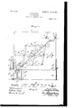
- FIG. 1 is a view, partly in section and partly in side elevation, of apantograph, illustrating the manner of clamping the same to a rail, the profile of which is to be reproduced by a drawing embodying main features of my Fig. 2 is a detail view illustrating perspectively a standarding or alining bar.
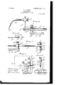
- Figs. 3 and 4 are detail views, enlarged, illustrating, respectively, in section and in elevation the revolving tracing-point and adjustable pencil-holder and their respective connections with a telescoping holder and a portion of the pantographlimbs carrying the same.
- Fig. 1 is a view, partly in section and partly in side elevation, of apantograph, illustrating the manner of clamping the same to a rail, the profile of which is to be reproduced by a drawing embodying main features of my Fig. 2 is a detail view illustrating perspectively a standarding or alining bar.
- Figs. 3 and 4 are detail views, enlarged, illustrating, respectively, in
- FIG. 5 is a detail view illustrating in elevation means for clamping the pencil-holder to its telescoping support.
- Fig. 6 is a detail view illustrating in end elevation the pencil-holder and its support; and
- Fig. 7 is a detail view illustrating, partly in section and partly in rear elevation, the clamp for connecting the pantograph with a rail.
- a is a board or plate, to which, by means of bolts 0, and thumb-nuts a is removably secured the member I) of a clamp 11, the other member 6 of which is pivotally connected in the point 6 to a lug b of the member I).
- Both members I) and b of the clamp b are provided at their free ends with gripping-jaws b adapted to engage the foot 0 of a rail 0 from opposite sides and to clamp the board a to the same.
- the member 6 thereof is adjustably connected with the member I) by a threaded bolt 5 se cured to a lug b of the member I), and by a thumb-nut b engaging the bolt N, which nut by bearing against the member 6 forces the same toward the member b, and thus permits of the engagement of the foot portions 0 of rails of varying sizes by the members I) and b
- the board a by means of the clamp b may be thus readily connected to and disconnected from the rail 0 and held by the clamp 11 in proper position with respect to the same.
- a rod d slidably arranged in a bracket d, secured to the board a, assists in the support of the board on the rail 0, and a set-screw (Z of the bracket (1, engaging the rod (1, serves to clamp the rod to the bracket d when the same assumes its proper position with respect to the board 0,, as will-be readily understood in connection with Fig. 1 of the drawings.
- the frame e of the pantograph consisting of three horizontally andthree transversely disposed limbs e, e, and e and 6 e, and 6 respectively, which are joined to gether at their ends and at a point intermediate thereto, forming the frame 7, which may be turned on its pivotal point e and the limbs of which may assume various angular positions with respect to each other when one of its corners is moved toward or away from the pivotal point e", which remains fixed on the board a.
- the fixed pivotal point e for the frame 0 as well as the movable pivotal points e and e for the limbs e and e and e and e are formed by the extensions of the bearings 6 e, and a adapted to receive and support a telescoping holder f, consisting of a tube f and a rod f sliding in the tube f and to hold the same normally in a diagonal position with respect to the frame 6 as shown in Fig. 1.
- a rod f forming a bearing for a sleeve f held in position thereon by a clamping-screw
- sleeve f 4 is provided with a laterally-extending arm f, forming the su port for a curved finger or tracingpoint, which is adjustably clamped to the armf by means of a set-screwf.
- the free end 6 of the curved tracing-point e is held in the central longitudinal axis of the tube f and rod f by means of the arm f and when out of this po sition may be easily returned to the same by sliding the point on the arm f.
- a pencil-holder g consisting of a sleeve 9, to a certain extent concentrically adjustable with respect to the rodf by means of a set-screw g, passing through a slot 9 of the sleeve g, as shown in Fig. 5.
- the sleeve 9 is slotted so as to form a yielding tongue 9 which by means of a set-screw 9 permits of the clamping of the same to the rod f as shown in Fig. 4.
- the sleeve 9 is provided with a tubular extension 9 forming a housing for a pencil g, which, by means of a threaded bolt g passing through an angular slot 9 is removably connected with the housing.
- a tubular extension 9 forming a housing for a pencil g, which, by means of a threaded bolt g passing through an angular slot 9 is removably connected with the housing.
- a spring 9, arranged in the housing g tends to hold the pencil g in engagement with the paper h and permits the same to freely slide over uneven portions of the same without breaking the point g thereof.
- the bearing 0 for the rod f 2 is clamped to the same by a set-screw e in the same manner as the bearing a for the tube f of the holder f, which is clamped thereto by a set-screw e, as shown in Figs. 3 and 4.
- the rod f is forced to slide within the tubef when the frame 6 by engaging the tracing-pointf is moved.
- the tracing-point f In order to ascertain the extent of wear of the tread c of the head a of the rail 0 or of irregularities in the same, the tracing-point f, with its free end f is brought into contact with the head 0 of the rail and moved over the surface of the same. Owing to the curvature of the traoing-point and its ability to turn on the rod f 3 of the tube f, which forms its axle, the same may be easily moved over the horizontally-disposed tread portion a of the head 0 and over the vertically and obliquely disposed sides thereof, and this movement may be continued to the web portion of the rail 0, if desired.
- a standardizing bar or aliner 7c This bar consists of a flat strip of metal through which a bolt, (not shown,) forming the pivotal point e for the frame 6 passes to center the bar In with respect to the holder f and which by means of screws 7c is connected with the board a, as shown in Fig. 1.
- the bar 7c is provided with a post Z, the central longitudinal axis of which is marked by the depression 1, arranged in the free end of the post, and at its other end the bar is provided with similar depressions l indicating the central longitudinal axis of the bar k at this end, as shown in Fig. 2.
- the depressions of the post and bar are an equal distance apart from the pivotal point e of the frame 6 as shown in Fig.
- the tracing-pointf can be laterally adjusted with respect to the holder f by sliding the same on the arm f as will be readily understood from Fig. 3 of the drawings.
- a pantograph a movable frame, a holder, consisting of members slidable in each other and having a tracing-point and drawing means arranged at their respective free ends, said tracing-point being curved and pivotally secured to said holder and its free end arranged in the longitudinal central axis thereof to remain in alinement therewith during turning of said tracing-point around its holder and said tracing-point adapted to permit of the reproduction of its movements by said drawing means by expanding and contracting said holder by said frame.
- a pantograph a movable frame, a holder, consisting of members slidable in each other and having a tracing-point and drawing means carried by said holder, said tracing-point curved and pivotally secured to said holder and its free end arranged in the longitudinal central axis to ermit said tracing-point by turning on said older to be moved over curved objects and to remain with its end in the longitudinal central axis of said holder and said tracing-point adapted to permit of the reproduction of its movements by said drawing means by the expanding and contracting of said holder by said frame.
- a movable frame consisting of two members slidable in each other and having a tracing-point and a pencil carried by said holder at opposite ends, said tracing-point curved and pivotally secured to said holder and its free end arranged in the longitudinal central axis thereof to permit said tracing-point by turning on said older to be moved over curved objects, and said pencil being adapted to be actuated by the movementsof said tracing-point and by the sliding of said holder members within each other to reproduce a profile of the object.
- a frame consisting of a series of limbs movably joined to each other at their respective ends and a point intermediate thereof, a telescoping holder carried and actuated by saidframe e, an arm pivotally secured to one end of said holder, a curved tracing-point slidably arranged on said arm and having an end arranged in the central longitudinal axis of said holder, and a pencil-holder arranged at the other end of said holder and having a pencil movably arranged therein.
- a board a movable frame pivotally secured to said board, a holder having a tracing-point and a pencil carried by said frame, a clamp arranged at one side of said board and adapted to engage an object to be traced by said tracing-point and to be reproduced in profile by said pencil, and adjustable means arranged at the opposite side of said board, said means and clamp adapted to hold said board and frame in proper position with respect to said object.
- a pantograph a board, a movable frame pivotally secured to said board, a holder having a tracing-point and a pencil carried by said frame, a clamp consisting of two members pivotally connected with each other and having gripping-jaws adapted to engage the object to be traced by said tracing-point and to be reproduced in profile by said pencil and'to hold said board and frame in proper position thereto, and means adapted to hold the members of said clamp in engagement with the object.
- a board In a pantograph, a board, a movable frame pivotally secured to said board, a holder carried by said frame and having at opposite ends a tracing-point and a pencil prrojecting from said holder beyond said ame, and a standardizing bar or aliner carried by said board having a post and markings arranged at opposite ends thereon, said markings and post adapted, when said pencil and tracing-points are respectively brought into alinement with the same to facilitate an adjustment of the tracing-point and pencil on said holder.
- a board a frame consisting of a series of limbs movably oined to each other at their respective ends and at points intermediate thereto movably connected with said board, a holder, consisting of a tube and a rod movably secured to said frame, a tracing-point and pencil movably and adjustably secured to said tube and rod, and a clamp adapted to connect said board with the object to be drawn.
- a board a frame consisting of a series of limbs movably joined to each other'at their respective ends and at points intermediate thereto movably connected with said board, a holder, consisting of a tube and a rod movably secured to said frame, a tracing-point and pencil respectively movably and adjustably secured to said tube and rod,'a clamp adapted to connect said board with the object to be drawn, and a standardizing bar or aliner carried by said board and arranged below said frame and having a post and markings arranged atopposite ends thereon and adapted to serve as a guide to bring said tracing-point and pencil back to their respective relative positions when away from the same.
- a pantograph a board, a movable frame pivotally secured to said board, a
Landscapes
- Mechanical Pencils And Projecting And Retracting Systems Therefor, And Multi-System Writing Instruments (AREA)
Description
No. 809,246. PATENTED JAN. 2, 1906.
N. H. BROWN.
PANTOGRAPH.
APPLIOATION FILED JULY 8, 1905.
2 SHEETS-SHEET 1.
No. 809,246. Q PATENTED JAN. 2, 1906. N. H. BROWN.
PANTOGRAPH.
APPLIOATION FILED JULY 8, 1905.
2 SHEETS SHEET 2.
said invention.
UNITED STATES PATENT OFFICE.
NATHANIEL H. BROWN, OF PHILADELPHIA, PENNSYLVANIA, ASSIGNOR TO WILLIAMS, BROWN & EARLE, OF PHILADELPHIA, PENNSYLVANIA.
PANTOGRAPH.
Specification of Letters Patent.
, Patented Jan. 2, 1906.
following is a specification.
My invention has relation to pantographs,
and in such connection it relates more particularly to that class of pantographs adapted to reproduce profiles of curvedobjects.
The principal objects of my invention are, first, to provide a pantograph with a curved revolving tracing-point to permit of the eX- act reproduction of curved objects, especially the tread portions of rails, by drawing to show wear of same or irregularities therein due to poor material or faulty construction;
second, to provide a pantogra h with means to permit of the adjustment 0 the curved revolving tracing point to compensate for wear of the same and to hold the end contacting with the object to be traced in the central longitudinal axis of its holder; third, to provide a pantograph with an adjustable pencil-holder to permit of a lifting of the same during adjustment and when not in use; fourth, to provide a pantograph with a standardizing bar or aliner to permit of the adjustment of the revolving tracing-point and pencil with respect to one another, and, fifth, to provide a pantograph with an ad justable clamp adapted to permit of the clamping of the pantograph to various-sized rails and holding of the same in proper position with respect to the rails.
The nature and scope of my invention will be more fully understood from the following description, taken in connection with the accompanying drawings, forming part hereof, in which Figure 1 is a view, partly in section and partly in side elevation, of apantograph, illustrating the manner of clamping the same to a rail, the profile of which is to be reproduced by a drawing embodying main features of my Fig. 2 is a detail view illustrating perspectively a standarding or alining bar. Figs. 3 and 4 are detail views, enlarged, illustrating, respectively, in section and in elevation the revolving tracing-point and adjustable pencil-holder and their respective connections with a telescoping holder and a portion of the pantographlimbs carrying the same. Fig. 5 is a detail view illustrating in elevation means for clamping the pencil-holder to its telescoping support. Fig. 6 is a detail view illustrating in end elevation the pencil-holder and its support; and Fig. 7 is a detail view illustrating, partly in section and partly in rear elevation, the clamp for connecting the pantograph with a rail.
Referring to the drawings, a is a board or plate, to which, by means of bolts 0, and thumb-nuts a is removably secured the member I) of a clamp 11, the other member 6 of which is pivotally connected in the point 6 to a lug b of the member I). Both members I) and b of the clamp b are provided at their free ends with gripping-jaws b adapted to engage the foot 0 of a rail 0 from opposite sides and to clamp the board a to the same. In order to permit of the ready engagement of the clamp b to the rail 0, the member 6 thereof is adjustably connected with the member I) by a threaded bolt 5 se cured to a lug b of the member I), and by a thumb-nut b engaging the bolt N, which nut by bearing against the member 6 forces the same toward the member b, and thus permits of the engagement of the foot portions 0 of rails of varying sizes by the members I) and b As shown in Figs. 1 and 2, the board a by means of the clamp b may be thus readily connected to and disconnected from the rail 0 and held by the clamp 11 in proper position with respect to the same. A rod d, slidably arranged in a bracket d, secured to the board a, assists in the support of the board on the rail 0, and a set-screw (Z of the bracket (1, engaging the rod (1, serves to clamp the rod to the bracket d when the same assumes its proper position with respect to the board 0,, as will-be readily understood in connection with Fig. 1 of the drawings.
To the board a, forming a part of the pantograph, and in the point e is pivotally secured the frame e of the pantograph, consisting of three horizontally andthree transversely disposed limbs e, e, and e and 6 e, and 6 respectively, which are joined to gether at their ends and at a point intermediate thereto, forming the frame 7, which may be turned on its pivotal point e and the limbs of which may assume various angular positions with respect to each other when one of its corners is moved toward or away from the pivotal point e", which remains fixed on the board a. The fixed pivotal point e for the frame 0 as well as the movable pivotal points e and e for the limbs e and e and e and e are formed by the extensions of the bearings 6 e, and a adapted to receive and support a telescoping holder f, consisting of a tube f and a rod f sliding in the tube f and to hold the same normally in a diagonal position with respect to the frame 6 as shown in Fig. 1. To the tube f is preferably brazed a rod f forming a bearing for a sleeve f held in position thereon by a clamping-screw), which sleeve f 4 is provided with a laterally-extending arm f, forming the su port for a curved finger or tracingpoint, which is adjustably clamped to the armf by means of a set-screwf. As shown in Figs. 1 and 3, the free end 6 of the curved tracing-point e is held in the central longitudinal axis of the tube f and rod f by means of the arm f and when out of this po sition may be easily returned to the same by sliding the point on the arm f. Opposite the tracing-point e the rod f sliding within the tube f is provided at its free end with a pencil-holder g, consisting of a sleeve 9, to a certain extent concentrically adjustable with respect to the rodf by means of a set-screw g, passing through a slot 9 of the sleeve g, as shown in Fig. 5. The sleeve 9 is slotted so as to form a yielding tongue 9 which by means of a set-screw 9 permits of the clamping of the same to the rod f as shown in Fig. 4. The sleeve 9 is provided with a tubular extension 9 forming a housing for a pencil g, which, by means of a threaded bolt g passing through an angular slot 9 is removably connected with the housing. By raising the pencil g in the slot 9 and turning the same into the right-angular extension g thereof the pencil-point 9 may be lifted from the paper h, placed on the board a, and held out of engagement therewith or with the board itself when not in use. A spring 9, arranged in the housing g tends to hold the pencil g in engagement with the paper h and permits the same to freely slide over uneven portions of the same without breaking the point g thereof. The bearing 0 for the rod f 2 is clamped to the same by a set-screw e in the same manner as the bearing a for the tube f of the holder f, which is clamped thereto by a set-screw e, as shown in Figs. 3 and 4. By this arrangement the rod f is forced to slide within the tubef when the frame 6 by engaging the tracing-pointf is moved.
In order to ascertain the extent of wear of the tread c of the head a of the rail 0 or of irregularities in the same, the tracing-point f, with its free end f is brought into contact with the head 0 of the rail and moved over the surface of the same. Owing to the curvature of the traoing-point and its ability to turn on the rod f 3 of the tube f, which forms its axle, the same may be easily moved over the horizontally-disposed tread portion a of the head 0 and over the vertically and obliquely disposed sides thereof, and this movement may be continued to the web portion of the rail 0, if desired. During this movement of the tracing-point f the pencilpoint g held in contact with the paper h, removably secured to the board a by means of clamps i, draws the exact reproduction of the outline of the head and tread portion of the rail 0 onto the paper h, as shown in Fig.
1, and hence permit of readily determining the extent of wear of the tread and inner sides of the rail 0. At the same time any irregularities in the surface of the rail and of the extent of the same can be accurately and quickly drawn on the paper h.
In order to compensate for wear of the end f 8 of the tracing-pointf7, due to sliding of the same over the rail 0, and of the pencilpoint 9 by drawing the outline of the rail on the paper ft or in case the pencil and the tracingpoints have been moved out of their respective relative positions through other causes, there is arranged under the frame 6 a standardizing bar or aliner 7c. This bar consists of a flat strip of metal through which a bolt, (not shown,) forming the pivotal point e for the frame 6 passes to center the bar In with respect to the holder f and which by means of screws 7c is connected with the board a, as shown in Fig. 1. At one end the bar 7c is provided with a post Z, the central longitudinal axis of which is marked by the depression 1, arranged in the free end of the post, and at its other end the bar is provided with similar depressions l indicating the central longitudinal axis of the bar k at this end, as shown in Fig. 2. The depressions of the post and bar are an equal distance apart from the pivotal point e of the frame 6 as shown in Fig. 1, and in order to ascertain whether the tracing-pointf and the point 9 of thepencil g are in their proper relative positions the holder f is swung into alinement with the bar is, and by this movement the tracing point f is brought into engagement with the intersection of the depressions Z of the postZ and the pencil-point 9 into engagement with the intersection of the depressions P. If it is found that these points do not occupy a position directly opposite the depressions Z and Z the set-screws e and e of the holder f are loosened, and the tube f and rod f 2 are adjusted until the points f 8 and g are brought opposite the depressions Z and Z Owing to the wear of the end f S of the tracing-point the same will be held above the post Z of the alining bar is instead of contacting with the same.
By-the loosening of the set-screw f however, the tracing-pointf can be laterally adjusted with respect to the holder f by sliding the same on the arm f as will be readily understood from Fig. 3 of the drawings.
Having thus described the nature and objects of my invention, what I claim as new, and desire to secure by Letters Patent, is
1. In a pantograph, a movable frame, a holder, consisting of members slidable in each other and having a tracing-point and drawing means arranged at their respective free ends, said tracing-point being curved and pivotally secured to said holder and its free end arranged in the longitudinal central axis thereof to remain in alinement therewith during turning of said tracing-point around its holder and said tracing-point adapted to permit of the reproduction of its movements by said drawing means by expanding and contracting said holder by said frame.
2. In a pantograph, a movable frame, a holder, consisting of members slidable in each other and having a tracing-point and drawing means carried by said holder, said tracing-point curved and pivotally secured to said holder and its free end arranged in the longitudinal central axis to ermit said tracing-point by turning on said older to be moved over curved objects and to remain with its end in the longitudinal central axis of said holder and said tracing-point adapted to permit of the reproduction of its movements by said drawing means by the expanding and contracting of said holder by said frame.
3. In a pantograph, a movable frame, a holder, consisting of two members slidable in each other and having a tracing-point and a pencil carried by said holder at opposite ends, said tracing-point curved and pivotally secured to said holder and its free end arranged in the longitudinal central axis thereof to permit said tracing-point by turning on said older to be moved over curved objects, and said pencil being adapted to be actuated by the movementsof said tracing-point and by the sliding of said holder members within each other to reproduce a profile of the object.
4.. In a pantograph, a frame consisting of a series of limbs movably joined to each other at their respective ends and a point intermediate thereof, a telescoping holder carried and actuated by saidframe e, an arm pivotally secured to one end of said holder, a curved tracing-point slidably arranged on said arm and having an end arranged in the central longitudinal axis of said holder, and a pencil-holder arranged at the other end of said holder and having a pencil movably arranged therein.
5. In a pantograph, a board, a movable frame pivotally secured to said board, a holder having a tracing-point and a pencil carried by said frame, a clamp arranged at one side of said board and adapted to engage an object to be traced by said tracing-point and to be reproduced in profile by said pencil, and adjustable means arranged at the opposite side of said board, said means and clamp adapted to hold said board and frame in proper position with respect to said object.
6. In a pantograph, a board, a movable frame pivotally secured to said board, a holder having a tracing-point and a pencil carried by said frame, a clamp consisting of two members pivotally connected with each other and having gripping-jaws adapted to engage the object to be traced by said tracing-point and to be reproduced in profile by said pencil and'to hold said board and frame in proper position thereto, and means adapted to hold the members of said clamp in engagement with the object.
7. In a pantograph, a board, a movable frame pivotally secured to said board, a holder carried by said frame and having at opposite ends a tracing-point and a pencil prrojecting from said holder beyond said ame, and a standardizing bar or aliner carried by said board having a post and markings arranged at opposite ends thereon, said markings and post adapted, when said pencil and tracing-points are respectively brought into alinement with the same to facilitate an adjustment of the tracing-point and pencil on said holder.
8. In a pantograph, a board, a frame consisting of a series of limbs movably oined to each other at their respective ends and at points intermediate thereto movably connected with said board, a holder, consisting of a tube and a rod movably secured to said frame, a tracing-point and pencil movably and adjustably secured to said tube and rod, and a clamp adapted to connect said board with the object to be drawn.
9. In a pantograph, a board, a frame consisting of a series of limbs movably joined to each other'at their respective ends and at points intermediate thereto movably connected with said board, a holder, consisting of a tube and a rod movably secured to said frame, a tracing-point and pencil respectively movably and adjustably secured to said tube and rod,'a clamp adapted to connect said board with the object to be drawn, and a standardizing bar or aliner carried by said board and arranged below said frame and having a post and markings arranged atopposite ends thereon and adapted to serve as a guide to bring said tracing-point and pencil back to their respective relative positions when away from the same.
10. In a pantograph, a board, a movable frame pivotally secured to said board, a
I holder for a traci11g-point and pencil carried In testimony whereof I have hereunto set my signature 1n the presence of tWo subscrlb- IO ing Witnesses.
NATHANIEL H. BROWN.
Witnesses J. WALTER DoUGLAss, THOMAS M. SMITH.
Priority Applications (1)
| Application Number | Priority Date | Filing Date | Title |
|---|---|---|---|
| US26879805A US809246A (en) | 1905-07-08 | 1905-07-08 | Pantograph. |
Applications Claiming Priority (1)
| Application Number | Priority Date | Filing Date | Title |
|---|---|---|---|
| US26879805A US809246A (en) | 1905-07-08 | 1905-07-08 | Pantograph. |
Publications (1)
| Publication Number | Publication Date |
|---|---|
| US809246A true US809246A (en) | 1906-01-02 |
Family
ID=2877727
Family Applications (1)
| Application Number | Title | Priority Date | Filing Date |
|---|---|---|---|
| US26879805A Expired - Lifetime US809246A (en) | 1905-07-08 | 1905-07-08 | Pantograph. |
Country Status (1)
| Country | Link |
|---|---|
| US (1) | US809246A (en) |
Cited By (1)
| Publication number | Priority date | Publication date | Assignee | Title |
|---|---|---|---|---|
| US2782505A (en) * | 1955-06-03 | 1957-02-26 | Guischard Charles Henry | Pantograph |
-
1905
- 1905-07-08 US US26879805A patent/US809246A/en not_active Expired - Lifetime
Cited By (1)
| Publication number | Priority date | Publication date | Assignee | Title |
|---|---|---|---|---|
| US2782505A (en) * | 1955-06-03 | 1957-02-26 | Guischard Charles Henry | Pantograph |
Similar Documents
| Publication | Publication Date | Title |
|---|---|---|
| US809246A (en) | Pantograph. | |
| US1149120A (en) | Drawing-machine. | |
| US2312154A (en) | Drafting apparatus | |
| US1039901A (en) | Combined calipers and protractor. | |
| US1482606A (en) | Drafting instrument | |
| US795065A (en) | Drafting-table. | |
| US1014803A (en) | Drafting instrument. | |
| US880796A (en) | Drafting instrument. | |
| US943886A (en) | Drafting and engraving machine. | |
| US2559280A (en) | Center and eccentric point marker | |
| US2671965A (en) | Device for projecting drawings | |
| US985070A (en) | Skirt-marker. | |
| US688061A (en) | Parallel-ruler. | |
| CN220136263U (en) | Stone material cutting back surface detection device | |
| US1422345A (en) | Trammel | |
| US2583219A (en) | Air-pressure operated drawer clamping machine | |
| US784633A (en) | Duplicating defect-tracer. | |
| US506761A (en) | Conformator | |
| US1131379A (en) | Engraving-machine. | |
| US678650A (en) | Ruler. | |
| US2316483A (en) | Contour scriber | |
| US3000098A (en) | Contour marker adapter | |
| US2823456A (en) | Pantograph | |
| US514992A (en) | Pantograph | |
| US521597A (en) | Draftsman s rule |