US8092211B2 - Vertical type injection molding machine - Google Patents
Vertical type injection molding machine Download PDFInfo
- Publication number
- US8092211B2 US8092211B2 US12/643,368 US64336809A US8092211B2 US 8092211 B2 US8092211 B2 US 8092211B2 US 64336809 A US64336809 A US 64336809A US 8092211 B2 US8092211 B2 US 8092211B2
- Authority
- US
- United States
- Prior art keywords
- movable body
- mold
- weight
- movable
- weights
- Prior art date
- Legal status (The legal status is an assumption and is not a legal conclusion. Google has not performed a legal analysis and makes no representation as to the accuracy of the status listed.)
- Expired - Fee Related, expires
Links
- 238000001746 injection moulding Methods 0.000 title claims abstract description 45
- 230000007246 mechanism Effects 0.000 claims abstract description 33
- 239000011347 resin Substances 0.000 description 10
- 229920005989 resin Polymers 0.000 description 10
- 239000003921 oil Substances 0.000 description 9
- 239000011796 hollow space material Substances 0.000 description 6
- 238000002347 injection Methods 0.000 description 4
- 239000007924 injection Substances 0.000 description 4
- 238000009434 installation Methods 0.000 description 4
- 230000002787 reinforcement Effects 0.000 description 3
- 230000005484 gravity Effects 0.000 description 2
- 239000010720 hydraulic oil Substances 0.000 description 2
- SUDBRAWXUGTELR-HPFNVAMJSA-N 5-[[(2r,3r,4s,5s,6r)-3,4,5-trihydroxy-6-(hydroxymethyl)oxan-2-yl]oxymethyl]-1h-pyrimidine-2,4-dione Chemical compound O[C@@H]1[C@@H](O)[C@H](O)[C@@H](CO)O[C@H]1OCC1=CNC(=O)NC1=O SUDBRAWXUGTELR-HPFNVAMJSA-N 0.000 description 1
- 238000001816 cooling Methods 0.000 description 1
- 239000002184 metal Substances 0.000 description 1
- 238000000465 moulding Methods 0.000 description 1
- 230000000630 rising effect Effects 0.000 description 1
- 238000000926 separation method Methods 0.000 description 1
Images


Classifications
-
- B—PERFORMING OPERATIONS; TRANSPORTING
- B29—WORKING OF PLASTICS; WORKING OF SUBSTANCES IN A PLASTIC STATE IN GENERAL
- B29C—SHAPING OR JOINING OF PLASTICS; SHAPING OF MATERIAL IN A PLASTIC STATE, NOT OTHERWISE PROVIDED FOR; AFTER-TREATMENT OF THE SHAPED PRODUCTS, e.g. REPAIRING
- B29C45/00—Injection moulding, i.e. forcing the required volume of moulding material through a nozzle into a closed mould; Apparatus therefor
- B29C45/17—Component parts, details or accessories; Auxiliary operations
- B29C45/64—Mould opening, closing or clamping devices
-
- B—PERFORMING OPERATIONS; TRANSPORTING
- B29—WORKING OF PLASTICS; WORKING OF SUBSTANCES IN A PLASTIC STATE IN GENERAL
- B29C—SHAPING OR JOINING OF PLASTICS; SHAPING OF MATERIAL IN A PLASTIC STATE, NOT OTHERWISE PROVIDED FOR; AFTER-TREATMENT OF THE SHAPED PRODUCTS, e.g. REPAIRING
- B29C45/00—Injection moulding, i.e. forcing the required volume of moulding material through a nozzle into a closed mould; Apparatus therefor
- B29C45/17—Component parts, details or accessories; Auxiliary operations
Definitions
- the present invention relates to a vertical type injection molding machine that reduces the load on a motor that drives a movable mold.
- Conventional injection molding machines include horizontal types in which clamping is performed along the installation surface, or along the horizontal direction and vertical types in which clamping is performed along the vertical direction. Since the movable mold of a horizontal type injection molding machine is moved horizontally, the movable mold is hardly influenced by the gravity unlike the movable mold in a vertical type injection molding, which is moved vertically. Thus, in a horizontal type injection molding machine, load imposed on the motor driving the movable mold is small, and the motor thus operates in a stable manner. On the other hand, since the movable mold in a horizontal type injection molding machine is permitted to move horizontally, the footprint of the machine is relatively large.
- the vertical type injection molding machine 100 of FIG. 8 has a base 108 placed on the installation surface.
- Four support pillars 109 extend from the base 108 .
- a ceiling portion 110 is provided on the support pillars 109 .
- a stationary platen 117 which is fixed to the support pillars 109 , is provided between the base 108 and the ceiling portion 110 .
- the fixed mold 101 is fixed to and supported on the stationary platen 117 , which has an upper surface parallel to the upper surface of the base 108 .
- the stationary platen 117 support tie bars 116 that extend along the thickness of the stationary platen 117 , or along the vertical direction, such that the tie bars 116 can slide along the vertical direction.
- the upper ends and the lower ends of the tie bars 116 are fixed to and support an upper platen 114 and a lower platen 115 , respectively.
- the movable mold 105 is fixed to and supported on the lower surface of the upper platen 114 so as to face the fixed mold 101 . Therefore, the upper platen 114 , the lower platen 115 , the tie bars 116 , and the movable mold 105 are integrally raised and lowered, so as to form a movable body 106 , which moves in the vertical direction.
- the stationary platen 117 and the fixed mold 101 form a fixed body 102 .
- Two pulleys 111 a , 111 b are provided on the lower surface of the ceiling portion 110 .
- the first pulley 111 a is located at an edge of the ceiling portion 110 (left edge as seen in FIG. 8 ), and the second pulley 111 b is located substantially at the center of the ceiling portion 110 .
- a wire 112 is placed over the pulleys 111 a , 111 b .
- An end of the wire 112 located closer to the first pulley 111 a is connected to a weight 113 the weight of which is the same as the weight of the movable body 106 .
- An end of the wire 112 located closer to the second pulley 111 b is connected to the upper platen 114 of the movable body 106 .
- a mover mechanism 118 is provided between the stationary platen 117 and the lower platen 115 .
- the mover mechanism 118 is driven by a motor 120 located below the lower platen 115 so as to move the movable body 106 in the vertical direction. Accordingly, the movable mold 105 is either brought closer to or moved away from the fixed mold 101 .
- the movable body 106 is pulled upward by a force corresponding to the weight of the weight 113 through the wire 112 . Since the weight of the weight 113 is the same as that of the movable body 106 , the movable body 106 and the weight 113 are balanced through the wire 112 . That is, the movable body 106 never free-falls due to its own weight. Therefore, the motor 120 does need to be operated in order to maintain the movable body 106 at a prescribed position. This reduces the load imposed on the motor 120 , which drives the movable body 106 .
- the movable mold 105 is clamped onto the fixed mold 101 , and molten resin is injected into the cavity between the molds 101 , 105 under a high pressure.
- the fixed mold 101 and the movable mold 105 are designed to be large and heavy so as not be deformed by molten resin that is injected under a high pressure. Since the wire 112 and the pulleys 111 a , 111 b support the weight 113 that weighs the same as the movable body 106 , in addition to the movable body 106 including the heavy movable mold 105 , the wire 112 might be stretched, and the pulleys 111 a , 111 b might be deformed.
- a vertical type injection molding machine including a fixed mold, a movable body, a lift mechanism, a plurality of weights, and a plurality of pulleys.
- the fixed mold is supported by a support frame provided on a base.
- the movable body includes a movable mold. The movable mold is approached to and moved away from the fixed mold.
- the lift mechanism lifts and lowers the movable body, thereby causing the movable mold to approach and move away from the fixed mold.
- the weights function as a counterweight of the movable body.
- the total weight of the weights is the same as the weight of the movable body.
- Each weight is coupled to the movable body by a wire.
- the pulleys are provided in an upper portion of the support frame. One of the wires is placed over each pulley. Each wire connects the corresponding weight to the movable body.
- FIG. 1 is a front view illustrating a vertical type injection molding machine according to one embodiment of the present invention, showing a state where the molds are open;
- FIG. 2 is a front view illustrating the vertical type injection molding machine of FIG. 1 , showing a state where the molds are closed;
- FIG. 3 is a cross-sectional view taken along line A-A of FIG. 1 ;
- FIG. 4 is a cross-sectional view taken along line B-B of FIG. 2 ;
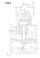
- FIG. 5 is a cross-sectional view showing a clamping mechanism of the vertical type injection molding machine shown in FIG. 1 ;
- FIG. 6 is a front view showing a demolding mechanism of the vertical type injection molding machine shown in FIG. 1 ;
- FIG. 7 is a cross-sectional view taken along line C-C of FIG. 6 ;
- FIG. 8 is a front view illustrating a prior art vertical type injection molding machine.
- FIGS. 1 to 7 One embodiment of the present invention will now be described with reference to FIGS. 1 to 7 .
- a vertical type injection molding machine 1 has a base 5 placed on an installation surface on which the injection molding machine 1 is installed.
- Four support pillars 6 which serve as a support frame, extend vertically, or the direction of arrow Z in FIG. 1 , from a rectangular upper surface of the base 5 .
- Each support pillar 6 has a polygonal cross section.
- the support pillars 6 are arranged at four corners of the upper surface of the base 5 .
- a ceiling portion 7 is provided on the support pillars 6 . That is, the ceiling portion 7 is supported by the support pillars 6 .
- each through hole 12 is located in a portion of the ceiling portion 7 that is between two support pillars 6 arranged along the direction of arrow Y in FIG. 3 .
- a ball screw shaft 13 extending along the direction of arrow Z is passed through each through hole 12 .
- Each ball screw shaft 13 is permitted to rotated in the corresponding through hole 12 .
- the upper end of each ball screw shaft 13 is coupled to a servomotor 14 provided on the ceiling portion 7 , and the lower end of each ball screw shaft 13 is rotatably supported by a bearing (not shown) provided on the base 5 .
- Each ball screw shaft 13 is rotated when the corresponding servomotor 14 is driven.
- the injection molding machine 1 includes a movable body 4 , which is lifted or lowered along the ball screw shafts 13 in response to rotation of the ball screw shafts 13 .
- the movable body 4 includes two ball nuts 15 , a movable base 17 , and a lower mold 20 .
- Each ball nut 15 is screwed onto the corresponding ball screw shaft 13 .
- the movable base 17 is fixed between and supported by the ball nuts 15 and has an upper surface parallel to the installation surface.
- the lower mold 20 is fixed to and supported on the upper surface of the movable base 17 .
- the movable body 4 is at a position close to the base 5 , that is, at a lower position as shown in FIGS. 1 and 3 .
- An upper mold 21 is fixed to the lower surface of the ceiling portion 7 so as to face the lower mold 20 .
- the lower mold 20 and the upper mold 21 are arranged along the vertical direction.
- the upper surface of the lower mold 20 contacts the lower surface of the upper mold 21 as shown in FIG. 2 .
- a mold projection 20 t formed on the upper surface of the lower mold 20 enters a mold recess 210 formed in the lower surface of the upper mold 21 , so that a cavity 22 , which is defined by the mold projection 20 t and the mold recess 21 o , is formed between the upper mold 21 and the lower mold 20 .
- An ejection mechanism is provided in the base 5 to eject a molded article obtained by the lower mold 20 and the upper mold 21 from the upper mold 21 or the lower mold 20 .
- the ejection mechanism is formed by two ejection bars 25 extending from the upper surface of the base 5 .
- the following measures are taken to reduce the load on the servomotors 14 , which actuate the movable body 4 . That is, as shown in FIG. 3 , a hollow space 6 h is formed inside each of the support pillars 6 , which are arranged to surround the upper mold 21 and the movable body 4 including the lower mold 20 .
- a weight 10 is accommodated in each hollow space 6 h . That is, the weights 10 are arranged in the area surrounded by the support pillars 6 . Each weight 10 is allowed to be lifted and lowered in the hollow space 6 h of the corresponding support pillar 6 . Pairs of pulleys 16 are provided on the ceiling portion 7 .
- Each pair of pulleys 16 correspond to one of the support pillars 6 .
- Each weight 10 is connected to the movable body 4 (more exactly, a side of the corresponding ball nut 15 that is opposite to the side facing the movable base 17 ) through two wires 24 , which are placed over the corresponding pair of pulleys 16 .
- Each pair of pulleys 16 includes a pulley shaft 18 rotatably supported by a pair of covers 19 sandwiching the pair of pulleys 16 .
- the pulley shafts 18 extend in the direction of arrow X in FIG. 1 .
- each fastening portion 15 r are fixed to a side of each ball nut 15 that is opposite to the side facing the movable base 17 .
- Each of the two fastening portions 15 r of each ball nut 15 is located on one of the two lines that substantially trisect the side of the ball nut 15 along the direction of arrow Y. Accordingly, the fastening portions 15 r are arranged symmetrically.
- Each fastening portion 15 r corresponds to one of the four pairs of pulleys 16 . That is, each fastening portion 15 r is connected to ends of two wires 24 that are engaged with the corresponding pair of pulleys 16 .
- Ends of two wires 24 placed over each pair of pulleys 16 that are opposite to the ends connected to the corresponding fastening portion 15 r are connected to the corresponding weight 10 , more specifically, to a fastening portion 10 r of the weight 10 .
- First through holes 7 a and second through holes 7 b are formed in the ceiling portion 7 . Portions of the two wires 24 that extend from the corresponding pair of pulleys 16 to the corresponding fastening portion 15 r are received by one of the first through holes 7 a . Portions of the two wires 24 that extend from the corresponding pair of pulleys 16 to the corresponding weight 10 are received by one of the second through holes 7 b.
- the sum of the weights of the weights 10 which pull the movable body 4 through the wires 24 , is set to be the same as the weight of the movable body 4 , that is, the sum of the weights of the ball nuts 15 , the movable base 17 , and the lower mold 20 . Therefore, the weights 10 and the movable body 4 balance with each other. That is, the weights 10 function as a counterweight of the movable body 4 .
- the four weights 10 have the same weight. That is, the weight of each weight 10 is equal to the value obtained by dividing the weight of the movable body 4 by four, which is the number of the weights 10 .
- the weights 10 having the same weight are advantageous in supporting the movable body 4 with the weight 10 in a balanced manner. Since the wires 24 and the pair of pulleys 16 are provided to correspond to each of the weights 10 , the machine 1 is advantageous in dispersing the stress that acts on the wires 24 and the pairs of pulleys 16 due to supporting of the movable body 4 and the weights 10 .
- each clamping mechanism 26 includes a bolt 27 , a drive mechanism 39 , a coil spring 29 , an annular hydraulic washer 30 , which is a cylinder 32 , and a cylindrical body 31 .
- each hydraulic washer 30 is fitted in one of washer holes 30 h formed in the upper surface of the ceiling portion 7 .
- a through hole 27 h extends from the bottom of each washer hole 30 h .
- Each through hole 27 h is coaxial with the corresponding washer hole 30 h and extends through the ceiling portion 7 and the upper mold 21 .
- the center hole of each hydraulic washer 30 fitted in the corresponding washer hole 30 h and the corresponding through hole 27 h form a bolt hole 34 .
- the shank 27 j of a bolt 27 is passed through each bolt hole 34 , and the lower end 27 k of the shank 27 j projects from the lower surface of the upper mold 21 .
- An external thread is formed at the lower end 27 k of each bolt 27 .
- Internal thread holes 20 m are provided at positions on the upper surface of the lower mold 20 that correspond to the lower ends 27 k of the bolts 27 .
- the head 27 t of each bolt 27 is engaged with the periphery of the center hole of the corresponding hydraulic washer 30 .
- a cylindrical body 31 is fitted to the head 27 t of each bolt 27 from above.
- the shape of the inner circumferential surface of the cylindrical body 31 corresponds to the head 27 k .
- the coil spring 29 is arranged between the ceiling surface of the cylindrical body 31 and the head 27 t of the corresponding bolt 27 .
- Each coil spring 29 always urges the corresponding bolt 27 downward.
- Each drive mechanism 39 operates to rotate the corresponding cylindrical body 31 and bolt 27 .
- each drive mechanism 39 includes a plurality of support pillars 33 , which extend upward from the upper surface of the ceiling portion 7 and are arranged to surround the corresponding cylindrical body 31 .
- the support pillars 33 of each drive mechanism 39 support an attachment plate 35 , and a clamping motor 28 is attached to the attachment plate 35 .
- the output shaft 28 s of each clamping motor 28 is connected to the upper surface of the corresponding cylindrical body 31 . Therefore, rotation of the output shaft 28 s of each clamping motor 28 is transmitted to the corresponding bolt 27 through the corresponding cylindrical body 31 .
- Each hydraulic washer 30 receives a piston 36 . More specifically, each cylinder 32 has an annular recess 32 o opened upward, and the piston 36 is accommodated in the annular recess 32 o .
- the annular recess 32 o of each cylinder 32 forms a hydraulic chamber 37 , to which oil is supplied from the outside through an oil passage 38 .
- the piston 36 of each cylinder 32 projects from the cylinder 32 and presses the head 27 t of the corresponding bolt 27 upward. As a result, the bolts 27 move upward.
- the injection molding machine 1 includes a plurality of demolding mechanisms 40 shown in FIGS. 6 and 7 .
- the demolding mechanisms 40 promote separation of the lower mold 20 and the upper mold 21 adhering to a molded article, which is obtained by cooling and solidifying resin in the cavity 22 .
- the demolding mechanisms 40 promote demolding of the lower and upper molds 20 , 21 from each other.
- a fixing portion 41 extends between two support pillars 6 arranged along the direction of arrow X. Each demolding mechanism 40 is provided on one of the fixing portions 41 .
- Each fixing portion 41 has two of the demolding mechanisms 40 on a surface that faces the lower and upper molds 20 , 21 . As shown in FIG.
- each demolding mechanism 40 includes a case 42 attached to the fixing portion 41 and a demolding cylinder 43 accommodated in the case 42 .
- Each demolding cylinder 43 includes a plunger, and a wedge shaped demolding member 44 is provided at the distal end of the plunger.
- Each demolding member 44 is caused to protrude or retreat in response to supply of oil to the corresponding demolding cylinder 43 .
- Demolding holes 45 are provided between the lower mold 20 and the upper mold 21 when they are joined to each other.
- each weight 10 is located at an upper portion in the hollow space 6 h of the corresponding support pillar 6 , while being hung by the wires 24 .
- the movable body 4 is held at the lower position close to the base J.
- the servomotors 14 are driven in the forward direction as injection molding is started, the ball screw shafts 13 are rotated in a predetermined direction. Accordingly, the movable body 4 moves upward.
- the weights 10 which balance with the movable body 4 , minimizes the load on the servomotors 14 moving the movable body 4 upward.
- each bolt 27 projecting from the lower surface of the upper mold 21 eventually contacts the opening of the corresponding internal thread hole 20 m of the lower mold 20 .
- the lower mold 20 and the upper mold 21 are slightly separate from each other.
- the lower end 27 k of each bolt 27 is urged into the corresponding internal thread hole 20 m based on the urging of the bolt 27 by corresponding coil spring 29 .
- each bolt 27 is moved upward against the urging force of the corresponding coil spring 29 , so that the head 27 t of the bolt 27 is separated from the corresponding hydraulic washer 30 .
- the servomotors 14 are stopped.
- each weight 10 is stopped when the operation of the corresponding servomotor 14 is stopped, an inertial force based on the weight of each weight 10 acts on the weight 10 , which momentarily applies a great stress to the corresponding wires 24 .
- the stress that acts on the corresponding wires 24 and the corresponding pair of pulleys 16 is reduced. Therefore, the wires 24 are prevented from being stretched or broken, and the pairs of pulleys 16 are prevented from being deformed.
- each clamping motor 28 is driven in the forward direction with the upper mold 21 and the lower mold 20 contacting each other, the rotation of each clamping motor 28 is transmitted to the head 27 t of the corresponding bolt 27 through the corresponding cylindrical body 31 , so that the bolt 27 is rotated. As a result, the lower end 27 k of each bolt 27 is screwed into the corresponding internal thread hole 20 m as shown in FIG. 2 .
- the corresponding clamping motor 28 is stopped.
- the lower mold 20 is pressed against the upper mold 21 through the bolts 27 .
- an unillustrated injection machine injects molten resin into the cavity 22 , so that the cavity 22 is filled with molten resin. Since the lower mold 20 is pressed against and firmly joined to the upper mold 21 , the injection pressure of the molten metal does not cause the lower mold 20 to be separated from the upper mold 21 .
- the state in which the hydraulic pressure in the hydraulic chambers 37 is high that is, the reinforcement of the joint between the molds 20 , 21 by the cylinders 32 , is maintained until the molten resin in the cavity 22 is cooled and solidified.
- the resin in the cavity 22 is cooled and solidified to obtain a molded article in the cavity 22 .
- each hydraulic chamber 37 is discharged through the corresponding oil passage 38 , so that the hydraulic pressure in the hydraulic chamber 37 is lowered.
- the reinforcement of the joint between the molds 20 , 21 by the cylinders 32 is cancelled.
- the clamping motors 28 are driven in the reverse direction to remove the lower end 27 k of each bolt 27 from the corresponding internal thread hole 20 m .
- the rotation of each clamping motor 28 is transmitted to the head 27 t of the corresponding bolt 27 through the corresponding cylindrical body 31 , so that the bolt 27 is loosened against the urging force of the corresponding coil spring 29 .
- the lower mold 20 is permitted to move.
- the movable body 4 is permitted to descend.
- the mold opening that is, parting of the lower mold 20 and the upper mold 21 from each other, requires a considerable force.
- oil is supplied to the demolding cylinder 43 of each demolding mechanism 40 , so that the demolding member 44 of the demolding mechanism 40 enter the corresponding demolding hole 45 between the lower mold 20 and the upper mold 21 .
- the movable body 4 is pulled upward by the weights 10 through the wires 24 . Since the movable body 4 never free-falls due to its own weight, the servomotors 14 do not need to be driven to maintain the movable body 4 at a predetermined position. This reduces the load on the servomotors 14 .
- the movable body 4 is supported not by a single weight, but by separately arranged multiple weights 10 , each of which is provided with two wires 24 and a pair of pulleys 16 .
- This configuration is advantageous in dispersing the stress acting on the wires 24 and the pairs of pulleys 16 generated by supporting the movable body 4 and the weights 10 , ensuring stable operation of the injection molding by the injection molding machine 1 for an extended period of time.
- Each weight 10 is accommodated in the hollow space 6 h of the corresponding support pillar 6 .
- This configuration is advantageous in reducing the size of the vertical type injection molding machine 1 , and prevents vertical movement of the weights 10 from being hindered by external impediments.
- Each of the two fastening portions 15 r of each ball nut 15 is located on one of the two lines that substantially trisect, along the direction of arrow Y, the side of the ball nut 15 that is opposite to the side facing the movable base 17 .
- the four weights 10 have the same weight. This configuration is advantageous in lifting and lowering the movable body 4 while keeping the movable body 4 in a horizontal position without inclining.
- the number of the support pillars 6 is not limited to four. In place of the support pillars 6 , a structure such as a frame-like body or a wall-like body may be used as a support frame.
- Each weight 10 does not need to be entirely accommodated in the hollow space 6 h of the corresponding support pillar 6 , but may be partly or entirely located outside the support pillar 6 .
- the lift mechanism that lifts and lowers the movable body 4 is not limited to the lift mechanism of the injection molding machine 1 , which includes the ball screw shafts 13 and the ball nuts 15 , but may be a lift mechanism that lifts and lowers the movable body 4 using a chain belt actuated by a motor.
- the lower mold 20 is movable and the upper mold 21 is stationary.
- the molds 20 , 21 may be replaced by a movable upper mold and a stationary lower mold.
- the clamping mechanisms 26 and the ejection mechanisms are modified as necessary.
- the number of the weights 10 is not limited to four. Also, only some of the weights 10 may be arranged in the hollow spaces 6 h , while the other weights 10 are located outside the hollow spaces 6 h of the support pillars 6 .
Landscapes
- Engineering & Computer Science (AREA)
- Manufacturing & Machinery (AREA)
- Mechanical Engineering (AREA)
- Moulds For Moulding Plastics Or The Like (AREA)
- Injection Moulding Of Plastics Or The Like (AREA)
Abstract
Description
Claims (3)
Applications Claiming Priority (2)
| Application Number | Priority Date | Filing Date | Title |
|---|---|---|---|
| JP2008326324A JP5141540B2 (en) | 2008-12-22 | 2008-12-22 | Vertical injection molding machine |
| JP2008-326324 | 2008-12-22 |
Publications (2)
| Publication Number | Publication Date |
|---|---|
| US20100159063A1 US20100159063A1 (en) | 2010-06-24 |
| US8092211B2 true US8092211B2 (en) | 2012-01-10 |
Family
ID=42266495
Family Applications (1)
| Application Number | Title | Priority Date | Filing Date |
|---|---|---|---|
| US12/643,368 Expired - Fee Related US8092211B2 (en) | 2008-12-22 | 2009-12-21 | Vertical type injection molding machine |
Country Status (3)
| Country | Link |
|---|---|
| US (1) | US8092211B2 (en) |
| JP (1) | JP5141540B2 (en) |
| CN (1) | CN101758604B (en) |
Families Citing this family (4)
| Publication number | Priority date | Publication date | Assignee | Title |
|---|---|---|---|---|
| JP4164686B2 (en) * | 2004-08-04 | 2008-10-15 | 株式会社デンソー | Composite product manufacturing method and manufacturing apparatus |
| JP5582191B2 (en) * | 2010-06-21 | 2014-09-03 | 豊田合成株式会社 | Injection molding machine |
| CN111872363A (en) * | 2020-08-05 | 2020-11-03 | 王明 | Mechanical die-closing casting machine |
| CN118342721B (en) * | 2024-05-23 | 2024-10-01 | 淮安华顶鞋业有限公司 | One-step formed rubber and plastic EVA sole processing device and process |
Citations (4)
| Publication number | Priority date | Publication date | Assignee | Title |
|---|---|---|---|---|
| US2431048A (en) * | 1945-10-10 | 1947-11-18 | Wingfoot Corp | Mold press |
| JPH0592432A (en) | 1991-10-03 | 1993-04-16 | Takubo Seiki Seisakusho:Kk | Mold opening and closing device |
| JPH0852756A (en) | 1994-08-12 | 1996-02-27 | Fanuc Ltd | Vertical-vertical injection molding machine |
| US20030077355A1 (en) * | 2001-10-24 | 2003-04-24 | Krauss-Maffei Kunststofftechnik Gmbh | Closing unit for a plastic molding machine |
Family Cites Families (3)
| Publication number | Priority date | Publication date | Assignee | Title |
|---|---|---|---|---|
| JPH01214419A (en) * | 1988-02-23 | 1989-08-28 | N O K Megurasuteitsuku Kk | Release method and device for injection molding machine |
| JP2500142Y2 (en) * | 1992-09-18 | 1996-06-05 | 株式会社新潟鉄工所 | Mold holding device for vertical injection molding machine |
| JPH11333853A (en) * | 1998-05-26 | 1999-12-07 | Mitsubishi Heavy Ind Ltd | Vertical type molding device |
-
2008
- 2008-12-22 JP JP2008326324A patent/JP5141540B2/en active Active
-
2009
- 2009-12-21 US US12/643,368 patent/US8092211B2/en not_active Expired - Fee Related
- 2009-12-22 CN CN200910258168.1A patent/CN101758604B/en not_active Expired - Fee Related
Patent Citations (4)
| Publication number | Priority date | Publication date | Assignee | Title |
|---|---|---|---|---|
| US2431048A (en) * | 1945-10-10 | 1947-11-18 | Wingfoot Corp | Mold press |
| JPH0592432A (en) | 1991-10-03 | 1993-04-16 | Takubo Seiki Seisakusho:Kk | Mold opening and closing device |
| JPH0852756A (en) | 1994-08-12 | 1996-02-27 | Fanuc Ltd | Vertical-vertical injection molding machine |
| US20030077355A1 (en) * | 2001-10-24 | 2003-04-24 | Krauss-Maffei Kunststofftechnik Gmbh | Closing unit for a plastic molding machine |
Also Published As
| Publication number | Publication date |
|---|---|
| JP5141540B2 (en) | 2013-02-13 |
| US20100159063A1 (en) | 2010-06-24 |
| CN101758604A (en) | 2010-06-30 |
| CN101758604B (en) | 2014-05-21 |
| JP2010143197A (en) | 2010-07-01 |
Similar Documents
| Publication | Publication Date | Title |
|---|---|---|
| US8047832B2 (en) | Injection/stretch blow molding machine | |
| EP2135695B1 (en) | Permanent mold casting machine and method for its use | |
| US8092211B2 (en) | Vertical type injection molding machine | |
| CN101386204A (en) | Compression molding table, clamping device and injection molding machine | |
| CN215969895U (en) | Rubber spare forming die and vulcanizer | |
| KR950015722A (en) | Semiconductor Package Molding Device | |
| CN203792634U (en) | Guide column type dual-parting surface mould | |
| JPH085089B2 (en) | Alternate injection molding machine | |
| KR101968009B1 (en) | Non-motorized screw product take-out mold | |
| CN218083935U (en) | Injection mold capable of preventing deformation caused by overlarge local load | |
| JP3477249B2 (en) | Vertical injection molding machine | |
| KR100641790B1 (en) | Impeller Insert Molds for Pumps | |
| KR950004527Y1 (en) | Injection molding apparatus for plastic cap | |
| WO2011161747A1 (en) | Injection molding machine | |
| CN219076344U (en) | Side-tilting prevention rack for injection molding machine | |
| CN222328933U (en) | Machining die for automobile thermostat shell | |
| CN223097984U (en) | Gear die casting die with auxiliary demoulding structure | |
| CN221187337U (en) | Vertical die opening and closing device | |
| CN219968326U (en) | Driving apron well seat steel mould | |
| CN223604780U (en) | Die-resetting, die-overturning and die-testing integrated machine | |
| CN223918534U (en) | Mold core structure of aromatherapy bottle cap mold | |
| CN216938363U (en) | Automobile die-casting die demoulding device | |
| KR102265306B1 (en) | Mold device for producing diffusing lens for display unit | |
| CN211640843U (en) | Mould capable of automatically demoulding | |
| CN210702503U (en) | Casting mold for casting production |
Legal Events
| Date | Code | Title | Description |
|---|---|---|---|
| AS | Assignment |
Owner name: TOYODA GOSEI CO., LTD.,JAPAN Free format text: ASSIGNMENT OF ASSIGNORS INTEREST;ASSIGNORS:TACHIKAWA, SHUNJI;TAKAGI, MUNEHIRO;HAYAKAWA, MINEO;SIGNING DATES FROM 20091216 TO 20091217;REEL/FRAME:023683/0289 Owner name: TOYODA GOSEI CO., LTD., JAPAN Free format text: ASSIGNMENT OF ASSIGNORS INTEREST;ASSIGNORS:TACHIKAWA, SHUNJI;TAKAGI, MUNEHIRO;HAYAKAWA, MINEO;SIGNING DATES FROM 20091216 TO 20091217;REEL/FRAME:023683/0289 |
|
| FEPP | Fee payment procedure |
Free format text: PAYOR NUMBER ASSIGNED (ORIGINAL EVENT CODE: ASPN); ENTITY STATUS OF PATENT OWNER: LARGE ENTITY |
|
| STCF | Information on status: patent grant |
Free format text: PATENTED CASE |
|
| FPAY | Fee payment |
Year of fee payment: 4 |
|
| FEPP | Fee payment procedure |
Free format text: MAINTENANCE FEE REMINDER MAILED (ORIGINAL EVENT CODE: REM.); ENTITY STATUS OF PATENT OWNER: LARGE ENTITY |
|
| LAPS | Lapse for failure to pay maintenance fees |
Free format text: PATENT EXPIRED FOR FAILURE TO PAY MAINTENANCE FEES (ORIGINAL EVENT CODE: EXP.); ENTITY STATUS OF PATENT OWNER: LARGE ENTITY |
|
| STCH | Information on status: patent discontinuation |
Free format text: PATENT EXPIRED DUE TO NONPAYMENT OF MAINTENANCE FEES UNDER 37 CFR 1.362 |
|
| FP | Lapsed due to failure to pay maintenance fee |
Effective date: 20200110 |