US809204A - Slag steam-generator. - Google Patents
Slag steam-generator. Download PDFInfo
- Publication number
- US809204A US809204A US27151405A US1905271514A US809204A US 809204 A US809204 A US 809204A US 27151405 A US27151405 A US 27151405A US 1905271514 A US1905271514 A US 1905271514A US 809204 A US809204 A US 809204A
- Authority
- US
- United States
- Prior art keywords
- slag
- generator
- steam
- carrier
- rotary
- Prior art date
- Legal status (The legal status is an assumption and is not a legal conclusion. Google has not performed a legal analysis and makes no representation as to the accuracy of the status listed.)
- Expired - Lifetime
Links
Images
Classifications
-
- B—PERFORMING OPERATIONS; TRANSPORTING
- B01—PHYSICAL OR CHEMICAL PROCESSES OR APPARATUS IN GENERAL
- B01J—CHEMICAL OR PHYSICAL PROCESSES, e.g. CATALYSIS OR COLLOID CHEMISTRY; THEIR RELEVANT APPARATUS
- B01J8/00—Chemical or physical processes in general, conducted in the presence of fluids and solid particles; Apparatus for such processes
- B01J8/02—Chemical or physical processes in general, conducted in the presence of fluids and solid particles; Apparatus for such processes with stationary particles, e.g. in fixed beds
- B01J8/04—Chemical or physical processes in general, conducted in the presence of fluids and solid particles; Apparatus for such processes with stationary particles, e.g. in fixed beds the fluid passing successively through two or more beds
- B01J8/0492—Feeding reactive fluids
-
- C—CHEMISTRY; METALLURGY
- C10—PETROLEUM, GAS OR COKE INDUSTRIES; TECHNICAL GASES CONTAINING CARBON MONOXIDE; FUELS; LUBRICANTS; PEAT
- C10B—DESTRUCTIVE DISTILLATION OF CARBONACEOUS MATERIALS FOR PRODUCTION OF GAS, COKE, TAR, OR SIMILAR MATERIALS
- C10B39/00—Cooling or quenching coke
- C10B39/04—Wet quenching
Definitions
- My invention relates to an improvement in apparatus for generating steam from hot slag, the object of the invention being to provide improved means for transferring molten slag from a smelting-furnace into a steamgenerator and to provide simple and eflicient means for adjusting the parts to compensate for Wear.
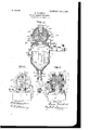
- Figure 1 is a vertical sectional view of an apparatus embodying my invention.
- Fig. 2 is a side view with the boiler broken away.
- Fig. 3 is a sectional view at right angles to Fig. 1 with the boiler broken away.
- a steam-generator which may be of any desired form and construction. It is provided with detachable metal plates or strips 2, which serve to prevent any undue wear of the shell 3 of the generator.
- 4 is the steam-outlet pipe; 5, the feed-water pipe; 6, a safety-valve 7, a valve for controlling the flow of steam, and 8 a water-gage.
- a base-plate 9 having a steam-jacketed cylinder 10 cast integral therewith, or it might be made as a separate casting and bolted to the base-plate.
- the cylinder 10 is made in two sections, each having lugs 10 for the passage of bolts 10 to secure the sections together. Between these lugs and between the sections of the cylinder packing 10 is located. A lin ing 1O is located within the cylinder 10 and is also made in sections separated by packing material. Cylinder 10 is provided with steam-chambers 11, to which steam is fur nished by a pipe 12, leading from the boiler.
- the upper end of the cylinder is provided with a conical feed-chute 11*, through which molten slag is conducted from the smeltingfurnace.
- a rotary slag-carrier 13 having three slag-receptacles 14, situated equidistant apart.
- Standards 15 are secured at opposite ends of the rotary slag-carrier, their lower ends being adjustably secured to the base-plate by bolts 16, while their upper ends are adjustably secured to the cylinder 10 by means of bolts 17.
- the journal-boxes may be adjusted by the bolts 20 so as to permit the rotary slag-carrier to be snugly forced against the valve seat 21, which surrounds the discharge-opening 22, through which the molten charges of slag are introduced into the generator.
- Steam-packing rings 23 may be employed for keeping the rotary slag-carrier steam-tight, and these rings can be adjusted to compensate for wear by means of the bolts 16 17.
- a slide-valve 24 is provided for closing the generator when it is desired to clean or repair the rotary slagcarrier or any of its parts.
- the slag-carrier 13 is made with an axial opening for the reception of a pipe 13 connected with the steamspace of the boiler by mea'nsof a pipe 13*, having a valve 13.
- the pipe 13 is stationary and is provided near its inner end with a lateral hole 13 adapted to communicate successively with ducts 13 in the bottoms of the receptacles 14.
- the operation of the apparatus is as follows: When the rotary slag-carrier is in the position shown in Fig. 1 and in which the open mouth of one of the slag-receptacles registers with the feed-spout, molten slag from a smelting-furnace is introduced into the slagreceptacle until it is nearly full. It will be observed that the mouth of the slag-receptacle is slightly larger in diameter than that of the lower and discharge end of the feedspout.
- This construction is adapted to prevent the molten slag from coming into con-, tact with the periphery of the rotary slag- .carrier, it being highly desirable to prevent lodgment of any slag on the periphery of the rotary slag-carrier, as it would seriously interfere with its operation.
- the slag-carrier is partly rotated, so as to bring the next succeeding receptacle into alinement with the feed spout or chute, and in this way the several slag-receptacles are successively filled with molten slag.
- the discharge-opening in the generator will be closed and prevent any escape of steam from the generator, the rotary slag-carrier serving the purpose of not only carrying the molten slag from the leed-chute to the generator,but also as a rotary valve to prevent the escape of steam from the generator.
- the rotary slagcarrier may be forced down against its seat to compensate for such wear by means of the bolts 20.
- the upper section of the cylinder may be adjusted relatively to the lower section, and the slag-carrier by removing portions of the packing 10 and the lining 10 may be similarly adjusted.
- the finely-divided slag which collected in the bottom of the generator can be discharged therefrom by opening the valve 26 and permitting the slag to fall into chamber 28, and when the latter is filled the valve 26 is closed and the valve 27 opened, and the contents of chamber 28 are discharged into any suitable receptacle or conveyer.
Landscapes
- Chemical & Material Sciences (AREA)
- Organic Chemistry (AREA)
- Chemical Kinetics & Catalysis (AREA)
- Engineering & Computer Science (AREA)
- Materials Engineering (AREA)
- Oil, Petroleum & Natural Gas (AREA)
- Manufacture And Refinement Of Metals (AREA)
Description
No. 809,204. PATENTED JAN. 2, 1906. G. MITCHELL.
SLAG STEAM GENERATOR.
APPLICATION FILED JULY 27, 1905.
WITNESSES UNITED STATES PATENT OFFICE.
Specification of Letters Patent.
Patented Jan. 2, 1906.
Application filed July 2'7, 1905. Serial No. 271,514.
To all whom zit may concern:
Be it known that I, GEORGE MITCHELL, a resident of Los Angeles, in the county of Los Angeles and State of California, have invented certain new and useful, Improvements in Slag Steam-Generators ;and I do hereby declare the following to be a full, clear, and exact description of the invention, such as will enable others skilled in the art to which it appertains to make and use the same.
My invention relates to an improvement in apparatus for generating steam from hot slag, the object of the invention being to provide improved means for transferring molten slag from a smelting-furnace into a steamgenerator and to provide simple and eflicient means for adjusting the parts to compensate for Wear.
WVith this object in view the invention consists in certain novel features of construction and combinations and arrangements of parts, as hereinafter set forth, and pointed out in the claims.
In the accompanying drawings, Figure 1 is a vertical sectional view of an apparatus embodying my invention. Fig. 2 is a side view with the boiler broken away. Fig. 3 is a sectional view at right angles to Fig. 1 with the boiler broken away.
1 represents a steam-generator, which may be of any desired form and construction. It is provided with detachable metal plates or strips 2, which serve to prevent any undue wear of the shell 3 of the generator.
4 is the steam-outlet pipe; 5, the feed-water pipe; 6, a safety-valve 7, a valve for controlling the flow of steam, and 8 a water-gage.
To the top of the generator is secured a base-plate 9, having a steam-jacketed cylinder 10 cast integral therewith, or it might be made as a separate casting and bolted to the base-plate. The cylinder 10 is made in two sections, each having lugs 10 for the passage of bolts 10 to secure the sections together. Between these lugs and between the sections of the cylinder packing 10 is located. A lin ing 1O is located within the cylinder 10 and is also made in sections separated by packing material. Cylinder 10 is provided with steam-chambers 11, to which steam is fur nished by a pipe 12, leading from the boiler. The upper end of the cylinder is provided with a conical feed-chute 11*, through which molten slag is conducted from the smeltingfurnace. Within the cylinder is mounted a rotary slag-carrier 13, having three slag-receptacles 14, situated equidistant apart. Standards 15 are secured at opposite ends of the rotary slag-carrier, their lower ends being adjustably secured to the base-plate by bolts 16, while their upper ends are adjustably secured to the cylinder 10 by means of bolts 17. In each standard is mounted a vertically-adjustable journal-box 18, which supports the journals 19 of the rotary slagcarrier 13. The journal-boxes may be adjusted by the bolts 20 so as to permit the rotary slag-carrier to be snugly forced against the valve seat 21, which surrounds the discharge-opening 22, through which the molten charges of slag are introduced into the generator. Steam-packing rings 23 may be employed for keeping the rotary slag-carrier steam-tight, and these rings can be adjusted to compensate for wear by means of the bolts 16 17. A slide-valve 24 is provided for closing the generator when it is desired to clean or repair the rotary slagcarrier or any of its parts. The slag-carrier 13 is made with an axial opening for the reception of a pipe 13 connected with the steamspace of the boiler by mea'nsof a pipe 13*, having a valve 13. The pipe 13 is stationary and is provided near its inner end with a lateral hole 13 adapted to communicate successively with ducts 13 in the bottoms of the receptacles 14.
The operation of the apparatus is as follows: When the rotary slag-carrier is in the position shown in Fig. 1 and in which the open mouth of one of the slag-receptacles registers with the feed-spout, molten slag from a smelting-furnace is introduced into the slagreceptacle until it is nearly full. It will be observed that the mouth of the slag-receptacle is slightly larger in diameter than that of the lower and discharge end of the feedspout. This construction is adapted to prevent the molten slag from coming into con-, tact with the periphery of the rotary slag- .carrier, it being highly desirable to prevent lodgment of any slag on the periphery of the rotary slag-carrier, as it would seriously interfere with its operation. After one receptacle has been filled the slag-carrier is partly rotated, so as to bring the next succeeding receptacle into alinement with the feed spout or chute, and in this way the several slag-receptacles are successively filled with molten slag. When the filled receptacles are brought into alinement with the dischargeopening 22, the molted charge of slag is discharged into the generator, (assisted by the steam behind it entering by the pipes 13 13 and the instant it strikes the water the slag is comminuted and granulated and transformed into small particles, which gather and are collected in the lower conical end of the generator. The heat stored in the slag is thus quickly transmitted to the water and serves to convert the latter into steam. While a charge of molten slag is being moved from the feed-spout to the discharge-opening it is kept from chilling by the steam-jacketed cylinder 10. After a charge of slag has been discharged into the generator the empty receptacle will be filled with steam, which will be trapped in the receptacle when the latter moved past the discharge-opening; but when the mouth of the receptacle with a charge of steam trappedtherein is moved over the open end of the steam-escape pipe 28 the confined steam will escape through pipe 28 and be conveyed by it into a feed-water heater. When one of the slag-receptacles is in a position to be filled, the discharge-opening in the generator will be closed and prevent any escape of steam from the generator, the rotary slag-carrier serving the purpose of not only carrying the molten slag from the leed-chute to the generator,but also as a rotary valve to prevent the escape of steam from the generator. Should the circular bearing on the lower portion of cylinder 10 become unduly worn, the rotary slagcarrier may be forced down against its seat to compensate for such wear by means of the bolts 20. The upper section of the cylinder may be adjusted relatively to the lower section, and the slag-carrier by removing portions of the packing 10 and the lining 10 may be similarly adjusted. When the lining becomes unduly worn, it may be'readily replaced with a new one. The finely-divided slag which collected in the bottom of the generator can be discharged therefrom by opening the valve 26 and permitting the slag to fall into chamber 28, and when the latter is filled the valve 26 is closed and the valve 27 opened, and the contents of chamber 28 are discharged into any suitable receptacle or conveyer.
Having fully described my invention,what I claim as new, and desire to secure by Letters Patent, is.
1. The combination with a steam-generator having an opening in its top, of a rotary slag-carrier mounted horizontally over said opening and having a series of radial slag-receptacles, and adjustable means for forcing said rotary carrier down upon its seat over the opening in the top of the generator.
2. The combination with a stea1n-generator having a feed-opening in its top and a casing over the generator having a valveseat communicating with said feed-opening, of a rotary slag-carrier disposed in said casing and having a series of radial slag-receptacles, and vertically-adjustable bearings for the journals of said rotary slag-carrier for pressing the latter down upon said valveseat.
3. The combination with a steam-generator having an opening in its top, of a rotary slag-carrier disposed horizontally over said opening and having a series of radial slag-receptacles, standards at respective sides of said carrier, j ournal-boxes in said standards in which the journals of the carrier are mounted, and means in the standards for adjusting said boxes vertically.
In testimony whereof I have signed this specification in the presence of two subscribing witnesses.
GEORGE MITCHELL.
Witnesses:
ROBERT E. MORRISON, GEORGE A. FITCH.
Priority Applications (1)
| Application Number | Priority Date | Filing Date | Title |
|---|---|---|---|
| US27151405A US809204A (en) | 1905-07-27 | 1905-07-27 | Slag steam-generator. |
Applications Claiming Priority (1)
| Application Number | Priority Date | Filing Date | Title |
|---|---|---|---|
| US27151405A US809204A (en) | 1905-07-27 | 1905-07-27 | Slag steam-generator. |
Publications (1)
| Publication Number | Publication Date |
|---|---|
| US809204A true US809204A (en) | 1906-01-02 |
Family
ID=2877685
Family Applications (1)
| Application Number | Title | Priority Date | Filing Date |
|---|---|---|---|
| US27151405A Expired - Lifetime US809204A (en) | 1905-07-27 | 1905-07-27 | Slag steam-generator. |
Country Status (1)
| Country | Link |
|---|---|
| US (1) | US809204A (en) |
Cited By (2)
| Publication number | Priority date | Publication date | Assignee | Title |
|---|---|---|---|---|
| US20050028190A1 (en) * | 2002-02-11 | 2005-02-03 | Rodriguez Arturo A. | Management of television advertising |
| WO2006014567A2 (en) | 2004-07-08 | 2006-02-09 | Pneumrx, Inc. | Pleural effusion treatment device, method and material |
-
1905
- 1905-07-27 US US27151405A patent/US809204A/en not_active Expired - Lifetime
Cited By (2)
| Publication number | Priority date | Publication date | Assignee | Title |
|---|---|---|---|---|
| US20050028190A1 (en) * | 2002-02-11 | 2005-02-03 | Rodriguez Arturo A. | Management of television advertising |
| WO2006014567A2 (en) | 2004-07-08 | 2006-02-09 | Pneumrx, Inc. | Pleural effusion treatment device, method and material |
Similar Documents
| Publication | Publication Date | Title |
|---|---|---|
| LU100534B1 (en) | Drying hopper as well as grinding and drying plant comprising such | |
| US809204A (en) | Slag steam-generator. | |
| US581908A (en) | Joseph franklin gent and richard thomas gent | |
| US809123A (en) | Apparatus for generating steam from hot slag. | |
| US2326005A (en) | Feeding mechanism | |
| US1001660A (en) | Rotary-disk drier. | |
| FR2527478A1 (en) | Cyclone separator - comprising gas-tight vertical cylindrical chamber into which gas enters tangentially at top | |
| US711331A (en) | Slag steam-generator. | |
| US836888A (en) | Feeding mechanism for gas-producers. | |
| US1964614A (en) | Gas producer | |
| US2252802A (en) | Gas producer | |
| US399794A (en) | Gas-producer | |
| US1303470A (en) | gillette | |
| US850241A (en) | Centrifugal machine. | |
| US968870A (en) | Slag steam-generator. | |
| US711332A (en) | Slag steam-generator. | |
| US916176A (en) | Ore-smelter. | |
| US594539A (en) | The nor | |
| US449359A (en) | Desiccating apparatus | |
| US1093500A (en) | Sterilizer. | |
| US203446A (en) | Improvement in metallurgic gas-generators | |
| US623231A (en) | Multitubular ore-cooler | |
| US561175A (en) | Drier | |
| US623230A (en) | Rotary ore-cooler | |
| US395580A (en) | Kison |