US80917A - Charles - Google Patents
Charles Download PDFInfo
- Publication number
- US80917A US80917A US80917DA US80917A US 80917 A US80917 A US 80917A US 80917D A US80917D A US 80917DA US 80917 A US80917 A US 80917A
- Authority
- US
- United States
- Prior art keywords
- screw
- cutter
- cutting
- charles
- shoulder
- Prior art date
- Legal status (The legal status is an assumption and is not a legal conclusion. Google has not performed a legal analysis and makes no representation as to the accuracy of the status listed.)
- Expired - Lifetime
Links
- XEEYBQQBJWHFJM-UHFFFAOYSA-N iron Substances [Fe] XEEYBQQBJWHFJM-UHFFFAOYSA-N 0.000 description 7
- 229910052742 iron Inorganic materials 0.000 description 5
- 238000010276 construction Methods 0.000 description 2
- 239000002184 metal Substances 0.000 description 1
- 229910052751 metal Inorganic materials 0.000 description 1
Images
Classifications
-
- B—PERFORMING OPERATIONS; TRANSPORTING
- B27—WORKING OR PRESERVING WOOD OR SIMILAR MATERIAL; NAILING OR STAPLING MACHINES IN GENERAL
- B27H—BENDING WOOD OR SIMILAR MATERIAL; COOPERAGE; MAKING WHEELS FROM WOOD OR SIMILAR MATERIAL
- B27H5/00—Manufacture of tubes, coops, or barrels
- B27H5/08—Finishing barrels, e.g. cutting grooves
Definitions
- This invention relates to certain improvements in eoopers croze, and consists in a simple construction of the cutting-iron, whereby it is readily attached to and detached from thc-adjusting-screw when desired, and yet is securely held when in use, as will he described hereinafter.
- Figure 1 represents a plan view of my invention
- Figures 2, 3, and 4 represent views of parts detached.
- i a represents a socket or groove running diagonally across it, in which tits the upper part of the cuttingiron B, which latter is made oi' proper form to slide easily therein.
- l represents an arm extending from the upper end of the cutting-iron B, as shown, upon which is placed the shoulder bl.
- b2 represents a flat spring fastened to the lower side of the iron, and extepding out in line with shoulder b.
- a socket is made in which rests the button oi screw C.
- the lower or cutting part of the instrument is made V-shaped, for the purpose of' cutting the groove i'n the staves. If desired, this part may be made square in form, for the purpose oi'V cutting a corresponding groove.
- e c represent its bearings, provided with corresponding screw-threads. .By turning the screw C, the cutter is thrust forward oi" drawn back, as may be desired. if
- D represents another screw, placed above the cutter, and operated similarly to C, excepting thatvit is not attached in any way to the cutter.
- a bearing-surface of different metal may he used if desired, for the cutter to slide upon, hut this is not-essential.
- the iron is easily attached to the screw by simply pushing the former forcibly against b2 and shoulder blgin which case the spring b2 yields sufficiently to permit' the head of the screw C to pn-ssdiy 'the shoulder b1 and rcstin the socket.
- its Free end shouldl he pulled'up from the croze (the holding-screw having been'loosened) far enough to force spring b2 open, by which means the head of screw C is permitted to slip out.
- the cutter B is adjusted in or out, aus may be desired, by means of the screw C, after which the screw D is set down upon it, hy which ineansthe cutter is rigidly held in place.
Landscapes
- Engineering & Computer Science (AREA)
- Life Sciences & Earth Sciences (AREA)
- Manufacturing & Machinery (AREA)
- Mechanical Engineering (AREA)
- Wood Science & Technology (AREA)
- Forests & Forestry (AREA)
- Processing Of Stones Or Stones Resemblance Materials (AREA)
Description
@uiten gi-.tss etant @ffice Letters Patent No. 8 ,917, dated August 11, 1868.
IMPROVEMENT IN GOOPERS ORQZE.
@igt tlgemrle feierten in im time teiter irtnit mit making glatt nf tige time.
TO ALL WHOM IT MAY CONCERN:
Be it known that I, CHARLES O. COOK, of Rockford, \in the county of Winnebago, and State of Illinois, have invented a new and improved Coopers Croze; and I do hereby declare that the following is a full and exact description of the same, reference being had to the accompanying drawings, and to the letters of refer ence marked thereon. y l
This invention relates to certain improvements in eoopers croze, and consists in a simple construction of the cutting-iron, whereby it is readily attached to and detached from thc-adjusting-screw when desired, and yet is securely held when in use, as will he described hereinafter.
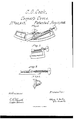
Figure 1 represents a plan view of my invention, and Figures 2, 3, and 4 represent views of parts detached.
In the drawings- A represents the main part of the instrument, the outer edge of which is curved,.to iit the inside of a barrel, and is V-shaped, as shown. l
i a represents a socket or groove running diagonally across it, in which tits the upper part of the cuttingiron B, which latter is made oi' proper form to slide easily therein. l represents an arm extending from the upper end of the cutting-iron B, as shown, upon which is placed the shoulder bl. v
b2 represents a flat spring fastened to the lower side of the iron, and extepding out in line with shoulder b. By this arrangement a socket is made in which rests the button oi screw C. `The lower or cutting part of the instrument -is made V-shaped, for the purpose of' cutting the groove i'n the staves. If desired, this part may be made square in form, for the purpose oi'V cutting a corresponding groove. i
C represents' a screw, the button of which ts into the socket of the cutter B, as before described, and revolves 4freely therein. y
e c represent its bearings, provided with corresponding screw-threads. .By turning the screw C, the cutter is thrust forward oi" drawn back, as may be desired. if
D represents another screw, placed above the cutter, and operated similarly to C, excepting thatvit is not attached in any way to the cutter. A bearing-surface of different metal may he used if desired, for the cutter to slide upon, hut this is not-essential.
lThis instrument should be attached to the wooden guide, constructed as usual, by means of the lugs a: x.
From this description the operation of my invention will be readily understood.` The iron is easily attached to the screw by simply pushing the former forcibly against b2 and shoulder blgin which case the spring b2 yields sufficiently to permit' the head of the screw C to pn-ssdiy 'the shoulder b1 and rcstin the socket. When itis desired to detach the ironfor any purpose, its Free end shouldl he pulled'up from the croze (the holding-screw having been'loosened) far enough to force spring b2 open, by which means the head of screw C is permitted to slip out. The cutter B is adjusted in or out, aus may be desired, by means of the screw C, after which the screw D is set down upon it, hy which ineansthe cutter is rigidly held in place.
.This construction allows the cutter to be quickly and' easily detached, while at the same time it is firmly held when in use. y
Having thus fully described my invention, what I claim as new, and desire to secure by Letters Patent, is
The arm b, shoulder b1, and spring b2 of cutting-iron B, when combined and operated in connection with the head of screw C, as and for thepurpose described. w
This speciiication signed and witnessed, this third day of April, 1868.
' CHARLES 0. COOK.
Witnesses:
OLIvnn A. PENNornn, G. W. FORD.
Publications (1)
| Publication Number | Publication Date |
|---|---|
| US80917A true US80917A (en) | 1868-08-11 |
Family
ID=2150412
Family Applications (1)
| Application Number | Title | Priority Date | Filing Date |
|---|---|---|---|
| US80917D Expired - Lifetime US80917A (en) | Charles |
Country Status (1)
| Country | Link |
|---|---|
| US (1) | US80917A (en) |
Cited By (1)
| Publication number | Priority date | Publication date | Assignee | Title |
|---|---|---|---|---|
| US20030177647A1 (en) * | 2002-03-20 | 2003-09-25 | Moore Edward M. | Miniature roller plane for making precision cuts in flat and concave work surfaces |
-
0
- US US80917D patent/US80917A/en not_active Expired - Lifetime
Cited By (1)
| Publication number | Priority date | Publication date | Assignee | Title |
|---|---|---|---|---|
| US20030177647A1 (en) * | 2002-03-20 | 2003-09-25 | Moore Edward M. | Miniature roller plane for making precision cuts in flat and concave work surfaces |
Similar Documents
| Publication | Publication Date | Title |
|---|---|---|
| US80917A (en) | Charles | |
| US41797A (en) | Improvement in slitting-gages | |
| US262218A (en) | Anton geiger | |
| US987918A (en) | Garden-tool. | |
| US135692A (en) | Improvement in scissors | |
| US91806A (en) | Nathan woodbury | |
| US76464A (en) | Self -and chauncbt johnson | |
| US73657A (en) | Eli as shopbell | |
| US80389A (en) | Charles christian | |
| US79509A (en) | smith | |
| US49577A (en) | Improvement in instruments for stripping sugar-cane | |
| US81292A (en) | Improved coeksceew | |
| US73723A (en) | Improvement in spoke-shaves | |
| US81497A (en) | Improvement in box-oeenebs | |
| US94336A (en) | Improved skate-runner | |
| US54774A (en) | Improvement in mode of attach ing circular saws to their arbors | |
| US82450A (en) | John blake take | |
| US73759A (en) | Improvement in gauge poe sewing-machines | |
| US99308A (en) | Improvement in straw-cutters | |
| US45907A (en) | Improved whitewash-brush | |
| US86956A (en) | Improvement in boring-faucets | |
| US107507A (en) | Improvement in casters | |
| US82383A (en) | Improved mop-head | |
| US93457A (en) | Improvement in making- bungs | |
| US105583A (en) | Improvement in can-openers |