US809176A - Landing-chair for mining-cages. - Google Patents
Landing-chair for mining-cages. Download PDFInfo
- Publication number
- US809176A US809176A US24711405A US1905247114A US809176A US 809176 A US809176 A US 809176A US 24711405 A US24711405 A US 24711405A US 1905247114 A US1905247114 A US 1905247114A US 809176 A US809176 A US 809176A
- Authority
- US
- United States
- Prior art keywords
- cage
- chairs
- lever
- platform
- landing
- Prior art date
- Legal status (The legal status is an assumption and is not a legal conclusion. Google has not performed a legal analysis and makes no representation as to the accuracy of the status listed.)
- Expired - Lifetime
Links
Images

Classifications
-
- B—PERFORMING OPERATIONS; TRANSPORTING
- B66—HOISTING; LIFTING; HAULING
- B66B—ELEVATORS; ESCALATORS OR MOVING WALKWAYS
- B66B17/00—Hoistway equipment
- B66B17/34—Safe lift clips; Keps
Definitions
- My invention relates to landing-chairs for mining-cages in which the chairs are pivotally appended to the cage, thus requiring but one set of chairs to land the cage at any de sired point of landing.
- the objects of my invention are to provide landing-chairs for mining-cages in which there are no springs nor intricate contrivances required to operate the chairs, one which can be conveniently operated from the cage or from any desired point of landing that is, at the collar of the shaft at any level of the mine or at any point between the lev- I els where it is desired toland the cageone in which there is provided automatic means for operating the chairs at any point where regular landings are to be made, including the collar of the shaft, also one in which the weight of the cage and its contents rest upon solid forgings forming the chairs and not upon pivots, as is the case with most landingchairs heretofore invented, and one in which the chairs are placed in an operative position and displaced from that position by simple means or gravity.
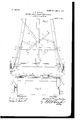
- FIG. 1 is an elevation of an, ordinary miningcage embodying my invention.
- Fig. 2 is a fragmental bottom view of Fig. 1.
- Fig. 3 is an elevation of a mining-cage having my new landing-chairs attached thereto, showing means for operating the chairs at one of the levels in a mine.
- Fig. 4 is a modified form of Fig. 3, showing different means for placing the chairs in an operative position at the landing.
- Fig. 5 shows a cage embodying my invention and the means for operating same at the collar of the shaft.
- Fig. 6 is a plan view of the platform of the cage looking down from line a a of Fig. 3.
- Fig. 7 is a view of the chairs or forgings.
- 10 represents the corner posts or bars of the cage, there being in the preferred construction four of these bars.
- These posts or bars are arranged in sets of two, one set on each side of the platform 1 1, and are secured thereto.
- Each set is inwardly inclinedthat is, the posts of each set are inclined toward each other at the upper ends thereof, though the sets remain vertical, the distance between the sets at the bottom and at the top being in the preferred construction e ual.
- the upper ends of these triangularly-s aped sets of posts may be secured to any suitable contrivance of ordinary construction, as I do not claim anything thereon.
- the platform 11 of the cage has a downturned flange 15.
- the longitudinal crossbars 16 are adapted to be secured to the posts or bars 10 and to extend across the sides of the cage. They may also be secured to the central posts 12. In some instances these bars 16 may be dispensed with.
- the chairs or forgings are adapted to be pivoted to the corner-bars 10. These chairs are constructed with right-angled arms 18 the chairs are pivotally hung to the cage.
- the right-angled arms of the chairs extend above the point of pivot and are provided with eyes 21. I
- the lever 22 represents a lever fulcrumed to one of the central posts 12.
- the lever is adapted to be placed on either side of the cage, whichever will be most convenient and practical for the shaft in which the cage is to operate. It has a downwardly-appended part 23, forming a weight providing means for maintaining the lever 22 in a vertical position when so desired.
- These arms 24 are in the preferred construction bent outwardly, as illus- ICO trated in Figs. 2 and 6.
- Pivotally connected with these arms 24 are bars 26, which are also pivotally connected to the upper ends of the arms of the chairs by means of the eyes in said upper ends, (designated by 21 and hereinbefore referred to.)
- the chairs may land in seats 27, formed by recesses in the timbers 28 of the shaft at the different levels or at any desired point of landing, asillustrated in Figs. 1, 3, and 4 of the drawings.
- These recesses may be fprovided with plates 29, (shown in Fig. 1 o the drawings,) which may be constructed of suitable metal and are adapted to prevent wearing the timbers in which the recesses are made.
- plates 29, shown in Fig. 1 o the drawings,
- This is one manner of constructing the landing which is adapted to bring the platform of the cage level with the surface of the place desired to land.
- Another method is to land on the surfaces of the level or collar of the shaft, as illustrated in Fig. 5 of the drawings. When the cage is landed, as illustrated in Fig.
- the track on which the tramcars are operated may be raised in any suitable manner, so that the top of the track will be at grade with the top of the platform of the cage or with the tracks placed thereon, as will be done in some instances. It is comprehensible that there is nothing new in the construction of the cage, as my new landing-chairs can be attached to any mining-cage of ordinary construction.
- a lever 30 is fulcrumed to a post 31, which can be secured to the ordinary timbers of the mine or can be placed in the desired position at the collar of the shaft.
- the lever 30 is provided with a weight 32, adapted to maintain the lever in substantially the position illustrated by the dotted lines in Fig. 3 when it is not in use at a level in the mine. It is obvious that by retaining the lever in the position indicated by the dotted lines will keep it out of the pas sage-way of the shaft, it being formed with a bend, as illustrated in Fig.
- FIG. 5 shows a vertical arm 34 extending upward from the lever 30, which is provided with an eye, to which is attached a rope 35.
- This rope is adapted to extend to a point within convenient reach of the engineer, who can when desiring to lower the cage raiseit to a height sufficient to pass the lever. Then by means of the rope the lever can be brought to the position indicated by the dotted lines in Fig. 5, which will allow the cage to descend, as the weight of the chairs, in connection with the weight 23, provided on the lever 22, will tend to bring the lever 22 to a vertical position and the chairs to the inoperative position, as illustrated inFig. 3 of the drawings.
- the modified construction illustrated in Fig.
- a lever 36 is secured to the timbers of the shaft at the lower part of the level in the mine or at any point where it is desired to land the cage.
- the lever is constructed with a right-angled arm at the end, as illustrated.
- the connectingbars 26 are pivoted to the extension-arms 24 at different points than when the preferred form of operating the chairs is used that is, the distance between the points where the said connecting-bars 26 are pivoted to the arms 24 is greater in the mo dified form.
- This change in pivoting the said bars prevents the arms and bars from assuming a position of dead-center essential to the operation of the modified form, inasmuch as the actuating of the chairs to place them in operative position takes place on the lower end of the chair-forgings, as illustrated.
- This modified construction can also be converted into automatic means for placing the chairs in operative position by simply placing a pin above the lever, which will maintain it in position similar to that shown in Fig. 4 of the drawings, and byplacing a weight thereon.
- the operation of a mining-cage supplied with my new landing-chairs will be in the preferred construction substantially as follows:
- the cage is raised and lowered by any suitable means. If it is desired to land the cage at either of the levels inthe mine, levers 30 are provided in each level, so that the cage may be landed either from the cage or from the level. If it is desired to place the chairs in operative position from the cage,it is doneby means of the lever 22, as hereinbefore stated. If it is desired to land the cage from the level or from some other predetermined point, where a suitable lever 30 has been provided, it is done by simply bringing the lever 30 into substantially a horizontal position, (illustrated in Fig.
- the construction of my invention is such that in case the chairs come in contact with the seats 27 or with the surfaces of the landing, as shown in Fig. 5, before the chairs have swung outwardly the maximum dis tance the downward pressure upon the chairs causing them to spread, bringing the chairs in full operative position, as shown in Fig. 1, without any further manipulation of the means for actuating the chairs.
- the construction of the means for placing the chairs in the operative position is such that the connecting-bars and arms assume a position of dead point or dead-center when the chairs are in the inoperative position, as illustrated in Fig. 3 of the drawings.
- This provision is another essential feature of my invention, as it forms a rigid lock for the chairs and prevents them from swinging outwardly when it is not desired to land the cage.
- a cage, and chairs pivotally appended to said cage, above the platform thereof and having horizontal portions below their pivots with seats disposed beneath said platform of the cage.
- a cage, and chairs pivotally appended to said cage with horizontal portions below their pivots, the point of pivot being above the platform thereof and a manually-operable lever pivotally connected with said chairs above their pivots.
- a cage, and chairs having right-angled arms provided with seats below their pivots; and with elongated eyes at their pivotal sup- &
- a cage chairs pivotally attached to said cage above the platform thereof, and manually-operable means above the pivots of the chairs for placing said chairs in an operative position.
- a cage, and chairs pivoted to the cage above the platform appending the chairs below the said platform, and manuallyoper able means above the pivots of the chairs for actuating the same adapted to place the chairs in an operative position.
- a cage, chairs having central raised parts forming seats and having right-angled arms provided with elongated eyes by means of which the chairs are pivotally appended to the said cage at a point above the platform thereof, and means for placing said chairs in the operative position.
- a cage, chairs pivotally connected thereto, and having horizontal portions with seats, means for actuating said chairs comprising a lever fulcru med to said cage, arms extending from said lever, and connecting-bars pivoted to said arms and to said chairs.
- a cage, chairs for said cage pivoted thereto, above the platform thereof, means above the pivots of said chairs for placing said chairs in an operative position comprising the lever fulcrumed to the said cage and toggle-arms pivoted to said lever and to the said chairs, and a lever secured to a substantial support adjacent to the passage-way for the cage.
- a cage, and chairs pivotally appended to the cage above and independent of the platform thereof and having portions forming seats therefor.
- a cage, and chairs pivotally appended to said cage above and independent of the platform thereof and having seats below the platform.
- a cage, and chairs having the central parts of the-main portions raised forming seats and having right-angled arms provided with. elongated eyes; the said chairs'adapted to be appended to the cage above the platform thereof by means of axial pins extending through the elongated eyes in the said right-angled arms in a manner adapted to bring the seats below the, platform of the cage, and means for placing the chairs in an operative position.
- a cage, and chairs pivotally appended to said cage above the platform and havingmanually-operable means extended above their pivots and connected with said chairs by means pivotally attached directly thereto for cooperation with actuating means therefor.
- A'cage, and chairs having horizontal portions below the platform of the cage and right-angled arms extending upwardly therefrom, and said horizontal portions formed with seats appended below the platform of the cage, the said right-angled arms being pivotally attached to the posts of the cage above the platform thereof.
Landscapes
- Chairs For Special Purposes, Such As Reclining Chairs (AREA)
Description
PATENTED JAN. 2, 1906.
G. H. DBNTON.
LANDING CHAIR FOR MINING CAGES. AEPLIGATION1:ILED FEB.24,1905.
2 SHEETS-SHEET l.
Fig.1.
ITO-809,176. PATENTED JAN. 2, 1906. G. H. BENTON.
LANDING CHAIR FOR MINING GAGES.
APPLICATION FILED FEB.24,1905.
2 8HEETS-SHEET 2.
M' W77 MM Winessm [/1 1 29/2602 UNITED sTATEs PATENT OFFICE.
LANDING-CHAIR FOR MINING-CAGES.
Specification of Letters Patent.
Patented Jan. 2, 1906.
Application filed February 24, 1905 Serial No. 247.114.
T0 ZZ whom it may concern;
Be it known that I, GILBERT HENRY DEN- TON, acitizen of the United States, residing in the city and county of Denver and State of Colorado, have invented certain new and useful Improvements in Landing-Chairs for Mining-Cages, of which the following is a specification.
My invention relates to landing-chairs for mining-cages in which the chairs are pivotally appended to the cage, thus requiring but one set of chairs to land the cage at any de sired point of landing.
The objects of my invention are to provide landing-chairs for mining-cages in which there are no springs nor intricate contrivances required to operate the chairs, one which can be conveniently operated from the cage or from any desired point of landing that is, at the collar of the shaft at any level of the mine or at any point between the lev- I els where it is desired toland the cageone in which there is provided automatic means for operating the chairs at any point where regular landings are to be made, including the collar of the shaft, also one in which the weight of the cage and its contents rest upon solid forgings forming the chairs and not upon pivots, as is the case with most landingchairs heretofore invented, and one in which the chairs are placed in an operative position and displaced from that position by simple means or gravity.
I attain the foregoing objects by the construction illustrated in the drawings, forming a part of this application, in which similar numerals of reference indicate corresponding parts in all the figures, and in which Figure 1 is an elevation of an, ordinary miningcage embodying my invention. Fig. 2 is a fragmental bottom view of Fig. 1. Fig. 3 is an elevation of a mining-cage having my new landing-chairs attached thereto, showing means for operating the chairs at one of the levels in a mine. Fig. 4 is a modified form of Fig. 3, showing different means for placing the chairs in an operative position at the landing. Fig. 5 shows a cage embodying my invention and the means for operating same at the collar of the shaft. Fig. 6 is a plan view of the platform of the cage looking down from line a a of Fig. 3. Fig. 7 is a view of the chairs or forgings.
In more fully referring to the drawings,10 represents the corner posts or bars of the cage, there being in the preferred construction four of these bars. These posts or bars are arranged in sets of two, one set on each side of the platform 1 1, and are secured thereto. Each set is inwardly inclinedthat is, the posts of each set are inclined toward each other at the upper ends thereof, though the sets remain vertical, the distance between the sets at the bottom and at the top being in the preferred construction e ual. The upper ends of these triangularly-s aped sets of posts may be secured to any suitable contrivance of ordinary construction, as I do not claim anything thereon.
12 represents central vertical posts, one of which is provided on each side of the cage, being secured to the platform 11 and to the contrivance at the upper end. Guide-plates 13 are secured to the central posts 12, adapted to operate in connection with the guidebars 14, which are placed on the sides of the shaft, as illustrated in Fig. 6 of the drawings.
The platform 11 of the cage has a downturned flange 15. The longitudinal crossbars 16 are adapted to be secured to the posts or bars 10 and to extend across the sides of the cage. They may also be secured to the central posts 12. In some instances these bars 16 may be dispensed with.
The chairs or forgings are adapted to be pivoted to the corner-bars 10. These chairs are constructed with right-angled arms 18 the chairs are pivotally hung to the cage.
The right-angled arms of the chairs extend above the point of pivot and are provided with eyes 21. I
22 represents a lever fulcrumed to one of the central posts 12. The lever is adapted to be placed on either side of the cage, whichever will be most convenient and practical for the shaft in which the cage is to operate. It has a downwardly-appended part 23, forming a weight providing means for maintaining the lever 22 in a vertical position when so desired. Secured to the lever 22 and oppositely disposed at right angles therefrom are arms 24, provided near their extremities with nipples 25. These arms 24 are in the preferred construction bent outwardly, as illus- ICO trated in Figs. 2 and 6. Pivotally connected with these arms 24 are bars 26, which are also pivotally connected to the upper ends of the arms of the chairs by means of the eyes in said upper ends, (designated by 21 and hereinbefore referred to.)
It is obvious that the chairs may land in seats 27, formed by recesses in the timbers 28 of the shaft at the different levels or at any desired point of landing, asillustrated in Figs. 1, 3, and 4 of the drawings. These recesses may be fprovided with plates 29, (shown in Fig. 1 o the drawings,) which may be constructed of suitable metal and are adapted to prevent wearing the timbers in which the recesses are made. This is one manner of constructing the landing which is adapted to bring the platform of the cage level with the surface of the place desired to land. Another method is to land on the surfaces of the level or collar of the shaft, as illustrated in Fig. 5 of the drawings. When the cage is landed, as illustrated in Fig. 5, the track on which the tramcars are operated may be raised in any suitable manner, so that the top of the track will be at grade with the top of the platform of the cage or with the tracks placed thereon, as will be done in some instances. It is comprehensible that there is nothing new in the construction of the cage, as my new landing-chairs can be attached to any mining-cage of ordinary construction.
- I have hereinbefore referred to the means for operating the chairs, the preferred construction ofwhich is illustrated in Figs. 3 and 5 of the drawings, in which a lever 30 is fulcrumed to a post 31, which can be secured to the ordinary timbers of the mine or can be placed in the desired position at the collar of the shaft. The lever 30 is provided with a weight 32, adapted to maintain the lever in substantially the position illustrated by the dotted lines in Fig. 3 when it is not in use at a level in the mine. It is obvious that by retaining the lever in the position indicated by the dotted lines will keep it out of the pas sage-way of the shaft, it being formed with a bend, as illustrated in Fig. 6 of the drawings, adapted to place the end which will extend into the shaft when in use to the side of the cage in the space formed by the guide-bars 14.. It is manifest that this provision places no obstruction in the way of the cage when it is being raised or lowered unless it is desired to land it, in which event the lever can be operated and brought to the position indicated in Fig. 3, which will bring the end extending into the shaft in contact with the nipples 25 on the extension-arms 24 of the lever 22, and thus actuating said lever and bring it, as well as the connecting-bars pivoted thereto, into the positionillustrated in Figs. 1, 4, and 5 of the drawings, which throws the landingchairs outwardly and into a position which will bring them in contact with the seats provided in the recesses 27 or with the surface at the point of landing, as illustrated in Fig. 5 of the drawings. If it is desired to establish a regular landing-place, the lever described in the foregoing can readily be converted into automatic means for actuating the lever and connectingrods, which in turn place landing-chairs in an operative position by placing a pin 33 into some substantial part of the timbers, as illustrated in Fig. 5 of the drawings. Provisions for the insertion of this pin 33 may be made at any of the levels or at any point where it is desired to land the cage. The illustration of the lever in Fig. 5 shows a vertical arm 34 extending upward from the lever 30, which is provided with an eye, to which is attached a rope 35. This rope is adapted to extend to a point within convenient reach of the engineer, who can when desiring to lower the cage raiseit to a height sufficient to pass the lever. Then by means of the rope the lever can be brought to the position indicated by the dotted lines in Fig. 5, which will allow the cage to descend, as the weight of the chairs, in connection with the weight 23, provided on the lever 22, will tend to bring the lever 22 to a vertical position and the chairs to the inoperative position, as illustrated inFig. 3 of the drawings. In the modified construction (illustrated in Fig. 4) a lever 36 is secured to the timbers of the shaft at the lower part of the level in the mine or at any point where it is desired to land the cage. The lever is constructed with a right-angled arm at the end, as illustrated. By means of this lever 36 the chair can be placed in operative position, as the right-angled arm comes in contact with the forging at one side, drawing it outward into operative position, which movement operates the chair at the opposite end of the cage by means of the connecting-bars 26 and the arms 24, forming a part of the lever 22, as will be made manifest in the drawings. When this modified construction is used, the connectingbars 26 are pivoted to the extension-arms 24 at different points than when the preferred form of operating the chairs is used that is, the distance between the points where the said connecting-bars 26 are pivoted to the arms 24 is greater in the mo dified form. (Represented by Fig. 4.) This change in pivoting the said bars prevents the arms and bars from assuming a position of dead-center essential to the operation of the modified form, inasmuch as the actuating of the chairs to place them in operative position takes place on the lower end of the chair-forgings, as illustrated. This modified construction can also be converted into automatic means for placing the chairs in operative position by simply placing a pin above the lever, which will maintain it in position similar to that shown in Fig. 4 of the drawings, and byplacing a weight thereon.
. as shown in Fig. 5 of the drawings.
The operation of a mining-cage supplied with my new landing-chairs will be in the preferred construction substantially as follows: The cage is raised and lowered by any suitable means. If it is desired to land the cage at either of the levels inthe mine, levers 30 are provided in each level, so that the cage may be landed either from the cage or from the level. If it is desired to place the chairs in operative position from the cage,it is doneby means of the lever 22, as hereinbefore stated. If it is desired to land the cage from the level or from some other predetermined point, where a suitable lever 30 has been provided, it is done by simply bringing the lever 30 into substantially a horizontal position, (illustrated in Fig. 3 of the drawings,) when it will come in contact with the nipples 25 on the arms24 and will place the chairs in an operative position, as shown in Fig. 1. When it is desired to have a regular landing-place at any of the levels, the lever 30 is converted into automatic means by placing a pin 33 above thelever, as illustrated in Fig. 5. I/Vhen this provision has been made, the cage in its descent brings the nipples 25 in contact with the lever 30, which throws the chairs into operative position, as shown in Fig. 5 of the drawings. When the cage is raised, the weight of the chairs and the additional weight 23, forming a part of the lever 22, displaces the chairs from the operative position and brings them into the inoperative position, (fully illustrated in Fig. 3 of the drawings,) permitting the cage to be raised and lowered freely. The landing at the top or collar of the shaft is accomplished by the means illustrated in Fig. 5, wherein the lever 30 is provided with an upwardly-extending arm 34, to which is attached a rope extending to the engineer or operator having charge of raising and lowering the cage. The provision of the rope is of utility, as it enables the engineer or operator to throw the lever 30 into a position out of the way of the downward passage of the cage. When the cage ascends, no attention need be given to the lever 30, as it operates automatically and places the chairs in the operative position as the cage descends after having been raised to the maximum height, as illustrated in Fig. 5. The chairs are displaced from the operative position under the action of gravity alone.
One feature of my invention that I dis tinctly emphasize is that the weight of the cage and its contents rest upon the seats of the chairs which come in contact with the bottom of the cage at the reinforced parts, where the angle bars forming part of the flanges 15 are riveted to the platform 11 of the cage. The chairs rest upon metal seats 29, provided in recesses 27 in the timbers 28, or upon the surfaces of the points of landing, By this means perfectly substantial chairs are formed,
removing all direct strain from pivots and inferior parts, thus preventing complications that arise from weak and defective chairs heretofore invented. In constructing the forgings and seats 17 by means of the inward and upward bends in said forgings I accomplish a double purpose-that is, in addition to forming substantial seats and chairs, as above referred to, I provide means for preventing the chairs from swinging outwardly farther than is required to bring them into the proper position on the seats 29 in the recesses 27, as the upward bend forming the seats of said chairs comes in contact with the downturned flange 15 of the platform. Another feature of my new landing-chairs that I desire to specifically point out is the elongation of the apertures 19 provided in the right-angled arms 18 of the chairs. This provision allows the chairs to drop downward when the cage is raised, thus releasing the seats 17 and the chairs from contact with the bottom of the platform of the cage and permitting the action of gravity, as aforesaid, to return the chairs in the, inoperative position.
The construction of my invention is such that in case the chairs come in contact with the seats 27 or with the surfaces of the landing, as shown in Fig. 5, before the chairs have swung outwardly the maximum dis tance the downward pressure upon the chairs causing them to spread, bringing the chairs in full operative position, as shown in Fig. 1, without any further manipulation of the means for actuating the chairs.
The construction of the means for placing the chairs in the operative position is such that the connecting-bars and arms assume a position of dead point or dead-center when the chairs are in the inoperative position, as illustrated in Fig. 3 of the drawings. This provision is another essential feature of my invention, as it forms a rigid lock for the chairs and prevents them from swinging outwardly when it is not desired to land the cage.
Having thus described the nature and objects of my invention, with the manner of constructing and applying the same, what I claim as new, and desire to secure by Letters Patent of the United States, is
1. A cage, and chairs pivotally appended to said cage, above the platform thereof and having horizontal portions below their pivots with seats disposed beneath said platform of the cage.
2. A cage, and chairs pivotally appended to said cage with horizontal portions below their pivots, the point of pivot being above the platform thereof and a manually-operable lever pivotally connected with said chairs above their pivots.
3. A cage, and chairs having right-angled arms provided with seats below their pivots; and with elongated eyes at their pivotal sup- &
port, appended to said cage above the platform thereof by means of axial pins extending through said elongated eyes.
4. A cage, chairs pivotally attached to said cage above the platform thereof, and manually-operable means above the pivots of the chairs for placing said chairs in an operative position.
5. A cage, and chairs pivoted to the cage above the platform appending the chairs below the said platform, and manuallyoper able means above the pivots of the chairs for actuating the same adapted to place the chairs in an operative position.
6. A cage, chairs having central raised parts forming seats and having right-angled arms provided with elongated eyes by means of which the chairs are pivotally appended to the said cage at a point above the platform thereof, and means for placing said chairs in the operative position.
7. A cage, chairs pivotally connected thereto, and having horizontal portions with seats, means for actuating said chairs comprising a lever fulcru med to said cage, arms extending from said lever, and connecting-bars pivoted to said arms and to said chairs.
8. A cage, chairs for said cage pivoted thereto, above the platform thereof, means above the pivots of said chairs for placing said chairs in an operative position comprising the lever fulcrumed to the said cage and toggle-arms pivoted to said lever and to the said chairs, and a lever secured to a substantial support adjacent to the passage-way for the cage.
9. A cage, chairs pivotally appended to said cage from a point above the platform thereof, said chairs having raised central parts adapted to form seats for the cage and portions to rest upon substantial parts of the landings; also having right-angled arms pro vided with elongated apertures forming means for pivoting said chairs to the cage, and means for placing said chairs in an operative position comprising a lever fulcrumed to a central upright post of the cage, arms extending at substantially right angles from said lever, a downwardly-appended weight forming part of said lever, connecting-rods pivoted to said arms and to the upper ends of the right-angled arms of the chairs, substantially as specified.
10. A cage, and chairs pivotally appended to the cage above and independent of the platform thereof and having portions forming seats therefor.
11. A cage, and chairs pivotally appended to said cage above and independent of the platform thereof and having seats below the platform.
12. A cage, and chairs having the central parts of the-main portions raised forming seats and having right-angled arms provided with. elongated eyes; the said chairs'adapted to be appended to the cage above the platform thereof by means of axial pins extending through the elongated eyes in the said right-angled arms in a manner adapted to bring the seats below the, platform of the cage, and means for placing the chairs in an operative position.
13. A cage, and chairs pivotally appended to said cage above the platform and havingmanually-operable means extended above their pivots and connected with said chairs by means pivotally attached directly thereto for cooperation with actuating means therefor.
14. A cage, and chairs pivotally appended to said cage, the point of pivot being above the platform thereof integral portions of said chairs having seats below the platform.
15. A'cage, and chairs having horizontal portions below the platform of the cage and right-angled arms extending upwardly therefrom, and said horizontal portions formed with seats appended below the platform of the cage, the said right-angled arms being pivotally attached to the posts of the cage above the platform thereof.
16. The combination of a cage, and bars having right-angled portions extended upwardly therefrom and having loose play on pivots on the cage above and independent of the platform of the cage, the horizontal portions of said bars being extended beneath the said platform.
. 17. The combination of a cage and bars having right-angled arms extended upwardly therefrom and horizontal portions extended beneath the platform of the cage and their upwardly-extended portions having loose play on pivots on the cage above the said platform, the central parts of said bars being raised. 7
]S.-The combination with a cage, of supporting devices disposed below the platform of the cage and having upwardly-extending arms, the latter being pivoted above the platform of the cage and having means pivotally connecting said arms beyond the pivot for cooperation with actuating means.
19. The combination with a cage, of supporting devices disposed below the platform of the cage and having upwardly-extending arms,' the latter being pivoted above the platform of the cage and having means beyond the pivot for cooperation with manually-operable actuating means and means engaging means movable with said actuating means for automatically actuating said arms.
In testimony whereof I affix my signature in presence of two witnesses.
GILBERT HENRY BENTON.
Witnesses:
EMMA L. KEMP, EVELYN S. CALVERT.
Priority Applications (1)
| Application Number | Priority Date | Filing Date | Title |
|---|---|---|---|
| US24711405A US809176A (en) | 1905-02-24 | 1905-02-24 | Landing-chair for mining-cages. |
Applications Claiming Priority (1)
| Application Number | Priority Date | Filing Date | Title |
|---|---|---|---|
| US24711405A US809176A (en) | 1905-02-24 | 1905-02-24 | Landing-chair for mining-cages. |
Publications (1)
| Publication Number | Publication Date |
|---|---|
| US809176A true US809176A (en) | 1906-01-02 |
Family
ID=2877657
Family Applications (1)
| Application Number | Title | Priority Date | Filing Date |
|---|---|---|---|
| US24711405A Expired - Lifetime US809176A (en) | 1905-02-24 | 1905-02-24 | Landing-chair for mining-cages. |
Country Status (1)
| Country | Link |
|---|---|
| US (1) | US809176A (en) |
-
1905
- 1905-02-24 US US24711405A patent/US809176A/en not_active Expired - Lifetime
Similar Documents
| Publication | Publication Date | Title |
|---|---|---|
| US809176A (en) | Landing-chair for mining-cages. | |
| US470116A (en) | Wagon-jack | |
| US1168464A (en) | Steps for railway and street cars. | |
| US34572A (en) | Improved elevator | |
| US1030410A (en) | Sidewalk-cover. | |
| US377402A (en) | Landing-catch for mining-cages | |
| US355162A (en) | Elevator | |
| US235664A (en) | Elevator | |
| US583562A (en) | Elevator | |
| US301213A (en) | Safety | |
| US473275A (en) | Elevator for mining-cars | |
| US439529A (en) | Anton larsen | |
| US472159A (en) | Attachment for mining-cages | |
| US60239A (en) | Isaac a | |
| US60803A (en) | Charles l | |
| US2247533A (en) | Amusement apparatus | |
| US488891A (en) | Hydraulic elevator | |
| US947318A (en) | Wagon-dumping apparatus. | |
| US63526A (en) | Wilson l | |
| US337734A (en) | braidwood | |
| US451716A (en) | Hoisting device | |
| US38331A (en) | Improvement in gates | |
| US270924A (en) | Thomas t | |
| US988910A (en) | Moving stair. | |
| US69759A (en) | bbyson |