US809158A - Weft-replenishing loom. - Google Patents
Weft-replenishing loom. Download PDFInfo
- Publication number
- US809158A US809158A US16642403A US1903166424A US809158A US 809158 A US809158 A US 809158A US 16642403 A US16642403 A US 16642403A US 1903166424 A US1903166424 A US 1903166424A US 809158 A US809158 A US 809158A
- Authority
- US
- United States
- Prior art keywords
- shuttle
- magazine
- weft
- slot
- cop
- Prior art date
- Legal status (The legal status is an assumption and is not a legal conclusion. Google has not performed a legal analysis and makes no representation as to the accuracy of the status listed.)
- Expired - Lifetime
Links
- 230000000284 resting effect Effects 0.000 description 2
- 210000000481 breast Anatomy 0.000 description 1
- 239000004744 fabric Substances 0.000 description 1
- 230000000717 retained effect Effects 0.000 description 1
- 239000000725 suspension Substances 0.000 description 1
Images


Classifications
-
- D—TEXTILES; PAPER
- D03—WEAVING
- D03D—WOVEN FABRICS; METHODS OF WEAVING; LOOMS
- D03D45/00—Looms with automatic weft replenishment
- D03D45/20—Changing bobbins, cops or other loom components carried by the shuttle
Definitions
- the improvement which forms the subject of this invention relates to mechanism that may be fitted to existing looms in order that when a cop fails or gives out a perfect cop can be automatically placed in the shuttle and the shuttle-peg which has held the previously-used cop or with a partially-used cop, if the thread be broken, removed from the shuttle without stopping the loom.
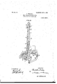
- Figure 1 is a front view.
- Fig. 2 is a side "iew, partly in section, of my improvement applied to a loom.
- Figs. 2 and 2 are details of the same.
- Fig. 3 1s a transverse section showing the weft-fork with an accompanying detail plan of one of the parts thereof.
- Fig. 4 shows the shuttle-peg.
- Fig. 5 shows the shuttle drawn to an enlarged scale
- Fig. 6 shows the device in action.
- Said magazine consists of a flat L-shaped bar, with a central slot therein, as 0, extending the full length and along the base of the bar, which projects toward the slay.
- the lower portion 0 0f the base below the slot is a little shorter than the upper portion c which is bent over at the end, a narrow opening being left between said bent-over end and the end of the shorter portion.
- the shuttle peg or skewer e, on which the cop is placed, is separate from the shuttle and is formed at its base, preferabl v,with two rings or collars e, having a space between them corre- 6c sponding to the thickness of the aforesaid L- sha ped bar forming the magazine 0, in which t-heyare placed, resting on each other and parallel to the shuttle-race.
- - T he shuttle-pegs, with the cops thereon, are placed in the magazine by passing one of the rings e through the enlarged portion 0 of the slot 0 and allowing them to slide down the slot 0 with the inner edges of the plate 0 in the grooves e of the shuttle-peg until the magazine is full or the required number placed therein, the collars on the bottom peg resting on the projection d.
- the length of the horizontal slot in the base. of the magazine is suflicient for retaining three (preferably) or other convenient number of shuttle-pegs with cops thereon when in the position shown in Fig.2.
- the shuttle-peg and cop at the mouth of the horizontal slot is prevented from falling out by the free end 0 of a spring 0 Fig. 2, pressing against the collars e of the shuttle-peg until the peg is forced out by the action hereinafter described, of the projection (Z.
- the ends of the threads from the cops in the magazine are retained until the cop is placed in the shuttle by being passed round the rod and wound spirally on the vertical rod fixed on the breashheam. (See Fig.
- a lever q is fixed near one end and a lever p fixed near the opposite end of a rod 9, hose ends are supported in brackets secured to the loom-frame below the breast-beam.
- the retaining device for holding the peg in the shuttle may be such as has been previously employed in automatic looms, consisting of two spring-cli s, as f ,which grip the rings or 001- lars e 0 the shuttle-peg and hold it in its place when with the cop it is lnserted in the shuttle.
- Adiagonal slit Fig. 5, is formed at the opposite end of the s iuttle f, so that when a cop is inserted in the shuttle the thread may pass to the hole or eye 1 through which the yarn is paid out.
- the weft-fork lever k causes the catch m, which is pivoted on the catch m on the up )er end of the lever 1), that is fitted on the ro g, to actuate, through said rod g, the lever h at the opposite end of the rod g and causes the lever h to engage with the lever u, thereby releasing the stud s, fixed to the lower portion of the magazine, said lower portion being then caused to swing toward the slay by the action of the spring t as far as is permitted by the projection u on the lever a, as shown in Fig. 6.
- the rod q is actuated by the fork-lever is through the lever p, the lever q, which is connected by the band u to the upper portion of the bracket u that is pivoted at its lower end on a stud 1, fixed to the slay m, pulls said u )per portion to one side, but parallel with the slay, and the bent end of said bracl-zet is then in position for engaging with the bent end (1 of the rod (1 if the shuttle does not box properly.
- the shuttle If the shuttle boxes properly, it tightens the check-strap f Said strap has an enlargement thereon which when the strap tightens engages with the staple n fixed .to the bracket u", and moves said bracket back to a vertical position, so that it will miss the aforesaid bent end (1. If the shuttle does not box properly, the check-strap is not tightened, and the bent end cl en a es with the rod '1 which passes through aliole in the bracket (1 causing said rod to slide toward and engage with.
- Apparatus for automatically replenishing the weft in loom-shuttles comprising a bracket, a magazine for containing cops, consisting of an L-shaped frame suspended from said bracket, said magazine adapted to swing from its point of suspension toward the slay,
- a magazine for automatic weft-replenishing looms comprising a swinging L-shape slotted bar supporting a number of cops and feed means for forcing the cop at the bottom of the slotted bar from the magazine as it swings, into a shuttle, upon the failure of 'a cop therein.
- a magazine for automatic weft-repleni ishing looms comprising a slotted L-shaped pivoted frame, a projection (Z in the path of said slot in the lower leg of the L-shaped frame, and means for oscillating said frame upon the failure of the weft, in combination with the slay and shuttle and means to bring the shuttle beneath the open end of the slot ted frame and toengage said frame to move it against said projection, whereby a spindle with a cop thereon will be forced from the frame into the shuttle.
Landscapes
- Engineering & Computer Science (AREA)
- Textile Engineering (AREA)
- Looms (AREA)
Description
No. 809,158. I PATENTED JAN. 2, 1906.
- 0. WHALLBY.
WBPT REPLBNISHING LOOM.
APPLICATION FILED JUL! 21. 1903.
a BHEnrH-SKBM' 1.
FiCJ
INVEA foR UNITED STATES,
PATENT} OFFICE.
Specification of Letters Patent.
Patented Jan. 2, 1806.
Application filed July 21, 1903. Serial No- 166,424.
To all whom it may concern/.-
Be it known that I, CHRISTOPHER WHAL- LE1, a subject of the King of Great Britain and Irelandn'esiding at Va terloo Mill, Clitheroe, in the county of Lancaster, Englandhave invented new and useful Improvements in Automatic W'eft-Replenishin Loomsfor eaving, of which the following is a specification.
The improvement which forms the subject of this invention relates to mechanism that may be fitted to existing looms in order that when a cop fails or gives out a perfect cop can be automatically placed in the shuttle and the shuttle-peg which has held the previously-used cop or with a partially-used cop, if the thread be broken, removed from the shuttle without stopping the loom.
In the accompanying drawings, Figure 1 is a front view. Fig. 2 is a side "iew, partly in section, of my improvement applied to a loom. Figs. 2 and 2 are details of the same. Fig. 3 1s a transverse section showing the weft-fork with an accompanying detail plan of one of the parts thereof. Fig. 4 shows the shuttle-peg. Fig. 5 shows the shuttle drawn to an enlarged scale, and Fig. 6 shows the device in action.
In the views the same letters refer to like parts.
According to and for the urpose of this invention I sus end a 1118 1121116 0 bv its up- )er end from a racketb, fixed to the breast eam a,preferably on the oil side of the loomviz., the side that is opposite to the side on which the strap-fork is placed. Said magazine consists of a flat L-shaped bar, with a central slot therein, as 0, extending the full length and along the base of the bar, which projects toward the slay. The lower portion 0 0f the base below the slot is a little shorter than the upper portion c which is bent over at the end, a narrow opening being left between said bent-over end and the end of the shorter portion. When the magazine is at rest, the bottom of the vertical portion of the slot 0 is covered or closed by ahorizontal projection (1, supported by a bracket d fixed on the breastbeam, (see Fig. 2,) and the shuttle-pegs 2, with the cops thereon, that are placed in the vertical slot 0 in the magazine rest on said projection; but when the magazine is caused to swing toward the shuttle-race out of the way of the projection h in the manner hereinafter described an uninterrupted passage exists from the slot in the vertical portion to the slot in the base of the magazine, as in Fig. 6.
The shuttle peg or skewer e, on which the cop is placed, is separate from the shuttle and is formed at its base, preferabl v,with two rings or collars e, having a space between them corre- 6c sponding to the thickness of the aforesaid L- sha ped bar forming the magazine 0, in which t-heyare placed, resting on each other and parallel to the shuttle-race.- T he shuttle-pegs, with the cops thereon, are placed in the magazine by passing one of the rings e through the enlarged portion 0 of the slot 0 and allowing them to slide down the slot 0 with the inner edges of the plate 0 in the grooves e of the shuttle-peg until the magazine is full or the required number placed therein, the collars on the bottom peg resting on the projection d. The length of the horizontal slot in the base. of the magazine is suflicient for retaining three (preferably) or other convenient number of shuttle-pegs with cops thereon when in the position shown in Fig.2. The shuttle-peg and cop at the mouth of the horizontal slot is prevented from falling out by the free end 0 of a spring 0 Fig. 2, pressing against the collars e of the shuttle-peg until the peg is forced out by the action hereinafter described, of the projection (Z. The ends of the threads from the cops in the magazine are retained until the cop is placed in the shuttle by being passed round the rod and wound spirally on the vertical rod fixed on the breashheam. (See Fig. 1.) A lever q is fixed near one end and a lever p fixed near the opposite end of a rod 9, hose ends are supported in brackets secured to the loom-frame below the breast-beam. The retaining device for holding the peg in the shuttle may be such as has been previously employed in automatic looms, consisting of two spring-cli s, as f ,which grip the rings or 001- lars e 0 the shuttle-peg and hold it in its place when with the cop it is lnserted in the shuttle. Adiagonal slit ,Fig. 5, is formed at the opposite end of the s iuttle f, so that when a cop is inserted in the shuttle the thread may pass to the hole or eye 1 through which the yarn is paid out.
In working the shuttle follows the ordinary course. When the weft fails or gives out, the weft-fork lever k, Figs. 1 and 3, causes the catch m, which is pivoted on the catch m on the up )er end of the lever 1), that is fitted on the ro g, to actuate, through said rod g, the lever h at the opposite end of the rod g and causes the lever h to engage with the lever u, thereby releasing the stud s, fixed to the lower portion of the magazine, said lower portion being then caused to swing toward the slay by the action of the spring t as far as is permitted by the projection u on the lever a, as shown in Fig. 6. The co that is at the bottom of the vertical slot wi 1 then fall into the horizontal slot at the rear of the cops previouslyin said horizontal slot. As the slay moves toward the cloth the projection u pivotally secured to the slay, will engage with the stop 0, attached to the magazine, and push the magazine back to its normal position; but as there isnow one more cop in the horizontal slot than previously the-one at the open end 0 of said slot is pressed out by the projection d remaining immovable by the spring d engaging with a notch (1 Fig. 2", in the spindle d of said projection and is pressed into the shuttle, which at that instant is immediately under the mouth or delivery end 0 of the magazine, said cop taking the place of the empty peg in said shuttle, the em ty peg falling through an aperture or vertical. slot y in the shuttle-race into a skip or other receptacleplaced beneath to receive it. If the loom is required to run as an ordinary loom, the catch m on the weft-fork lever is turned over and out of action, the magazine being then inoperative. \Vhen the rod q is actuated by the fork-lever is through the lever p, the lever q, which is connected by the band u to the upper portion of the bracket u that is pivoted at its lower end on a stud 1, fixed to the slay m, pulls said u )per portion to one side, but parallel with the slay, and the bent end of said bracl-zet is then in position for engaging with the bent end (1 of the rod (1 if the shuttle does not box properly. If the shuttle boxes properly, it tightens the check-strap f Said strap has an enlargement thereon which when the strap tightens engages with the staple n fixed .to the bracket u", and moves said bracket back to a vertical position, so that it will miss the aforesaid bent end (1. If the shuttle does not box properly, the check-strap is not tightened, and the bent end cl en a es with the rod '1 which passes through aliole in the bracket (1 causing said rod to slide toward and engage with. the lever h and press it farther back than is effected at the period when the stud s is released, as hereinbefore described, so that the lever p will move the fork-lever 7c sufficiently to release the loomhandle k from a catch on the loom-frame and stop the loom. At the same time the rod d moving along under the flat spring d, raises said spring out of the groove (i out in the spindle d of the projection 11, and allows said spindle to move back in the bracketd The spindle d 6o thereby preventing the leading peg from be- 7 1. Apparatus for automatically replenishing the weft in loom-shuttles, comprising a bracket, a magazine for containing cops, consisting of an L-shaped frame suspended from said bracket, said magazine adapted to swing from its point of suspension toward the slay,
and means adapted to force a cop into the shuttle from the mouth of said magazine as it swings from said slay.
2. A magazine for automatic weft-replenishing looms, comprising a swinging L-shape slotted bar supporting a number of cops and feed means for forcing the cop at the bottom of the slotted bar from the magazine as it swings, into a shuttle, upon the failure of 'a cop therein.
3. A magazine for automatic weft-repleni ishing looms, comprising a slotted L-shaped pivoted frame, a projection (Z in the path of said slot in the lower leg of the L-shaped frame, and means for oscillating said frame upon the failure of the weft, in combination with the slay and shuttle and means to bring the shuttle beneath the open end of the slot ted frame and toengage said frame to move it against said projection, whereby a spindle with a cop thereon will be forced from the frame into the shuttle.
In testimony whereof I have signed my name to this specification in the presence of two subscribing witnesses.
CHRISTOPHER WHALLEY.
Witnesses:
THOS. P. PREsoo'r'r, J. ERNEST HUGHES.
Priority Applications (1)
| Application Number | Priority Date | Filing Date | Title |
|---|---|---|---|
| US16642403A US809158A (en) | 1903-07-21 | 1903-07-21 | Weft-replenishing loom. |
Applications Claiming Priority (1)
| Application Number | Priority Date | Filing Date | Title |
|---|---|---|---|
| US16642403A US809158A (en) | 1903-07-21 | 1903-07-21 | Weft-replenishing loom. |
Publications (1)
| Publication Number | Publication Date |
|---|---|
| US809158A true US809158A (en) | 1906-01-02 |
Family
ID=2877639
Family Applications (1)
| Application Number | Title | Priority Date | Filing Date |
|---|---|---|---|
| US16642403A Expired - Lifetime US809158A (en) | 1903-07-21 | 1903-07-21 | Weft-replenishing loom. |
Country Status (1)
| Country | Link |
|---|---|
| US (1) | US809158A (en) |
-
1903
- 1903-07-21 US US16642403A patent/US809158A/en not_active Expired - Lifetime
Similar Documents
| Publication | Publication Date | Title |
|---|---|---|
| US809158A (en) | Weft-replenishing loom. | |
| US560181A (en) | Elizabeth howard administratrix of said tom howard | |
| US1727315A (en) | Thread positioner for filling replenishing looms | |
| US246637A (en) | Loom-shuttle | |
| US635198A (en) | Apparatus for weaving fabrics. | |
| US596487A (en) | George | |
| US1285386A (en) | Filling-end-retaining means for weft-replenishing looms. | |
| US1836965A (en) | Shuttle | |
| US2620833A (en) | Reserve bobbin magazine for looms | |
| US744442A (en) | Loom. | |
| US920037A (en) | Automatic filling-replenishing feeler-loom. | |
| US64573A (en) | Improvement in looms | |
| US1123192A (en) | Filling-positioning device for looms. | |
| US2148597A (en) | Loom shuttle feeler | |
| US710767A (en) | Weft stop-motion for looms. | |
| US866051A (en) | Thread clearing and parting mechanism for weft-replenishing looms. | |
| US454797A (en) | draper | |
| US697004A (en) | Filling-replenishing loom. | |
| US1766850A (en) | Thread holder for weft-replenishing looms | |
| US498194A (en) | Warp stop-motion for looms | |
| US527014A (en) | draper | |
| US567351A (en) | mckay | |
| US560745A (en) | James h | |
| US577441A (en) | James e | |
| US1283587A (en) | Automatic filling-replenishing loom. |