US80909A - Lithographer - Google Patents
Lithographer Download PDFInfo
- Publication number
- US80909A US80909A US80909DA US80909A US 80909 A US80909 A US 80909A US 80909D A US80909D A US 80909DA US 80909 A US80909 A US 80909A
- Authority
- US
- United States
- Prior art keywords
- deflector
- chimney
- standards
- air
- springs
- Prior art date
- Legal status (The legal status is an assumption and is not a legal conclusion. Google has not performed a legal analysis and makes no representation as to the accuracy of the status listed.)
- Expired - Lifetime
Links
- 239000002184 metal Substances 0.000 description 6
- QVGXLLKOCUKJST-UHFFFAOYSA-N atomic oxygen Chemical compound [O] QVGXLLKOCUKJST-UHFFFAOYSA-N 0.000 description 1
- 230000015572 biosynthetic process Effects 0.000 description 1
- 238000010276 construction Methods 0.000 description 1
- 230000007547 defect Effects 0.000 description 1
- 230000000694 effects Effects 0.000 description 1
- 239000010437 gem Substances 0.000 description 1
- 238000000034 method Methods 0.000 description 1
- 229910052760 oxygen Inorganic materials 0.000 description 1
- 239000001301 oxygen Substances 0.000 description 1
- 230000002093 peripheral effect Effects 0.000 description 1
- 230000000284 resting effect Effects 0.000 description 1
- 230000002459 sustained effect Effects 0.000 description 1
Images
Classifications
-
- F—MECHANICAL ENGINEERING; LIGHTING; HEATING; WEAPONS; BLASTING
- F21—LIGHTING
- F21V—FUNCTIONAL FEATURES OR DETAILS OF LIGHTING DEVICES OR SYSTEMS THEREOF; STRUCTURAL COMBINATIONS OF LIGHTING DEVICES WITH OTHER ARTICLES, NOT OTHERWISE PROVIDED FOR
- F21V17/00—Fastening of component parts of lighting devices, e.g. shades, globes, refractors, reflectors, filters, screens, grids or protective cages
Definitions
- ILFETERS PNOIQUTMOGRAPMER
- WASHANGTON D. c.
- My invention relates to that class of burners in which the chimney, resting upon a seat formed below the elevated deflector, is sustained inposition by means of springs bearing outwardly, against its inner surface, and it has reference principally to themethodof supporting the deflector in its elevated position, and of forming the chimney-holding springs.
- the improvemcntsnvhich are made the subject of this patent may be stated to consist First, in connecting the elevated deflector to the air-distributor or chimney-rest by means of standards extending from the periphery of the deflector to the periphery, or thereabouts, of the air-distributor.
- standards extending from the periphery of the deflector to the periphery, or thereabouts, of the air-distributor.
- This ring may be either for-medonone piece with the standards/or it may be a separate piccc'bent over so as to embrace both the edge of the air-distribnter and a flange or holding-piece formed with the standards.
- the burner shown in illustration of my invention is onc in which the upper section, consisting of the deflector A, chimney-holding-springsa, standards I), and'air-distributer or chimney-rcst B, is supported by means of the sleeve G upon the lower section, composed of-thc base, D, wick-tube c, and wick-adjusting devices at.
- the sleeve 0 fits upon the wick-tube, and its sides are so formed as to leave between them and each side of the wick-tube, passage through which air-is fed directly tothc ignited wick.
- the lower and expanded end of. the sleeve fits over the ooyered base of thb burner, and in ordcr'to obtain the necessary supply of air, as just indicated, a series of holes or perforations is formed in the sleeve, below the point where the air-distributor is attached, and above the point where the sleeve rests upon the basg.
- the deflector A is held inposition by rncans,of the standards 6, which extend from its periphery 'to or near the periphery of the airdistributcrB.
- the springs are formed by detaching or separating the lower end of every other standard from the ring 0,
- the'ring c is swaged or bent over and around the rim of the distributor, as shown in fig. 1, constituting not only the means for uniting said parts, but also the rest or seat for the chimney.
- the ring a need not be in one piece with the standards, for the latter may be provided with a flange extending entirely arou'nd and connecting them togethciywhich flange can be held to the distributer by means of a separate annulus, bent over both the flange and the rim of the distributer-plat-e, or other means which will readily suggest themselves can be employed for the purpose.
- the method above described of connecting the deflector and air-distributor by means of standards extending from the periphery of the one to or near that of the other, and of forming the springs and standards, and of attaching themto the air-distributor, is productive of many advantages.
- the deflector is held firmly in positionfa nd will always be maintained in its proper relation to the wick-tube, while, by striking up all the parts, with the exceptionof the air-distributor, from one piece of metal, a great saving of labor and expense is elfected, and a neater article is produced thanhas heretofore been-practicable.
- the springs a are so formed and combined with the other parts of the burner that the chimney cannot tip over, thus remedying a great defect in burners of this class.
- Each spring is formed as shown in section ate in fig. 1, slightly bulging in the centre, and with its greatest springiness at its end or lowest point.
- Each spring extends from the periphery of the deflector to, or almost to, the chimney-seat or rest, in a nearly vertical direction, projecting just far enough, as shown in the drawings, to cause the chimney, when placed in its seat, to compress it slightly, leaving a small space between the periphery of the deflector and the chimney for the passage of air.
- the chimney tends to tip, it will bear against the bulging or least elastic portion of the nearly vertical spring-arm, and if this 'pressureof the chimney be increased, thelower end of the spring will be forced against shoulderK on the air-distributor, which prevents the further yielding of the spring, and consequently the further tilting of the chimney. It is in fact impossible, even without the shoulder K, for thechimney to be tipped overiby accident, and any attempt to separate it from the-burner by tilting it can only result in its breaking.
Landscapes
- Engineering & Computer Science (AREA)
- General Engineering & Computer Science (AREA)
- Wick-Type Burners And Burners With Porous Materials (AREA)
Description
w. CARLETON.
Lamp-Chimney Holder.
No. 80,909. I t Patented Aug. II, 1868.
E vlllll'..
ILFETERS, PNOIQUTMOGRAPMER, WASHANGTON, D. c.
Quite? gems intent @ffire.
WILLIAM GARLETON, 0F BOSTON, MASSACHUSETTS.
' Letters Patent No. 80,909, dated August 11, 1868.
IMPROVEMENT IN LAMP-BURNERS.
TO WHOM IT MAY CONCERN:
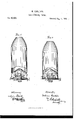
Be it known that LdVILLIAhi GARLETON, of Boston, in the county of Suffolk, and State of Massachusetts, have invented certain new and useful Improvements in Lamp-Burners; and I hereby declare the following to be a full, clear, and exact description of the same, reference being bad to the accompanying drawings, in which- Figure 1 represents a vertical central section, and
Figure 2 anclevation of my improved burner.
My invention relates to that class of burners in which the chimney, resting upon a seat formed below the elevated deflector, is sustained inposition by means of springs bearing outwardly, against its inner surface, and it has reference principally to themethodof supporting the deflector in its elevated position, and of forming the chimney-holding springs. V
The improvemcntsnvhich are made the subject of this patent may be stated to consist First, in connecting the elevated deflector to the air-distributor or chimney-rest by means of standards extending from the periphery of the deflector to the periphery, or thereabouts, of the air-distributor. By this means I am enabled to form the deflector and standards, or deflector, standards, and chimney-holding springs from one continuous piece of sheet metal. a
Second, in attaching the standards, springs, and deflector to the air-distributer or chimney-rest by means of a ring bent over and around the outer edge or periphery of, the air-distributor. This ring may be either for-medonone piece with the standards/or it may be a separate piccc'bent over so as to embrace both the edge of the air-distribnter and a flange or holding-piece formed with the standards.
Third, in the hereinafter-described formation of the springs, and their combination with the air-distributor,
so as to prevent the tipping of the chimney. I
Fourth, in the alternate arrangement of the standards and chimney-holding spring, and in other minor features relating to thc same, which need not now be specified. I
Fifth, in the construction and combination, with the other parts of the burner, of the sleeve which fits upon the neck-tube and over the base, and holds'thc deflector and air-distributor in position,
To enable those skilled in the art to understand and use my invention, I will procecdto describe the manner in which the same is or may be carriedinto cfi'ect, by reference to the accompanying drawings.
The burner shown in illustration of my invention is onc in which the upper section, consisting of the deflector A, chimney-holding-springsa, standards I), and'air-distributer or chimney-rcst B, is supported by means of the sleeve G upon the lower section, composed of-thc base, D, wick-tube c, and wick-adjusting devices at.
The sleeve 0 fits upon the wick-tube, and its sides are so formed as to leave between them and each side of the wick-tube, passage through which air-is fed directly tothc ignited wick.
The lower and expanded end of. the sleeve fits over the ooyered base of thb burner, and in ordcr'to obtain the necessary supply of air, as just indicated, a series of holes or perforations is formed in the sleeve, below the point where the air-distributor is attached, and above the point where the sleeve rests upon the basg.
Through these holes the air passes up between the wick-tube andsleeve to the ignited wick, and, supplying the flame with oxygen, pcrccptibly increases its brilliancy. I
The deflector Ais held inposition by rncans,of the standards 6, which extend from its periphery 'to or near the periphery of the airdistributcrB. v
In order both to lessen the number of operations required to complete the standards and deflector, and to produce a more perfect and at the same time less expensive burner than would otherwise be practicable, I strike up the deflector and standards from one continuous sheet-of metal, and for a like reason I formthe chimneyholding springs in the samemanncr. p
The metal from which these parts are made'is struck up so "as to form the deflector, the outer portion being bent down at about right angles to the deflector, and cut out-so as toi remov e the metal between the standards, leaving at the lower end a continuous ring or annulus, e, which connects the standards.
The springs are formed by detaching or separating the lower end of every other standard from the ring 0,
as shown-at a, and the strip thus freed is bent so as to form a spring, as shown in fig. 1, its greatest springiness being at its end or lowest point, for the purpose hereinafter referred to.
It will be seen that the springs and standards are thus. arranged upon the periphery of the deflector'in alternate order.
In securing the deflector, with its springs and standards, to'the air-distributor, the'ring c is swaged or bent over and around the rim of the distributor, as shown in fig. 1, constituting not only the means for uniting said parts, but also the rest or seat for the chimney.
The ring a need not be in one piece with the standards, for the latter may be provided with a flange extending entirely arou'nd and connecting them togethciywhich flange can be held to the distributer by means of a separate annulus, bent over both the flange and the rim of the distributer-plat-e, or other means which will readily suggest themselves can be employed for the purpose. p
The method above described of connecting the deflector and air-distributor by means of standards extending from the periphery of the one to or near that of the other, and of forming the springs and standards, and of attaching themto the air-distributor, is productive of many advantages. The deflector is held firmly in positionfa nd will always be maintained in its proper relation to the wick-tube, while, by striking up all the parts, with the exceptionof the air-distributor, from one piece of metal, a great saving of labor and expense is elfected, and a neater article is produced thanhas heretofore been-practicable.
The springs a are so formed and combined with the other parts of the burner that the chimney cannot tip over, thus remedying a great defect in burners of this class. Each springis formed as shown in section ate in fig. 1, slightly bulging in the centre, and with its greatest springiness at its end or lowest point.
Each spring extends from the periphery of the deflector to, or almost to, the chimney-seat or rest, in a nearly vertical direction, projecting just far enough, as shown in the drawings, to cause the chimney, when placed in its seat, to compress it slightly, leaving a small space between the periphery of the deflector and the chimney for the passage of air. Thus, when the chimney tends to tip, it will bear against the bulging or least elastic portion of the nearly vertical spring-arm, and if this 'pressureof the chimney be increased, thelower end of the spring will be forced against shoulderK on the air-distributor, which prevents the further yielding of the spring, and consequently the further tilting of the chimney. It is in fact impossible, even without the shoulder K, for thechimney to be tipped overiby accident, and any attempt to separate it from the-burner by tilting it can only result in its breaking.
Having now described my invention, and the manner in which the same is or may becarried into effect, what I claim, and desire to secure by Letters Patent, is i 1. Forming the elevated deflector and the supporting-standards upon its periphery in one continuous piece of metal, substantially as and for the purposes set forth.
2-. Forming the elevated deflector, its supporting-standards, and the chimney holding springs in one continuous piece, substantially as herein shown and set forth.
8. The arrangement of the standards and chimney-supporting springs in alternate order upon the periphery of the deflector, in the manner shown and described,
4. The combination, with the air-distributer and the elevated deflector, with its chimney-holding springs and standards, of a bent-over ring for-holding the deflector to the, air-distributor, whether the said ring be formed in' one piece with said standards, or separately therefrom, as and for the purposes set forth.
5. The combination of the elevated deflector and its downwardly-extending peripheral springs with the chimney and chimney-seat, and shoulder formed on said seat or the -air-distributer, to prevent the excessive yielding of said springs, as herein shown and set forth.
6. The combination, with the base andwick-tube, of a sleeve for supporting the deflector and air-distribute! held up on the base and wick-tube, in the manner described, and provided, near its lower end, with perforations or openings for the supply of air directly to the flame, as set forth.
In witness whereof, I have signed this specification in presence of two subscribing witnesses.
Y WM. CARLETON.
Witnesses:
A. PoLLoK, E. E. GADNE.
Publications (1)
| Publication Number | Publication Date |
|---|---|
| US80909A true US80909A (en) | 1868-08-11 |
Family
ID=2150404
Family Applications (1)
| Application Number | Title | Priority Date | Filing Date |
|---|---|---|---|
| US80909D Expired - Lifetime US80909A (en) | Lithographer |
Country Status (1)
| Country | Link |
|---|---|
| US (1) | US80909A (en) |
Cited By (2)
| Publication number | Priority date | Publication date | Assignee | Title |
|---|---|---|---|---|
| US20080013997A1 (en) * | 2005-03-17 | 2008-01-17 | Kabushiki Kaisha Toshiba | Heating apparatus, heating apparatus control method and noncontact thermal sensing device |
| US20090207977A1 (en) * | 2008-02-15 | 2009-08-20 | Xiaodong Wu | Laser Aligned Image Guided Radiation Beam Verification Apparatus |
-
0
- US US80909D patent/US80909A/en not_active Expired - Lifetime
Cited By (2)
| Publication number | Priority date | Publication date | Assignee | Title |
|---|---|---|---|---|
| US20080013997A1 (en) * | 2005-03-17 | 2008-01-17 | Kabushiki Kaisha Toshiba | Heating apparatus, heating apparatus control method and noncontact thermal sensing device |
| US20090207977A1 (en) * | 2008-02-15 | 2009-08-20 | Xiaodong Wu | Laser Aligned Image Guided Radiation Beam Verification Apparatus |
Similar Documents
| Publication | Publication Date | Title |
|---|---|---|
| US80909A (en) | Lithographer | |
| US125672A (en) | Improvement in lamp-burners | |
| US1246522A (en) | Burner. | |
| US399807A (en) | Tubular lantern | |
| US93087A (en) | Improvement in lamp-burners | |
| USRE3158E (en) | James donning | |
| US585817A (en) | qordon | |
| US1082284A (en) | Air-distributer for central-draft lamps. | |
| US1010275A (en) | Inverted incandescent gas-lamp. | |
| US421171A (en) | Joseph jauch | |
| US82480A (en) | Edward | |
| US412958A (en) | Joseph jaitch | |
| US103598A (en) | Improvement in lamp-burners | |
| US79488A (en) | Improvement in lamp-bubnees | |
| US93661A (en) | Improvement in vapor-burners | |
| US103628A (en) | Lemuel w | |
| US60215A (en) | marcy | |
| US931642A (en) | Lamp-burner. | |
| US40226A (en) | Improvement in lamps | |
| US79369A (en) | mason | |
| US442669A (en) | George w | |
| US383338A (en) | Argand gas-burner | |
| US85697A (en) | Improvement in lamp-burners | |
| US688496A (en) | Tubular lantern. | |
| US586061A (en) | Frank rhind |