US809062A - Door check or fastener. - Google Patents
Door check or fastener. Download PDFInfo
- Publication number
- US809062A US809062A US1905253598A US809062A US 809062 A US809062 A US 809062A US 1905253598 A US1905253598 A US 1905253598A US 809062 A US809062 A US 809062A
- Authority
- US
- United States
- Prior art keywords
- plunger
- rod
- casing
- door
- fastener
- Prior art date
- Legal status (The legal status is an assumption and is not a legal conclusion. Google has not performed a legal analysis and makes no representation as to the accuracy of the status listed.)
- Expired - Lifetime
Links
- 238000010276 construction Methods 0.000 description 3
- 239000013013 elastic material Substances 0.000 description 1
- 239000002184 metal Substances 0.000 description 1
- 230000001105 regulatory effect Effects 0.000 description 1
Images
Classifications
-
- E—FIXED CONSTRUCTIONS
- E05—LOCKS; KEYS; WINDOW OR DOOR FITTINGS; SAFES
- E05B—LOCKS; ACCESSORIES THEREFOR; HANDCUFFS
- E05B63/00—Locks or fastenings with special structural characteristics
- E05B63/18—Locks or fastenings with special structural characteristics with arrangements independent of the locking mechanism for retaining the bolt or latch in the retracted position
- E05B63/20—Locks or fastenings with special structural characteristics with arrangements independent of the locking mechanism for retaining the bolt or latch in the retracted position released automatically when the wing is closed
-
- Y—GENERAL TAGGING OF NEW TECHNOLOGICAL DEVELOPMENTS; GENERAL TAGGING OF CROSS-SECTIONAL TECHNOLOGIES SPANNING OVER SEVERAL SECTIONS OF THE IPC; TECHNICAL SUBJECTS COVERED BY FORMER USPC CROSS-REFERENCE ART COLLECTIONS [XRACs] AND DIGESTS
- Y10—TECHNICAL SUBJECTS COVERED BY FORMER USPC
- Y10T—TECHNICAL SUBJECTS COVERED BY FORMER US CLASSIFICATION
- Y10T292/00—Closure fasteners
- Y10T292/08—Bolts
- Y10T292/096—Sliding
- Y10T292/0999—Spring retracted
- Y10T292/1003—Swinging catch
Definitions
- This invention relates to improvements in door checks or fasteners.
- the object of the invention is to provide a device of this character by which a door may be securely held open at different positions or locked in closed position.
- a further object is to provide a device of this character which will be simple, strong, and durable in construction, eflicient in use, and well adapted to the purpose for which it is designed.
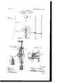
- Figure 1 is a side view of the lower portion of a door
- Fig. 2 is a vertical longitudinal sectional view through the fastener.
- Fig. 3 is a horizontal sectional view through the same, taken on the line 3 3 of Fig. 2; and
- Fig. 4 is a detail sectional view of the lower portion of the plunger-rod, showing the reduced shoe-holding end of the same separable or removably connected to the main body of the plunger-rod.
- 1 denotes the check, which consists of a casing 2, adapted to be screwed or otherwise secured to the inner side of a door adjacent to the lower edge of the same.
- a plunger-rod 3 on the upper end of which is arranged a foot-piece 4, and on the lower end of the same is formed an annular flange or collar 5, below which said plunger-rod is reduced in size and provided with a head or enlargement 6.
- a shoe 7 On the reduced end of the plunger-rod is placed a shoe 7, which is preferably formed of rubber or other elastic material.
- an aperture or slot 10 In the outer side of the casing, adjacent to the upper end of the same, is formed an aperture or slot 10, on each side of which are formed outwardly projecting apertured flanges 12. Between said flanges 12 is pivotally mounted a releasing-lever 13, the upper end of said lever being pivotally connected to the pawl or dog 9 by means of a link 14. On the lower end of the lever 13 is formed a head or enlargement which is adapted to be engaged by the foot and by which said lever is operated to release the pawl or dog from the ratchet-teeth 8 on the plunger-rod.
- a flat spring 15 Secured to the outer face of the casing, between the same and the lower end of the releasing-lever 13, is secured a flat spring 15, the free end of which is adapted to bear under the head of the releasing-lever to normally force the same outwardly and upwardly, which will prevent the pawl or dog 9 from becoming disengaged from the ratchet-teeth on the plunger-rod untilthe releasing-lever is pressed inwardly or downwardly against the tension of said spring.
- a collar 16 On the plunger-rod 3 within the casing 2 is arranged a collar 16, said collar being adjustably secured to the rod by means of a setscrew 17. Between said collar and the lower end of the casing 2 is arranged a coil-spring 18, the tendency of which is to force the plunger-rod upwardly in the casing 1, thus disengaging the shoe 7 on the lower end of the same from the floor.
- Fig. 4 of the drawings the head 6 and the reduced lower end of the plunger-rod are removably attached to the main body of the rod by providing said reduced portion with a screw-threaded upper end 19 to be screwed into a threaded socket 20, formed in thelower end of the plunger-rod, as shown.
- the rubber shoe when worn maybereadily detached from the check and replaced by another or by an all-metal shoe or bolt to engage a socket or keeper in the threshold or floor, thus forming a regular fastener.
- the plunger-rod 3 In operation when it is desired to lock the door to which the device is applied the plunger-rod 3 is forced downwardly, thus engaging the shoe on the lower end of the same with the floor, in which position the rod is held by means of the pawl-and-ratchet connection between said plunger-rod and the casing, thus enabling the door to be secured at any desired position.
- the herein-described door-check comprislng a casing, a plunger-bar mounted to slide in said casing and provided with a series of ratchet-teeth on one side thereof, a pawl pivoted within the casing and designed to en gage the teeth on the plunger to hold said plunger in projected position, a pivotally mounted foot-lever connected to said pawl by a link, a spring secured to the casing and hearing at its free end against said foot-lever to hold the pawl in engagement with the teeth on the plunger, a spring surrounding the plunger within the casing, an adjustable ring on the plunger for regulating the tension of the spring, an elastic shoe upon the lower end of the plunger and a foot-piece on the upper end of said plunger, all substantially as described.
Landscapes
- Engineering & Computer Science (AREA)
- Structural Engineering (AREA)
- Devices For Conveying Motion By Means Of Endless Flexible Members (AREA)
Description
" No. 809,062. PATBNTED JAN. 2, 1906. 0. N. P. ING-ALLS.
DOOR CHECK OR PASTENER.
APPLICATION FILED APR.3, 1905.
CHARLES N. P. INGALLS, OF LYNN, MASSACHUSETTS.
DOOR CHECK 0R" FASTENER.
Specification of Letters Patent.
Patented Jan. 2, 1906.
Application filed April 3, 1905. Serial No. 253,598-
1'0 all whom it may concern:
Be it known that I, CHARLES N. P. INGALLS, a citizen of the United States, residing at Lynn, in the county of Essex and State of Massachusetts, have invented certain new and useful Improvements in Door Checks or Fasteners; and I do declare the following to be a full, clear, and exact description of the invention, such as will enable others skilled in the art to which it appertains to make and use the same.
This invention relates to improvements in door checks or fasteners.
The object of the invention is to provide a device of this character by which a door may be securely held open at different positions or locked in closed position.
A further object is to provide a device of this character which will be simple, strong, and durable in construction, eflicient in use, and well adapted to the purpose for which it is designed.
With these and other objects in view the invention consists of certain novel features of construction, combination, and arrangement of parts, as will be hereinafter described and claimed.
In the accompanying drawings, Figure 1 is a side view of the lower portion of a door,
showing the application of the invention. Fig. 2 is a vertical longitudinal sectional view through the fastener. Fig. 3 is a horizontal sectional view through the same, taken on the line 3 3 of Fig. 2; and Fig. 4 is a detail sectional view of the lower portion of the plunger-rod, showing the reduced shoe-holding end of the same separable or removably connected to the main body of the plunger-rod.
Referring more particularly to the drawings, 1 denotes the check, which consists of a casing 2, adapted to be screwed or otherwise secured to the inner side of a door adjacent to the lower edge of the same. In the casing 2 is slidably mounted a plunger-rod 3, on the upper end of which is arranged a foot-piece 4, and on the lower end of the same is formed an annular flange or collar 5, below which said plunger-rod is reduced in size and provided with a head or enlargement 6. On the reduced end of the plunger-rod is placed a shoe 7, which is preferably formed of rubber or other elastic material. In the outer face of the plunger-rod 3 is formed a series of ratchet, teeth 8, with which is adapted to be engaged a pawl or dog 9, said pawl being pivotally mounted in the upper end of the casing -1, as shown.
In the outer side of the casing, adjacent to the upper end of the same, is formed an aperture or slot 10, on each side of which are formed outwardly projecting apertured flanges 12. Between said flanges 12 is pivotally mounted a releasing-lever 13, the upper end of said lever being pivotally connected to the pawl or dog 9 by means of a link 14. On the lower end of the lever 13 is formed a head or enlargement which is adapted to be engaged by the foot and by which said lever is operated to release the pawl or dog from the ratchet-teeth 8 on the plunger-rod. Secured to the outer face of the casing, between the same and the lower end of the releasing-lever 13, is secured a flat spring 15, the free end of which is adapted to bear under the head of the releasing-lever to normally force the same outwardly and upwardly, which will prevent the pawl or dog 9 from becoming disengaged from the ratchet-teeth on the plunger-rod untilthe releasing-lever is pressed inwardly or downwardly against the tension of said spring.
On the plunger-rod 3 within the casing 2 is arranged a collar 16, said collar being adjustably secured to the rod by means of a setscrew 17. Between said collar and the lower end of the casing 2 is arranged a coil-spring 18, the tendency of which is to force the plunger-rod upwardly in the casing 1, thus disengaging the shoe 7 on the lower end of the same from the floor.
In Fig. 4 of the drawings the head 6 and the reduced lower end of the plunger-rod are removably attached to the main body of the rod by providing said reduced portion with a screw-threaded upper end 19 to be screwed into a threaded socket 20, formed in thelower end of the plunger-rod, as shown. By constructing the device in this manner the rubber shoe when worn maybereadily detached from the check and replaced by another or by an all-metal shoe or bolt to engage a socket or keeper in the threshold or floor, thus forming a regular fastener.
In operation when it is desired to lock the door to which the device is applied the plunger-rod 3 is forced downwardly, thus engaging the shoe on the lower end of the same with the floor, in which position the rod is held by means of the pawl-and-ratchet connection between said plunger-rod and the casing, thus enabling the door to be secured at any desired position.
From the foregoing description, taken in connection with the accompanying drawings, the construction and operation of the invention will be readily understood without requiring a more extended explanation.
Having thus described my invention, what I claim as new, and desire to secure by Letters Patent, is
The herein-described door-check comprislng a casing, a plunger-bar mounted to slide in said casing and provided with a series of ratchet-teeth on one side thereof, a pawl pivoted within the casing and designed to en gage the teeth on the plunger to hold said plunger in projected position, a pivotally mounted foot-lever connected to said pawl by a link, a spring secured to the casing and hearing at its free end against said foot-lever to hold the pawl in engagement with the teeth on the plunger, a spring surrounding the plunger within the casing, an adjustable ring on the plunger for regulating the tension of the spring, an elastic shoe upon the lower end of the plunger and a foot-piece on the upper end of said plunger, all substantially as described.
In testimony whereof I have hereunto set my hand in presence of two subscribing witnesses.
' CHARLES N. P. INGALLS.
Witnesses:
EDWIN O. LEWIS,
MARION L. FILLING.
Priority Applications (1)
| Application Number | Priority Date | Filing Date | Title |
|---|---|---|---|
| US1905253598 US809062A (en) | 1905-04-03 | 1905-04-03 | Door check or fastener. |
Applications Claiming Priority (1)
| Application Number | Priority Date | Filing Date | Title |
|---|---|---|---|
| US1905253598 US809062A (en) | 1905-04-03 | 1905-04-03 | Door check or fastener. |
Publications (1)
| Publication Number | Publication Date |
|---|---|
| US809062A true US809062A (en) | 1906-01-02 |
Family
ID=2877543
Family Applications (1)
| Application Number | Title | Priority Date | Filing Date |
|---|---|---|---|
| US1905253598 Expired - Lifetime US809062A (en) | 1905-04-03 | 1905-04-03 | Door check or fastener. |
Country Status (1)
| Country | Link |
|---|---|
| US (1) | US809062A (en) |
Cited By (1)
| Publication number | Priority date | Publication date | Assignee | Title |
|---|---|---|---|---|
| US20200307762A1 (en) * | 2019-03-29 | 2020-10-01 | Airbus Operations Limited | Aircraft wing with wing tip device |
-
1905
- 1905-04-03 US US1905253598 patent/US809062A/en not_active Expired - Lifetime
Cited By (2)
| Publication number | Priority date | Publication date | Assignee | Title |
|---|---|---|---|---|
| US20200307762A1 (en) * | 2019-03-29 | 2020-10-01 | Airbus Operations Limited | Aircraft wing with wing tip device |
| US11613342B2 (en) * | 2019-03-29 | 2023-03-28 | Airbus Operations Limited | Aircraft wing with wing tip device |
Similar Documents
| Publication | Publication Date | Title |
|---|---|---|
| US653458A (en) | Sash-lock. | |
| US809062A (en) | Door check or fastener. | |
| US777408A (en) | Door stop or holder. | |
| US401003A (en) | Brake-handle | |
| US1534902A (en) | Doorcheck | |
| US308768A (en) | Door-stop | |
| US701586A (en) | Snap-hook. | |
| US688082A (en) | Door-check. | |
| US449916A (en) | Door-check | |
| US658122A (en) | Door-stop. | |
| US652001A (en) | Lock-hinge. | |
| US618818A (en) | William t | |
| US312859A (en) | Door-check | |
| US684586A (en) | Door-check. | |
| US490504A (en) | Door-check | |
| US360937A (en) | Door-check | |
| US49296A (en) | Door-bolt | |
| US1149809A (en) | Door-hasp. | |
| US559600A (en) | John d | |
| US490517A (en) | Latch | |
| US71828A (en) | George wells | |
| US1020322A (en) | Bench-screw. | |
| US443262A (en) | Door-check | |
| US776946A (en) | Door-holder. | |
| US988654A (en) | Hame-fastener. |