US809017A - Wardrobe-hook. - Google Patents
Wardrobe-hook. Download PDFInfo
- Publication number
- US809017A US809017A US24636505A US1905246365A US809017A US 809017 A US809017 A US 809017A US 24636505 A US24636505 A US 24636505A US 1905246365 A US1905246365 A US 1905246365A US 809017 A US809017 A US 809017A
- Authority
- US
- United States
- Prior art keywords
- hook
- rounded
- wardrobe
- garment
- supporting member
- Prior art date
- Legal status (The legal status is an assumption and is not a legal conclusion. Google has not performed a legal analysis and makes no representation as to the accuracy of the status listed.)
- Expired - Lifetime
Links
- 230000008093 supporting effect Effects 0.000 description 13
- 238000010276 construction Methods 0.000 description 2
- 238000005266 casting Methods 0.000 description 1
- 238000005242 forging Methods 0.000 description 1
- 230000002452 interceptive effect Effects 0.000 description 1
- 238000004519 manufacturing process Methods 0.000 description 1
- 239000000463 material Substances 0.000 description 1
- 239000002184 metal Substances 0.000 description 1
- 238000000034 method Methods 0.000 description 1
Images
Classifications
-
- A—HUMAN NECESSITIES
- A47—FURNITURE; DOMESTIC ARTICLES OR APPLIANCES; COFFEE MILLS; SPICE MILLS; SUCTION CLEANERS IN GENERAL
- A47G—HOUSEHOLD OR TABLE EQUIPMENT
- A47G25/00—Household implements used in connection with wearing apparel; Dress, hat or umbrella holders
- A47G25/02—Dress holders; Dress suspending devices; Clothes-hanger assemblies; Clothing lifters
- A47G25/06—Clothes hooks; Clothes racks; Garment-supporting stands with swingable or extending arms
- A47G25/0607—Clothes hooks
Definitions
- My invention relates to a new and useful improvement in wardrobe-hooks.
- the object of the invention is to provide a hook for supporting garments formed and constructed to present a broad and rounded surface to the garment, so as to evenly and smoothly support the same and also to provide the hook with a rounded and downturned end over the surface of which the garment will easily hang without in any way being distorted or poked out of shape, as is common where garments, especially coats, are hung on hooks having upturned or sharp ends.
- the object of the invention is to provide a device of the character described that will be strong, durable, efficient, and simple and inexpensive to construct.
- FIG. 2 is a front elevation.
- Fig. 3 is a vertical sectional view taken on the line a a: of Fig. 2.
- Fig. 4 is a side elevation of a modified form.
- Fig. 5 is a plan view, and Fig. 6 is a cross-sectional view, taken on the line 3 y of Fig. 1 and showing a portion of the upright member of the hook in elevation.
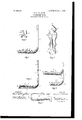
- the numeral 1 designates the upright or vertical member, which may be of any suitable shape and design and is preferably provided with two central openings 2, near its upper end, through which suitable fastenings, such as nails or screws, may be passed to secure the hook in place.
- the upright member 1 is curved outwardly at its lower end, as indicated at 3, from which curved portion extends the horizontal sup porting member 4, which is inclined upwardly and outwardly, so as to cause its upper surface to incline rearwardly.
- the supporting member 4 is formed with a convexed or rounded surface 5, as best shown in Figs. 2 and 6, which surface, as before described, inclines rearwardly, although it is slightly convex longitudinally of the supporting member 4, as indicated in the drawings. At its extreme outer end the rounded surface 5 of the supporting member 4 is merged intoa downturned and rounded end 6, thus forming a smooth and continuous rounded surface from the lower end of the downturned portion 6 to the rounded portion 3.
- the contour given the supporting member 4 by the surface 5, the downturned end 6, and the merging of the two together conforms to the natural hang of the garment and allows the same to rest easily on the said member4 and at the same time owing to the rearward inclination the tendency of the garment to ride off the supporting member when it is touched or moved is obviated.
- the hook may be made of any suitable material and in any suitable manner, such as by casting, stamping, drop-forging, and the various methods of producing metallic articles.
- the supporting member 4 is preferably cut away or formed on its under side with a concavity 7, which dies out toward the rear of the sup porting member and terminates in the rounded portion 3, as best shown in Fig. 3.
- a concavity 7 which dies out toward the rear of the sup porting member and terminates in the rounded portion 3, as best shown in Fig. 3.
- Fig. 4 I have illustrated a slightly-modified form which comprises in connection with the upright member 1 and the supportingmemher 4 a downwardly-extending vertical leg 8, worked from or connected to the rounded portion 3 and likewise provided at its lower end with a similar curved portion 3*, from which is projected an inclined supporting.
- member-4 shaped and constructed like the member 4, except as to its length, which is shorter than the length of the member 4, so
- a wardrobe-hook comprising a vertical member and a rounded and broadened garment-supporting member of approximately uniform width throughout its length and inclined rearwardly toward the vertical member and having its rounded and broadened surface gradually merged rearwardly into the vertical member,
- a wardrobe-hook comprising a vertical member and a rounded and broadened garment-supporting member of approximately uniform width throughout its length and inclined rearwardly toward the vertical member and having its rounded and broadened surface gradually merged rearwardly into the vertical member, the said garment-supporting member having its outer or forward end broadened and rounded and turned down.
Landscapes
- Holders For Apparel And Elements Relating To Apparel (AREA)
- Supports Or Holders For Household Use (AREA)
Description
No. 809,017. 7 PATENTBD JAN. 2, 1906. B. z. SCHRBYBR.
WARDROBE HOOK.
APPLICATION FILED FEB. 20. 1905.
INVENTUR B e y amfn Z. 56]! reg e I:
ATTORNEYS UNITED STATES PATENT OFFICE.
Specification of Letters Patent.
Patented Jan. 2, 1906.
Application filed February 20, 1905. Serial No. 246,365.
To all whomit may concern.
Be it known that I, BENJAMIN Z. SOHREYER, a citizen of the United States, residing at O- lumbus, in the county of Franklin and State of Ohio, have invented certain new and useful Improvements in Wardrobe-Hooks, of'which the following is a specification.
My invention relates to a new and useful improvement in wardrobe-hooks.
The object of the invention is to provide a hook for supporting garments formed and constructed to present a broad and rounded surface to the garment, so as to evenly and smoothly support the same and also to provide the hook with a rounded and downturned end over the surface of which the garment will easily hang without in any way being distorted or poked out of shape, as is common where garments, especially coats, are hung on hooks having upturned or sharp ends.
Finally, the object of the invention is to provide a device of the character described that will be strong, durable, efficient, and simple and inexpensive to construct.
WVith the above and other objects in view the invention consists of the novel details of construction and operation, a preferable embodiment of which is described in the specification and illustrated in the accompanying drawings, wherein F1gure1 is a side elevation of mylmproved hook. Fig. 2 is a front elevation. Fig. 3 is a vertical sectional view taken on the line a a: of Fig. 2. Fig. 4 is a side elevation of a modified form. Fig. 5 is a plan view, and Fig. 6 is a cross-sectional view, taken on the line 3 y of Fig. 1 and showing a portion of the upright member of the hook in elevation.
In the drawings, the numeral 1 designates the upright or vertical member, which may be of any suitable shape and design and is preferably provided with two central openings 2, near its upper end, through which suitable fastenings, such as nails or screws, may be passed to secure the hook in place. The upright member 1 is curved outwardly at its lower end, as indicated at 3, from which curved portion extends the horizontal sup porting member 4, which is inclined upwardly and outwardly, so as to cause its upper surface to incline rearwardly. The supporting member 4 is formed with a convexed or rounded surface 5, as best shown in Figs. 2 and 6, which surface, as before described, inclines rearwardly, although it is slightly convex longitudinally of the supporting member 4, as indicated in the drawings. At its extreme outer end the rounded surface 5 of the supporting member 4 is merged intoa downturned and rounded end 6, thus forming a smooth and continuous rounded surface from the lower end of the downturned portion 6 to the rounded portion 3.
By rounding the supporting member 4 and inclining its upper surface rearwardly, a garment such as a coat when hung upon the hook or the said supporting member will be prevented from riding off, and the surface 5 being proportionately broad and smooth will support the coat at the neck without tearing the collar or poking up the goods adjacent thereto or stretching and distorting the same, so as to injure the garment, as is. the case where hooks provided with upturned supporting members are employed. The contour given the supporting member 4 by the surface 5, the downturned end 6, and the merging of the two together conforms to the natural hang of the garment and allows the same to rest easily on the said member4 and at the same time owing to the rearward inclination the tendency of the garment to ride off the supporting member when it is touched or moved is obviated.
The hook may be made of any suitable material and in any suitable manner, such as by casting, stamping, drop-forging, and the various methods of producing metallic articles. For the purpose of lightening and facilitating the easy construction of the hook the supporting member 4 is preferably cut away or formed on its under side with a concavity 7, which dies out toward the rear of the sup porting member and terminates in the rounded portion 3, as best shown in Fig. 3. By so forming the member 4 it may be made throughout with comparatively the same thickness, which will greatly facilitate its production in case it should be desired to stamp the same, it being obvious that sheet metal might be successfully employed.
In Fig. 4 I have illustrated a slightly-modified form which comprises in connection with the upright member 1 and the supportingmemher 4 a downwardly-extending vertical leg 8, worked from or connected to the rounded portion 3 and likewise provided at its lower end with a similar curved portion 3*, from which is projected an inclined supporting.
member-4 shaped and constructed like the member 4, except as to its length, which is shorter than the length of the member 4, so
IIO
that garments may be hung thereon without interfering with the operation of the said upper member a.
Having now fully described my invention, what I claim, and desire to secure by Letters Patent, is
1. A wardrobe-hook comprising a vertical member and a rounded and broadened garment-supporting member of approximately uniform width throughout its length and inclined rearwardly toward the vertical member and having its rounded and broadened surface gradually merged rearwardly into the vertical member,
2. A wardrobe-hook comprising a vertical member and a rounded and broadened garment-supporting member of approximately uniform width throughout its length and inclined rearwardly toward the vertical member and having its rounded and broadened surface gradually merged rearwardly into the vertical member, the said garment-supporting member having its outer or forward end broadened and rounded and turned down.
In testimony whereof I affix my signature in presence of two witnesses.
BENJAMIN Z. SOHREYER. l/Vitnesses':
A. L. PHELPS, M. B. SOHLEYL
Priority Applications (1)
| Application Number | Priority Date | Filing Date | Title |
|---|---|---|---|
| US24636505A US809017A (en) | 1905-02-20 | 1905-02-20 | Wardrobe-hook. |
Applications Claiming Priority (1)
| Application Number | Priority Date | Filing Date | Title |
|---|---|---|---|
| US24636505A US809017A (en) | 1905-02-20 | 1905-02-20 | Wardrobe-hook. |
Publications (1)
| Publication Number | Publication Date |
|---|---|
| US809017A true US809017A (en) | 1906-01-02 |
Family
ID=2877498
Family Applications (1)
| Application Number | Title | Priority Date | Filing Date |
|---|---|---|---|
| US24636505A Expired - Lifetime US809017A (en) | 1905-02-20 | 1905-02-20 | Wardrobe-hook. |
Country Status (1)
| Country | Link |
|---|---|
| US (1) | US809017A (en) |
Cited By (1)
| Publication number | Priority date | Publication date | Assignee | Title |
|---|---|---|---|---|
| US20060024144A1 (en) * | 2003-10-10 | 2006-02-02 | Horvath John F | Three piece garage hook |
-
1905
- 1905-02-20 US US24636505A patent/US809017A/en not_active Expired - Lifetime
Cited By (5)
| Publication number | Priority date | Publication date | Assignee | Title |
|---|---|---|---|---|
| US20060024144A1 (en) * | 2003-10-10 | 2006-02-02 | Horvath John F | Three piece garage hook |
| US7661917B2 (en) * | 2003-10-10 | 2010-02-16 | Illinois Tool Works, Inc. | Three piece garage hook |
| US20100090074A1 (en) * | 2003-10-10 | 2010-04-15 | Illinois Tool Works Inc. | Three Piece Garage Hook |
| US7972100B2 (en) | 2003-10-10 | 2011-07-05 | Illinois Tool Works Inc. | Three piece garage hook |
| AU2006258139B2 (en) * | 2005-06-08 | 2010-06-17 | Illinois Tool Works Inc. | Holder assembly |
Similar Documents
| Publication | Publication Date | Title |
|---|---|---|
| US3348745A (en) | Garment hanger with end loading slot | |
| US809017A (en) | Wardrobe-hook. | |
| US505209A (en) | Albert white | |
| US791107A (en) | Garment and book support. | |
| US378201A (en) | Goat-hook | |
| US2006033A (en) | Hanger | |
| US451568A (en) | Hat hook or rest | |
| US2334036A (en) | Multiple garment hanger | |
| US1568538A (en) | Garment-hanger support | |
| US2643036A (en) | Garment hanger | |
| US399825A (en) | Hat and clothes rack | |
| US980907A (en) | Garment-hanger. | |
| US1205644A (en) | Garment-hanger. | |
| US766250A (en) | Dress-hanger. | |
| US2488621A (en) | Clothes hanger | |
| US707880A (en) | Clothes-hanger. | |
| US601354A (en) | The morris pcters co | |
| US857602A (en) | Clothes-hanger. | |
| US609743A (en) | Garment-hanger | |
| US1219476A (en) | Garment-hanger for auditorium-seats. | |
| USD15427S (en) | Design for a clothes-drier | |
| US1119135A (en) | Garment-hanger. | |
| US505336A (en) | Coat and hat hook | |
| US750325A (en) | Combination garment-suspender | |
| US175723A (en) | Improvement in card-suspending rings |