US8089004B2 - Semiconductor device including wiring excellent in impedance matching, and method for designing the same - Google Patents
Semiconductor device including wiring excellent in impedance matching, and method for designing the same Download PDFInfo
- Publication number
- US8089004B2 US8089004B2 US12/232,889 US23288908A US8089004B2 US 8089004 B2 US8089004 B2 US 8089004B2 US 23288908 A US23288908 A US 23288908A US 8089004 B2 US8089004 B2 US 8089004B2
- Authority
- US
- United States
- Prior art keywords
- wiring
- region
- semiconductor device
- interposer
- semiconductor chip
- Prior art date
- Legal status (The legal status is an assumption and is not a legal conclusion. Google has not performed a legal analysis and makes no representation as to the accuracy of the status listed.)
- Expired - Fee Related, expires
Links
Images


Classifications
-
- H—ELECTRICITY
- H05—ELECTRIC TECHNIQUES NOT OTHERWISE PROVIDED FOR
- H05K—PRINTED CIRCUITS; CASINGS OR CONSTRUCTIONAL DETAILS OF ELECTRIC APPARATUS; MANUFACTURE OF ASSEMBLAGES OF ELECTRICAL COMPONENTS
- H05K1/00—Printed circuits
- H05K1/02—Details
- H05K1/0213—Electrical arrangements not otherwise provided for
- H05K1/0216—Reduction of cross-talk, noise or electromagnetic interference
- H05K1/0228—Compensation of cross-talk by a mutually correlated lay-out of printed circuit traces, e.g. for compensation of cross-talk in mounted connectors
-
- G—PHYSICS
- G06—COMPUTING; CALCULATING OR COUNTING
- G06F—ELECTRIC DIGITAL DATA PROCESSING
- G06F30/00—Computer-aided design [CAD]
- G06F30/30—Circuit design
- G06F30/36—Circuit design at the analogue level
-
- H—ELECTRICITY
- H01—ELECTRIC ELEMENTS
- H01L—SEMICONDUCTOR DEVICES NOT COVERED BY CLASS H10
- H01L2224/00—Indexing scheme for arrangements for connecting or disconnecting semiconductor or solid-state bodies and methods related thereto as covered by H01L24/00
- H01L2224/01—Means for bonding being attached to, or being formed on, the surface to be connected, e.g. chip-to-package, die-attach, "first-level" interconnects; Manufacturing methods related thereto
- H01L2224/26—Layer connectors, e.g. plate connectors, solder or adhesive layers; Manufacturing methods related thereto
- H01L2224/31—Structure, shape, material or disposition of the layer connectors after the connecting process
- H01L2224/32—Structure, shape, material or disposition of the layer connectors after the connecting process of an individual layer connector
- H01L2224/321—Disposition
- H01L2224/32151—Disposition the layer connector connecting between a semiconductor or solid-state body and an item not being a semiconductor or solid-state body, e.g. chip-to-substrate, chip-to-passive
- H01L2224/32221—Disposition the layer connector connecting between a semiconductor or solid-state body and an item not being a semiconductor or solid-state body, e.g. chip-to-substrate, chip-to-passive the body and the item being stacked
- H01L2224/32225—Disposition the layer connector connecting between a semiconductor or solid-state body and an item not being a semiconductor or solid-state body, e.g. chip-to-substrate, chip-to-passive the body and the item being stacked the item being non-metallic, e.g. insulating substrate with or without metallisation
-
- H—ELECTRICITY
- H01—ELECTRIC ELEMENTS
- H01L—SEMICONDUCTOR DEVICES NOT COVERED BY CLASS H10
- H01L2224/00—Indexing scheme for arrangements for connecting or disconnecting semiconductor or solid-state bodies and methods related thereto as covered by H01L24/00
- H01L2224/01—Means for bonding being attached to, or being formed on, the surface to be connected, e.g. chip-to-package, die-attach, "first-level" interconnects; Manufacturing methods related thereto
- H01L2224/42—Wire connectors; Manufacturing methods related thereto
- H01L2224/47—Structure, shape, material or disposition of the wire connectors after the connecting process
- H01L2224/48—Structure, shape, material or disposition of the wire connectors after the connecting process of an individual wire connector
- H01L2224/4805—Shape
- H01L2224/4809—Loop shape
- H01L2224/48091—Arched
-
- H—ELECTRICITY
- H01—ELECTRIC ELEMENTS
- H01L—SEMICONDUCTOR DEVICES NOT COVERED BY CLASS H10
- H01L2224/00—Indexing scheme for arrangements for connecting or disconnecting semiconductor or solid-state bodies and methods related thereto as covered by H01L24/00
- H01L2224/01—Means for bonding being attached to, or being formed on, the surface to be connected, e.g. chip-to-package, die-attach, "first-level" interconnects; Manufacturing methods related thereto
- H01L2224/42—Wire connectors; Manufacturing methods related thereto
- H01L2224/47—Structure, shape, material or disposition of the wire connectors after the connecting process
- H01L2224/48—Structure, shape, material or disposition of the wire connectors after the connecting process of an individual wire connector
- H01L2224/481—Disposition
- H01L2224/48151—Connecting between a semiconductor or solid-state body and an item not being a semiconductor or solid-state body, e.g. chip-to-substrate, chip-to-passive
- H01L2224/48221—Connecting between a semiconductor or solid-state body and an item not being a semiconductor or solid-state body, e.g. chip-to-substrate, chip-to-passive the body and the item being stacked
- H01L2224/48225—Connecting between a semiconductor or solid-state body and an item not being a semiconductor or solid-state body, e.g. chip-to-substrate, chip-to-passive the body and the item being stacked the item being non-metallic, e.g. insulating substrate with or without metallisation
- H01L2224/48227—Connecting between a semiconductor or solid-state body and an item not being a semiconductor or solid-state body, e.g. chip-to-substrate, chip-to-passive the body and the item being stacked the item being non-metallic, e.g. insulating substrate with or without metallisation connecting the wire to a bond pad of the item
- H01L2224/48228—Connecting between a semiconductor or solid-state body and an item not being a semiconductor or solid-state body, e.g. chip-to-substrate, chip-to-passive the body and the item being stacked the item being non-metallic, e.g. insulating substrate with or without metallisation connecting the wire to a bond pad of the item the bond pad being disposed in a recess of the surface of the item
-
- H—ELECTRICITY
- H01—ELECTRIC ELEMENTS
- H01L—SEMICONDUCTOR DEVICES NOT COVERED BY CLASS H10
- H01L2224/00—Indexing scheme for arrangements for connecting or disconnecting semiconductor or solid-state bodies and methods related thereto as covered by H01L24/00
- H01L2224/73—Means for bonding being of different types provided for in two or more of groups H01L2224/10, H01L2224/18, H01L2224/26, H01L2224/34, H01L2224/42, H01L2224/50, H01L2224/63, H01L2224/71
- H01L2224/732—Location after the connecting process
- H01L2224/73251—Location after the connecting process on different surfaces
- H01L2224/73265—Layer and wire connectors
-
- H—ELECTRICITY
- H01—ELECTRIC ELEMENTS
- H01L—SEMICONDUCTOR DEVICES NOT COVERED BY CLASS H10
- H01L24/00—Arrangements for connecting or disconnecting semiconductor or solid-state bodies; Methods or apparatus related thereto
- H01L24/73—Means for bonding being of different types provided for in two or more of groups H01L24/10, H01L24/18, H01L24/26, H01L24/34, H01L24/42, H01L24/50, H01L24/63, H01L24/71
-
- H—ELECTRICITY
- H01—ELECTRIC ELEMENTS
- H01L—SEMICONDUCTOR DEVICES NOT COVERED BY CLASS H10
- H01L2924/00—Indexing scheme for arrangements or methods for connecting or disconnecting semiconductor or solid-state bodies as covered by H01L24/00
- H01L2924/15—Details of package parts other than the semiconductor or other solid state devices to be connected
- H01L2924/151—Die mounting substrate
- H01L2924/1517—Multilayer substrate
- H01L2924/15182—Fan-in arrangement of the internal vias
-
- H—ELECTRICITY
- H01—ELECTRIC ELEMENTS
- H01L—SEMICONDUCTOR DEVICES NOT COVERED BY CLASS H10
- H01L2924/00—Indexing scheme for arrangements or methods for connecting or disconnecting semiconductor or solid-state bodies as covered by H01L24/00
- H01L2924/15—Details of package parts other than the semiconductor or other solid state devices to be connected
- H01L2924/151—Die mounting substrate
- H01L2924/1517—Multilayer substrate
- H01L2924/15192—Resurf arrangement of the internal vias
-
- H—ELECTRICITY
- H01—ELECTRIC ELEMENTS
- H01L—SEMICONDUCTOR DEVICES NOT COVERED BY CLASS H10
- H01L2924/00—Indexing scheme for arrangements or methods for connecting or disconnecting semiconductor or solid-state bodies as covered by H01L24/00
- H01L2924/15—Details of package parts other than the semiconductor or other solid state devices to be connected
- H01L2924/151—Die mounting substrate
- H01L2924/153—Connection portion
- H01L2924/1531—Connection portion the connection portion being formed only on the surface of the substrate opposite to the die mounting surface
- H01L2924/15311—Connection portion the connection portion being formed only on the surface of the substrate opposite to the die mounting surface being a ball array, e.g. BGA
-
- H—ELECTRICITY
- H01—ELECTRIC ELEMENTS
- H01L—SEMICONDUCTOR DEVICES NOT COVERED BY CLASS H10
- H01L2924/00—Indexing scheme for arrangements or methods for connecting or disconnecting semiconductor or solid-state bodies as covered by H01L24/00
- H01L2924/30—Technical effects
- H01L2924/301—Electrical effects
- H01L2924/30107—Inductance
-
- H—ELECTRICITY
- H01—ELECTRIC ELEMENTS
- H01L—SEMICONDUCTOR DEVICES NOT COVERED BY CLASS H10
- H01L2924/00—Indexing scheme for arrangements or methods for connecting or disconnecting semiconductor or solid-state bodies as covered by H01L24/00
- H01L2924/30—Technical effects
- H01L2924/301—Electrical effects
- H01L2924/3011—Impedance
-
- H—ELECTRICITY
- H05—ELECTRIC TECHNIQUES NOT OTHERWISE PROVIDED FOR
- H05K—PRINTED CIRCUITS; CASINGS OR CONSTRUCTIONAL DETAILS OF ELECTRIC APPARATUS; MANUFACTURE OF ASSEMBLAGES OF ELECTRICAL COMPONENTS
- H05K1/00—Printed circuits
- H05K1/02—Details
- H05K1/14—Structural association of two or more printed circuits
- H05K1/141—One or more single auxiliary printed circuits mounted on a main printed circuit, e.g. modules, adapters
-
- H—ELECTRICITY
- H05—ELECTRIC TECHNIQUES NOT OTHERWISE PROVIDED FOR
- H05K—PRINTED CIRCUITS; CASINGS OR CONSTRUCTIONAL DETAILS OF ELECTRIC APPARATUS; MANUFACTURE OF ASSEMBLAGES OF ELECTRICAL COMPONENTS
- H05K2201/00—Indexing scheme relating to printed circuits covered by H05K1/00
- H05K2201/10—Details of components or other objects attached to or integrated in a printed circuit board
- H05K2201/10227—Other objects, e.g. metallic pieces
- H05K2201/10378—Interposers
Definitions
- the present invention relates to a semiconductor device and a method for designing the same.
- FIG. 17 is a plan view of the conventional semiconductor device
- FIG. 18 is a cross-sectional view thereof.
- a semiconductor device 800 includes an interposer 802 and a semiconductor chip 808 .
- the semiconductor chip 808 is mounted via a mounting material 812 , with its circuit-formed surface upside.
- the semiconductor chip 808 is sealed with a molding resin 820 .
- the interposer 802 includes an insulating layer 804 including a wiring 810 , and solder resists 806 covering surfaces of the insulating layer 804 .
- the wiring 810 is exposed at the bottom of an opening 812 provided in one of the solder resists 806 , and the exposed portion of the wiring 810 and the circuit (not shown) on the semiconductor chip 808 are electrically connected via a wire 814 .
- the width and thickness of the wiring 810 is uniform in the interposer 802 .
- FIG. 17 shows only one wiring 810 , but an actual semiconductor device normally includes a plurality of wirings.
- solder ball 818 is provided as an external connection terminal.
- the solder ball 818 and the wiring 810 are electrically connected via a through electrode 816 .
- Japanese Patent Laid-Open No. 7-106759 discloses a thin-film multilayer substrate having a stripline structure or a microstripline structure, wherein the impedances of a signal line and a device are matched by changing the width, thickness and/or material of the signal line.
- the semiconductor device 800 has a problem in that when a high-speed signal is transmitted through the wiring 810 , reflection and/or waveform distortion of the signal may occur, deteriorating the transmission characteristics.
- the wiring 810 has a capacitance between it and a conductor having a fixed potential. Furthermore, the inductance value of the wiring 810 varies as a result of interaction between it and the conductor having a fixed potential. Thus, conventionally, the characteristic impedance of the wiring 810 is estimated by calculating capacitance and inductance values for the entire wiring 810 with a power supply layer or a ground layer in a printed wiring board (not shown), on which the semiconductor device 800 is mounted, as a reference conductor plane.
- the semiconductor chip 808 acts as a reference conductor plane for the wiring 810 and changes the capacitance and/or inductance of the region of the wiring 810 below the semiconductor chip 808 , and as a result, the characteristic impedance of the region of the wiring will change. Consequently, a characteristic impedance mismatch occurs in the middle of the wiring 810 , which causes reflection and/or waveform distortion of a signal, deteriorating the transmission characteristics.
- the aforementioned problem is especially significant for a high-speed digital signal, etc., which has sharply falling and rising waves. Accordingly, with the recent increase in speed of semiconductor devices, the problem has become increasingly serious.
- a chip capacitor and/or a chip resistor is added in the interposer to match the characteristic impedances. This requires addition of members and an increase in manufacturing steps, causing a rise in manufacturing costs.
- a semiconductor device provides a semiconductor device comprising an interposer, and a semiconductor chip mounted on the interposer, wherein: in a plan view, the interposer includes a first region overlapping the semiconductor chip, and a second region excluding the first region, and the interposer includes at least one wiring therein, the wiring being formed astride the first region and the second region; and a cross-sectional area of the wiring in the first region of the interposer and a cross-sectional area of the wiring in the second region of the interposer are different from each other.
- a characteristic impedance of the wiring in the first region may be substantially equal to a characteristic impedance of the wiring in the second region.
- a width of the wiring in the first region may be narrower than a width of the wiring in the second region.
- a thickness of the wiring in the first region may be thinner than a thickness of the wiring in the second region. Also, a lower surface of the wiring in the first region and a lower surface of the wiring in the second region may be on a same plane.
- the interposer may include a plurality of wiring layers, and the wiring in the first region and the wiring in the second region may be provided in different wiring layers.
- a method for designing a semiconductor device provides a method for designing a semiconductor device including an interposer with a semiconductor chip mounted thereon and a printed wiring board with the interposer mounted thereon, in a plan view, the interposer including a first region overlapping the semiconductor chip, and a second region excluding the first region, and the interposer including at least one wiring therein, the wiring being formed astride the first region and the second region, the method comprising: calculating a capacitance and an inductance of the wiring in the second region with a wiring layer in the printed wiring board or the interposer as a reference conductor plane to calculate a characteristic impedance of the wiring in the second region; calculating a capacitance and an inductance of the wiring in the first region with the wiring layer in the printed wiring board or the interposer as a reference conductor plane, and a capacitance and an inductance of the wiring in the first region with a surface of the semiconductor chip facing the interposer as a reference conductor plane
- the “reference conductor plane” refers to a conductor having a fixed potential, and may be, e.g., a power supply layer or a ground layer in the printed wiring board.
- the semiconductor chip is also taken into consideration as a reference conductor plane.
- the present invention enables the provision of a semiconductor device having favorable transmission characteristics that provide an impedance match over the entire wiring in the interposer without addition of passive components such as a chip capacitor and/or a chip resistor, etc., and a method for designing the device.
- FIG. 1 is a plan view of a first embodiment of a semiconductor device according to the present invention.
- FIGS. 2A to 2C are cross-sectional views of a first embodiment of a semiconductor device according to the present invention.
- FIG. 3 is a diagram for describing a method for designing a first embodiment of a semiconductor device according to the present invention
- FIG. 4 is a diagram for describing a method for designing a first embodiment of a semiconductor device according to the present invention
- FIG. 5 is a flowchart illustrating a method for designing a first embodiment of a semiconductor device according to the present invention
- FIG. 6 is a plan view of a second embodiment of a semiconductor device according to the present invention.
- FIGS. 7A to 7C are cross-sectional views of a second embodiment of a semiconductor device according to the present invention.
- FIG. 8A to 8C are cross-sectional views of a third embodiment of a semiconductor device according to the present invention.
- FIG. 9 is a plan view of a fourth embodiment of a semiconductor device according to the present invention.
- FIGS. 10A to 10C are cross-sectional views of a fourth embodiment of a semiconductor device according to the present invention.
- FIG. 11 is a plan view of a modification of an embodiment
- FIG. 12 is a cross-sectional view of a modification of an embodiment
- FIG. 13 is a plan view of a modification of an embodiment
- FIGS. 14A to 14C are cross-sectional views of a modification of an embodiment
- FIG. 15 is a plan view of a modification of an embodiment
- FIG. 16 is a cross-sectional view of a modification of an embodiment
- FIG. 17 is a plan view of a conventional semiconductor device.
- FIG. 18A to 18C are cross-sectional views of a conventional semiconductor device.
- FIG. 1 is a plan view of the configuration of a semiconductor device 100 according to the present embodiment.
- FIG. 2A is a cross-sectional view of the semiconductor device 100 taken along A 1 -A 1 ′ of FIG. 1 .
- FIG. 2 B is an enlarged view of a portion of the semiconductor device 100 around a wiring in cross section taken along A 2 -A 2 ′ of FIG. 1 .
- FIG. 2C is an enlarged view of a portion of the semiconductor device 100 around a wiring in cross section taken along A 3 -A 3 ′ of FIG. 1 .
- a molding resin 120 is not shown.
- the semiconductor device 100 includes an interposer 102 and a semiconductor chip 108 .
- the semiconductor chip 108 is mounted via a mounting material 112 , with its circuit-formed surface upside.
- the semiconductor chip 108 may be, e.g., an LSI having a logic circuit function, an LSI having a general-purpose memory circuit function, or an LSI having an embedded DRAM circuit function.
- the semiconductor chip 108 is an LSI having a logic circuit function.
- the interposer 102 includes an insulating layer 104 including multilayer wirings, and solder resists 106 covering surfaces thereof. In FIG. 2 , only one wiring layer in the interposer 102 is shown. In one of the solder resists 106 , an opening 122 is provided, and at the bottom of the opening, a wiring 110 is exposed, the exposed portion of the wiring 110 and a pad (not shown) on the semiconductor chip 108 are electrically connected via a wire 114 .
- the interposer 102 includes at least one wiring 110 therein.
- the wiring 110 is a signal line.
- the interposer 102 includes a first region 150 overlapping the semiconductor chip 108 in a plan view, and a second region 160 excluding the first region 150 .
- FIG. 1 shows only one wiring 110 , but an actual semiconductor device includes a plurality of wirings.
- the wiring 110 is formed astride the first region 150 and the second region 160 in a plan view. Also, as shown in FIGS. 2B and 2C , the cross-sectional area of the wiring 110 in the interposer 102 is different between the first region 150 and the second region 160 . More specifically, in the present embodiment, the width of the wiring in the first region 150 is narrower than the width of the wiring in the second region 160 .
- a through electrode 116 provided in the interposer 102 electrically connects the wiring 110 and a solder ball provided on the back-surface of the interposer.
- the “reference conductor plane” means a conductor having a fixed potential.
- Characteristic impedance calculation requires a capacitance per unit length.
- w is the width of the wiring [mm]
- h is the distance between the wiring and the reference conductor plane [mm]
- the inductance per centimeter of the length of the wiring can be calculated by the following formula.
- L 0 1.97 ⁇ 10 ⁇ 9 ⁇ ln(2 ⁇ h/w )[ H] [Formula 4]
- the characteristic impedance Z 0 of the wiring can be calculated by assigning the results of calculations according to formulae 2 and 3 to formula 4.
- a characteristic impedance is calculated with a power supply layer or a ground layer provided in a printed wiring board or an interposer as a reference conductor plane.
- the cross-sectional area, such as the width and thickness, of the wiring in the interposer is designed to be uniform.
- the semiconductor chip is mounted on an interposer, and in addition, the semiconductor chip is closer to the wiring than the power supply layer or the ground layer in the printed wiring board.
- the semiconductor chip also acts as a reference conductor plane for the wiring, which affects the capacitance and inductance of the wiring.
- the semiconductor device is designed taking the semiconductor chip into account as a reference conductor plane for the wiring as well for the region where the interposer and the semiconductor chip overlap in a plan view (the first region).
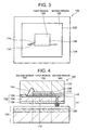
- FIGS. 3 and 4 are diagrams illustrating a method for designing the semiconductor device 100 according to the present invention.
- the semiconductor device 100 is mounted on a printed wiring board 124 .
- the interposer 102 includes the first region 150 overlapping the semiconductor chip 108 , and the second region 160 excluding the first region 150 .
- the interposer 102 includes at least one wiring 110 formed astride the first region 150 and the second region 160 .
- the capacitance and the inductance of the wiring is calculated with a wiring layer 126 in the printed wiring board 124 as a reference conductor plane, and the characteristic impedance of the wiring in the second region 160 is calculated based on the calculation result.
- the capacitance and inductance of the wiring with the wiring layer 126 in the printed wiring board 124 as a reference conductor plane, and the capacitance and inductance of the wiring with the semiconductor chip 108 as a reference conductor plane are both calculated, and the characteristic impedance of the wiring in the first region 150 is calculated based on the calculation results.
- the characteristic impedance in the first region 150 and the characteristic impedance in the second region 160 are made to be substantially the same based on the above-described characteristic impedance calculations by making the cross-sectional area of the wiring 110 in the interposer 102 in the second region 160 and the cross-sectional area of the wiring 110 in the interposer 102 in the first region 150 to be different from each other.
- FIG. 5 is a flowchart illustrating a method for designing the semiconductor device 100 .
- the semiconductor device structure information may include, e.g., the thickness of each layer, the thickness of a mounting material, the height of solder balls, the positions of the power supply/ground layers in the printed wiring board.
- the property values of the materials included in the semiconductor device may include the values of the relative permittivities of the respective materials.
- the capacitance and inductance of the wiring in the second region 160 is calculated with the cross-sectional area, such as the width and/or thickness, of the wiring changed and with a wiring layer in the printed wiring board as a reference conductor plane.
- the capacitance and inductance formulae 2 and 3 are used.
- several different characteristic impedances in the second region are calculated for the respective cross-sectional areas using formula 4 (S 102 ).
- a cross-sectional area for the wiring in the second region 160 is selected based on the calculation results at step S 102 so that the characteristic impedance in the second region 160 has a desired value (S 103 ).
- the desired value may be, e.g., a value substantially equal to the input/output impedance of the semiconductor chip 108 .
- the capacitance and inductance of the wiring in the first region 150 is calculated with the cross-sectional area, such as the width and/or thickness, of the wiring changed and with the wiring layer in the printed wiring board as a reference conductor plane.
- the capacitance and inductance formulae 2 and 3 are used.
- several different characteristic impedances in the first region are calculated for the respective cross-sectional areas using formula 4 (S 104 ).
- a cross-sectional area for the wiring in the first region 150 is selected based on the calculation results at step S 104 so that the characteristic impedance in the first region 150 has a desired value (S 105 ).
- the desired value may be, e.g., a value substantially equal to the value selected at step S 103 .
- the characteristic impedance of the wiring in the first region and the characteristic impedance of the wiring in the second region can be made to be substantially equal to each other.
- both the width and thickness of the wiring are equal between the first region and the second region.
- the characteristic impedance in the second region having no semiconductor chip above the wiring was 56 ⁇
- that in the first region having a semiconductor chip above the wiring was 35 ⁇ , which is lower than that in the second region by nearly 40%.
- Comparative example 2 as in comparative example 1, is constructed so that both the width and thickness of the wiring is equal between the first region and the second region, but the width of the wiring is narrowed to 40 ⁇ m in both the first region and the second region.
- the cross-sectional area of the wiring 110 in the interposer 102 is different between the first region 150 and the second region 160 . More specifically, the width of the wiring 110 in the first region is narrower than the width of the wiring 110 in the second region. Consequently, the characteristic impedance in the first region and the characteristic impedance in the second region become substantially equal to each other. Accordingly, it is possible to reduce waveform distortion and/or reflection of a signal travelling in the wiring 110 . Furthermore, as a result of reduction of reflection and noise of a signal, a desired stable signal can be input to the semiconductor chip 108 .
- the semiconductor chip 108 is an LSI having a logic circuit function. Since an LSI having a logic circuit function is required to operate at high speed, it is particularly largely affected by the effect of reflection of a signal caused by a difference in characteristic impedance. Accordingly, the semiconductor device according to the present invention that can provide a characteristic impedance match over the entire wiring is particularly effective where it incorporates an LSI having a logic circuit function therein.
- the present embodiment can provide an impedance match over the entire wiring in the interposer without addition of passive components such as a chip capacitor and/or a chip resistor. Accordingly, the structure of the interposer 102 can be simplified compared to conventional ones, suppressing an increase in size and complexity of the interposer 102 . Furthermore, the need for a new equipment investment for incorporating such passive components can be eliminated, and the device can be manufactured with the existing equipment, enabling reduction of the manufacturing costs.
- the capacity of the center part of the surface of the interposer 102 , on which the semiconductor chip is mounted, to have wirings thereon is enhanced.
- the wiring which has conventionally been arranged in an inner portion of the interposer, can be arranged in the outermost surface layer of the interposer 102 .
- the power supply layer or the ground layer in the interposer can be formed on the entire wiring layer, enabling the semiconductor device 100 to operate stably.
- the capacity of the center part of the surface of the interposer 102 , on which the semiconductor chip is mounted, to have wirings thereon is enhanced, and the wiring, which has been arranged in an inner portion of the interposer, can be arranged in the outermost surface layer of the interposer 102 .
- variation in the density of the wirings in the outermost surface layer of the interposer 102 can be prevented, providing a uniform density.
- irregularities of the surface caused due to erosion or dishing, etc. can be suppressed in a planarization process during manufacturing of an interposer.
- FIG. 6 is a plan view of the configuration of a semiconductor device 200 according to a second embodiment.
- FIG. 7A is a cross-sectional view of the semiconductor device 200 taken along B 1 -B 1 ′ of FIG. 6 .
- FIG. 7B is an enlarged view of a portion of the semiconductor device 200 around a wiring in cross section taken along B 2 -B 2 ′ of FIG. 6 .
- FIG. 7C is an enlarged view of a portion of the semiconductor device 200 around a wiring in cross section taken along B 3 -B 3 ′ of FIG. 6 .
- a molding resin 120 is not shown.
- the semiconductor device 200 is different from the semiconductor device 100 in that a wiring 210 adjacent to a wiring 110 is arranged to transmit a differential signal.
- Example designs of the semiconductor device 200 using a differential signal are shown in Table 2.
- both the width and thickness of the wiring are equal between the first region and the second region.
- the characteristic impedance in the second region was 107 ⁇
- that in the first region was 94 ⁇ , which is lower than that in the second region by no less than 10%.
- the width of the wiring in the first region was narrowed from 80 ⁇ m to 50 ⁇ m.
- the semiconductor device and designing method according to the present invention are also effective for a wiring that handles a differential signal.
- FIGS. 8A , 8 B and 8 C are cross-sectional views of a third embodiment of a semiconductor device 300 according to the present invention. Since the plan view in the present embodiment is similar to that in the first embodiment, FIG. 1 is applied.
- FIG. 8A is a cross-sectional view taken along A 1 -A 1 ′ of FIG. 1 .
- FIG. 8B is an enlarged view of a portion around a wiring in cross section taken along A 2 -A 2 ′ of FIG. 1 .
- FIG. 8C is an enlarged view of a portion around a wiring in cross section taken along A 3 -A 3 ′ of FIG. 1 .
- an interposer 102 includes four wiring layers, which are wiring layers L 1 , L 2 , L 3 and L 4 from the side of the interposer 102 where the semiconductor chip 108 is mounted.
- a wiring 110 is provided in the wiring layer L 1 .
- the wiring 110 is provided in the wiring layer L 2 .
- the distance between the semiconductor chip 108 and the wiring 110 in the first region 150 is larger than that of the first embodiment.
- the width of the wiring 110 in the first region 150 is narrowed.
- the effect of the semiconductor chip 108 on the wiring in the first region 150 is reduced, enabling the width of the wiring 110 to be wider than that of the semiconductor device according to the first embodiment. Consequently, the characteristic impedances of the first region and the second region can be matched while suppressing an increase in electric resistance of the wiring caused as a result of the wiring being narrowed.
- Table 3 indicates examples of the results of designing the semiconductor device 300 according to the present embodiment.
- the rest of the values were the same in the first embodiment.
- FIG. 9 is a plan view of the configuration of a semiconductor device according to a fourth embodiment.
- FIG. 10A is a cross-sectional view of the semiconductor device taken along C 1 -C 1 ′ of FIG. 9 .
- FIG. 10B is an enlarged view of a portion around a wiring of the semiconductor device in cross section taken along C 2 -C 2 ′ of FIG. 9 .
- FIG. 10C is an enlarged view of a portion around a wiring of the semiconductor device in cross section taken along C 3 -C 3 ′ of FIG. 9 .
- a molding resin 120 is not shown.
- the width of the wiring are the same between the first region and the second region, and the cross-sectional area of the wiring is changed by reducing the thickness of the wiring in the first region. Furthermore, the lower surface of the wiring in the first region and that in the second region are on the same plane. As a result, the distance between the semiconductor chip 108 and the wiring 110 in the first region becomes large, enabling reduction of the effect of the semiconductor chip 108 on the wiring 110 . Accordingly, the characteristic impedance of the wiring in the first region and that in the second region can be made to be substantially equal to each other.
- the semiconductor device according to the present invention is not limited to the above-described embodiments, various modifications are possible.
- the above embodiments have been described in terms of the case where one semiconductor chip is mounted on the interposer 102 , a plurality of semiconductor chips may be mounted.
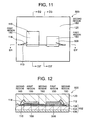
- FIG. 11 is a plan view of the configuration of a semiconductor device where a plurality of semiconductor chips are mounted.
- FIG. 12 is a cross-sectional view of the semiconductor device taken along D 1 -D 1 ′ of FIG. 12 . The cross-sectional view in the direction perpendicular to the direction in which the wiring extends is omitted because it is similar to that of embodiment 1.
- a semiconductor device 500 includes an interposer 102 with a semiconductor chip 108 and a semiconductor chip 508 mounted thereon.
- the semiconductor chip 108 is an LSI having a logic circuit function
- the semiconductor chip 508 is a LSI having a general-purpose memory circuit function.
- the regions where the semiconductor chip 108 and the semiconductor chip 508 overlap in a plan view are first regions 150 , and the region excluding the first regions 150 is a second region 160 .
- the cross-sectional area of a wiring 110 in each of the first regions 150 is different from that in the second region 160 . More specifically, the wiring width in each of the first regions 150 is narrower than the wiring width in the second region 160 .
- the semiconductor device 500 in FIGS. 11 and 12 has a SiP (System in Package) structure.
- SiP System in Package
- the portions below the semiconductor chips are often used for wiring regions, and accordingly, the semiconductor device and designing method according to the present invention are effective means.
- EMC Electro-Magnetic Compatibility
- FIG. 13 shows an example of a semiconductor device 600 in which a wiring 110 extends only up to the middle of a semiconductor chip 108 in a plan view.
- FIG. 14A is a cross-sectional view of the semiconductor device 600 taken along E 1 -E 1 ′ of FIG. 13 .
- FIG. 14B is an enlarged view of a portion around the wiring of the semiconductor device 600 in cross section taken along E 2 -E 2 ′ of FIG. 13 .
- FIG. 14C is an enlarged view of a portion around the wiring of the semiconductor device 600 in cross section taken along E 3 -E 3 ′ of FIG. 13 .
- a molding resin 120 is not shown.
- the wiring 110 extends up to the middle of a first region 150 , and is connected to a wiring 610 in a lower layer via a through electrode 616 .
- the wiring 610 is arranged just below the wiring 110 , and extends up to a second region 160 and is connected to a solder ball. Even in such wiring layout, a characteristic impedance match over the entire wiring can be provided by narrowing the widths of the wiring 110 and the wiring 610 in the first region 150 .
- the characteristic impedances may be matched by changing the thickness of the mounting material 112 used to mount the semiconductor chip 108 on the interposer to change the distance between the semiconductor chip 108 and the wiring 110 .
- This configuration is effective for the case where a significant increase in electric resistance of the wiring 110 in the first region occurs if the width of the wiring is overly narrowed.
- the thickness of the mounting material 112 is increased to increase the distance between the semiconductor chip 108 and the wiring 110 , enabling the provision of a characteristic impedance match over the entire wiring 110 .
- the mounting material 112 is of an insulating material, a conductive material, such as Ag paste, may be used. In this case, the mounting material acts as a reference conductor plane.
- FIG. 15 is a plan view of the configuration of a semiconductor device 700 in which a semiconductor chip is mounted by means of flip-chip bonding.
- FIG. 16 is a cross-sectional view of the semiconductor device taken along F 1 -F 1 ′ of FIG. 16 . The cross-sectional view in the direction perpendicular to the direction in which the wiring extends is omitted because it is similar to that of embodiment 3.
- a semiconductor chip 108 is mounted by means of flip-chip bonding via solder bumps 710 .
- a characteristic impedance match can be provided over the entire wiring 110 by reducing the width of the wiring 110 in a first region 150 .
- the semiconductor chip 108 may be embedded in the interposer 102 .
- the semiconductor device and designing method according to the present invention are highly effective.
- a power supply layer in the printed wiring board may be a reference conductor plane since the reference conductor plane may be any conductor having a fixed potential.
- a wiring layer having a fixed potential that is, a ground layer or a power supply layer
- the wiring layer in the interposer 102 may used as a reference conductor plane.
Abstract
Description
Z0=√(L0/C0)[Ω] [Formula 1]
Here, the “reference conductor plane” means a conductor having a fixed potential.
C=ε0εrS/d[F] [Formula 2]
C0=10−2×ε0εrw/h[F]. [Formula 3]
L0=1.97×10⁻⁹×ln(2πh/w)[H] [Formula 4]
| TABLE 1 | |||
| Characteristic | |||
| Wiring Width | Impedance | ||
| Comparative | Wiring | Second | Second | |||
| Example | Thickness | First Region | Region | | Region | |
| 1 | 15 μm | 270 μm | 270 μm | 35 Ω | 56 |
|
| 2 | 15 μm | 40 μm | 40 μm | 84 Ω | 98 |
|
| 3 | 15 μm | 80 μm | 270 μm | 62 Ω | 56 Ω | |
| TABLE 2 | |||
| Characteristic | |||
| Wiring Width | Impedance | ||
| Comparative | Wiring | Second | Second | |||
| Example | Thickness | First Region | Region | | Region | |
| 4 | 15 μm | 80 μm | 80 μm | 94 Ω | 107 Ω | |
| 5 | 15 μm | 50 μm | 80 μm | 113 Ω | 107 Ω | |
| TABLE 3 | |||
| Characteristic | |||
| Wiring Width | Impedance | ||
| Comparative | Wiring | Second | Second | ||
| Example | Thickness | First Region | Region | First Region | Region |
| 6 | 15 |
150 μm | 270 μm | 49 Ω | 56 Ω |
| 7 | 15 μm | 40 μm | 40 μm | 79 Ω | 97 Ω |
| 8 | 15 μm | 85 μm | 270 μm | 60 Ω | 56 Ω |
Claims (12)
Applications Claiming Priority (3)
| Application Number | Priority Date | Filing Date | Title |
|---|---|---|---|
| JP253155/2007 | 2007-09-28 | ||
| JP2007-253155 | 2007-09-28 | ||
| JP2007253155A JP5051836B2 (en) | 2007-09-28 | 2007-09-28 | Semiconductor device and design method thereof |
Publications (2)
| Publication Number | Publication Date |
|---|---|
| US20090084592A1 US20090084592A1 (en) | 2009-04-02 |
| US8089004B2 true US8089004B2 (en) | 2012-01-03 |
Family
ID=40506901
Family Applications (1)
| Application Number | Title | Priority Date | Filing Date |
|---|---|---|---|
| US12/232,889 Expired - Fee Related US8089004B2 (en) | 2007-09-28 | 2008-09-25 | Semiconductor device including wiring excellent in impedance matching, and method for designing the same |
Country Status (2)
| Country | Link |
|---|---|
| US (1) | US8089004B2 (en) |
| JP (1) | JP5051836B2 (en) |
Cited By (1)
| Publication number | Priority date | Publication date | Assignee | Title |
|---|---|---|---|---|
| US20210265269A1 (en) * | 2018-08-09 | 2021-08-26 | Sony Semiconductor Solutions Corporation | Semiconductor integrated circuit and electronic apparatus |
Families Citing this family (4)
| Publication number | Priority date | Publication date | Assignee | Title |
|---|---|---|---|---|
| JP2009246317A (en) * | 2008-04-01 | 2009-10-22 | Nec Electronics Corp | Semiconductor device and wiring substrate |
| US8745559B2 (en) | 2011-07-06 | 2014-06-03 | Taiwan Semiconductor Manufacturing Co., Ltd. | Systems and methods for creating frequency-dependent netlist |
| US8453095B2 (en) * | 2011-07-06 | 2013-05-28 | Taiwan Semiconductor Manufacturing Co., Ltd. | Systems and methods for creating frequency-dependent netlist |
| KR20130064477A (en) * | 2011-12-08 | 2013-06-18 | 삼성전자주식회사 | Printed circuit board(pcb) comprising one-layer wire pattern |
Citations (6)
| Publication number | Priority date | Publication date | Assignee | Title |
|---|---|---|---|---|
| JPH07106759A (en) | 1993-09-30 | 1995-04-21 | Sony Corp | Thin-film multilayered substrate |
| JP2000174168A (en) | 1998-12-03 | 2000-06-23 | Sanyo Electric Co Ltd | Semiconductor device |
| US6469908B2 (en) * | 2000-03-31 | 2002-10-22 | Intel Corporation | Dual-socket interposer and method of fabrication therefor |
| US7110263B2 (en) * | 2004-03-09 | 2006-09-19 | Intel Corporation | Reference slots for signal traces |
| US20070290302A1 (en) * | 2006-06-14 | 2007-12-20 | Sharp Kabushiki Kaisha | IC chip package, and image display apparatus using same |
| US20100315790A1 (en) * | 2005-01-31 | 2010-12-16 | Sanyo Electric Co., Ltd. | Circuit Substrate Structure And Circuit Apparatus |
Family Cites Families (3)
| Publication number | Priority date | Publication date | Assignee | Title |
|---|---|---|---|---|
| JP3500268B2 (en) * | 1997-02-27 | 2004-02-23 | 京セラ株式会社 | High frequency input / output terminal and high frequency semiconductor element storage package using the same |
| JP2001127192A (en) * | 1999-10-27 | 2001-05-11 | Kyocera Corp | Semiconductor element mounting board |
| JP2001203300A (en) * | 2000-01-18 | 2001-07-27 | Matsushita Electric Ind Co Ltd | Board for wiring, semiconductor device and producing method for board for wiring |
-
2007
- 2007-09-28 JP JP2007253155A patent/JP5051836B2/en not_active Expired - Fee Related
-
2008
- 2008-09-25 US US12/232,889 patent/US8089004B2/en not_active Expired - Fee Related
Patent Citations (6)
| Publication number | Priority date | Publication date | Assignee | Title |
|---|---|---|---|---|
| JPH07106759A (en) | 1993-09-30 | 1995-04-21 | Sony Corp | Thin-film multilayered substrate |
| JP2000174168A (en) | 1998-12-03 | 2000-06-23 | Sanyo Electric Co Ltd | Semiconductor device |
| US6469908B2 (en) * | 2000-03-31 | 2002-10-22 | Intel Corporation | Dual-socket interposer and method of fabrication therefor |
| US7110263B2 (en) * | 2004-03-09 | 2006-09-19 | Intel Corporation | Reference slots for signal traces |
| US20100315790A1 (en) * | 2005-01-31 | 2010-12-16 | Sanyo Electric Co., Ltd. | Circuit Substrate Structure And Circuit Apparatus |
| US20070290302A1 (en) * | 2006-06-14 | 2007-12-20 | Sharp Kabushiki Kaisha | IC chip package, and image display apparatus using same |
Cited By (1)
| Publication number | Priority date | Publication date | Assignee | Title |
|---|---|---|---|---|
| US20210265269A1 (en) * | 2018-08-09 | 2021-08-26 | Sony Semiconductor Solutions Corporation | Semiconductor integrated circuit and electronic apparatus |
Also Published As
| Publication number | Publication date |
|---|---|
| US20090084592A1 (en) | 2009-04-02 |
| JP5051836B2 (en) | 2012-10-17 |
| JP2009088063A (en) | 2009-04-23 |
Similar Documents
| Publication | Publication Date | Title |
|---|---|---|
| US7405477B1 (en) | Ball grid array package-to-board interconnect co-design apparatus | |
| JP4163421B2 (en) | Semiconductor chip package | |
| US6573600B2 (en) | Multilayer wiring substrate having differential signal wires and a general signal wire in different planes | |
| US7531751B2 (en) | Method and system for an improved package substrate for use with a semiconductor package | |
| US6967398B2 (en) | Module power distribution network | |
| JP4373531B2 (en) | Differential balanced signal transmission board | |
| US20070273026A1 (en) | Semiconductor package substrate | |
| KR101481571B1 (en) | Semiconductor Package apparatus and its manufacturing method | |
| US8243465B2 (en) | Semiconductor device with additional power supply paths | |
| US8089004B2 (en) | Semiconductor device including wiring excellent in impedance matching, and method for designing the same | |
| US8547681B2 (en) | Decoupling capacitor | |
| US9773725B2 (en) | Coreless multi-layer circuit substrate with minimized pad capacitance | |
| CN102549739B (en) | IC package with non-uniform dielectric layer thickness | |
| US20070194434A1 (en) | Differential signal transmission structure, wiring board, and chip package | |
| JP4659087B2 (en) | Differential balanced signal transmission board | |
| JP4632122B2 (en) | module | |
| US10426035B2 (en) | SGS or GSGSG pattern for signal transmitting channel, and PCB assembly, chip package using such SGS or GSGSG pattern | |
| US7332799B2 (en) | Packaged chip having features for improved signal transmission on the package | |
| JP2001144452A (en) | Multilayered printed board | |
| WO2015040727A1 (en) | Semiconductor integrated circuit device | |
| KR101971281B1 (en) | Package substrate and semiconductor package including the same | |
| US8728874B2 (en) | Method and apparatus for low inductive design pattern | |
| US20080142248A1 (en) | Printed circuit board having coplanar lc balance | |
| US8363421B2 (en) | Semiconductor device having wiring formed on wiring board and electric conductor formed in wiring board and conductor chip formed over wiring | |
| JPH09321176A (en) | Semiconductor package |
Legal Events
| Date | Code | Title | Description |
|---|---|---|---|
| AS | Assignment |
Owner name: NEC ELECTRONICS CORPORATION, JAPAN Free format text: ASSIGNMENT OF ASSIGNORS INTEREST;ASSIGNORS:TSUKUDA, TATSUAKI;HIRATA, MASAYOSHI;REEL/FRAME:021657/0847 Effective date: 20080918 |
|
| AS | Assignment |
Owner name: RENESAS ELECTRONICS CORPORATION, JAPAN Free format text: CHANGE OF NAME;ASSIGNOR:NEC ELECTRONICS CORPORATION;REEL/FRAME:025214/0687 Effective date: 20100401 |
|
| STCF | Information on status: patent grant |
Free format text: PATENTED CASE |
|
| FEPP | Fee payment procedure |
Free format text: PAYOR NUMBER ASSIGNED (ORIGINAL EVENT CODE: ASPN); ENTITY STATUS OF PATENT OWNER: LARGE ENTITY |
|
| FPAY | Fee payment |
Year of fee payment: 4 |
|
| AS | Assignment |
Owner name: RENESAS ELECTRONICS CORPORATION, JAPAN Free format text: CHANGE OF ADDRESS;ASSIGNOR:RENESAS ELECTRONICS CORPORATION;REEL/FRAME:044928/0001 Effective date: 20150806 |
|
| FEPP | Fee payment procedure |
Free format text: MAINTENANCE FEE REMINDER MAILED (ORIGINAL EVENT CODE: REM.); ENTITY STATUS OF PATENT OWNER: LARGE ENTITY |
|
| LAPS | Lapse for failure to pay maintenance fees |
Free format text: PATENT EXPIRED FOR FAILURE TO PAY MAINTENANCE FEES (ORIGINAL EVENT CODE: EXP.); ENTITY STATUS OF PATENT OWNER: LARGE ENTITY |
|
| STCH | Information on status: patent discontinuation |
Free format text: PATENT EXPIRED DUE TO NONPAYMENT OF MAINTENANCE FEES UNDER 37 CFR 1.362 |
|
| FP | Lapsed due to failure to pay maintenance fee |
Effective date: 20200103 |