US8088929B2 - Method for producing J aggregates - Google Patents
Method for producing J aggregates Download PDFInfo
- Publication number
- US8088929B2 US8088929B2 US12/094,038 US9403806A US8088929B2 US 8088929 B2 US8088929 B2 US 8088929B2 US 9403806 A US9403806 A US 9403806A US 8088929 B2 US8088929 B2 US 8088929B2
- Authority
- US
- United States
- Prior art keywords
- aggregates
- molecules
- assembly
- support
- cyanines
- Prior art date
- Legal status (The legal status is an assumption and is not a legal conclusion. Google has not performed a legal analysis and makes no representation as to the accuracy of the status listed.)
- Active, expires
Links
Images


Classifications
-
- C—CHEMISTRY; METALLURGY
- C09—DYES; PAINTS; POLISHES; NATURAL RESINS; ADHESIVES; COMPOSITIONS NOT OTHERWISE PROVIDED FOR; APPLICATIONS OF MATERIALS NOT OTHERWISE PROVIDED FOR
- C09B—ORGANIC DYES OR CLOSELY-RELATED COMPOUNDS FOR PRODUCING DYES, e.g. PIGMENTS; MORDANTS; LAKES
- C09B67/00—Influencing the physical, e.g. the dyeing or printing properties of dyestuffs without chemical reactions, e.g. by treating with solvents grinding or grinding assistants, coating of pigments or dyes; Process features in the making of dyestuff preparations; Dyestuff preparations of a special physical nature, e.g. tablets, films
- C09B67/0097—Dye preparations of special physical nature; Tablets, films, extrusion, microcapsules, sheets, pads, bags with dyes
-
- C—CHEMISTRY; METALLURGY
- C08—ORGANIC MACROMOLECULAR COMPOUNDS; THEIR PREPARATION OR CHEMICAL WORKING-UP; COMPOSITIONS BASED THEREON
- C08G—MACROMOLECULAR COMPOUNDS OBTAINED OTHERWISE THAN BY REACTIONS ONLY INVOLVING UNSATURATED CARBON-TO-CARBON BONDS
- C08G83/00—Macromolecular compounds not provided for in groups C08G2/00 - C08G81/00
- C08G83/002—Dendritic macromolecules
- C08G83/003—Dendrimers
- C08G83/004—After treatment of dendrimers
-
- C—CHEMISTRY; METALLURGY
- C09—DYES; PAINTS; POLISHES; NATURAL RESINS; ADHESIVES; COMPOSITIONS NOT OTHERWISE PROVIDED FOR; APPLICATIONS OF MATERIALS NOT OTHERWISE PROVIDED FOR
- C09D—COATING COMPOSITIONS, e.g. PAINTS, VARNISHES OR LACQUERS; FILLING PASTES; CHEMICAL PAINT OR INK REMOVERS; INKS; CORRECTING FLUIDS; WOODSTAINS; PASTES OR SOLIDS FOR COLOURING OR PRINTING; USE OF MATERIALS THEREFOR
- C09D201/00—Coating compositions based on unspecified macromolecular compounds
- C09D201/005—Dendritic macromolecules
-
- G—PHYSICS
- G01—MEASURING; TESTING
- G01N—INVESTIGATING OR ANALYSING MATERIALS BY DETERMINING THEIR CHEMICAL OR PHYSICAL PROPERTIES
- G01N21/00—Investigating or analysing materials by the use of optical means, i.e. using sub-millimetre waves, infrared, visible or ultraviolet light
- G01N21/62—Systems in which the material investigated is excited whereby it emits light or causes a change in wavelength of the incident light
- G01N21/63—Systems in which the material investigated is excited whereby it emits light or causes a change in wavelength of the incident light optically excited
- G01N21/64—Fluorescence; Phosphorescence
- G01N21/645—Specially adapted constructive features of fluorimeters
- G01N21/648—Specially adapted constructive features of fluorimeters using evanescent coupling or surface plasmon coupling for the excitation of fluorescence
-
- G—PHYSICS
- G02—OPTICS
- G02B—OPTICAL ELEMENTS, SYSTEMS OR APPARATUS
- G02B6/00—Light guides; Structural details of arrangements comprising light guides and other optical elements, e.g. couplings
- G02B6/24—Coupling light guides
- G02B6/42—Coupling light guides with opto-electronic elements
Definitions
- the present invention relates to the field of nanotechnology and more specifically relates to special supramolecular assemblies of dyes, notably from the family of cyanines, called J aggregates.
- the invention relates to a method with which such J aggregates may be made very simply. It also relates to an assembly comprising a layer of J aggregates and to optical devices applying the J aggregates obtained according to the method of the invention.
- cyanines will both encompass cyanines and mero-cyanines and their derivatives, as defined in the article of D. M. Sturmer published in the book “Chemistry of heterocyclic compounds: special topics”, Volume 30, pp 441-601, edited by A. Weissberger and B. W. Rossiter, 1977 (Wiley Interscience, New York), and including structure examples which are given in FIGS. 2 a and 2 b , 3 , 9 , 10 and 14 , respectively.
- J aggregates are self-arrangements of cyanine molecules which form very ordered assemblies and the structural organizations of which are of the crystalline type.
- a description of the J aggregates and their properties may be found in the article by H. Kuhn et al. in a book entitled “J-aggregates” by T. Kobayashi, ISBN 981-02-2737-X. Because of the quasi-faultless organization of the J aggregates, they have remarkable properties. Thus, it was observed that irradiation of a two-dimensional monolayer of J aggregates causes the formation of an exciton which is capable of propagating in the whole of this monolayer at high speed, typically 2 km/s, in a coherent way and with extremely small energy losses.
- J aggregates were observed for the first time during the 1930s. Since then, numerous applications have been proposed as an experiment, demonstrating the extent of the possibilities provided by the J aggregates. For example, light concentration systems for solar devices and sensors, components for non-linear optical systems, fast optical recording systems, etc., may be mentioned.
- J aggregates of very high quality may be obtained with the latter technique, i.e. the organization of which has quasi no defect.
- the physico-chemical characteristics of the J aggregates made by this method may be considered as references.
- the object of the present invention is to propose a simple, fast and effective method, with which stable and high quality J aggregates may be obtained in a reproducible way, i.e. the physico-chemical characteristics of which are comparable with reference values.
- the invention relates to a method for making J aggregates, comprising the following steps:
- the invention also relates to an assembly formed with a support, an organized layer of dendrimer molecules and, on the organized layer of these molecules, a monolayer of molecules from the family of cyanines organized into J aggregates.
- FIG. 1 illustrates the structure of a dendrimer (PAMAM) of generation 4 (G4)
- FIGS. 2 a and 2 b give an example of cyanines and mero-cyanines, respectively.
- FIG. 3 shows the structure of Myline 1
- FIGS. 4 a and 4 b compare the absorption spectra of Myline 1 at different concentrations and of J aggregates of Myline 1, respectively,
- FIG. 5 provides absorption and emission spectra of J aggregates of Myline 1 on a PAMAM G4 matrix
- FIG. 6 shows the absorption spectra of J aggregates on PAMAM G1, G4 and G6 matrices, made just after and 14 weeks after forming the J aggregates
- FIG. 7 proposes compared absorption spectra of J aggregates formed on PAMAM G4 matrices and on polylysine matrices
- FIG. 8 shows absorption spectra of J aggregates on PAMAM G1, G4 and G6 matrices
- FIG. 9 shows the structure of Myline 2
- FIG. 10 shows the structure of a cyanine of the cation type
- FIG. 11 illustrates the influence of the reaction temperature on the quality of the obtained 3 aggregates, by showing absorption spectra of J aggregates formed at different temperatures and deposited on PAMAM G4 in a, and on PAMAM G6 in b,
- FIG. 12 shows the absorption spectra of a layer of J aggregates obtained according to the invention versus the immersion time in the Myline solution during the step for forming the J aggregates
- FIG. 13 is a compared spectrum of fluorescence emissions of J aggregates of Myline 1, after the latter have been put into contact with paraquat solutions of variable concentrations,
- FIG. 14 shows the structure of an energy acceptor molecule
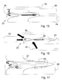
- FIG. 15 is a diagram of a device provided with a source of primary light and a source of secondary light, according to the invention.
- FIGS. 16 and 17 show several alternatives of a device including a secondary light source according to the invention.
- the different spectra show the absorption or the emission, versus the incident or emitted wavelength.
- the method essentially consists of coating a support prepared beforehand with a template matrix, and then of depositing on this matrix, the cyanine molecules in order to form J aggregate.
- a glass support of the borosilicate type forming a plate of about 3 cm by 1 cm is cleaned, for example by immersion in a so-called Piranha solution consisting of H 2 SO 4 and of H 2 O 2 , in a proportion of 2 to 1, at 120° C. for 10 minutes.
- Piranha solution consisting of H 2 SO 4 and of H 2 O 2 , in a proportion of 2 to 1, at 120° C. for 10 minutes.
- the support is rinsed with ultra-pure water and dried under a stream of nitrogen.
- the support is then activated by treatment with oxygen plasma, for 3 minutes. This plasma is generated between two capacitor plates, by inducing a radiofrequency current through the plates.
- the highly energetic particles of the plasma degrade the possible organic residues remaining on the support into volatile molecules which are evacuated.
- the support is then perfectly cleaned and ready for the following steps.
- a template matrix is made on the basis of dendrimers, i.e. macromolecules, each consisting of monomers which associate with each other according to an arborescent process around a plurifunctional core.
- the arborescent construction is carried out by repeating a same sequence of reactions until a new generation and an increasing number of identical branches are obtained at the end of each reaction cycle.
- a dendrimer example, a polyamido-amide of the fourth generation, designated as PAMAM G4 is illustrated in FIG. 1 .
- the dendrimers have the advantage of being monodisperse and of having strictly controlled structure, geometry and stoichiometry. Indeed, as the reaction scheme of their preparation is clearly defined, each of the molecules of a given dendrimer is identical with another. The number of functions, the charge density, the surface and the occupied volume, are known for a dendrimer molecule. The table hereafter gives a few examples of dendrimers as well as their properties.
- the support prepared during the preceding step is immersed for 18 hours in an ethanol solution of PAMAM G4 concentrated to 1.10 ⁇ 4 M.
- PAMAM G4 concentrated to 1.10 ⁇ 4 M.
- the reactions between the PAMAM and the support are of the acidobasic type between the amine functions of the PAMAM and the silanol groups of the glass, but other types of interactions (electrostatic interactions, Van der Waals bonds, metal-ligand type interactions, etc. . . . ) may also be at play, depending on the different selected supports, as this will be explained hereafter.
- other deposition techniques may be used in order to obtain a homogenous monolayer. Among these techniques, mention may be made of: “spin coating” or deposition on a rotating sample, printing, “spraying” or pulverization, etc.
- the support is rinsed with pure ethanol in order to remove the PAMAM molecules not bound to the support. Finally, the support is dried under a stream of nitrogen.
- the cyanine used for forming the J aggregate is [5,5′-diphenyl-dibenzoxazolo-N,N′-propylsulfonate]-9-ethyl trimethine cyanine (called Myline 1).
- Myline 1 The cyanines are sensitive to light, exposing them to light should absolutely be avoided, both during the preparation of the reagent and during the reaction.
- the cyanine is put into solution in acetone at a concentration of 7.10 ⁇ 4 M.
- the mixture is magnetically stirred for 2 hours in order to guarantee total solubilization of the reagent.
- the proposed cyanine is charged negatively.
- the latter in order to allow it to interact with the PAMAM deposited on the support, the latter is immersed beforehand in an acid solution, typically hydrochloric acid at a pH of 3.5 in order to protonate all the amines of the PAMAM.
- the thereby activated support is then immersed in the above cyanine solution.
- the immersion time is comprised between a few seconds and a few minutes, and will be discussed hereafter.
- the support is rinsed with pure acetone and dried under a stream of nitrogen.
- An assembly consisting of a support, in this case in glass, covered with a regular monolayer of dendrimers, of PAMAM according to the example and with a monolayer of J aggregates, is thereby obtained.
- the assembly obtained above, particularly the cyanine layer, is analyzed by means of a UV-visible spectrophotometer.
- the obtained spectrum with an immersion time of 12 minutes is shown in FIG. 4 b , to be compared with that of the Myline 1solution used as a reagent, illustrated in FIG. 4 a.
- FIG. 4 a shows three peaks for the reagent, at 479 nm, 506 nm, and 551 mm described in the literature as respectively corresponding to the absorption peaks of the dimmer, of the monomer and of the J aggregate of Myline 1.
- the spectrum of the Myline 1 layer deposited on the support shows that there is no longer any dimmer (absence of a peak at 479 nm) and almost no longer any monomer (a weak peak at 507 nm).
- the signal corresponding to the J aggregate is very intense, which means that the layer almost exclusively consists of J aggregates.
- the wavelength of the J aggregate peak obtained according to the above method and for reference samples obtained by the Langmuir-Blodgett technique are remarkably in agreement, thereby confirming the regularity and quality, i.e. the high organization and the large homogeneity of the produced J aggregate.
- the quality of the organization and of the homogeneity of the formed J aggregate is confirmed by comparing the fluorescence emission and absorption wavelengths of the assembly obtained above.
- the spectrum is shown in FIG. 5 .
- the absorption peak a appears at a wavelength of 549 nm, whereas the emission peak b appears at 554 nm. This small difference shows that the layer is homogenous and perfectly organized at a molecular level.
- FIG. 6 shows the changes in absorption for an assembly obtained according to the invention, with a glass support covered with PAMAMs of different generations G1, G4 and G6 respectively, for the spectra 10 , 11 and 12 . Between the different measurements, the samples are kept in darkness. The spectra indexed as a are obtained just after the reaction, whereas the spectra indexed as b were achieved 14 weeks later. It is observed that in the absence of light, the J aggregates obtained according to the method of the invention, remain remarkably organized, and even that the intensity of the peaks slightly increases. It may be believed that this effect is due to the removal of solvent traces still present just after the reaction.
- a glass support was covered with a polylysine layer.
- This polymer includes a large number of amine functions and its capacity of self-arranging the Myline 1 molecules into J aggregates may therefore be compared with that observed for PAMAM.
- the assembly formed by a glass support and a polylysine layer undergoes the treatment described in the previous paragraph relating to the formation of J aggregates.
- FIG. 7 illustrates the UV absorption spectra of a Myline 1 layer deposited under the following conditions:
- FIG. 7 shows that with a polylysine layer, the absorption peak corresponding to the J aggregate is poorly defined (between 530 and 544 nm), less intense and much wider that with a PAMAM layer.
- the spectrum d illustrates that the cyanine molecules are not stable on the polylysine layer and that they reorganize on this surface.
- this comparison proves that the dendrimer matrices, and in particular those functionalized with PAMAM, have an excellent capacity of self-arranging the cyanine molecules into stable and highly organized J aggregates and consequently with optical properties very close to the reference properties.
- a PAMAM layer is deposited according to the method described earlier as regards a glass support.
- PAMAM adheres with the gold layer essentially by the interactions between the peripheral primary amines of the PAMAM and the gold atoms of the surface. With the large number of these primary amines, very good adherence of PAMAM on the gold support may be obtained.
- an aqueous solvent the nature of the interactions between the PAMAM and gold is very different and essentially controlled by electrostatic attraction. Indeed, under these conditions, the peripheral amine groups tend to be protonated, positively charging the PAMAM.
- support may further be contemplated, such as silicon, mica, quartz, or metal oxides, notably, or even flexible supports of the polymer or polycarbonate type, it being essential that sufficient interactions may be established between the support and the layer of dendrimers and that these interactions be of a nature allowing generation of a monolayer of dendrimers on the support.
- One skilled in the art by means of simple experiments, will be able to establish other associations between supports and dendrimers, by varying the functional groups of the dendrimer or the experimental conditions for depositing the monolayer. It should also be noted that it is possible to have an intermediate adhesion layer between the support and the monolayer of dendrimers. An example of such an intermediate layer may be found in the article of M. Wells and R. M. Crooks, 3. Am. Chem. Soc. 1996, 118, 3988-3989.
- PAMAM poly(ethylene glycol)
- G3.5 G4.5, . . . , Gm.5, . . . with peripheral carboxyl (COOH) or carboxylate (COO ⁇ ) functions
- PAMAM G3.5 G4.5, . . . , Gm.5, . . . with peripheral carboxyl (COOH) or carboxylate (COO ⁇ ) functions
- PAMAM G3.5 G4.5
- Gm.5 peripheral carboxyl
- COO ⁇ carboxylate
- the essential characteristics which the molecule which forms the template matrix should have, is that its outer surface, i.e. the one forming the interface with the reaction medium when it is on the support, should be defined and regular.
- hyperbranch macromolecules comprising dendrimers but also hyperbranch polymers, i.e. molecules including a weakly organized, polymer type portion, and a well-defined dendrimer type portion.
- hyperbranch polymers may be suitable insofar that the polymer portion is used for binding this molecule to the support, the dendrimer portion then being at the interface with the dye molecules.
- hyperbranch polymers are supposed to be part of the family of dendrimers.
- cyanines i.e. cyanines, mero-cyanines and their derivatives
- cyanines i.e. cyanines, mero-cyanines and their derivatives
- the cyanine and the molecule forming the template matrix have to be selected depending on each other so that the cyanine interacts with the functional groups present at the periphery of the template matrix; for example this involves complementarity of the electric charges and similarity of the charge densities.
- a cationic type of cyanine may also self-arrange in order to form J aggregates on a negatively charged template matrix.
- An example of such a cyanine is illustrated in FIG. 10 while a negatively charged dendrimer may for example be a PAMAM of generation, Gm.5 with carboxylate peripheral functions.
- the solvents are involved in two steps of the reaction method.
- the dendrimer is dissolved in a first solvent.
- this first solvent preferably is an alcohol with a low molecular weight, notably methanol or ethanol.
- the dye is dissolved in a second solvent.
- the latter is acetone.
- the solution of cyanines used during the formation of J aggregates gives better conversion of the cyanine molecules into J aggregates if the cyanine concentration is sufficient, i.e. close to saturation, so as to allow J aggregate kernels to be formed in the solution, which will act as germs in the subsequent growth process of the J aggregate.
- the value of the saturation threshold of course depends on the solvent used and on the nature of the relevant cyanine. With acetone as a solvent and cyanine Myline 1, it is therefore desirable that the concentration be equal to or larger than 7.10 ⁇ 5 M.
- the step for forming J aggregates was conducted by setting the cyanine solution to different temperatures, i.e. to room temperature (22° C.), 40° C. and 55° C. These different tests are reproduced with a template matrix made on the basis of PAMAM G4 and PAMAM G6.
- the obtained absorption spectra are illustrated in FIGS. 11 a and 11 b , for PAMAM G4 and PAMAM G6, respectively.
- the curves a , b , c correspond to the temperatures, 22, 40 and 55° C.
- the influence of the immersion time of the support covered with the template matrix in the cyanine solution during the step for forming J aggregates was also explored. Times varying from 15 seconds to 12 minutes were tested, with a gold support covered with a layer of PAMAM G4, acidified and immersed in an acetone solution containing Myline 1 at 7.10 ⁇ 4 M.
- the obtained spectra are illustrated in FIG. 12 .
- the spectra a, b, c, d, e, f, g, h and i correspond to times of 15, 30, 45, 60, 90, 180 seconds, 6, 9 and 12 minutes, respectively. They show that a peak corresponding to the formation of J aggregates may already be observed after only 15 seconds. Maximum absorption is attained for an immersion time of 3 minutes. On the other hand, the smaller peak width at half-height is obtained for a time of 12 minutes.
- J aggregates As mentioned earlier, one of the properties of the J aggregates is to allow an exciton or an electron to circulate extremely rapidly and almost without any loss of energy. Thus, if J aggregates of cyanines are excited, all the cyanine molecules will emit resonance fluorescence with strong intensity.
- the present invention is based on the fact that, if an electron acceptor molecule is present in the environment of the J aggregate, the delocalized excitons in the J aggregate will be rapidly captured by the acceptor which will transform them into electron/hole pairs, which has the consequence of extinguishing the emission fluorescence.
- J aggregates of Myline 1 are prepared according to the method described above, on glass supports covered with a template matrix of PAMAM G4. The obtained assembly is then immersed for 1 hour in aqueous solutions of paraquat, at different concentrations. Next, the J aggregates are excited with a 510 nm wavelength source and the fluorescence emission spectra illustrated in FIG. 13 are obtained. They show the emission intensity in an arbitrary unit depending on the wavelength, for:
- d a sample having been soaked in a 1.10 ⁇ 6 M paraquat solution.
- an energy acceptor molecule In extension to what was mentioned above concerning the paraquat, the direct integration of an energy acceptor molecule into the actual interior of the J aggregate may be contemplated.
- a luminescent energy acceptor By selecting a luminescent energy acceptor, the absorption spectrum of which covers at least partly, the emission spectrum of the aggregate, this acceptor will collect with a certain yield, the excitation energy of the aggregate and will re-emit at its own emission wavelength.
- such an acceptor which may be suitable for being incorporated into an aggregate of Myline 1 molecules, may be as illustrated in FIG. 14 .
- Such a molecule has the properties required for the desired energy transfer (maximum absorption around 550 nm, emission around 600 nm).
- the energy acceptor molecules are dissolved in the stock solution of cyanines used for forming the J aggregates.
- This method for using J aggregates may notably find a particularly interesting application in devices including waveguides or other optical components. Indeed, it may be desirable to integrate into such a device a light source capable of injecting a light wave into the waveguide of said device. Such integration is made possible by means of the method according to the invention.
- the thereby obtained device is illustrated in FIG. 15 .
- a waveguide 24 for example in Ta 2 O 5 , is conventionally made on a glass substrate 23 .
- a dendrimer layer followed by a J aggregate layer, into which energy acceptor and luminescent molecules have been integrated are then deposited on the waveguide.
- a secondary light source 28 is covered by a separating transparent layer 26 , for example in glass.
- a primary light source 30 is made on the transparent layer 26 facing the source of secondary light 28 .
- the separating layer may be a transparent medium such as air.
- the energy acceptor molecules are capable of collecting the received light, at a first wavelength, from the primary source 30 and of re-emitting it at a second wavelength different from the first, into the waveguide 24 .
- the emission at the second wavelength may either be spontaneous, or stimulated.
- laser effect occurs when the excitation at the first wavelength is sufficiently intense to cause an inversion of population of the energy acceptors, which means that more than 50% of the energy acceptors are excited at any moment.
- the emission wavelength of the energy acceptor be sufficiently distant from the absorption one of the J aggregates, in order to prevent the light emitted by the acceptors from being absorbed by the aggregate instead of being conducted through the waveguide.
- the wavelengths are for example separated by at least 20 nm, particularly from about 50 to 70 nm.
- This secondary source 28 is intended to be excited by a primary light source 30 which may be positioned in several ways, as described in detail hereafter.
- the assembly formed by the waveguide 24 and the secondary light source 28 is integrated inside a device 23 .
- the secondary source 28 is covered with a transparent separator 26 , for example made in glass, the primary source 30 being directly positioned on the separator 26 .
- This primary source 30 may be a LED, an OLED or even another known light source.
- the assembly formed by the waveguide 24 and by the secondary light source 28 forms the upper layer of a device 23 .
- the primary light source 30 is located at a distance from the device and may be indifferently positioned relatively to the secondary source, as shown by the different illustrated positions, as long as the light which it emits reaches the secondary source, including through the substrate and the waveguide 24 of the device 23 .
- FIG. 17 proposes different alternative positions of the secondary light source 28 relatively to the waveguide 24 .
- the profile of the transmission mode of the waveguide is illustrated in 32 .
- the secondary source 28 may be placed anywhere inside the mode profile. In other words, it should be located in the region where the electromagnetic field of the guided wave is increased by the waveguide. It is also possible to combine several secondary sources, located at different positions, these different sources being able to absorb and/or re-emit at different wavelengths, depending on the application and the selected material.
- the luminescent acceptor is localized in a specific location of the J aggregate instead of being distributed therein in a homogenous way.
- the area including the acceptor will absorb the energy moving in the aggregate and only this area will emit light.
Landscapes
- Chemical & Material Sciences (AREA)
- Physics & Mathematics (AREA)
- Health & Medical Sciences (AREA)
- Organic Chemistry (AREA)
- Life Sciences & Earth Sciences (AREA)
- General Physics & Mathematics (AREA)
- Chemical Kinetics & Catalysis (AREA)
- Optics & Photonics (AREA)
- Analytical Chemistry (AREA)
- Polymers & Plastics (AREA)
- Nuclear Medicine, Radiotherapy & Molecular Imaging (AREA)
- Engineering & Computer Science (AREA)
- Wood Science & Technology (AREA)
- Materials Engineering (AREA)
- Medicinal Chemistry (AREA)
- Biochemistry (AREA)
- General Health & Medical Sciences (AREA)
- Immunology (AREA)
- Pathology (AREA)
- Investigating, Analyzing Materials By Fluorescence Or Luminescence (AREA)
- Optical Integrated Circuits (AREA)
- Application Of Or Painting With Fluid Materials (AREA)
- Indole Compounds (AREA)
Applications Claiming Priority (4)
| Application Number | Priority Date | Filing Date | Title |
|---|---|---|---|
| CH01838/05A CH703675B1 (fr) | 2005-11-16 | 2005-11-16 | Procédé de réalisation d'agrégats J. |
| CH1838/05 | 2005-11-16 | ||
| CH0183805 | 2005-11-16 | ||
| PCT/EP2006/068340 WO2007057356A2 (fr) | 2005-11-16 | 2006-11-10 | Procede de realisation d'agregats j |
Publications (2)
| Publication Number | Publication Date |
|---|---|
| US20080279500A1 US20080279500A1 (en) | 2008-11-13 |
| US8088929B2 true US8088929B2 (en) | 2012-01-03 |
Family
ID=37946143
Family Applications (1)
| Application Number | Title | Priority Date | Filing Date |
|---|---|---|---|
| US12/094,038 Active 2028-07-26 US8088929B2 (en) | 2005-11-16 | 2006-11-10 | Method for producing J aggregates |
Country Status (5)
| Country | Link |
|---|---|
| US (1) | US8088929B2 (de) |
| EP (1) | EP1788036B1 (de) |
| AT (1) | ATE526368T1 (de) |
| CH (1) | CH703675B1 (de) |
| WO (1) | WO2007057356A2 (de) |
Families Citing this family (2)
| Publication number | Priority date | Publication date | Assignee | Title |
|---|---|---|---|---|
| ATE477305T1 (de) | 2007-08-23 | 2010-08-15 | Suisse Electronique Microtech | Zusammensetzung, die j-aggregate umfasst |
| EP2684839A1 (de) | 2012-07-13 | 2014-01-15 | CSEM Centre Suisse d'Electronique et de Microtechnique SA - Recherche et Développement | Mesoporöse Schicht mit J-Aggregaten |
Citations (8)
| Publication number | Priority date | Publication date | Assignee | Title |
|---|---|---|---|---|
| DE19855180A1 (de) * | 1998-11-30 | 2000-05-31 | Metabion Gmbh Ges Fuer Angewan | in situ-Hybridisierungsverfahren |
| EP1081557A1 (de) | 1999-09-03 | 2001-03-07 | Sharp Kabushiki Kaisha | Elektrophotographischer Photorezeptor, Beschichtungsflüssigkeit für photoempfindliche Schichten, Herstellungsverfahren und elektrophotographischer Apparat |
| EP1085315A1 (de) | 1999-09-15 | 2001-03-21 | CSEM Centre Suisse d'Electronique et de Microtechnique SA | Integrierter optischer Sensor |
| US20040023248A1 (en) * | 2001-12-07 | 2004-02-05 | Whitehead Institiute For Biomedical Research | Methods and reagents for improving nucleic acid detection |
| US20050191643A1 (en) * | 2003-08-11 | 2005-09-01 | Rosaria Haugland | Cyanine compounds and their application as quenching compounds |
| US6977178B2 (en) * | 2000-09-06 | 2005-12-20 | Transnetyx, Inc. | System and method for transgenic and targeted mutagenesis screening |
| US7261875B2 (en) * | 2001-12-21 | 2007-08-28 | Board Of Regents, The University Of Texas System | Dendritic poly (amino acid) carriers and methods of use |
| US7824617B2 (en) * | 2007-08-23 | 2010-11-02 | CSEM Centre Suisse d'Electronique et de Microtechnique SA-Recherche et Development | Assembly comprising J aggregates |
-
2005
- 2005-11-16 CH CH01838/05A patent/CH703675B1/fr not_active IP Right Cessation
- 2005-12-07 AT AT05111790T patent/ATE526368T1/de not_active IP Right Cessation
- 2005-12-07 EP EP05111790A patent/EP1788036B1/de not_active Expired - Lifetime
-
2006
- 2006-11-10 WO PCT/EP2006/068340 patent/WO2007057356A2/fr not_active Ceased
- 2006-11-10 US US12/094,038 patent/US8088929B2/en active Active
Patent Citations (8)
| Publication number | Priority date | Publication date | Assignee | Title |
|---|---|---|---|---|
| DE19855180A1 (de) * | 1998-11-30 | 2000-05-31 | Metabion Gmbh Ges Fuer Angewan | in situ-Hybridisierungsverfahren |
| EP1081557A1 (de) | 1999-09-03 | 2001-03-07 | Sharp Kabushiki Kaisha | Elektrophotographischer Photorezeptor, Beschichtungsflüssigkeit für photoempfindliche Schichten, Herstellungsverfahren und elektrophotographischer Apparat |
| EP1085315A1 (de) | 1999-09-15 | 2001-03-21 | CSEM Centre Suisse d'Electronique et de Microtechnique SA | Integrierter optischer Sensor |
| US6977178B2 (en) * | 2000-09-06 | 2005-12-20 | Transnetyx, Inc. | System and method for transgenic and targeted mutagenesis screening |
| US20040023248A1 (en) * | 2001-12-07 | 2004-02-05 | Whitehead Institiute For Biomedical Research | Methods and reagents for improving nucleic acid detection |
| US7261875B2 (en) * | 2001-12-21 | 2007-08-28 | Board Of Regents, The University Of Texas System | Dendritic poly (amino acid) carriers and methods of use |
| US20050191643A1 (en) * | 2003-08-11 | 2005-09-01 | Rosaria Haugland | Cyanine compounds and their application as quenching compounds |
| US7824617B2 (en) * | 2007-08-23 | 2010-11-02 | CSEM Centre Suisse d'Electronique et de Microtechnique SA-Recherche et Development | Assembly comprising J aggregates |
Non-Patent Citations (13)
| Title |
|---|
| Bumb, A. et al., "Preparation and Characterization of a Magnetic and Optical Dual-Modality Molecular Probe", Nanotechnology, 21(17), 175704 (9pp), 2010. * |
| D.M. Sturmer: "Syntheses and Properties of Cyanine and Related Dyes" published in the book "Chemistry of Heterocyclic Compounds: Special Topics" edited by A. Weissberger et al., 1977 (Wiley Interscience, New York) vol. 30, pp. 441-601. |
| Esfand, Roseita et al., "Poly(amidoamine) (PAMAM) Dendrimers: From Biomimicry to Drug Delivery and Biomedical Applications", DDT, 6(8), 427-436, Apr. 2001. * |
| H. Kuhn et al. "Chromophore Coupling Effects" published in a book entitled "J-aggregates" by T. Kobayashi, pp. 1-40, ISBN 981-02-2737-X. |
| H. Tokuhisa et al: "Preparation and Characterization of Dendrimer Monolayers and Dendrimer-Alkanethiol Mixed Monolayers Adsorbed to Gold" Journal of the American Chemical Society, vol. 120, 1998, pp. 4492-4501, XP002417618. |
| Kometani, Noritsugu et al., Luminescence Properties of the Mixed J-Aggregate of Two Kinds of Cyanine Dyes in Layer-by Layer Alternate Assemblies:, Journal of Physical Chemistry B, 104(41), 9630-9637, 2000. * |
| M. Losson: "Self-organizing properties of dendrimers and potential applications; These pur l'obtention du titre de Docteur es Sciences" Oct. 24, 2005, Universite de Neuchatel; Faculte des Sciences, Neuchatel, XP002417620, the whole document. |
| M. Wells et al: "Interactions between Organized, Surface-Confined Monolayers and Vapor-Phase Probe Molecules. 10. Preparation and Properties of Chemically Sensitive Dendrimer Surfaces" Journal of American Chemical Society, vol. 118, No. 16, 1996, pp. 3988-3989. |
| Place, Ileana. et al., "Layered Nanocomposites of Aggregated Dyes and Inorganic Scaffolding", J. Phys. Chem. A, 107(18), 3169-3177, 2003. * |
| R. Steiger et al.: "Physical-Chemical Properties of Organized Sensitizer Molecules" Journal of Imaging Science, vol. 32, 1988, pp. 64-81, XP008074432. |
| Steiger, Rolf et al., "J-Aggregation of Cyanine Dyes by Self-Assembly", Colloids and Surfaces B: Biointerfaces, 74, 484-491, 2009. * |
| Talanov , Vladimir S. et al., "Dendrimers for Dual Imaging Modalities: Combining Magnetic Resonance and Optical Fluorescent Imaging", 37th ACS Meeting, Middle Atlantic Regional Meting (May 22-25, 2005), Abstract No. 409. * |
| Talanov, Vladimir S. et al., "Dendrimer-Based Nanoprobe for Dual Modality Magnetic Resonance and Fluorescence Imaging", Nano Letters, 6(7), 1459-1463, 2006. * |
Also Published As
| Publication number | Publication date |
|---|---|
| US20080279500A1 (en) | 2008-11-13 |
| CH703675B1 (fr) | 2012-03-15 |
| WO2007057356A3 (fr) | 2007-08-23 |
| EP1788036A1 (de) | 2007-05-23 |
| WO2007057356A2 (fr) | 2007-05-24 |
| EP1788036B1 (de) | 2011-09-28 |
| ATE526368T1 (de) | 2011-10-15 |
Similar Documents
| Publication | Publication Date | Title |
|---|---|---|
| Tao et al. | Resonance-induced stimuli-responsive capacity modulation of organic ultralong room temperature phosphorescence | |
| Weil et al. | Polyphenylene dendrimers with different fluorescent chromophores asymmetrically distributed at the periphery | |
| Tamaki et al. | Nanoparticle formation of vanadyl phthalocyanine by laser ablation of its crystalline powder in a poor solvent | |
| Micali et al. | From fractal to nanorod porphyrin J-aggregates. Concentration-induced tuning of the aggregate size | |
| Nakamura et al. | Directly meso− meso linked porphyrin rings: Synthesis, characterization, and efficient excitation energy hopping | |
| Yeow et al. | The dynamics of electronic energy transfer in novel multiporphyrin functionalized dendrimers: a time-resolved fluorescence anisotropy study | |
| Galeotti et al. | Self-functionalizing polymer film surfaces assisted by specific polystyrene end-tagging | |
| CN106093001A (zh) | 聚多巴胺‑银粒子‑聚多巴胺型表面增强拉曼光谱衬底及其制备方法 | |
| Marinescu | Synthesis and nonlinear optical studies on organic compounds in laser-deposited films | |
| US8088929B2 (en) | Method for producing J aggregates | |
| Barman et al. | Bioinspired carbonized polymer microspheres for full-color whispering gallery mode emission for white light emission, unclonable anticounterfeiting, and chemical sensing applications | |
| US20120251396A1 (en) | Device for sorting carbon nanotubes | |
| Cavinato et al. | Blue‐Emitting Boron‐and Nitrogen‐Doped Carbon Dots for White Light‐Emitting Electrochemical Cells | |
| Okamoto et al. | Shape‐Dependent Kinetics of Halide Vacancy Filling in Organolead Halide Perovskites | |
| Pekdemir et al. | Modulating the kinetics of nanoparticle adsorption for simple and high‐yield fabrication of plasmonic heterostructures as SERS substrates | |
| JP2007296823A (ja) | パターン形成用モールド,パターン形成用モールドの離型処理方法および離型剤濃度の評価方法 | |
| Lupo et al. | Optical recognition of n-butylammonium and 1, 5-pentanediammonium picrates by a calix [5] arene monolayer covalently assembled on silica substrates | |
| CN118599250A (zh) | 一种光敏复合材料、和一种上转换纳米粒子辅助的近红外激光三维直写方法及装置 | |
| CN113113546A (zh) | 一种光电晶体管及其制备方法 | |
| Märker et al. | Simultaneous positive and negative optical patterning with dye-sensitized CdSe quantum dots | |
| Zhou et al. | Development of Spiropyran Immobilization and Characterization Protocols for Reversible Photopatterning of SiO2 Surfaces | |
| Chen et al. | Matrix‐assisted laser desorption/ionization mass spectrometry using a visible laser | |
| CN101782708B (zh) | 基于氧化锌纳米线的全光开关的制备方法及全光开关 | |
| US7824617B2 (en) | Assembly comprising J aggregates | |
| Halterman et al. | Cucurbit [7] uril disrupts aggregate formation between rhodamine B dyes covalently attached to glass substrates |
Legal Events
| Date | Code | Title | Description |
|---|---|---|---|
| AS | Assignment |
Owner name: CSEM CENTRE SUISSE D'ELECTRONIQUE ET DE MICROTECHN Free format text: ASSIGNMENT OF ASSIGNORS INTEREST;ASSIGNORS:LOSSON, MYRIAM;PUGIN, RAPHAWL;STEIGER, ROLF;AND OTHERS;REEL/FRAME:021025/0136;SIGNING DATES FROM 20080509 TO 20080519 Owner name: CSEM CENTRE SUISSE D'ELECTRONIQUE ET DE MICROTECHN Free format text: ASSIGNMENT OF ASSIGNORS INTEREST;ASSIGNORS:LOSSON, MYRIAM;PUGIN, RAPHAWL;STEIGER, ROLF;AND OTHERS;SIGNING DATES FROM 20080509 TO 20080519;REEL/FRAME:021025/0136 |
|
| STCF | Information on status: patent grant |
Free format text: PATENTED CASE |
|
| FEPP | Fee payment procedure |
Free format text: PAYOR NUMBER ASSIGNED (ORIGINAL EVENT CODE: ASPN); ENTITY STATUS OF PATENT OWNER: SMALL ENTITY |
|
| FPAY | Fee payment |
Year of fee payment: 4 |
|
| MAFP | Maintenance fee payment |
Free format text: PAYMENT OF MAINTENANCE FEE, 8TH YR, SMALL ENTITY (ORIGINAL EVENT CODE: M2552); ENTITY STATUS OF PATENT OWNER: SMALL ENTITY Year of fee payment: 8 |
|
| FEPP | Fee payment procedure |
Free format text: 11.5 YR SURCHARGE- LATE PMT W/IN 6 MO, SMALL ENTITY (ORIGINAL EVENT CODE: M2556); ENTITY STATUS OF PATENT OWNER: SMALL ENTITY |
|
| MAFP | Maintenance fee payment |
Free format text: PAYMENT OF MAINTENANCE FEE, 12TH YR, SMALL ENTITY (ORIGINAL EVENT CODE: M2553); ENTITY STATUS OF PATENT OWNER: SMALL ENTITY Year of fee payment: 12 |