US8074674B2 - Block for chemically dosing a stream of fluid and an apparatus for housing the block - Google Patents
Block for chemically dosing a stream of fluid and an apparatus for housing the block Download PDFInfo
- Publication number
- US8074674B2 US8074674B2 US12/444,310 US44431007A US8074674B2 US 8074674 B2 US8074674 B2 US 8074674B2 US 44431007 A US44431007 A US 44431007A US 8074674 B2 US8074674 B2 US 8074674B2
- Authority
- US
- United States
- Prior art keywords
- block
- chamber
- fluid
- stream
- bypass
- Prior art date
- Legal status (The legal status is an assumption and is not a legal conclusion. Google has not performed a legal analysis and makes no representation as to the accuracy of the status listed.)
- Active
Links
Images


Classifications
-
- A—HUMAN NECESSITIES
- A62—LIFE-SAVING; FIRE-FIGHTING
- A62C—FIRE-FIGHTING
- A62C5/00—Making of fire-extinguishing materials immediately before use
- A62C5/02—Making of fire-extinguishing materials immediately before use of foam
-
- B—PERFORMING OPERATIONS; TRANSPORTING
- B01—PHYSICAL OR CHEMICAL PROCESSES OR APPARATUS IN GENERAL
- B01F—MIXING, e.g. DISSOLVING, EMULSIFYING OR DISPERSING
- B01F21/00—Dissolving
- B01F21/20—Dissolving using flow mixing
- B01F21/22—Dissolving using flow mixing using additional holders in conduits, containers or pools for keeping the solid material in place, e.g. supports or receptacles
-
- C—CHEMISTRY; METALLURGY
- C02—TREATMENT OF WATER, WASTE WATER, SEWAGE, OR SLUDGE
- C02F—TREATMENT OF WATER, WASTE WATER, SEWAGE, OR SLUDGE
- C02F1/00—Treatment of water, waste water, or sewage
- C02F1/68—Treatment of water, waste water, or sewage by addition of specified substances, e.g. trace elements, for ameliorating potable water
- C02F1/685—Devices for dosing the additives
- C02F1/688—Devices in which the water progressively dissolves a solid compound
-
- C—CHEMISTRY; METALLURGY
- C02—TREATMENT OF WATER, WASTE WATER, SEWAGE, OR SLUDGE
- C02F—TREATMENT OF WATER, WASTE WATER, SEWAGE, OR SLUDGE
- C02F2303/00—Specific treatment goals
- C02F2303/08—Corrosion inhibition
-
- C—CHEMISTRY; METALLURGY
- C02—TREATMENT OF WATER, WASTE WATER, SEWAGE, OR SLUDGE
- C02F—TREATMENT OF WATER, WASTE WATER, SEWAGE, OR SLUDGE
- C02F2303/00—Specific treatment goals
- C02F2303/12—Prevention of foaming
-
- Y—GENERAL TAGGING OF NEW TECHNOLOGICAL DEVELOPMENTS; GENERAL TAGGING OF CROSS-SECTIONAL TECHNOLOGIES SPANNING OVER SEVERAL SECTIONS OF THE IPC; TECHNICAL SUBJECTS COVERED BY FORMER USPC CROSS-REFERENCE ART COLLECTIONS [XRACs] AND DIGESTS
- Y10—TECHNICAL SUBJECTS COVERED BY FORMER USPC
- Y10T—TECHNICAL SUBJECTS COVERED BY FORMER US CLASSIFICATION
- Y10T137/00—Fluid handling
- Y10T137/4891—With holder for solid, flaky or pulverized material to be dissolved or entrained
Definitions
- the present invention relates to chemically dosing a stream of fluid.
- the present invention also relates to an apparatus used in chemically dosing a stream of fluid.
- fire retardant foam may sometimes be employed to smother a fire, particularly in the case of electrical fires or flammable liquid fires (such as oil fires) in which water is not a suitable fire extinguishing material.
- the chemical components of the fire retardant foam are typically dissolved or suspended in water, the foam readily forming as the water and chemicals are sprayed out of a nozzle.
- the primary component of the fire retardant foam is a surfactant, which readily foams when sprayed out of the nozzle.
- the concentration of the surfactant in the water is typically less than 1%.
- Some types of surfactants employed include synthetic surfactants such as alpha-olefin sulfonates, perfluorooctane sulfonate, perfluorooactanoic acid and protein based surfactants.
- Other components of fire retardant foams may include organic solvents such as trimethyltrimethylene glycol and hexylene glycol, foam stabilisers such as lauryl alcohol and corrosion inhibitors.
- the foam components and water are held in a compressed volume, similar to the arrangement in an aerosol can.
- the compressed gas which compresses the water and foam components escapes through a valve, causing the application of a pressure on the water, driving it out of the cylinder through a nozzle. As this occurs, the foaming components form the foam.
- a foam tank containing water and the foam components is provided on board the fire truck.
- the pressure required to drive the water carrying the foam components through a nozzle to form the foam is provided by the fire truck's onboard pump.
- solid blocks containing surfactants supported in a polyethylene glycol matrix have been employed to create fire retardant foams by placing the solid blocks in the path of a stream of water.
- the block is housed in a chamber at some point between a water source and a nozzle.
- the block including the surfactant dissolves and/or erodes into the fluid.
- the rate of loss of material from the block is directly proportional to the exposed surface area of the chemical block.
- the fluid, now containing surfactant may flow through a nozzle to create the fire retardant foam.
- cleaning apparatus for cleaning cars and other vehicles may have accessories which enable a liquid detergent concentrate to be added to a stream of water to assist in the cleaning process.
- the detergent is added by flowing the water past an opening to a volume of the detergent through the opening and, which draws some of the detergent out into the water under a “venturi” effect.
- a block for chemically dosing a stream of fluid flowing past the block comprising at least one surface for the fluid to flow past to dissolve and/or erode the block, wherein the block is shaped to enable the at least one surface to be dissolved and/or eroded without a substantial change in the area of the at least one surface.
- the at least one surface is substantially flat.
- the at least one substantially flat surface of the block is of any suitable shape, such as rectangular, triangular, circular or hexagonal for example, however, preferably it is rectangular.
- the block comprises two substantially flat surfaces, parallel to one another.
- both substantially flat surfaces are for flowing the stream of fluid to flow past.
- the block comprises opposing side walls extending between the two substantially flat surfaces.
- the block comprises opposing end walls extending between the two substantially flat surfaces and between the opposing side walls.
- the block is of any suitable shape provided that as the at least one substantially flat surface dissolves/erodes, the effective surface area which is dissolving/eroding does not substantially change.
- the block is a rectangular prism.
- the surface(s) for the fluid to flow past is an outer surface(s) of the rectangular prism.
- the block is a hollow rectangular prism and the at least one surface for the fluid to flow past is the inner surfaces of the hollow rectangular prism.
- composition of the block is dependent on the application for which it is to be used.
- the block consists of one or more active ingredients and a solid carrier for carrying the one or more active ingredients.
- the active ingredients are evenly distributed throughout the solid carrier matrix.
- the solid carrier is soluble in water.
- a suitable solid carrier is polyethylene glycol.
- the solid carrier may be any other suitable substance for carrying the active ingredients.
- the polyethylene glycol has an average molecular weight of between 1000 and 8000 MW.
- the one or more active ingredients comprise at least one surfactant for a fire fighting application.
- the surfactants are for forming a fire retardant foam.
- the one or more active ingredients comprise a foam stabiliser.
- the one or more active ingredients comprise a corrosion inhibitor.
- the one or more active ingredients comprise at least one detergent for a cleaning application.
- one or more active ingredients comprise any one or more compounds selected from the group consisting of fertilisers, pesticides, insecticides and herbicides for an agricultural or a gardening application.
- an apparatus for housing a block for chemically dosing a stream of fluid flowing past the block, by dissolution and/or erosion of the block comprising a chamber for the block to reside in, the chamber having an inlet and an outlet to enable the stream of fluid to flow therethrough.
- the block is the block according to the first aspect of the present invention.
- the chamber is arranged to provide a substantially constant concentration of chemicals in the fluid at its outlet for a given flowrate when the block resides therein.
- the shape of the chamber is generally the same as the shape of the block.
- the chamber is rectangular in shape.
- the chamber is preferably arranged to house the block whereby, in use, only the at least one surface of the block which does not substantially change in area as it dissolves and/or erodes is exposed to the flow of fluid.
- the chamber is shaped to enable the block to reside therein with its opposing side walls snugly abutting the side walls of the chamber.
- the chamber is shaped so that the opposing side walls of the block cannot dissolve and/or erode in use, when the block resides in the chamber.
- the chamber is arranged so that, in use, fluid entering and exiting the chamber does not significantly dissolve and/or erode the opposing end walls of the rectangular block.
- the chamber is shaped to enable the at least one surface of the block to be positioned approximately perpendicular to the side walls of the chamber when the block resides therein.
- the chamber is preferably shaped to provide a space next to the at least one surface of the block for the stream of fluid to flow through when the block resides therein.
- the chamber is shaped to provide spaces next to the respective surfaces of the block when it resides therein for the stream of fluid to flow through.
- the apparatus also comprise a regulating mechanism, which regulates flow of the fluid to enable flow to one or both of the spaces next to the surfaces respectively in order to vary the concentration of the chemicals in the dosed fluid exiting the apparatus.
- the space(s) may be above, below or beside the at least one surface(s) of the block.
- the apparatus also comprises a retaining mechanism for holding the block in position in the chamber.
- the retaining mechanism comprises an opposing pair of ridges formed on the side walls of the chamber for engaging corresponding grooves formed in the opposing side walls of the block.
- the retaining mechanism comprises an opposing pair of grooves formed in the side walls of the chamber for receiving corresponding ridges formed on the opposing side walls of the block.
- the apparatus also comprises an inlet and an outlet.
- the inlet and the outlet of the chamber are fluidly connected to the inlet and the outlet of the apparatus respectively.
- the apparatus also comprises a bypass for allowing some or all of the fluid stream to bypass the chamber.
- the bypass is fluidly connected to the inlet and the outlet of the apparatus.
- the apparatus also comprises a baffle wall for separating the chamber from the bypass.
- the baffle wall forms one side of the chamber.
- the apparatus also comprises a bypass regulator for regulating the flow of fluid through the bypass.
- any fluid flowing through the bypass is used to dilute the fluid from the outlet of the chamber which has been chemically dosed by the block.
- the apparatus also comprises a mixing well, located prior to the outlet of the apparatus for mixing fluid from the bypass and the chemically dosed fluid from the outlet of the chamber.
- the bypass regulator may be any suitable mechanism, but preferably is a two-way valve.
- the bypass regulator may be infinitely or discretely variable from zero flow through the bypass to 100% flow through the bypass.
- the apparatus also comprises a removable end cap for access to the chamber.
- the removable end cap may be readily removed to enable the block to be inserted or removed and a new block inserted.
- the apparatus also comprises a non-return valve located in the outlet of the chamber.
- the non-return valve prevents any flow of fluid from the bypass into the chamber through the chamber's outlet.
- the apparatus may be hand held or mounted to a skid, or fixed permanently to a truck (or other vehicle) or the ground.
- the apparatus is manufactured from any suitable plastic or metallic material or a combination thereof.
- FIG. 1 is a side view of an apparatus for housing a block for chemically dosing a stream of fluid according to an embodiment of the present invention, with a bypass regulator of the apparatus arranged to allow the fluid to flow through a chamber in which the block resides;
- FIG. 2 is a side view of the apparatus of FIG. 1 , with the bypass regulator arranged to bypass the fluid past the chamber;
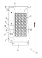
- FIGS. 3 and 4 are side views of an apparatus for housing a block for chemically dosing a stream of fluid according to another embodiment of the present invention.
- FIGS. 5 and 6 are graphs comparing the performance of a conventional block for chemically dosing a stream of fluid against a block according to an embodiment of the invention.
- FIGS. 1 and 2 an apparatus 10 for housing a block 11 for chemically dosing a stream of fluid according to an embodiment of the present invention is shown.
- the stream of fluid flows past the block 11 (by flowing through the apparatus 10 ), the block 11 chemically dosing the stream of fluid by dissolving and/or eroding into the fluid.
- the block 11 comprises at least one surface 30 for the fluid to flow past to dissolve and/or erode the block 11 , wherein the block 11 is shaped to enable the at least one surface 30 to be dissolved and/or eroded without a substantial change in the area of the at least one surface 30 . Because the surface area of the block 11 which dissolves and/or erodes does not change, this enables the block 11 to provide a constant rate of chemical dosing to the fluid for a given flowrate of the fluid past the surface 30 of the block 11 for a substantial portion of the working life of the block 11 .
- the at least one surface 30 of the block 11 shown in FIGS. 1 and 2 comprises two substantially flat surfaces, parallel to one another, in which case the block 11 , in use, may be arranged to enable the stream of fluid to flow over both substantially flat surfaces.
- the block 11 also comprises opposing side walls 31 extending between the two substantially flat surfaces 30 .
- the block 11 may have only one substantially flat surface for flowing the fluid over.
- the substantially flat surface(s) 30 enable the block 11 to provide a constant rate of chemical dosing to the fluid for a given flowrate because as the block 11 dissolves and/or erodes, the effective surface area of the block 11 which is dissolving/eroding does not substantially change.
- the flat surface(s) 30 of the block 11 may be of any suitable shape, such as rectangular, triangular, circular or hexagonal for example, however, preferably it is rectangular.
- the block 11 itself may be of any suitable shape provided that as the at least one surface dissolves/erodes, the effective surface area which is dissolving/eroding is not substantially reduced.
- the block 11 may be of any suitable shape, preferably it is a rectangular prism.
- the composition of the block 11 is dependent on the application for which it is to be used.
- the block 11 may consist of surfactants for fire fighting applications, detergents for cleaning applications or fertilisers, pesticides, insecticides or herbicides for agricultural or gardening applications or any other one or more active ingredients as desired.
- the block 11 also consists of a solid carrier for carrying the one or more active ingredients of the block 11 , which in the case of the fire fighting application is the surfactant(s).
- the surfactant(s) or other active ingredients are evenly distributed throughout the solid carrier matrix.
- a suitable solid carrier is polyethylene glycol having an average molecular weight of between 1000 and 8000 MW.
- any other suitable substance may be employed as the solid carrier, which is preferably water soluble.
- the one or more active ingredients may also comprise a foam stabiliser(s) and may also comprise a corrosion inhibitor(s).
- the stream of fluid is dosed with the surfactant(s) and any other chemicals present in the block 11 , as the block 11 , including the solid carrier, dissolves and/or erodes into the fluid flowing over the surfaces 30 of the block 11 .
- the apparatus 10 comprises a chamber 12 for the block 11 to reside in.
- the chamber 12 has an inlet 13 and an outlet 14 to enable the stream of fluid to flow through the chamber 12 .
- the chamber 12 houses the block 11 such that, in use, only the surfaces 30 of the block 11 which do not substantially change in area as they dissolve and/or erode are exposed to the flow of fluid.
- the chamber 12 is shaped so that the block 11 resides therein with its opposing side walls 31 snugly abutting the side walls of the chamber 12 .
- the substantially flat surfaces 30 of the block 11 are approximately perpendicular to the side walls of the chamber 12 .
- the snug abutment of the opposing side walls 31 of the block 11 against the side walls of the chamber 12 prevent the opposing side walls 31 from being eroded and/or dissolved because fluid cannot flow past the opposing side walls 31 . If this were to occur then it could cause a reduction in the surface area of the substantially flat surfaces 30 of the block 11 , which in turn would reduce the rate of dosing by the block 11 .
- the chamber 12 is also shaped to provide a space next to the substantially flat surfaces 30 of the block 11 for the stream of fluid to flow through and past the surfaces 30 when the block 11 resides therein.
- the apparatus 10 is also provided with a suitable retaining mechanism.
- the retaining mechanism comprises an opposing pair of ridges formed on the side walls of the chamber 12 .
- the opposing pair of ridges are shaped to engage corresponding grooves formed in the opposing side walls 31 of the block 11 .
- the retaining mechanism comprises an opposing pair of grooves formed in the side walls of the chamber 12 which are shaped for receiving corresponding ridges formed on the opposing side walls 31 of the block 11 .
- the chamber 12 is preferably arranged to provide a substantially constant concentration of chemicals in the fluid at its outlet 14 for a given flowrate when the block 11 resides therein.
- the apparatus 10 may also comprise a regulating mechanism, which regulates flow of the fluid to enable flow to one or both of the spaces next to the surfaces 30 respectively in order to vary the concentration of the chemicals in the dosed fluid exiting the apparatus 10 .
- the chamber 12 is also arranged so that fluid entering and exiting the chamber 12 does not significantly dissolve and/or erode the opposing end walls 32 of the rectangular block 11 .
- the end walls 32 extend between the substantially flat surfaces 30 and between the opposing side walls 31 . As with the opposing side walls 31 , it is highly desirable to substantially prevent dissolution and/or erosion of the end walls 32 so as to avoid causing any significant reduction in the surface area of the substantially flat surfaces 30 .
- the apparatus 10 also comprises an inlet 15 and an outlet 16 .
- the inlet 13 and the outlet 14 of the chamber are fluidly connected to the inlet 15 and the outlet 16 of the apparatus 10 respectively.
- the outlet 16 of the apparatus 10 may be fluidly connected to a hose, sprinkler or other suitable delivery mechanism.
- the apparatus 10 also comprises a bypass 17 for allowing some or all of the fluid stream to bypass the chamber 12 .
- the bypass 17 is fluidly connected to the inlet 15 and the outlet 16 of the apparatus 10 .
- the apparatus 10 also comprises a baffle wall 18 .
- the baffle wall 18 separates the chamber 12 from the bypass 17 .
- the baffle wall 18 forms one side of the chamber 12 .
- the apparatus 10 also comprises a bypass regulator 19 for regulating the flow of fluid through the bypass 17 . This enables an operator to vary the concentration of the chemicals in the dosed fluid exiting the apparatus 10 . Any fluid flowing through the bypass 17 is used to “dilute” the fluid from the outlet 14 of the chamber 12 which has been chemically dosed by the block 11 .
- the apparatus 10 also comprises a mixing well 20 , located prior to the outlet 16 of the apparatus 10 , in which fluid from the bypass 17 and chemically dosed fluid from the outlet 14 of the chamber 12 are mixed prior to exiting the apparatus 10 .
- the bypass regulator 19 may be any suitable mechanism, but preferably is a two-way valve.
- the bypass regulator 19 may be infinitely or discretely variable from zero flow through the bypass 17 (as in FIG. 1 ) to 100% flow through the bypass 17 (as in FIG. 2 ). This is particularly advantageous for fire fighting applications as it enables a fire fighter to readily switch between spraying foam and water only from the same hose without having to disconnect the apparatus from the hose. Control of the bypass regulator 19 is thus preferably provided in a hand held device, which may be the apparatus 10 itself or may be device, remote from the apparatus 10 .
- the apparatus 10 also comprises a removable end cap 21 for ready access to the chamber 12 .
- the removable end cap 21 may be readily removed to enable the block 11 to be inserted or removed and a new block inserted.
- the apparatus 10 may also comprise a non-return or one-way valve located in the outlet 14 of the chamber 12 .
- the non-return valve prevents any flow of fluid from the bypass 17 into the chamber 12 through the chamber's outlet 14 . Fluid may only through the non-return valve in the chamber's outlet 14 to exit the chamber 12 .
- this enables continuous flow of fluid through the apparatus 10 whilst replacing the block 11 in the chamber 12 with a new block.
- the bypass regulator 19 closing off the inlet 13 to the chamber 12 , fluid flows solely through the bypass 17 and cannot “backflow” into the chamber 12 through the chamber's outlet 14 because of the non-return valve therein.
- the end cap 21 may be removed and the new block inserted. This is particularly important in fire-fighting applications of the apparatus 10 , where it would be highly undesirable to have to stop the flow of water through the apparatus 10 (and onto a fire) in order to replace the block 11 .
- the apparatus 10 may be hand held or mounted to a skid, or fixed permanently to a truck (or other vehicle) or the ground.
- the apparatus 10 may be manufactured from any suitable plastic or metallic material or a combination thereof.
- FIGS. 3 and 4 an apparatus 110 for housing a block ill for chemically dosing a stream of fluid according to another embodiment of the present invention is shown.
- the apparatus 110 is similar to the apparatus 10 shown and described in relation to FIGS. 1 and 2 . Similar features of the apparatus 110 have been given the same reference number, but have been prefixed with the numeral 1 .
- the bypass regulator 119 is located approximate to the inlet 113 of the chamber 112 as opposed to the apparatus 10 of FIGS. 1 and 2 , in which the bypass regulator 19 is located approximate to the outlet 14 of the chamber 12 .
- the bypass regulator may comprise two two-way valves, located at either end of the bypass 17 , one to a valve being located approximate to the inlet and outlet of the chamber, respectively.
- a comparative trial was conducted to compare the performance of a conventional block for chemically dosing a stream of fluid against a block according to an embodiment of the present invention.
- the conventional block was cylindrical in shape.
- the block according to an embodiment of the present invention was rectangular in shape, having two substantial flat surfaces, substantially parallel to one another.
- the rectangular block was used to dose a stream of water in an apparatus whereby the water flowed past only the two substantially flat surfaces.
- the cylindrical block was used to dose a stream of water using a conventional apparatus, whereby the water flowed past the cylindrical surface of the block.
- Graphs 5 and 6 show the relative concentration of the active agent in the water after flowing past the conventional cylindrical block and the rectangular block respectively, against the volume of water treated. As can be seen in Graph 5, for the conventional block, the concentration of the active agent in the water decreases in an inverse square relationship.
- Graph 6 shows that the concentration of the active agent in the water is substantially constant throughout its usable treatment life. The concentration of active agent in the water drops rapidly to zero at the end of the treatment life, indicating that the majority of the rectangular block has been dissolved and/or eroded prior to it becoming unusable to satisfactorily dose the water.
Landscapes
- Chemical & Material Sciences (AREA)
- Health & Medical Sciences (AREA)
- Medicinal Chemistry (AREA)
- Public Health (AREA)
- Business, Economics & Management (AREA)
- Emergency Management (AREA)
- Chemical Kinetics & Catalysis (AREA)
- Life Sciences & Earth Sciences (AREA)
- Hydrology & Water Resources (AREA)
- Engineering & Computer Science (AREA)
- Environmental & Geological Engineering (AREA)
- Water Supply & Treatment (AREA)
- Organic Chemistry (AREA)
- Agricultural Chemicals And Associated Chemicals (AREA)
- Feeding, Discharge, Calcimining, Fusing, And Gas-Generation Devices (AREA)
Applications Claiming Priority (3)
| Application Number | Priority Date | Filing Date | Title |
|---|---|---|---|
| AU2006905500A AU2006905500A0 (en) | 2006-10-05 | A block for chemically dosing a stream of fluid and an apparatus for housing the block | |
| AU2006905500 | 2006-10-05 | ||
| PCT/AU2007/001511 WO2008040091A1 (fr) | 2006-10-05 | 2007-10-05 | Bloc pour doser chimiquement un flux de fluide et appareil pour loger le bloc |
Publications (2)
| Publication Number | Publication Date |
|---|---|
| US20090301741A1 US20090301741A1 (en) | 2009-12-10 |
| US8074674B2 true US8074674B2 (en) | 2011-12-13 |
Family
ID=39268065
Family Applications (1)
| Application Number | Title | Priority Date | Filing Date |
|---|---|---|---|
| US12/444,310 Active US8074674B2 (en) | 2006-10-05 | 2007-10-05 | Block for chemically dosing a stream of fluid and an apparatus for housing the block |
Country Status (6)
| Country | Link |
|---|---|
| US (1) | US8074674B2 (fr) |
| EP (1) | EP2069028B1 (fr) |
| AU (1) | AU2007304833B2 (fr) |
| CA (1) | CA2664226C (fr) |
| NZ (1) | NZ575687A (fr) |
| WO (1) | WO2008040091A1 (fr) |
Families Citing this family (3)
| Publication number | Priority date | Publication date | Assignee | Title |
|---|---|---|---|---|
| CN102139967B (zh) * | 2011-01-28 | 2012-11-14 | 南京工大开元化学有限公司 | 高效无磷缓蚀阻垢分散剂及其制备方法和应用 |
| WO2012103569A1 (fr) * | 2011-02-02 | 2012-08-09 | Quik Corp Fire Pty Ltd | Système pour l'ajout dosé de substance dans un fluide |
| DE102014223776A1 (de) * | 2014-11-21 | 2016-05-25 | Awg Fittings Gmbh | Feuerlöscharmatur und Feuerlöschkupplung mit Feststoffnetzmittelhalter |
Citations (21)
| Publication number | Priority date | Publication date | Assignee | Title |
|---|---|---|---|---|
| GB1229081A (fr) | 1969-01-14 | 1971-04-21 | ||
| US3856932A (en) | 1969-12-16 | 1974-12-24 | M May | Tablet of a chlorine releasing solid compound |
| US3959176A (en) | 1974-09-09 | 1976-05-25 | Drew Chemical Corporation | Non-foaming dispersing composition |
| US4054518A (en) | 1972-03-24 | 1977-10-18 | Gould Lawrence P | Apparatus and methods for sanitizing sewage effluent and compositions for use therein |
| US4434136A (en) * | 1982-03-08 | 1984-02-28 | The Proctor & Gamble Company | Tapered-bottom bleach cake for sanitation dosing dispenser |
| US4545917A (en) * | 1984-02-09 | 1985-10-08 | Creative Products Resource Associates Ltd. | Automatic dishwasher product in solid form |
| US4569781A (en) * | 1978-02-07 | 1986-02-11 | Economics Laboratory, Inc. | Cast detergent-containing article and method of using |
| US4572235A (en) | 1982-08-19 | 1986-02-25 | Gardena Kress & Kastner Gmbh | Mixing apparatus |
| US4876003A (en) | 1988-05-09 | 1989-10-24 | Olin Corporation | Encased pool chemical tablet with domed ends |
| US4928813A (en) | 1989-06-02 | 1990-05-29 | Olin Corporation | Encased pool chemical capsule with extended ends and method of making the same |
| US5198198A (en) * | 1987-10-02 | 1993-03-30 | Ecolab Inc. | Article comprising a water soluble bag containing a multiple use amount of a pelletized functional material and methods of its use |
| US5262132A (en) * | 1990-04-30 | 1993-11-16 | Diversey Corporation | Solid detergent dispensing system |
| US5389345A (en) | 1989-11-09 | 1995-02-14 | Renton; Michael B. | Swimming pool accessories |
| FR2722577A1 (fr) | 1994-07-13 | 1996-01-19 | Syndicat Des Eaux D Ile De France Etabliss Public | Procede et dispositif de dosage par introduction dans un reactif sous forme ge galets |
| FR2750722A1 (fr) | 1996-07-03 | 1998-01-09 | Sevylor International | Dispositif flottant pour maintenir un produit soluble immerge dans un liquide, au contact de celui-ci |
| US5958334A (en) * | 1993-12-13 | 1999-09-28 | Haddon; Bruce Alexander | Combination capable of forming an odor barrier and methods of use |
| WO2000003763A1 (fr) | 1998-07-20 | 2000-01-27 | Intelagard, Inc. | Appareil de distribution d'une solution de produit a base de mousse |
| US6649050B1 (en) * | 2002-04-11 | 2003-11-18 | 21St Century Innovations | Water purification system |
| US6676908B2 (en) * | 2000-10-09 | 2004-01-13 | Jerry F. Robinson, Sr. | Neutralizing chemical dispenser with removable cover layer |
| US7250086B2 (en) * | 2003-12-08 | 2007-07-31 | Ecolab Inc. | Method of using a solid rinse additive dispenser for dispensing a use solution in a dishwashing machine |
| US7581558B2 (en) * | 2001-08-24 | 2009-09-01 | Cummins Filtration Ip Inc. | Controlled release of additives in fluid systems |
Family Cites Families (3)
| Publication number | Priority date | Publication date | Assignee | Title |
|---|---|---|---|---|
| US2539305A (en) * | 1943-10-09 | 1951-01-23 | Hall Lab Inc | Threshold treatment of water |
| US4045418A (en) * | 1975-01-28 | 1977-08-30 | Gulf Oil Corporation | Copolymers of D,L-lactide and epsilon caprolactone |
| WO2005003042A1 (fr) * | 2003-07-03 | 2005-01-13 | Sanden Corporation | Appareil d'alimentation en eau minerale |
-
2007
- 2007-10-05 AU AU2007304833A patent/AU2007304833B2/en active Active
- 2007-10-05 NZ NZ575687A patent/NZ575687A/en unknown
- 2007-10-05 EP EP07815317.8A patent/EP2069028B1/fr active Active
- 2007-10-05 WO PCT/AU2007/001511 patent/WO2008040091A1/fr active Application Filing
- 2007-10-05 US US12/444,310 patent/US8074674B2/en active Active
- 2007-10-05 CA CA2664226A patent/CA2664226C/fr active Active
Patent Citations (21)
| Publication number | Priority date | Publication date | Assignee | Title |
|---|---|---|---|---|
| GB1229081A (fr) | 1969-01-14 | 1971-04-21 | ||
| US3856932A (en) | 1969-12-16 | 1974-12-24 | M May | Tablet of a chlorine releasing solid compound |
| US4054518A (en) | 1972-03-24 | 1977-10-18 | Gould Lawrence P | Apparatus and methods for sanitizing sewage effluent and compositions for use therein |
| US3959176A (en) | 1974-09-09 | 1976-05-25 | Drew Chemical Corporation | Non-foaming dispersing composition |
| US4569781A (en) * | 1978-02-07 | 1986-02-11 | Economics Laboratory, Inc. | Cast detergent-containing article and method of using |
| US4434136A (en) * | 1982-03-08 | 1984-02-28 | The Proctor & Gamble Company | Tapered-bottom bleach cake for sanitation dosing dispenser |
| US4572235A (en) | 1982-08-19 | 1986-02-25 | Gardena Kress & Kastner Gmbh | Mixing apparatus |
| US4545917A (en) * | 1984-02-09 | 1985-10-08 | Creative Products Resource Associates Ltd. | Automatic dishwasher product in solid form |
| US5198198A (en) * | 1987-10-02 | 1993-03-30 | Ecolab Inc. | Article comprising a water soluble bag containing a multiple use amount of a pelletized functional material and methods of its use |
| US4876003A (en) | 1988-05-09 | 1989-10-24 | Olin Corporation | Encased pool chemical tablet with domed ends |
| US4928813A (en) | 1989-06-02 | 1990-05-29 | Olin Corporation | Encased pool chemical capsule with extended ends and method of making the same |
| US5389345A (en) | 1989-11-09 | 1995-02-14 | Renton; Michael B. | Swimming pool accessories |
| US5262132A (en) * | 1990-04-30 | 1993-11-16 | Diversey Corporation | Solid detergent dispensing system |
| US5958334A (en) * | 1993-12-13 | 1999-09-28 | Haddon; Bruce Alexander | Combination capable of forming an odor barrier and methods of use |
| FR2722577A1 (fr) | 1994-07-13 | 1996-01-19 | Syndicat Des Eaux D Ile De France Etabliss Public | Procede et dispositif de dosage par introduction dans un reactif sous forme ge galets |
| FR2750722A1 (fr) | 1996-07-03 | 1998-01-09 | Sevylor International | Dispositif flottant pour maintenir un produit soluble immerge dans un liquide, au contact de celui-ci |
| WO2000003763A1 (fr) | 1998-07-20 | 2000-01-27 | Intelagard, Inc. | Appareil de distribution d'une solution de produit a base de mousse |
| US6676908B2 (en) * | 2000-10-09 | 2004-01-13 | Jerry F. Robinson, Sr. | Neutralizing chemical dispenser with removable cover layer |
| US7581558B2 (en) * | 2001-08-24 | 2009-09-01 | Cummins Filtration Ip Inc. | Controlled release of additives in fluid systems |
| US6649050B1 (en) * | 2002-04-11 | 2003-11-18 | 21St Century Innovations | Water purification system |
| US7250086B2 (en) * | 2003-12-08 | 2007-07-31 | Ecolab Inc. | Method of using a solid rinse additive dispenser for dispensing a use solution in a dishwashing machine |
Also Published As
| Publication number | Publication date |
|---|---|
| EP2069028A4 (fr) | 2014-02-19 |
| WO2008040091A1 (fr) | 2008-04-10 |
| EP2069028B1 (fr) | 2015-07-15 |
| CA2664226A1 (fr) | 2008-04-10 |
| AU2007304833B2 (en) | 2012-06-21 |
| AU2007304833A1 (en) | 2008-04-10 |
| NZ575687A (en) | 2012-02-24 |
| US20090301741A1 (en) | 2009-12-10 |
| CA2664226C (fr) | 2016-04-05 |
| EP2069028A1 (fr) | 2009-06-17 |
Similar Documents
| Publication | Publication Date | Title |
|---|---|---|
| US20050040254A1 (en) | Multi-function and moveable fog-generator apparatus | |
| US6276459B1 (en) | Compressed air foam generator | |
| US5016817A (en) | Pesticide spraying device and method | |
| US10166419B2 (en) | Method and system for diluting multiple chemical concentrates and dispersing resultant solutions utilizing a single portable source | |
| US20100175897A1 (en) | Self-sustaining compressed air foam system | |
| US8074674B2 (en) | Block for chemically dosing a stream of fluid and an apparatus for housing the block | |
| JP2002520145A (ja) | 泡をベースとする製品溶液送達装置 | |
| MXNL03000035A (es) | Metodoo y aparato para extincion de incendios en tanques de almacenamiento de combustibles liquidos. | |
| RU2008143378A (ru) | Способ и установка для высокодисперсного распределения и выпуска раздражающего или боевого отравляющего вещества | |
| CN115335153A (zh) | 具有固体化学成分的制剂输送系统 | |
| KR101489277B1 (ko) | 소방차용 제독 장치 | |
| WO2020041450A1 (fr) | Multiplication de flux d'évacuation d'agent de suppression d'incendie | |
| EP2142313A1 (fr) | Unité de production de mousse mobile | |
| US8673088B1 (en) | Foam dispensing device | |
| US20080217026A1 (en) | Composition for fighting fire, device for use therewith and methods of making and using | |
| WO2023055745A2 (fr) | Dispositifs, systèmes et procédés pour l'application d'un agent ignifuge | |
| CN204745423U (zh) | 一种多功能灭火系统 | |
| US8985135B2 (en) | System for dosing fluid | |
| EP1522351A1 (fr) | Appareil mobile et multifonctionnel génératreur de brouillard | |
| US20230405535A1 (en) | Using a chemical injection system for procare professional spray equipment | |
| JP2002291925A (ja) | 泡消火設備 | |
| JP2019155348A (ja) | 薬液希釈散水ノズル | |
| JPH0681281U (ja) | 殺菌消毒剤の散布装置 | |
| US20070187531A1 (en) | Apparatus and method to amalgamate substances | |
| SK500342014U1 (sk) | Mobilné skladovacie a čerpacie zariadenie koncentrovaného roztoku penidla hasiacej peny |
Legal Events
| Date | Code | Title | Description |
|---|---|---|---|
| AS | Assignment |
Owner name: QUIK CORP FIRE PTY LTD, AUSTRALIA Free format text: ASSIGNMENT OF ASSIGNORS INTEREST;ASSIGNORS:MITCHELL, GRANT;GEUE, ANDREW;CHRISTODOULOU, PERIKLIS;REEL/FRAME:022975/0090;SIGNING DATES FROM 20090624 TO 20090629 Owner name: QUIK CORP FIRE PTY LTD, AUSTRALIA Free format text: ASSIGNMENT OF ASSIGNORS INTEREST;ASSIGNORS:MITCHELL, GRANT;GEUE, ANDREW;CHRISTODOULOU, PERIKLIS;SIGNING DATES FROM 20090624 TO 20090629;REEL/FRAME:022975/0090 |
|
| STCF | Information on status: patent grant |
Free format text: PATENTED CASE |
|
| FPAY | Fee payment |
Year of fee payment: 4 |
|
| MAFP | Maintenance fee payment |
Free format text: PAYMENT OF MAINTENANCE FEE, 8TH YR, SMALL ENTITY (ORIGINAL EVENT CODE: M2552); ENTITY STATUS OF PATENT OWNER: SMALL ENTITY Year of fee payment: 8 |
|
| MAFP | Maintenance fee payment |
Free format text: PAYMENT OF MAINTENANCE FEE, 12TH YR, SMALL ENTITY (ORIGINAL EVENT CODE: M2553); ENTITY STATUS OF PATENT OWNER: SMALL ENTITY Year of fee payment: 12 |