US8071929B2 - Automatic focus control unit, electronic device and automatic focus control method - Google Patents
Automatic focus control unit, electronic device and automatic focus control method Download PDFInfo
- Publication number
- US8071929B2 US8071929B2 US12/406,462 US40646209A US8071929B2 US 8071929 B2 US8071929 B2 US 8071929B2 US 40646209 A US40646209 A US 40646209A US 8071929 B2 US8071929 B2 US 8071929B2
- Authority
- US
- United States
- Prior art keywords
- light
- object lens
- line sensor
- receiving elements
- laser beam
- Prior art date
- Legal status (The legal status is an assumption and is not a legal conclusion. Google has not performed a legal analysis and makes no representation as to the accuracy of the status listed.)
- Active, expires
Links
Images


Classifications
-
- G—PHYSICS
- G02—OPTICS
- G02B—OPTICAL ELEMENTS, SYSTEMS OR APPARATUS
- G02B21/00—Microscopes
- G02B21/24—Base structure
- G02B21/241—Devices for focusing
- G02B21/245—Devices for focusing using auxiliary sources, detectors
-
- G—PHYSICS
- G02—OPTICS
- G02B—OPTICAL ELEMENTS, SYSTEMS OR APPARATUS
- G02B21/00—Microscopes
- G02B21/24—Base structure
- G02B21/241—Devices for focusing
- G02B21/245—Devices for focusing using auxiliary sources, detectors
- G02B21/247—Differential detectors
Definitions
- the present invention relates generally to automatic focus control units and methods for automatically controlling a focal point by positionally adjusting a testing sample and an object lens.
- the invention relates to an automatic focus control unit and method, and an electronic device capable of performing focusing depending on an object lens when a plurality of object lenses are switched for use.
- auto focus devices In the field of optical equipment such as optical microscopes, depth meters, etc., auto focus devices have been used as devices for automatically focusing on a testing sample to be checked.
- Examples of the automatic focus devices include one in which a laser beam is directed to a testing sample, a laser beam reflected from the testing sample is detected as the reflected laser beam, the positional relationship with the testing sample is determined based on the reflected laser beam for automatic focusing.
- This automatic focus device is provided with an optical detector such as a photo diode, which detects the reflected laser beam.
- a laser beam is emitted from a light source and directed to a testing sample via an object lens.
- the laser beam directed via the object lens becomes the reflected laser beam on the testing sample, which is directed to a photo detector via the object lens again.
- the reflected laser beam forms on the photo detector a spot corresponding to the distance between the testing sample and the object lens.
- the object lens is shifted so that the reflected laser beam may form the spot at a predetermined position on the photo detector. In this way, the optical microscope performs focusing.
- Known examples of focal point detecting methods used for microscopes include a knife-edge method, a differential spot-size method, an astigmatism method, a lateral shift method, and a Foucault method.
- a technique using the knife-edge method is generally used in the art.
- the knife-edge method is a focal point detecting technique which uses a knife-edge mirror and a dual partitioning light-receiving element to perform automatic focusing.
- a laser beam emitted from a semiconductor diode 102 is directed to a testing sample 103 via a collimator lens 106 and via an object lens 101 while the knife-edge mirror 105 shields about half of the optical flux.
- the laser beam reflected from the testing sample 103 is reflected by the mirror surface of the knife-edge mirror 105 toward the dual partitioning light-receiving element 104 .
- the dual portioning light-receiving element 104 is previously positioned so that the same amount of the reflected laser beam may be directed to two light-receiving sections constituting the dual partitioning light-receiving element 104 while the object lens 101 is focused on the front surface of the testing sample 103 .
- the knife-edge method achieves focusing on the testing sample 103 by shifting the testing sample 103 or the object lens 101 in the optical-axial direction to a position where the outputs from the two light-receiving elements become equal to each other.
- a focal point control method is proposed as a technique for correcting color aberration.
- a focusing error can be corrected even when a color aberration correcting lens is shifted in the optical-axial direction and an object lens having a different color aberration characteristic is used for replacement.
- This method may need a device for shifting the color aberration correcting lens without the misalignment of optical axis, which may desire high-accurate assembly.
- the increased optical parts will enlarge the configuration thereof as well as increase the cost of focal point detecting equipment. Thus, it is difficult to mount the focal point detecting equipment on the traditional, standard microscope.
- an automatic focus control unit including: a first light-emitting element adapted to emit a laser beam to a sample via a single object lens selected from a plurality of object lenses different in magnification from each other; a line sensor having a plurality of light-receiving elements arranged adjacently to each other, a portion of the plurality of light-receiving elements receiving light reflected from the sample; a second light-emitting element adapted to emit a laser beam to another portion of the plurality of light-receiving elements; a slit member adapted to cut across the line sensor so as to gradually increase an area of the line sensor irradiated with the laser beam emitted from the second light-emitting element; a shifting mechanism operative to relatively shift the line sensor in an arrangement direction of the plurality of light-receiving elements with respect to an optical axis of the reflected light; and a controller adapted to register the plurality of light-receiving elements i
- an electronic device equipped with an automatic focus control device including: a first light-emitting element adapted to emit a laser beam to a sample via a single object lens selected from a plurality of object lenses different in magnification from each other; a line sensor having a plurality of light-receiving elements arranged adjacently to each other, a portion of the plurality of light-receiving elements receiving light reflected from the sample; a second light-emitting element adapted to emit a laser beam to another portion of the plurality of light-receiving elements; a slit member adapted to cut across the line sensor so as to gradually increase an area of the line sensor irradiated with the laser beam emitted from the second light-emitting element; a shifting mechanism operative to relatively shift the line sensor in an arrangement direction of the plurality of light-receiving elements with respect to an optical axis of the reflected light; and a controller adapted to register the plurality of light-rece
- an automatic focus control method including the steps of: registering, for each of a plurality of object lenses provided in a selectable manner and having different magnifications, as reference elements a plurality of light-receiving elements located close to one end of a line sensor to be subjected to irradiation with light reflected from a sample and another plurality of light-receiving elements located close to the other end of the line sensor so as to have a gradually increased area that receives a laser beam emitted from a second light-emitting element via a slit member, at a reference position of the line sensor where a laser beam emitted from the a first light-emitting element is focused on the sample, and registering amounts of light received by the reference elements located close to the other end of the line sensor as reference signals; shifting the line sensor to the reference position based on the reference elements and on the reference signal in association with the selected object lens; and shifting the object lens or the sample in an optical-axial direction of the
- the line sensor is previously shifted to the reference position associated with the selected object lens, quick focusing can be performed without large deviation of the focus of the object lens on the sample.
- FIG. 1 is a schematic diagram illustrating a configuration of a microscope
- FIG. 2 is a cross-sectional view illustrating an embodiment of an automatic focus control unit
- FIG. 3 is a schematic diagram illustrating the basic configuration of the automatic focus control unit
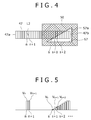
- FIG. 4 illustrates a photo-detecting portion
- FIG. 5 is a graph illustrating amounts of received light detected by a line sensor
- FIGS. 6A , 6 B and 6 C illustrate the automatic focus control unit in the state where an object lens is switched to cause the misalignment of optical axis
- FIG. 6A illustrating the optical axis deviating rightward on the line sensor
- FIG. 6B illustrating the optical axis not deviating on the line sensor
- FIG. 6C illustrating the optical axis deviating leftward on the line sensor
- FIGS. 7A and 7B are graphs illustrating the amount of a received reflected laser beam detected by reference elements
- FIG. 8 illustrates the automatic focus control unit in which a little more than half of an emission laser beam is shielded by a knife-edge mirror
- FIG. 9 is a schematic diagram illustrating a configuration of an automatic focus control unit arranged with a pair of cylindrical lenses
- FIG. 10 is a schematic diagram illustrating a configuration of an automatic focus control unit arranged with a single cylindrical lens
- FIG. 11 illustrates a photo-detecting portion in the automatic focus control unit arranged with the single cylindrical lens
- FIG. 12 is a schematic diagram illustrating a traditional focus control unit
- FIG. 13 is a schematic diagram illustrating the traditional focus control unit with a switched object lens.
- the microscope 1 includes an object lens unit 10 provided with a plurality of object lenses 2 different in magnification from each other; an image pick-up unit 11 adapted to receive reflected light resulting from a laser beam directed to and reflected from a testing sample 3 , and provided with an image pick-up element 4 ; and an illumination unit 12 for illuminating the objective lens 2 with illumination light through the objective lens 2 .
- the object lens unit 10 further includes an automatic focus control unit 13 for detecting the focal point of the object lens 2 relative to the testing sample 3 ; a drive unit 14 for varying the distance between the object lens unit 10 and a stage on which the testing sample 3 is placed depending on the detection results; and a controller 15 for driving the drive unit 14 depending on the detection results of the automatic focus control unit 13 .
- Such a microscope 1 can switchably use the objective lenses 2 different in magnification from each other in association with the testing sample 3 or a check portion by turning the object lens unit 10 .
- the microscope 1 can allow the automatic focus control unit 13 to execute focus detection depending on the objective lens 2 switched.
- the object lens unit 10 includes the plurality of object lenses 2 a , 2 b , etc.; a revolver 20 attached with the object lenses 2 ; a revolver support portion 21 for turnably supporting the revolver 20 ; and a detection section not illustrated for detecting which one of attachment holes formed in the revolver 20 receives the object lens 2 attached thereto.
- the revolver 20 is formed on an outer circumferential surface with a plurality of the attachment holes adapted to receive the object lenses 2 attached thereto. Specifically, the plurality of object lenses 2 a , 2 b , etc. different in magnification from each other are attached to the attachment holes.
- the revolver support portion 21 supports the revolver 20 so that the object lenses 2 may be moved on the optical path of the microscope 1 .
- the revolver support portion 21 incorporates a rotary motor mechanism for turning the revolver 20 .
- the revolver support portion 21 is connected to the illumination unit 12 and attached with the drive unit 14 .
- Such an object lens unit 10 is supported in the state where the optical axis of a single object lens 2 is aligned with the optical path of the microscope 1 by automatically or manually turning the revolver 20 .
- the object lens unit 10 is such that the object lens 2 selected is opposed to the stage so that the testing sample 3 placed on the stage can be checked at a desired magnification.
- the image pick-up unit 11 is disposed opposite the object lens unit 10 and constitutes an observation optical system whose optical path diverges from the illumination unit 12 described below and the automatic focus control unit 13 .
- the image pick-up unit 11 includes a lens barrel section 25 incorporating a collective lens group; and a camera section 26 incorporating an image pick-up element 27 such as a CCD or the like.
- the image pick-up unit 11 is such that the camera section 26 produces a video signal of the testing sample 3 and routes it to a monitor not illustrated.
- the illumination unit 12 emits a desired quantity of light from an illumination light source 30 to the testing sample 3 for illumination so that the image pick-up unit 11 can check it.
- the illumination unit 12 includes a first lens 32 , an aperture diaphragm 33 , a second lens 34 and an illumination mirror 35 which are disposed on the same optical axis in the lens barrel 31 .
- the light emitted from the illumination light source 30 is collected by the first lens 32 and directed to the second lens 34 via the aperture diaphragm 33 .
- the light directed to the second lens 34 is made to have a predetermined spot diameter, reflected by the illumination mirror 35 toward the object lens unit 10 and directed to the testing sample 3 .
- FIG. 2 illustrates an embodiment of the automatic focus control unit 13
- FIG. 3 is a schematic diagram illustrating a configuration of the automatic focus control unit 13 .
- the automatic focus control unit 13 includes an irradiation portion 40 for emitting an emission laser beam L 1 for focus control and a photo-detecting portion 41 for detecting a reflected laser beam L 2 resulting from the emission laser beam L 1 emitted from the irradiation portion 40 to the testing sample 3 and reflected therefrom.
- the irradiation portion 40 includes a first light-emitting element 42 for emitting the emission laser beam L 1 ; a knife-edge mirror 43 for shielding at least a portion of the laser beam L 1 emitted from the first light-emitting element 42 ; a collimator lens 44 for converting the divergence angle of the laser beam L 1 emitted from the first light-emitting element 42 to bring the emission laser beam L 1 into parallel light; and a dichroic mirror 45 adapted to reflect the emission laser beam L 1 that passed through the collimator lens 44 , toward the object lens unit 10 .
- the first light-emitting element 42 uses e.g. a semiconductor laser diode.
- the knife-edge mirror 43 is such that its edge portion is disposed on the optical axis of the laser beam L 1 emitted from the first light-emitting element 42 and of the laser beam L 2 reflected from the testing sample 3 .
- a plane opposed to the first light-emitting element 42 is formed as a shielding plane which prevents the transmission of a laser beam and which shields about 55% of the emission laser beam L 1 .
- a plane on the side opposed with the shielding surface opposed to the first light-emitting element 42 is formed as a mirror surface, which fully reflects the laser beam L 2 reflected from the testing sample 3 toward the photo-detecting portion 41 .
- the dichroic mirror 45 reflects toward the object lens unit 10 the emission laser beam L 1 brought into the parallel light by the collimator lens 44 .
- the dichroic mirror 45 reflects the laser beam L 2 reflected from the testing sample 3 , toward the knife-edge mirror 43 and transmits it toward the image pick-up unit 11 .
- the photo-detecting portion 41 for detecting the laser beam L 2 reflected by the knife-edge mirror 43 includes a line sensor 47 having a plurality of light-receiving elements arranged therein; a slide mechanism 48 for sliding the line sensor 47 in the arrangement direction of the light-receiving elements; a second light-emitting element 49 for directing LED-light to a portion of the light-receiving elements formed in the line sensor 47 ; and a slit member 50 for restricting an area of the line sensor 47 irradiated with the LED-light emitted from the second light-emitting element 49 .
- the line sensor 47 is composed of the plurality of generally rectangular, arranged light-receiving elements and detects an amount of light incident on each of the light-receiving elements. Based on the amount of light received by predetermined light-receiving elements of the line sensor 47 , the controller 15 produces a focus error signal and drives the drive unit 14 for focusing control. In addition, the light amount of the predetermined light-receiving elements to which LED-light is directed via the slit member 50 is recorded in association with the object lens 2 . Every time the object lens 2 is switched, the line sensor 47 is slid to a predetermined position by the slide mechanism 48 based on the predetermined light-receiving elements and the amount of received light recorded in association with the object lens 2 switched.
- such a line sensor 47 is formed on the slider 51 so as to be slidable in the direction of arrow S perpendicular to the optical axis of the reflected laser beam L 2 and in the direction opposite thereto.
- the slider 51 is slidably supported by a housing constituting part of the photo-detecting portion 41 and is constantly biased in the direction of arrow S by a spring 52 abutted against the slide-directional one end thereof.
- the slider 51 is formed with an abutment portion 53 located in the biasing direction of the spring 52 .
- a lever 55 of the slide mechanism 48 is abutted against the abutment portion 53 .
- the slider 51 is slid in the direction of arrow S and in the direction opposite thereto by swinging the lever 55 .
- the slide mechanism 48 for sliding the line sensor 47 includes a piezo actuator 54 and the lever 55 illustrated in e.g. FIG. 2 .
- the piezo actuator 54 receives voltage necessary to allow the controller 15 to slide the line sensor 47 in association with the object lens 2 .
- the lever 55 is turnably supported by the housing of the photo-detecting portion 41 and has one end abutted against the piezo actuator 54 and the other end abutted against the abutment portion 53 of the slider 51 .
- the lever 55 receives the biasing force of the spring 52 via the abutment portion 53 to be constantly turnably biased in the direction of arrow R in FIG. 2 .
- the slide mechanism 48 slides the line sensor 47 in the direction perpendicular to the optical axis of the reflected laser beam L 2 to a reference position where the reflective laser beam L 2 is directed to predetermined light-receiving elements of the line sensor in association with the object lens 2 .
- the photo-detecting portion 41 includes the second light-emitting element 49 for emitting LED-light to the light-receiving elements of the line sensor 47 and the slit member 50 for restricting the area irradiated with the LED-light emitted from the second light-receiving element 49 .
- the second light-emitting element 49 and slit member 50 are opposed to the line sensor 47 .
- the second light-emitting element 49 uses e.g. a light-emitting diode.
- the slit member 50 is formed with an opening portion 57 adapted to direct the LED-light emitted from the second light-emitting element 49 to the plurality of light-receiving elements.
- These light-receiving elements are provided on the other end 47 b on the side opposite to the one end 47 a of the line sensor 47 formed with the light-receiving elements to which the laser beam L 2 reflected from the testing sample 3 is directed.
- the opening portion 57 is formed with an oblique side 57 a adapted to sequentially and gradually increase in the arrangement direction the irradiation area of the light-receiving elements arranged close to the other end 47 b .
- the oblique side 57 a obliquely cuts across at least three of the light-receiving elements arranged close to the other end 47 b . In this way, the light-emitting elements of the line sensor 47 opposed to the second light-emitting element 49 via the opening portion 57 are increased in the area irradiated with the LED-light along the arrangement direction so that the detected amount of light is increased stepwise.
- the photo-detecting portion 41 can determine a position of the line sensor 47 with respect to the slit member 50 based on the predetermined light-receiving elements to which the LED-light is directed from the second light-emitting element 49 via the slit member 50 and on the amount of light directed to the predetermined light-receiving elements.
- the automatic focus control unit 13 allows the emission laser beam L 1 to be focused on the testing sample 3 for each of the object lenses 2 provided in the object lens unit 10 . This sets the reference position where the laser beam L 2 reflected from the testing sample 3 is directed equally in quantity to the predetermined light-receiving elements arranged close to the one end 47 a of the line sensor 47 . At this reference position, the automatic focus control unit 13 registers as reference elements the predetermined light-receiving elements which is arranged close to the other end 47 b of the line sensor 47 and to which the LED-light is directed from the second light-emitting element 49 . In addition, the automatic focus control unit 13 registers as reference voltage the amount of light directed to the predetermined light-receiving elements from the second light-emitting element 49 .
- the automatic focus control unit 13 determines a reference position of the line sensor 47 associated with the object lens 2 thus switched on the basis of the reference elements and reference signal registered.
- the line sensor 47 is automatically shifted to the reference position by being slid by the slide mechanism 48 until the reference element provides the voltage level of the reference signal.
- the automatic focus control unit 13 allows the emission laser beam L 1 to be focused on the testing sample 3 via one object lens 2 and determines as a reference position a position where two light-receiving elements n, n+1 arranged close to the one end 47 a of the line sensor 47 equally receive the laser beam L 2 reflected from the testing sample 3 .
- a reference position is determined for each of the object lenses 2 a , 2 b , etc. provided in the object lens unit 10 ( FIG. 4 ).
- the object lenses 2 a , 2 b , etc. are each focused on the testing sample 3 , the two light-receiving elements n, n+1 equally receive the reflected laser beam L 2 directed thereto so that the voltage levels Vn, Vn+1 are equal to each other.
- the automatic focus control unit 13 provides a plurality of light-emitting elements s, s+1, s+2, etc. arranged on the other end 47 b of the line sensor 47 at each of the associated reference positions so as to receive the LED-light of the second light-emitting element 49 directed thereto via the opening portion 57 of the slit member 50 and the voltage levels Vs, Vs+1, Vs+2, etc. corresponding respectively to the amounts of light received by the light-receiving elements s, s+1, s+2, etc.
- the light-emitting elements s, s+1, s+2, etc are increased stepwise to provide light-receiving amounts Vs, Vs+1, Vs+2, etc., respectively.
- the automatic focus control unit 13 Upon selecting the object lens 2 a of the object lens unit 10 , the automatic focus control unit 13 registers, as reference elements associated with the object lens 2 a , the element numbers of the two light-receiving elements n, n+1 equally receiving the reflected laser beam L 2 directed thereto, and the element numbers of the light-receiving elements s, s+1, s+2, etc. obtaining the stepwise signals. In addition, the automatic focus control unit 13 resisters, as the reference signal associated with the object lens 2 a , the stepwise voltage levels Vs, Vs+1, Vs+2, etc. detected in the light-receiving elements s, s+1, s+2, etc., respectively.
- the automatic focus control unit 13 similarly registers reference elements and reference signals for the object lens 2 b and the other object lenses.
- the reference elements and the voltage levels of the reference signals may be different from each other or the same for every object lens 2 .
- the reflected laser beam L 2 is directed to a position deviating from the light-receiving elements n, n+1 which are the reference elements associated with the object lens 2 b switched.
- the line sensor 47 is slid in the arrangement direction of the light-receiving elements by the slide mechanism 48 so that the two reference elements n, n+1 may equally receive the reflected laser beam L 2 . In this way, the automatic position adjustment of the line sensor is performed.
- the element numbers of the light-receiving elements n, n+1 to which the laser beam L 2 reflected from the testing sample 3 is equally directed and of the plurality of light-receiving elements s, s+1, s+2, etc. to which the LED-light is directed from the second light-emitting element 49 are registered as the reference elements associated with the object lens 2 b .
- the signals Vs, Vs+1, Vs+2, etc. detected respectively by the light-receiving elements s, s+1, s+2, etc. are registered as the reference signals associated with the object lens 2 b.
- the automatic focus control unit 13 allows the slide mechanism 48 to slide the line sensor 47 until the reference elements s, s+1, s+2, etc. previously registered in association with the object lens 2 b measure the reference signals Vs, Vs+1, Vs+2, etc., respectively. In this way, the line sensor 47 is constantly maintained at the reference position associated with the object lens 2 b.
- the automatic focus control unit 13 can automatically slide the line sensor 47 to the reference position where such misalignment of optical axis or color aberration has previously been corrected. This can perform focusing with speed and accuracy.
- the microscope 1 allows the drive unit 14 to shift the stage on which the testing sample 3 is placed or the object lens unit 10 in the focusing direction, i.e., in the optical-axial direction of the object lens 2 for automatic focusing while the automatic focus control unit 13 maintains the line sensor 47 at the reference position associated with the selected object lens 2 so that the laser beam L 2 reflected from the testing sample 3 may be directed to the reference elements n, n+1 equally in quantity.
- the automatic focusing described above is performed by the controller 15 which monitors the amounts of the reflected laser beams L 2 received by the reference elements n, n+1, produces focus servo signals and feeds them back to the drive unit 14 .
- the line sensor 47 detects the amount of light or the level of light directed to each of the reference elements n, n+1 as shown in FIG. 7A .
- the controller 15 gets a difference by subtracting the signal of the reference element n+1 from the signal of the reference element n as shown in FIG. 7B . Based on the so-called focus error signal obtained as an S-curve as shown in the figure, the controller 15 drives the object lens 2 .
- the automatic focus control unit 13 allows the drive unit 14 to drive the object lens unit 10 in the optical-axial direction of the object lens 2 so that the distance between the object lens 2 and the testing sample 3 may be equal to the focal length and the amounts of light directed to the light-receiving elements n, n+1 may become equal to each other.
- the controller 15 controls the drive unit 14 so that the object lens unit 10 is stopped at a point (a zero-cross point), indicated with symbol JF in FIG. 7B , where the subtracted value between the amounts of light received by the light-receiving elements n, n+1 indicates a value equal to zero.
- the object lens unit 10 is shifted downward aiming the just focus point JF.
- the object lens unit 10 is shifted upward aiming the just focus point JF.
- the microscope 1 can perform fast focusing on the testing sample 3 without largely deviating from the focal point of the object lens 2 .
- the microscope 1 As described above, while the illumination unit 12 shines the illumination light on the testing sample 3 , the microscope 1 having been subjected to the focusing by the automatic focus control unit 13 uses such light and allows the imaging unit 5 to pick up an image of the testing sample 3 .
- the reference position is set where the reflective laser beam L 2 is equally directed to the plurality of light-receiving elements provided close to the one end 47 a of the line sensor 47 .
- the automatic focus control unit 13 registers the plurality of light-receiving elements n, n+1 and the plurality of light-receiving elements s, s+1, s+2, etc. in an embedded memory as the reference elements associated with the selected objective lens.
- the plurality of light-receiving elements n, n+1 are provided close to the one end 47 a of the line sensor 47 with respect to the reference position to receive the same amount of the reflective laser beam L 2 .
- the plurality of light-receiving elements s, s+1, s+2, etc. are provided close to the other end 47 b of the line sensor 47 and are such that the irradiation area of the LED-light emitted from the second light-emitting element 49 is gradually increased through the slit member 50 .
- the automatic focus control unit 13 detects the amounts of light received by the reference elements s, s+1, s+2, etc. and registers the voltage levels associated therewith as the reference signals in the embedded memory.
- the position where the reflected laser beam L 2 is directed to the light-receiving elements n, n+1 equally in quantity is set as the reference position of the line sensor 47 .
- the light-receiving elements n, n+1 associated with the reference position and the light-receiving elements s, s+1, s+2, etc. adapted to receive the LED-light of the second light-emitting element 49 are registered as the reference elements.
- the amounts of light received by the reference elements s, s+1, s+2, etc. are registered as the reference signals in the embedded memory.
- the automatic focus control unit 13 sets the reference elements and reference signals in accordance with the reference position of the line sensor 47 for each of the objective lenses 2 a , 2 b , etc. provided in the objective lens unit 10 , and thereafter the testing sample 3 is checked.
- the microscope 1 is used by switching between the object lenses 2 . Specifically, if the testing sample 3 has a large size, a low-power object lens 2 is selected in detecting an alignment mark, whereas a high-power object lens 2 is selected in observing a particular position of the testing sample 3 .
- the automatic focus control unit 13 slides the line sensor 47 to the reference position based on the reference elements and reference signals previously set in association with the object lens 2 switched.
- the automatic focus control unit 13 can perform automatic focusing fast and reliably even if the misalignment of the optical axis or color aberration occurs due to the switching of the object lens 2 .
- the line sensor 47 is slid to the reference position by the slide mechanism 48 which slides the slider 51 in the direction of arrow S or in the direction opposite thereto so that the reference elements s, s+1, s+2, etc. may have the corresponding voltage levels of the reference signals.
- the line sensor 47 is slid in the arrangement direction of the light-receiving elements perpendicular to the optical-axial direction of the reflected laser beam L 2 so that the reflected laser beam L 2 is directed to both the reference elements n, n+1.
- the drive unit 14 drives the object lens unit 10 so that the same amount of the reflected laser beam L 2 is directed to the reference elements n, n+1.
- the amounts of the light received by the reference elements n, n+1 are detected by the automatic focus control unit 13 , and based on the detected values the controller 15 produces a focus error signal.
- the microscope 1 allows the drive unit 14 to shift the object lens unit 10 in the focusing direction, i.e., in the optical-axial direction.
- the object lens unit 10 is shifted until the amounts of light received by the reference elements n, n+1 become equal to each other, whereby the microscope 1 completes the focusing on the testing sample 3 .
- the microscope 1 allows the line sensor 47 to be slid to the reference position and the object lens unit 10 to be moved upward or downward until the light received by the reference elements n, n+1 becomes equal to each other.
- the automatic focus control unit 13 maintains the focusing, whereby measurement or check after or during the movement can be performed fast.
- the automatic focus control unit 13 monitors the voltages of the reference signals of the reference elements s, s+1, s+2, etc. previously registered in association with the selected object lens 2 , slides the line sensor 47 to cancel the difference relative to such a reference signal, thereby maintaining the reference position.
- the automatic focus control unit 13 allows the drive unit 14 to shift the object lens unit 10 in the optical-axial direction of the object lens 2 so that the reference elements n, n+1 may equally receive the laser beam L 2 reflected from the testing sample 3 being traced.
- the automatic focus control unit 13 can automatically perform the focusing even during the tracing operation.
- the opening portion 57 and oblique side 57 a of the slit member 50 are formed so that the LED-light of the second light-emitting element 49 may be directed to five or more of the light-receiving elements arranged close to the other end 47 b of the line sensor 47 .
- Three light-receiving elements resulting from excluding the light-receiving elements on both sides, e.g., the three middle light-receiving elements, are selected as the light-receiving elements s, s+1, s+2 adapted to detect the reference signals.
- the signals Vs, Vs+1, Vs+2 detected respectively by the three light-receiving elements thus selected are registered as reference signals. In this way, even if light directed to edge portions of the opening portion 57 of the slit member 50 varies in quantity, the reference signal can stably be detected so that the line sensor 47 can reliably be shifted to the reference position.
- the slit member 50 is such that the opening portion 57 is opened more largely than the light-receiving elements close to the other end 47 b of the line sensor 47 .
- the light-receiving elements close to the other end 47 b of the line sensor 47 are opposed to the second light-emitting element 49 over the whole surface thereof so as to receive the LED-light through over the whole surface thereof.
- a plurality of the light-receiving elements subjected to the whole surface irradiation are provided adjacently to the light-receiving elements which are gradually increased in quantity of light directed thereto.
- the LED-light directed to the second light-emitting element 49 provides predetermined power by measuring the quantity of light directed to the light-emitting elements subjected to the whole surface irradiation.
- the slit member 50 described above is such that the oblique side 57 a of the opening portion 57 is set to have an angle of 35° in the case of using the line sensor 47 as below.
- the light-receiving elements of the line sensor 47 are each formed to have a longitudinal length of 200 ⁇ m and a width of 54.5 ⁇ m and have a pitch of 9 ⁇ m.
- the light-receiving elements have element numbers 1 through 128 from the one end 47 a to the other end 47 b.
- the knife edge mirror 43 disposed in the automatic focus control unit 13 is adapted to shield a little more than half (about 55%) of the laser beam L 1 emitted from the first light-emission element 42 and direct about 45% of the emitted laser beam L 1 toward the collimator lens 44 .
- the object lens 2 may be switched to cause the misalignment of optical axis.
- the laser beam L 2 reflected from the testing sample 3 may enter the first light-emitting element 42 using a semiconductor laser diode in some cases. If the reflected laser beam L 2 enters the first light-emitting element 42 , the emission laser beam L 1 is made to resonate, which makes laser power unstable, with the result that automatic focusing may probably be adversely affected.
- the automatic focus control unit 13 allows the knife-edge mirror 43 , an optical path splitting member, to shield a little more than half (about 55%) of light flux and direct, not shielded, about 45% of the emission laser beam L 1 into the collimator lens 44 . In this way, the automatic focus control unit 13 can prevent the laser beam L 2 reflected from the testing sample 3 from entering the first light-emitting element 42 even if the misalignment of optical axis occurs. Thus, the automatic focusing can be performed precisely and reliably.
- the automatic focus control unit 13 may include a pair of cylindrical lenses 60 , 61 as optical devices having refractive forces different from each other in the perpendicular direction and located on the optical path of the laser beam L 1 emitted from the first light-emitting element 42 .
- the automatic focus control unit 13 can shape the laser beam L 1 directed to the testing sample 3 into a general ellipse to minimize the influence of uneven edges of the testing sample 3 .
- the emission laser beam L 1 is directed to the testing sample 3 , e.g. to a semiconductor wafer formed with uneven edges on the front surface, the emission laser beam L 1 is scattered by the uneven edges resulting from pattern formation to make the amount of the reflected laser beam L 2 insufficient.
- the amount of the reflected LED-light L 2 received by the line sensor 47 is insufficient, which may probably adversely affect the accuracy of focusing. Consequently, the automatic focus control unit 13 produces the elliptical laser beam by use of the cylindrical lenses 60 , 61 and directs it to the testing sample 3 .
- the influence of the scattering by the uneven edges can be minimized.
- the cylindrical lens 60 is disposed between the first light-emitting element 42 and the knife-edge mirror 43 and the cylindrical lens 61 is disposed between the mirror surface of the knife-edge mirror 43 and the line sensor 47 .
- the cylindrical lens 60 allows the laser beam L 1 emitted from the first light-emitting element 42 to cause astigmatism, thereby shaping it into an elliptical shape from a circular spot.
- the emission laser beam L 1 deformed like an elongate hole is shielded by the knife-edge mirror 43 by a little more than half (about 55%) and the remaining one is directed to the collimator lens 44 . Thereafter, as described earlier, the emission laser beam L 1 is reflected by the dichroic mirror 45 toward the object lens unit 10 and directed to the testing sample 3 . In this case, the emission laser beam L 1 directed to the testing sample 3 is shaped into an ellipse by the cylindrical lens 60 .
- the laser beam L 2 reflected from the testing sample 3 is passed through the dichroic mirror 45 and directed to the imaging unit 11 constituting part of the observation optical system and also it is reflected from the mirror surface of the dichroic mirror 45 and of the knife-edge mirror 43 and directed to the cylindrical lens 61 .
- the reflected laser beam L 2 is again directed to the cylindrical lens to be deformed into the circular spot from the ellipse and is received by the line sensor 47 .
- the automatic focus control unit 13 detects the amounts of reflected laser beam L 2 directed to the reference elements n, n+1 of the line sensor 47 .
- the controller 15 controls the drive unit 14 so that the amounts of the reflected laser beam L 2 directed to the reference elements n, n+1 may be made equal to each other. That is to say, the drive unit 14 shifts the object lens unit 10 or the stage on which the testing sample 3 is placed, in the optical-axial direction for automatic focusing.
- the automatic focus control unit 13 may be such that the cylindrical lens 62 is disposed singularly or it is disposed between the knife-edge mirror 43 and the collimator lens 44 as shown in FIG. 10 .
- the reflected laser beam L 2 directed to the reference elements n, n+1 of the line sensor 47 is focused into an eclipse with a longitudinal direction perpendicular to the arrangement direction of the light-receiving elements as shown in FIG. 11 .
- the amount of the reflected laser beam L 2 is enough unless it is directed to the outside of the light-receiving elements of the line sensor 47 .
- the controller 15 controls the drive unit 14 so that the amounts of the reflected laser beam L 2 directed to the reference elements n, n+1 may be equal to each other. That is to say, the drive unit 14 shifts the object lens unit 10 or the stage on which the testing sample is placed, in the optical-axial direction for automatic focusing.
- the application of the automatic focus control unit and method according to the embodiments of the present invention is not limited to the optical microscope.
- they can be applied to optical electronic equipment such as depth meters and automatic focus control units of laser processing machines.
- the automatic focus control unit according to the embodiments of the present invention can be used by being built in electronic devices such as normal microscopes used heretofore.
- the slide mechanism 48 for sliding the line sensor 47 is not limited to the configuration using the piezo actuator but can be applied to any mechanism for sliding the line sensor 47 along the arrangement direction of the light-receiving elements.
Landscapes
- Physics & Mathematics (AREA)
- Chemical & Material Sciences (AREA)
- Analytical Chemistry (AREA)
- General Physics & Mathematics (AREA)
- Optics & Photonics (AREA)
- Automatic Focus Adjustment (AREA)
- Microscoopes, Condenser (AREA)
Abstract
Description
Claims (10)
Applications Claiming Priority (2)
| Application Number | Priority Date | Filing Date | Title |
|---|---|---|---|
| JP2008103984A JP4553030B2 (en) | 2008-04-11 | 2008-04-11 | Automatic focus control unit, electronic equipment, automatic focus control method |
| JP2008-103984 | 2008-04-11 |
Publications (2)
| Publication Number | Publication Date |
|---|---|
| US20090256058A1 US20090256058A1 (en) | 2009-10-15 |
| US8071929B2 true US8071929B2 (en) | 2011-12-06 |
Family
ID=41163196
Family Applications (1)
| Application Number | Title | Priority Date | Filing Date |
|---|---|---|---|
| US12/406,462 Active 2030-06-18 US8071929B2 (en) | 2008-04-11 | 2009-03-18 | Automatic focus control unit, electronic device and automatic focus control method |
Country Status (5)
| Country | Link |
|---|---|
| US (1) | US8071929B2 (en) |
| JP (1) | JP4553030B2 (en) |
| KR (1) | KR101484323B1 (en) |
| CN (1) | CN101556373B (en) |
| TW (1) | TWI398717B (en) |
Cited By (3)
| Publication number | Priority date | Publication date | Assignee | Title |
|---|---|---|---|---|
| US8894206B2 (en) | 2011-12-29 | 2014-11-25 | Industrial Technology Research Institute | Auto-focusing diagnostic equipment |
| US20180210162A1 (en) * | 2017-01-25 | 2018-07-26 | Specim, Spectral Imaging Oy Ltd | Imaging apparatus and operating method |
| US10317663B2 (en) | 2015-02-27 | 2019-06-11 | General Electric Company | Determination of deflection of a microscope slide |
Families Citing this family (13)
| Publication number | Priority date | Publication date | Assignee | Title |
|---|---|---|---|---|
| TWI428654B (en) * | 2010-11-23 | 2014-03-01 | Ind Tech Res Inst | Auto-focusing module and method applicable thereto |
| JP5293782B2 (en) * | 2011-07-27 | 2013-09-18 | 三星ダイヤモンド工業株式会社 | In-focus position adjusting method, in-focus position adjusting apparatus, and laser processing apparatus |
| US8687180B2 (en) * | 2012-06-07 | 2014-04-01 | Molecular Devices, Llc | System, method, and device for determining a focal position of an objective in a microscopy imaging system |
| TWI574072B (en) * | 2015-04-17 | 2017-03-11 | 國立中正大學 | Automatic focusing system and focusing method thereof |
| CN107315240B (en) * | 2017-07-28 | 2024-04-26 | 佛山市好客电子科技有限公司 | Portable microscopic device |
| CN108761421A (en) * | 2018-03-20 | 2018-11-06 | 深圳市速腾聚创科技有限公司 | A kind of solid-state laser radar |
| DE102019113540A1 (en) * | 2019-05-21 | 2020-11-26 | Carl Zeiss Microscopy Gmbh | Light microscope with automatic focusing |
| DE102020213714A1 (en) * | 2020-11-01 | 2022-05-05 | Carl Zeiss Microscopy Gmbh | Microscope and method for light field microscopy with light sheet excitation and for confocal microscopy |
| CN112859317A (en) * | 2021-01-20 | 2021-05-28 | 宁波舜宇仪器有限公司 | Automatic focusing microscopic imaging system |
| CN114086790B (en) * | 2021-11-19 | 2022-05-17 | 六安金銮建筑设备有限公司 | Intelligent building wall crack repairing equipment based on Internet of things |
| KR20240155884A (en) * | 2022-02-11 | 2024-10-29 | 마이크로-엡실론 옵트로닉 게엠바하 | System and method for measuring confocal-chromatic distance |
| CN115984531A (en) * | 2022-12-28 | 2023-04-18 | 芜湖圣美孚科技有限公司 | Light processing system based on machine vision |
| WO2025072986A1 (en) * | 2023-10-04 | 2025-04-10 | Akrima Gmbh | Attachment device for a microscope |
Citations (7)
| Publication number | Priority date | Publication date | Assignee | Title |
|---|---|---|---|---|
| JPH10161195A (en) | 1996-12-02 | 1998-06-19 | Sony Corp | Autofocus method and autofocus device |
| JPH11249027A (en) | 1998-03-02 | 1999-09-17 | Olympus Optical Co Ltd | Automatic focusing microscope |
| US6567126B1 (en) * | 1998-07-08 | 2003-05-20 | Hewlett-Packard Company | Planar focus correction |
| US20060249651A1 (en) * | 2004-12-24 | 2006-11-09 | Olympus Corporation | Image inspection system for correcting focal position in autofocusing |
| US7301133B2 (en) * | 2005-01-21 | 2007-11-27 | Photon Dynamics, Inc. | Tracking auto focus system |
| US7345814B2 (en) * | 2003-09-29 | 2008-03-18 | Olympus Corporation | Microscope system and microscope focus maintaining device for the same |
| US20080111911A1 (en) * | 2006-11-15 | 2008-05-15 | Olympus Corporation | Autofocus device, method of controlling the same, and microscope system using the same |
Family Cites Families (7)
| Publication number | Priority date | Publication date | Assignee | Title |
|---|---|---|---|---|
| JPH0690033B2 (en) * | 1989-03-27 | 1994-11-14 | 株式会社ミツトヨ | Displacement detection device |
| JP2846041B2 (en) * | 1990-03-08 | 1999-01-13 | キヤノン株式会社 | Image projection device |
| JPH04121831A (en) * | 1990-09-11 | 1992-04-22 | Nec Gumma Ltd | Optical pickup |
| JP3390106B2 (en) | 1995-06-06 | 2003-03-24 | 株式会社日立国際電気 | Optical microscope with automatic focusing device |
| JP4099690B2 (en) | 2000-07-25 | 2008-06-11 | 村田機械株式会社 | Document reader with automatic focus adjustment function |
| JP2003075714A (en) * | 2001-09-03 | 2003-03-12 | Nikon Corp | Focus detection device and microscope with focus detection function |
| US7315493B2 (en) * | 2004-01-30 | 2008-01-01 | Hewlett-Packard Development Company, L.P. | Apparatus and method for calibrating a laser imagible apparatus |
-
2008
- 2008-04-11 JP JP2008103984A patent/JP4553030B2/en active Active
-
2009
- 2009-03-04 TW TW098107013A patent/TWI398717B/en active
- 2009-03-09 KR KR20090019632A patent/KR101484323B1/en active Active
- 2009-03-18 US US12/406,462 patent/US8071929B2/en active Active
- 2009-04-10 CN CN2009101344265A patent/CN101556373B/en active Active
Patent Citations (7)
| Publication number | Priority date | Publication date | Assignee | Title |
|---|---|---|---|---|
| JPH10161195A (en) | 1996-12-02 | 1998-06-19 | Sony Corp | Autofocus method and autofocus device |
| JPH11249027A (en) | 1998-03-02 | 1999-09-17 | Olympus Optical Co Ltd | Automatic focusing microscope |
| US6567126B1 (en) * | 1998-07-08 | 2003-05-20 | Hewlett-Packard Company | Planar focus correction |
| US7345814B2 (en) * | 2003-09-29 | 2008-03-18 | Olympus Corporation | Microscope system and microscope focus maintaining device for the same |
| US20060249651A1 (en) * | 2004-12-24 | 2006-11-09 | Olympus Corporation | Image inspection system for correcting focal position in autofocusing |
| US7301133B2 (en) * | 2005-01-21 | 2007-11-27 | Photon Dynamics, Inc. | Tracking auto focus system |
| US20080111911A1 (en) * | 2006-11-15 | 2008-05-15 | Olympus Corporation | Autofocus device, method of controlling the same, and microscope system using the same |
Cited By (3)
| Publication number | Priority date | Publication date | Assignee | Title |
|---|---|---|---|---|
| US8894206B2 (en) | 2011-12-29 | 2014-11-25 | Industrial Technology Research Institute | Auto-focusing diagnostic equipment |
| US10317663B2 (en) | 2015-02-27 | 2019-06-11 | General Electric Company | Determination of deflection of a microscope slide |
| US20180210162A1 (en) * | 2017-01-25 | 2018-07-26 | Specim, Spectral Imaging Oy Ltd | Imaging apparatus and operating method |
Also Published As
| Publication number | Publication date |
|---|---|
| KR101484323B1 (en) | 2015-01-28 |
| KR20090108525A (en) | 2009-10-15 |
| JP2009258177A (en) | 2009-11-05 |
| TWI398717B (en) | 2013-06-11 |
| CN101556373A (en) | 2009-10-14 |
| CN101556373B (en) | 2011-06-08 |
| JP4553030B2 (en) | 2010-09-29 |
| TW200944921A (en) | 2009-11-01 |
| US20090256058A1 (en) | 2009-10-15 |
Similar Documents
| Publication | Publication Date | Title |
|---|---|---|
| US8071929B2 (en) | Automatic focus control unit, electronic device and automatic focus control method | |
| US11592653B2 (en) | Automated focusing system for tracking specimen surface with a configurable focus offset | |
| US7706597B2 (en) | Defect inspection apparatus and defect inspection method | |
| JP5207213B2 (en) | Autofocus device | |
| US8873138B2 (en) | Auto focusing devices for optical microscopes | |
| US7692856B2 (en) | Focus error detecting optical system for a microscope | |
| CN110073203B (en) | Method and apparatus for inspecting defects on transparent substrates | |
| US9025243B2 (en) | Microscope apparatus | |
| JP7168798B2 (en) | Method and Apparatus for Confirming Confocality of Scanning and Descanning Microscope Assemblies | |
| KR20180025262A (en) | Optical apparatus, machining apparatus, and article manufacturing method, and computer readable storage medium | |
| JP2003232989A (en) | Automatic focusing module for system of microscopic base, microscopic system having automatic focusing module and automatic focusing method for system of microscopic base | |
| CN101019057A (en) | Lens system adjusting device and lens system adjusting method using the same | |
| JPH10161195A (en) | Autofocus method and autofocus device | |
| US6549290B2 (en) | Method and apparatus for aligning target object | |
| JP2005241607A (en) | Apparatus for measuring angle | |
| JP2008145160A (en) | Optical displacement sensor and its adjusting method | |
| JP2000162506A (en) | Confocal microscope | |
| EP2333501A1 (en) | Apparatus and method for automatic optical realignment | |
| KR20180134180A (en) | Laser processing system and calibration for the same | |
| US20100001171A1 (en) | Microscope equipped with automatic focusing mechanism and adjustment method therefor | |
| JP5400499B2 (en) | Focus detection device | |
| JPH09230250A (en) | Optical microscope automatic focusing device | |
| JP2000164680A (en) | Position adjusting device for wafer | |
| US7561338B2 (en) | Microscope objective system | |
| US20110205553A1 (en) | Method for focusing an object plane and optical assembly |
Legal Events
| Date | Code | Title | Description |
|---|---|---|---|
| AS | Assignment |
Owner name: SONY CORPORATION, JAPAN Free format text: ASSIGNMENT OF ASSIGNORS INTEREST;ASSIGNORS:SATO, HIDEKI;HOSHI, MITSUO;KIKUCHI, KIYOYUKI;AND OTHERS;REEL/FRAME:022414/0179;SIGNING DATES FROM 20090227 TO 20090304 Owner name: SONY CORPORATION, JAPAN Free format text: ASSIGNMENT OF ASSIGNORS INTEREST;ASSIGNORS:SATO, HIDEKI;HOSHI, MITSUO;KIKUCHI, KIYOYUKI;AND OTHERS;SIGNING DATES FROM 20090227 TO 20090304;REEL/FRAME:022414/0179 |
|
| FEPP | Fee payment procedure |
Free format text: PAYOR NUMBER ASSIGNED (ORIGINAL EVENT CODE: ASPN); ENTITY STATUS OF PATENT OWNER: LARGE ENTITY |
|
| STCF | Information on status: patent grant |
Free format text: PATENTED CASE |
|
| CC | Certificate of correction | ||
| AS | Assignment |
Owner name: DEXERIALS CORPORATION, JAPAN Free format text: ASSIGNMENT OF ASSIGNORS INTEREST;ASSIGNOR:SONY CORPORATION;REEL/FRAME:029680/0585 Effective date: 20121221 |
|
| FPAY | Fee payment |
Year of fee payment: 4 |
|
| MAFP | Maintenance fee payment |
Free format text: PAYMENT OF MAINTENANCE FEE, 8TH YEAR, LARGE ENTITY (ORIGINAL EVENT CODE: M1552); ENTITY STATUS OF PATENT OWNER: LARGE ENTITY Year of fee payment: 8 |
|
| MAFP | Maintenance fee payment |
Free format text: PAYMENT OF MAINTENANCE FEE, 12TH YEAR, LARGE ENTITY (ORIGINAL EVENT CODE: M1553); ENTITY STATUS OF PATENT OWNER: LARGE ENTITY Year of fee payment: 12 |