JP5400499B2 - Focus detection device - Google Patents
Focus detection device Download PDFInfo
- Publication number
- JP5400499B2 JP5400499B2 JP2009154025A JP2009154025A JP5400499B2 JP 5400499 B2 JP5400499 B2 JP 5400499B2 JP 2009154025 A JP2009154025 A JP 2009154025A JP 2009154025 A JP2009154025 A JP 2009154025A JP 5400499 B2 JP5400499 B2 JP 5400499B2
- Authority
- JP
- Japan
- Prior art keywords
- light
- focus detection
- objective lens
- light beam
- pupil
- Prior art date
- Legal status (The legal status is an assumption and is not a legal conclusion. Google has not performed a legal analysis and makes no representation as to the accuracy of the status listed.)
- Expired - Fee Related
Links
Images


Landscapes
- Microscoopes, Condenser (AREA)
- Automatic Focus Adjustment (AREA)
Description
本発明は、焦点検出装置に関し、特に顕微観察装置において、マイクロプレートやスライドガラスなどの透明基板の所望の表面に焦点合わせを自動的に行うための焦点検出装置に関するものである。 The present invention relates to a focus detection apparatus, and more particularly to a focus detection apparatus for automatically performing focusing on a desired surface of a transparent substrate such as a microplate or a slide glass in a microscopic observation apparatus.
バイオテクノロジーの分野においては、様々な条件下での種々の生細胞の反応を明らかにするため、多数の細胞を対象とした統計解析結果を用いることが頻繁に行われている。このような目的のため、従来、フローサイトメーターと呼ばれる装置が使用されてきたが、近年、顕微観察によって多数の細胞の画像を取得し、取得した画像を解析することにより統計解析結果を得るという手法が用いられるようになってきている。 In the field of biotechnology, statistical analysis results for a large number of cells are frequently used in order to clarify the reactions of various living cells under various conditions. For this purpose, an apparatus called a flow cytometer has been used in the past, but in recent years, images of a large number of cells are acquired by microscopic observation, and statistical analysis results are obtained by analyzing the acquired images. Techniques are beginning to be used.
ところで、このように様々な条件下での生細胞の反応を試験するためには、培養液組成や温湿度などの培養環境条件を制御した多数の容器の中で培養された非常に多くの生細胞を解析対象とする必要があるので、一般にマイクロプレートなどの容器を使用して試験を実施することが行われている。 By the way, in order to test the reaction of living cells under various conditions as described above, a very large number of living cells cultured in a large number of containers in which the culture environment conditions such as the culture solution composition and temperature and humidity are controlled. Since cells need to be analyzed, it is generally carried out using a container such as a microplate.
このため、細胞画像を取得する顕微観察装置としては、マイクロプレートなどの容器の下方より観察する倒立顕微鏡型の光学配置を採用し、さらに視野位置変更、焦点合わせ、撮像などの画像取得にかかわる一連の動作を自動化したものが望まれる。そして、このように顕微観察装置を自動化する場合には、特に焦点合わせの自動化方式が重要である。 For this reason, as a microscopic observation apparatus for acquiring cell images, an inverted microscope type optical arrangement for observing from below a container such as a microplate is adopted, and further, a series of image acquisition such as field position change, focusing, imaging, etc. What automates the operation of is desired. When automating the microscopic observation apparatus in this way, an automatic focusing method is particularly important.
一般的に、焦点合わせの自動化方式には、大別して対象物(被写体)に赤外線などの焦点検出用照明光を照射し、その反射光の光量などを検出することにより焦点を検出するアクティブ方式と、レンズで捉えた画像を利用して焦点を検出するパッシブ方式の2つの方式が存在する。 In general, the automatic focusing method is roughly divided into an active method in which a target (subject) is irradiated with focus detection illumination light such as infrared rays and the amount of reflected light is detected to detect the focus. There are two passive methods for detecting a focus using an image captured by a lens.
しかるに、様々な条件下での種々の生細胞の反応を明らかにすることを目的として細胞画像を取得する顕微観察装置においては、非常に多くの画像を取得する必要があるため、迅速な動作速度を有するアクティブ方式の焦点合わせ方式が採用されることが多い。このようなアクティブ方式の焦点検出装置においては、高い焦点合わせ精度を実現するために焦点検出用照明光束径を対物レンズの瞳径に一致させるのが一般的であり、このようなアクティブ方式を採用した焦点検出装置として、例えば特許文献1に記載のものがある。
However, in order to clarify the reaction of various living cells under various conditions, a microscopic observation apparatus that acquires cell images needs to acquire a very large number of images, so that the rapid operation speed is high. In many cases, an active focusing method having the above is adopted. In such an active focus detection device, in order to achieve high focusing accuracy, it is common to match the illumination beam diameter for focus detection with the pupil diameter of the objective lens, and such an active method is adopted. An example of such a focus detection apparatus is described in
アクティブ方式の焦点検出装置において高い精度で焦点合わせを行うためには、対物レンズの瞳径に焦点検出用照明光束径を一致させることが必要であるが、一方で、対物レンズの瞳径は対物レンズごとに様々であるため、焦点検出用照明光束径を瞳径の大きな低倍率の対物レンズに合わせて最適化すると、瞳径の小さな高倍率の対物レンズに切り換えた場合に焦点検出用照明光束が対物レンズの瞳によってケラレるため、光量不足となって焦点検出を行うことが困難になりやすい。 In order to perform focusing with high accuracy in an active focus detection apparatus, it is necessary to make the illumination beam diameter for focus detection coincide with the pupil diameter of the objective lens. Since it varies from lens to lens, when the focus detection illumination beam diameter is optimized for a low-magnification objective lens with a large pupil diameter, the focus detection illumination beam is switched to a high-magnification objective lens with a small pupil diameter. However, since the vignetting is caused by the pupil of the objective lens, the amount of light is insufficient and it is difficult to perform focus detection.
一方、焦点検出用照明光束の径を瞳径の小さな高倍率の対物レンズに合わせて最適化すると、瞳径の大きな対物レンズに切り換えた場合に実質上、焦点検出装置の被写界深度が深くなって焦点検出の精度が悪化する。したがって、対物レンズごとに焦点検出用照明光の光束径を最適化する必要がある。 On the other hand, when the diameter of the focus detection illumination beam is optimized for a high-magnification objective lens with a small pupil diameter, the depth of field of the focus detection device is substantially increased when switching to an objective lens with a large pupil diameter. As a result, the accuracy of focus detection deteriorates. Therefore, it is necessary to optimize the beam diameter of the focus detection illumination light for each objective lens.
しかるに、特許文献1には、焦点検出用照明光としてレーザを採用し、レーザ光源と対物レンズとの間に、NDフィルタと径の異なる開口絞りを組み合わせた絞りフィルタ組み立て体を備え、レーザ光源のパワーを一定にしたままで、NDフィルタを介してレーザ光量を調節するとともに、開口絞りを選択してレーザ光束径を対物レンズの瞳の径に合わせるようにした構成が開示されている。
However, in
さらに、アクティブ方式を採用した焦点検出装置を用いてマイクロプレートの底面のような透明基板の一方の面に焦点を合わせる場合には、他方の面からの反射光も光検出器で検出されてノイズとなって焦点の検出に悪影響を及ぼすという問題がある。 Furthermore, when focusing on one surface of a transparent substrate such as the bottom surface of a microplate using a focus detection device that employs an active method, reflected light from the other surface is also detected by a photodetector to cause noise. There is a problem that the focus detection is adversely affected.
このため本件出願人は先に、お互いに対向した状態で配置された傾斜面を有し、且つ、該傾斜面の間隔を調節可能な2つの光学部材からなる光束入射位置調節手段により、該2つの光学部材の傾斜面の間隔を調節することで、対物レンズの瞳位置における焦点検出用光束の入射位置を対物レンズの瞳径に応じた瞳内の所定位置に調節して対物レンズに入射させることによって、焦点検出用光束の径を対物レンズの瞳径に合わせて最適化でき、しかも、瞳径の大きな対物レンズに切り換えた場合でも、透明基板における焦点合わせの対象となっていない側の表面からの反射光による悪影響を排除しながら、透明基板における焦点合わせの対象となっている側の表面からの反射光量を高い検出感度で検出し、この焦点合わせの対象となっている側の表面に焦点合わせを行うことが可能な焦点検出装置を開発し特許出願(特願2008−320011号)した。 For this reason, the applicant of the present invention first uses the light beam incident position adjusting means comprising two optical members having inclined surfaces arranged opposite to each other and capable of adjusting the interval between the inclined surfaces. By adjusting the interval between the inclined surfaces of the two optical members, the incident position of the focus detection light beam at the pupil position of the objective lens is adjusted to a predetermined position in the pupil according to the pupil diameter of the objective lens and is incident on the objective lens. This makes it possible to optimize the diameter of the light beam for focus detection according to the pupil diameter of the objective lens, and even when switching to an objective lens having a large pupil diameter, the surface on the side that is not the object of focusing on the transparent substrate The side that is the target of focus detection by detecting the amount of light reflected from the surface of the transparent substrate with high detection sensitivity while eliminating the adverse effects of reflected light from Developed a focus detection apparatus capable of performing focusing on the surface were patent application (Japanese Patent Application No. 2008-320011).
上記本件出願人が特許出願したものは、発明の主目的は達成されていて性能的にも基本的には満足できるものであった。しかし、特に装置組み立て時に次のような不都合があることもわかった。
すなわち、上記特許出願した焦点検出装置のように、お互いに対向した状態で配置された傾斜面の間隔を調整することによって対物レンズの瞳へのレーザ光束入射位置を調節することによって最適化する場合、該傾斜面を正確に平行に調整することが必要である。このとき複数の傾斜面の角度を同時に調整する作業が必要になるが、上記装置においては、傾斜面を有する光学部材へのレーザ光束の入射及び出射角度を、お互いに独立して調整することができるような構成となっていないため、必要な精度に調整して組み立てることが場合によっては難しいという課題があった。
The above-mentioned patent application filed by the applicant of the present application has basically achieved the main object of the invention and is satisfactory in terms of performance. However, it has also been found that there are the following inconveniences when assembling the device.
That is, in the case of optimization by adjusting the laser beam incident position on the pupil of the objective lens by adjusting the interval between the inclined surfaces arranged in a state of facing each other as in the above-mentioned focus detection device for which the patent application has been filed , It is necessary to adjust the inclined surfaces to be exactly parallel. At this time, it is necessary to adjust the angles of the plurality of inclined surfaces at the same time. However, in the above-described apparatus, the incidence and emission angles of the laser beam to the optical member having the inclined surfaces can be adjusted independently of each other. Since it is not the structure which can be performed, there existed a subject that it was difficult to adjust and assemble to required precision depending on the case.
本発明は、上記課題に鑑みてなされたものであり、瞳径の異なる対物レンズに切り換えても、レーザ光を調光することなく、レーザ光束の径を対物レンズの瞳径に合わせて最適化でき、しかも、瞳径の大きな対物レンズに切り換えたときでも、透明基板における焦点合わせの対象となっていない側の表面からの反射光による悪影響を排除しながら、透明基板における焦点合わせの対象となっている側の表面からの反射光量を高い検出感度で検出して、この焦点合わせの対象となっている側の表面に焦点合わせを行うことが可能であり、更に組み立てが容易な焦点検出装置を提供することを目的としている。 The present invention has been made in view of the above problems, and even when switching to an objective lens having a different pupil diameter, the laser beam diameter is optimized according to the pupil diameter of the objective lens without dimming the laser light. In addition, even when switching to an objective lens with a large pupil diameter, the object of focusing on the transparent substrate is eliminated while eliminating the adverse effects of reflected light from the surface on the side that is not the object of focusing on the transparent substrate. It is possible to detect the amount of reflected light from the surface on the side with high detection sensitivity, and to focus on the surface on the side that is the object of focusing, and to make a focus detection device that is easy to assemble It is intended to provide.
上記の目的を達成するために、本発明による焦点検出装置は、焦点検出用光束を対物レンズを介して試料面に投射して焦点合わせを行う焦点検出装置であって、前記対物レンズの瞳位置における前記焦点検出用光束の入射位置を該対物レンズの瞳径に応じた該瞳内の所定位置に調節可能な光束入射位置調節手段を備え、該光束入射位置調節手段は、少なくとも2つの反射鏡を含み、前記光束入射位置調節手段が、前記焦点検出用光束を光軸に対称に分離し、前記2つの反射鏡は、前記焦点検出用光束の光軸を中心として対称な位置に配置されており、前記光束入射位置調節手段が、前記2つの反射鏡の間隔を、前記光軸を中心とした対称な位置を保ったまま調整することによって、該分離した2つの光束の間隔を調整することを特徴としている。 In order to achieve the above object, a focus detection apparatus according to the present invention is a focus detection apparatus that performs focusing by projecting a focus detection light beam onto a sample surface via an objective lens, the pupil position of the objective lens. Includes a light beam incident position adjusting unit capable of adjusting the incident position of the focus detection light beam to a predetermined position in the pupil according to the pupil diameter of the objective lens, and the light beam incident position adjusting unit includes at least two reflecting mirrors. only including, the light beam incident position adjusting means, wherein the separating focus detection light beam symmetrically to the optical axis, the two reflectors are arranged in positions symmetrical about the optical axis of the focus detection light flux The light beam incident position adjusting means adjusts the distance between the two separated light beams by adjusting the distance between the two reflecting mirrors while maintaining a symmetrical position around the optical axis. It is characterized by .
また、本発明の焦点検出装置においては、前記光束入射位置調節手段が、前記2つの反射鏡の間隔を調整することによって、前記焦点検出用光束を光軸に直角な方向にシフトさせるのが好ましい。 In the focus detection apparatus of the present invention, it is preferable that the light beam incident position adjusting unit shifts the focus detection light beam in a direction perpendicular to the optical axis by adjusting an interval between the two reflecting mirrors. .
また、本発明の焦点検出装置においては、前記2つの反射鏡は、それぞれが個別に光軸に直角な方向に移動させることができるのが好ましい。 In the focus detection apparatus of the present invention, it is preferable that the two reflecting mirrors can be individually moved in a direction perpendicular to the optical axis.
また、本発明の焦点検出装置においては、前記焦点検出装置は、前記対物レンズと、透明基板に対し合焦信号を生成するための照明光を発し前記対物レンズを通して照射する点光源と、前記照明光の光束のうちの該照明光の光軸に沿う第1の仮想平面で2分割したときに一方の領域を通る光束を遮光する遮光部材と、前記透明基板で反射された光の光軸に沿う第2の仮想平面を挟んで対称に配置された2つの受光部を有する光検出器とを備え、前記2つの受光部を介してそれぞれ検出された前記透明基板からの反射光の光量に基づいて、前記透明基板の第1又は第2の表面に前記対物レンズの焦点合わせを行い、前記光束入射位置調節手段は、前記透明基板における第1又は第2の表面のうち一方の表面近傍に前記対物レンズの焦点が位置するときに、該一方の表面からの反射光が前記2つの受光部に入射するとともに、他方の表面からの反射光が前記第2の仮想平面で分割したときの一方の領域における当該領域に配置された受光部を外れた領域を通るような該対物レンズの瞳内の所定位置に、該対物レンズの瞳位置における前記焦点検出用光束の入射位置が調節可能に構成されているのが好ましい。 In the focus detection apparatus of the present invention, the focus detection apparatus includes the objective lens, a point light source that emits illumination light for generating a focus signal on the transparent substrate and irradiates the objective lens through the objective lens, and the illumination. A light shielding member that shields a light beam that passes through one region when the light beam is divided into two by a first virtual plane along the optical axis of the illumination light, and an optical axis of the light reflected by the transparent substrate. Based on the amount of reflected light from the transparent substrate detected through the two light receiving parts, respectively. The objective lens is focused on the first or second surface of the transparent substrate, and the light beam incident position adjusting means is located near one of the first or second surfaces of the transparent substrate. The focus of the objective lens is located Sometimes, the reflected light from the one surface is incident on the two light receiving portions, and the reflected light from the other surface is arranged in the region in one region when divided by the second virtual plane. It is preferable that the incident position of the light beam for focus detection at the pupil position of the objective lens can be adjusted to a predetermined position in the pupil of the objective lens so as to pass through a region outside the light receiving portion.
本発明の焦点検出装置によれば、瞳径の異なる対物レンズに切り換えても、レーザ光を調光することなく、レーザ光束の径を対物レンズの瞳径に合わせて最適化でき、しかも、瞳径の大きな対物レンズに切り換えたときに、透明基板における焦点合わせの対象となっていない側の表面からの反射光による悪影響を排除しながら、透明基板における焦点合わせの対象となっている側の表面からの反射光量を高い検出感度で検出して、この焦点合わせの対象となっている側の表面に焦点合わせを行うことが可能である。さらに、2つの独立した反射鏡により光束入射位置調節手段を構成しているので、分割した焦点検出用光束の進行方向の調節が容易になるという効果を有する。 According to the focus detection device of the present invention, the diameter of the laser beam can be optimized according to the pupil diameter of the objective lens without dimming the laser light even when switching to an objective lens having a different pupil diameter. When switching to an objective lens with a large diameter, the surface on the side that is the focus target on the transparent substrate while eliminating the adverse effects of the reflected light from the surface on the side that is not the focus target on the transparent substrate It is possible to detect the amount of reflected light with high detection sensitivity and perform focusing on the surface on the side to be focused. Furthermore, since the light beam incident position adjusting means is constituted by two independent reflecting mirrors, it is easy to adjust the traveling direction of the divided focus detection light beams.
次に、本発明の焦点検出装置の実施形態を、図1に示す本発明の焦点検出装置を備えた顕微観察装置と、図2に示す本発明の焦点検出装置の概略構成図に基づいて説明する。
図1に示す顕微観察装置は、顕微鏡本体1と、落射照明装置2と、本発明の焦点検出装置3とから構成されている。
Next, an embodiment of the focus detection apparatus of the present invention will be described based on a microscopic observation apparatus including the focus detection apparatus of the present invention shown in FIG. 1 and a schematic configuration diagram of the focus detection apparatus of the present invention shown in FIG. To do.
The microscope observation apparatus shown in FIG. 1 includes a microscope
顕微鏡本体1は、被検物4を載置するXYステージ5を備えている。XYステージ5の下方には、対物レンズ6と、ハーフミラー7,20と、結像レンズ8と、CCDカメラ9とを備えている。XYステージ5は、水平面内(紙面に対して垂直な平面内)を移動可能に構成されている。対物レンズ6は、駆動部10を介して対物レンズ6の光軸方向に移動可能に構成されている。
The microscope
試料面となる被検物4は、公知の複数ウェルを有するポリスチレン等の光透過性部材で製作されたマイクロプレート4aを容器として使用し、培養液4b中で培養された細胞をマイクロプレート4aの底面部4a1の表面4a11に公知の技術によって固定化したものである。なお、被検物4に用いる細胞は、さらに解析する項目に応じて適切な方法によって染色された細胞であってもかまわない。また、使用する容器として、ここではプラスチック製のものを例示したが、底面にガラスを貼り付けたガラスボトムプレートでもかまわない。なお、本出願において透明基板とは、光透過性部材で製作さているマイクロプレート4aの底面部4a1のような箇所をいう。そして、この底面図4a1の一方の表面を第1の表面、他方の表面を第2の表面と称している。
The
落射照明装置2は、XYステージ5の下方に備えられ、光源11と、集光レンズ12からなる。光源11はLEDで構成されている。
The epi-
焦点検出装置3は、対物レンズ6と、ハーフミラー7と、焦点検出ユニット3’とを有している。焦点検出ユニット3’は、顕微鏡本体1におけるハーフミラー7の反射光路上に配置され、λ/4板15と、偏光ビームスプリッタ14と、偏光ビームスプリッタ14の透過光路上に配置された、焦点検出用光源17と、コリメートレンズ18と、遮光部材16と、反射鏡21a及び反射鏡21bが光軸X1を中心として対称な位置に配置され、さらに図示しない駆動手段により、2つの反射鏡21a及び21bの間隔が調整できるようにした光束入射位置調節手段21と、偏光ビームスプリッタ14の反射光路上に配置された結像レンズ13と、光検出器19とを備えている。
The
焦点合わせ用の焦点検出用光源17は、レーザダイオードで構成されていて、被検物4の透明基板(マイクロプレート4aの底面部4a1)に対して焦点合わせ信号を生成するための照明光を発するようになっている。
The focus
コリメートレンズ18は、焦点検出用光源からの光を平行光束に変換する。
The collimating
遮光部材16は、焦点検出用光源17から発せられた照明光の光束のうち、光軸X1に沿う第1の仮想平面(図1及び図2で光軸X1を含む紙面と平行な平面)で2分割したときの一方の領域を通る光束を遮光することが可能な形状及び大きさに形成されている。本実施形態では、遮光部材16は矩形状に形成されている。なお、この一方の領域の光束を遮光することができればどのような形状でもよい。
The
偏光ビームスプリッタ14は、入射光のうちS偏光又はP偏光のいずれか一方の直線偏光成分を透過し、他方の直線偏光成分を反射する。
The
λ/4板15は、偏光ビームスプリッタ14の透過光路上に配置されており、偏光ビームスプリッタ14からの一方の直線偏光を円偏光に変換し、また、対物レンズ6からの円偏光を他方の直線偏光に変換する。
The λ / 4
光検出器19は、2分割フォトダイオードで構成されている。2分割フォトダイオードは、2つの受光部19a、19bを有している。2つの受光部19a、19bは、光軸X2に沿う第2の仮想平面(図1及び図2で光軸X2を含む紙面と平行な平面)を挟んで対称に配置されている。
The
光束入射位置調整手段21は、第1の反射鏡21aと、第2の反射鏡21bとで構成されており、光軸X1に直角な方向に図示しない駆動手段によってお互いの間隔を調整できるようになっている。そして、2つの反射鏡の間隔を調整することにより、対物レンズ6の瞳22の位置における焦点検出用光束の入射位置を対物レンズ6の瞳22の径に応じた瞳22内の所定位置に調節することができるようになっている。
The light beam incident position adjusting means 21 is constituted by a first reflecting
次に、上記した本発明の焦点検出装置3を備えた顕微観察装置1における焦点検出方法について説明する。
本実施形態の焦点検出装置3を備えた顕微観察装置1では、まず、落射照明装置2の光源11である白色LEDから射出された光が、集光レンズ12、ハーフミラー20、ハーフミラー7、対物レンズ6を介してXYステージ5に載置された被検物4を照明する。このときの被検物4からの光は、対物レンズ6、ハーフミラー7、ハーフミラー20、結像レンズ8を経由してCCDカメラ9へ導かれる。これにより、CCDカメラ9を介して被検物4を撮像することができる。
Next, a focus detection method in the
In the
また、焦点検出装置3では、レーザダイオード17から射出された光が、コリメートレンズ18によって平行光束に変換された後、その一部が遮光部材16を介して遮光される。一方、遮光部材16によって遮光されることなく通り抜けた光は、反射鏡21a、21bによって2つの光束に分割された後、偏光ビームスプリッタ14、λ/4板15、ハーフミラー7、対物レンズ6を経由して、被検物4へ導かれる。このときの被検物4からの焦点検出用光束の反射光は、対物レンズ6、ハーフミラー7、λ/4板15、偏光ビームスプリッタ14結像レンズ13を経由して、光検出器19側に導かれる。
Further, in the
ここで、焦点検出装置3において、マイクロプレート4aの底面部4a1からの反射光が光検出器19へ入射する状態は、底面部4a1の2つの表面位置と対物レンズ6の焦点位置との関係において次のようになっている。
Here, in the
マイクロプレート4aの底面部4a1における培養液4b及び細胞と接する側の表面4a11に対物レンズ6の焦点を合わせる場合(以下、対物レンズ6の焦点を合わせる表面を「目的表面」と称す。また、こちらを第1の表面とする。)において、目的表面4a11近傍に対物レンズ6の焦点が位置するとき、焦点検出装置3は図2に示す光路を辿る。
When focusing the
すなわち、レーザダイオード17から発してマイクロプレート4aの底面部4a1で反射された光のうち、目的表面4a11で反射された光は、対物レンズ6を透過した後、光検出器19である2分割フォトディテクター19上の結像点に結像する。一方、目的表面4a11に対向する表面4a12(第2の表面)で反射された光は、図2(d)に示すように、目的表面4a11からの反射光の結像点よりも遠い位置で結像する。
That is, of the light emitted from the
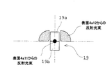
したがって、図3に示すように、目的表面4a11で反射された光は、ほぼ点に近い状態に集光して2分割フォトディテクター19に入射し、2分割フォトディテクター19の双方の受光部19a,19bで均等な光量が検出される。一方、目的表面4a11に対向する表面4a12で反射された光は、結像しない状態で2分割フォトディテクター19側に向かうが、そのすべてが、2分割フォトディテクター19から外れた位置を通る。
Therefore, as shown in FIG. 3, the light reflected by the target surface 4a11 is condensed in a state almost close to a point and enters the two-divided
このようにして、被検物4の目的表面4a11からの反射光だけを受光した2分割フォトディテクター19は、前記反射光の光量情報を捉え、焦点合わせ信号として不図示の制御部へ出力する。そして、この制御部はこの焦点合わせ信号に基づき、(A−B)/(A+B)なる評価関数を計算する。
In this way, the two-divided
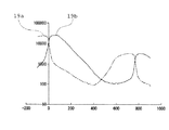
焦点検出装置3における2分割フォトディテクター19によって検出される光量変化の一例を図5のグラフに示す。また、図6に図5のデータに基づいて行った評価関数計算値の一例をグラフに示す。図6のグラフにおいて、横軸は被検物4と対物レンズの相対距離、縦軸は焦点合わせ評価値である。焦点合わせは、この評価関数値が0となるように駆動部10を介して対物レンズ6を上下させる。評価関数計算値が0となる位置に対物レンズ6が移動したときに対物レンズ6の焦点が被検物4の目的表面4a11に位置し合焦が達成される。これにより、ある一つの対物レンズについての焦点合わせは完了する。なお、この焦点合わせの原理は基本的には従来行われているものと同じである。
An example of the change in the amount of light detected by the two-divided
次に、被検物を別の倍率で観察、撮像するために対物レンズが交換された場合の焦点検出について説明する。
例えば、図4に示すように観察倍率を大きくするために対物レンズ6よりも大きな倍率の対物レンズ6’に交換した場合、倍率の大きな対物レンズは一般に瞳径が小さいので、光束入射位置調節手段21によって反射鏡21aと反射鏡21bの間隔を調節して狭くすることによって、焦点検出用光束が交換された対物レンズ6’の瞳22’の径に応じた瞳22’内の所定位置に入射するように調節される。一方で、倍率の小さな対物レンズを使用する場合には、反射鏡21aと反射鏡21bの間隔を広くすることによって、対物レンズの瞳径に応じた所定位置に入射するように調整する。
なお、この調整は対物レンズに対応させて自動的に行われるようにしてもよく、あるいは手動で行ってもよい。そして、反射鏡21aと反射鏡21bからの焦点検出光束がそれぞれ調節されたならば、上記した焦点合わせを行い対物レンズ6’を移動させ、対物レンズ6’の焦点が被検物4の目的表面4a11に位置し合焦が達成されるようにする。
Next, focus detection when the objective lens is exchanged for observing and imaging the test object at different magnifications will be described.
For example, as shown in FIG. 4, when the objective lens 6 'is larger than the
This adjustment may be performed automatically in correspondence with the objective lens, or may be performed manually. Then, when the focus detection light beams from the reflecting
このように本実施形態の焦点検出装置によれば、焦点検出用光源17から発した光は、遮光手段16を介してサンプル容器底面部4a1に照射され、目的としない側の表面からの反射光が排除されるので、焦点検出用光源17から発せられて目的表面4a11からの反射する光だけを、光検出器17で検出できる。このため、この目的としない側の表面からの反射光が外乱光として、焦点合わせ信号に悪影響を及ぼすことなく、高精度な焦点合わせを行うことができるようになる。
As described above, according to the focus detection apparatus of the present embodiment, the light emitted from the focus
さらに、光束位置調節手段を独立した2枚の反射鏡によって、焦点検出用光束を2つの光束に分割しているため、分割する各々の光束の反射光路をそれぞれ独立して調整できることとなる。 Further, since the focus detection light beam is divided into two light beams by two independent reflecting mirrors, the reflected light path of each of the divided light beams can be adjusted independently.
本発明の焦点検出装置は、例えば、自動化した顕微観察装置を用いて多数の細胞の画像を取得し、取得した画像を解析することにより統計解析結果を得ることが求められる分野に有用である。 The focus detection apparatus of the present invention is useful, for example, in a field where it is required to obtain a statistical analysis result by acquiring images of a large number of cells using an automated microscope observation apparatus and analyzing the acquired images.
1 顕微鏡本体
2 落射照明装置
3 焦点検出装置
3’ 焦点検出用ユニット
4 被検物
4a マイクロプレート
4b 培養液
4a1 底面部
4a11 表面部、目的表面
4a12 対向する表面
5 XYステージ
6 対物レンズ
6’ 大きな倍率の対物レンズ
7 ハーフミラー
8 結像レンズ
9 CCDカメラ
10 駆動部
11 光源
12 集光レンズ
13 結像レンズ
14 偏光ビームスプリッタ
15 λ/4板
16 遮光部材
17 焦点検出用光源、レーザダイオード
18 コリメートレンズ
19 光検出器、2分割フォトダイオード
19a 受光部
19b 受光部
20 ハーフミラー
21 光束入射位置調節手段
21a 反射鏡
21b 反射鏡
22 対物レンズの入射瞳、瞳
22’ 大きな対物レンズの瞳
DESCRIPTION OF
Claims (4)
前記対物レンズの瞳位置における前記焦点検出用光束の入射位置を該対物レンズの瞳径に応じた該瞳内の所定位置に調節可能な光束入射位置調節手段を備え、該光束入射位置調節手段は、少なくとも2つの反射鏡を含み、
前記光束入射位置調節手段が、前記焦点検出用光束を光軸に対称に分離し、
前記2つの反射鏡は、前記焦点検出用光束の光軸を中心として対称な位置に配置されており、
前記光束入射位置調節手段が、前記2つの反射鏡の間隔を、前記光軸を中心とした対称な位置を保ったまま調整することによって、該分離した2つの光束の間隔を調整することを特徴とした焦点検出装置。 A focus detection device that performs focusing by projecting a focus detection light beam onto a sample surface through an objective lens,
A light beam incident position adjusting means capable of adjusting an incident position of the focus detection light beam at a pupil position of the objective lens to a predetermined position in the pupil according to a pupil diameter of the objective lens; , it looks including at least two of the reflecting mirror,
The light beam incident position adjusting means separates the focus detection light beam symmetrically with respect to the optical axis,
The two reflecting mirrors are arranged at symmetrical positions around the optical axis of the focus detection light beam,
The light beam incident position adjusting means adjusts the distance between the two separated light beams by adjusting the distance between the two reflecting mirrors while maintaining a symmetrical position around the optical axis. Focus detection device.
前記光束入射位置調節手段は、前記透明基板における第1又は第2の表面のうち一方の表面近傍に前記対物レンズの焦点が位置するときに、該一方の表面からの反射光が前記2つの受光部に入射するとともに、他方の表面からの反射光が前記第2の仮想平面で分割したときの一方の領域における当該領域に配置された受光部を外れた領域を通るような該対物レンズの瞳内の所定位置に、該対物レンズの瞳位置における前記焦点検出用光束の入射位置が調節可能に構成されていることを特徴とする請求項1〜3のいずれかに記載の焦点検出装置。 The focus detection device includes the objective lens, a point light source that emits illumination light for generating a focusing signal for the transparent substrate and irradiates the transparent light through the objective lens, and light of the illumination light in the luminous flux of the illumination light. A light shielding member that shields a light beam passing through one region when divided into two by a first virtual plane along the axis, and a second virtual plane along the optical axis of the light reflected by the transparent substrate, and symmetrical A light detector having two light receiving portions arranged, and the first or second of the transparent substrate based on the amount of reflected light from the transparent substrate detected through the two light receiving portions, respectively. Focus the objective lens on the surface of
The light beam incident position adjusting means is configured to receive reflected light from the first surface when the focal point of the objective lens is located in the vicinity of one of the first and second surfaces of the transparent substrate. And the pupil of the objective lens that passes through a region outside the light receiving unit arranged in the one region when the reflected light from the other surface is divided by the second virtual plane. The focus detection device according to claim 1, wherein an incident position of the focus detection light beam at a pupil position of the objective lens is adjustable at a predetermined position .
Priority Applications (1)
| Application Number | Priority Date | Filing Date | Title |
|---|---|---|---|
| JP2009154025A JP5400499B2 (en) | 2009-06-29 | 2009-06-29 | Focus detection device |
Applications Claiming Priority (1)
| Application Number | Priority Date | Filing Date | Title |
|---|---|---|---|
| JP2009154025A JP5400499B2 (en) | 2009-06-29 | 2009-06-29 | Focus detection device |
Publications (3)
| Publication Number | Publication Date |
|---|---|
| JP2011008189A JP2011008189A (en) | 2011-01-13 |
| JP2011008189A5 JP2011008189A5 (en) | 2012-08-02 |
| JP5400499B2 true JP5400499B2 (en) | 2014-01-29 |
Family
ID=43564894
Family Applications (1)
| Application Number | Title | Priority Date | Filing Date |
|---|---|---|---|
| JP2009154025A Expired - Fee Related JP5400499B2 (en) | 2009-06-29 | 2009-06-29 | Focus detection device |
Country Status (1)
| Country | Link |
|---|---|
| JP (1) | JP5400499B2 (en) |
Families Citing this family (2)
| Publication number | Priority date | Publication date | Assignee | Title |
|---|---|---|---|---|
| JP2021036820A (en) * | 2019-09-03 | 2021-03-11 | シンフォニアテクノロジー株式会社 | Cell observation device |
| CN113030090B (en) * | 2021-03-22 | 2024-08-30 | 广东粤港澳大湾区黄埔材料研究院 | Microscope lock burnt system |
Family Cites Families (5)
| Publication number | Priority date | Publication date | Assignee | Title |
|---|---|---|---|---|
| JPS5863906A (en) * | 1981-10-14 | 1983-04-16 | Olympus Optical Co Ltd | Focused position detector for microscope |
| JPS62143010A (en) * | 1985-12-17 | 1987-06-26 | Olympus Optical Co Ltd | Focus detecting device |
| JPS63163313A (en) * | 1986-12-25 | 1988-07-06 | Mitaka Koki Kk | Focus positioning device |
| JPH0244709U (en) * | 1988-09-20 | 1990-03-28 | ||
| JP3237023B2 (en) * | 1992-05-08 | 2001-12-10 | 株式会社ニコン | Position detection device |
-
2009
- 2009-06-29 JP JP2009154025A patent/JP5400499B2/en not_active Expired - Fee Related
Also Published As
| Publication number | Publication date |
|---|---|
| JP2011008189A (en) | 2011-01-13 |
Similar Documents
| Publication | Publication Date | Title |
|---|---|---|
| JP2008276070A (en) | Magnifying image pickup apparatus | |
| JP6662529B2 (en) | System and method for continuous asynchronous autofocus of optics | |
| TWI710799B (en) | Systems and methods for improved focus tracking using blocking structures | |
| CN102483509A (en) | Three-dimensional directional drift control device and microscope device | |
| US9366849B2 (en) | Microscope system and method for microscope system | |
| US20130100461A1 (en) | Methods and apparatuses for position and force detection | |
| US10254526B2 (en) | Microscope | |
| JP5620502B2 (en) | Autofocus device | |
| CN114112322A (en) | Microscope focus offset measurement method based on differential confocal | |
| KR20150044291A (en) | Automatic focus control apparatus and automatic focus control method using the same | |
| JP5400499B2 (en) | Focus detection device | |
| US20070012859A1 (en) | Focus detection apparatus | |
| US10634895B2 (en) | Microscope apparatus, automatic focusing device, and automatic focusing method | |
| JP2009128152A (en) | Evanescent wave generator and observation device using the same | |
| JP2012212018A (en) | Focal point maintenance device and microscope device | |
| JP2008267842A (en) | Organism observation container, biological microscope using the same, and organism observation apparatus | |
| US11971531B2 (en) | Method and microscope for determining the thickness of a cover slip or slide | |
| JP5394718B2 (en) | Microscopic observation equipment | |
| JP2013088570A (en) | Microscope apparatus | |
| KR20220072100A (en) | Reflective incoherent illumination microscopy with LED array | |
| JPH09325278A (en) | Confocal type optical microscope | |
| JP5009141B2 (en) | Focus detection apparatus and focusing method using the same | |
| JP2007212171A (en) | Fluorescence detector | |
| JP2012141452A (en) | Automatic focus mechanism and microscope device | |
| US20240319487A1 (en) | Microscope and method for autofocusing |
Legal Events
| Date | Code | Title | Description |
|---|---|---|---|
| A521 | Request for written amendment filed |
Free format text: JAPANESE INTERMEDIATE CODE: A523 Effective date: 20120619 |
|
| A621 | Written request for application examination |
Free format text: JAPANESE INTERMEDIATE CODE: A621 Effective date: 20120619 |
|
| A977 | Report on retrieval |
Free format text: JAPANESE INTERMEDIATE CODE: A971007 Effective date: 20130228 |
|
| A131 | Notification of reasons for refusal |
Free format text: JAPANESE INTERMEDIATE CODE: A131 Effective date: 20130723 |
|
| A521 | Request for written amendment filed |
Free format text: JAPANESE INTERMEDIATE CODE: A523 Effective date: 20130912 |
|
| RD02 | Notification of acceptance of power of attorney |
Free format text: JAPANESE INTERMEDIATE CODE: A7422 Effective date: 20130912 |
|
| TRDD | Decision of grant or rejection written | ||
| A01 | Written decision to grant a patent or to grant a registration (utility model) |
Free format text: JAPANESE INTERMEDIATE CODE: A01 Effective date: 20131009 |
|
| A61 | First payment of annual fees (during grant procedure) |
Free format text: JAPANESE INTERMEDIATE CODE: A61 Effective date: 20131025 |
|
| R151 | Written notification of patent or utility model registration |
Ref document number: 5400499 Country of ref document: JP Free format text: JAPANESE INTERMEDIATE CODE: R151 |
|
| S531 | Written request for registration of change of domicile |
Free format text: JAPANESE INTERMEDIATE CODE: R313531 |
|
| R350 | Written notification of registration of transfer |
Free format text: JAPANESE INTERMEDIATE CODE: R350 |
|
| R250 | Receipt of annual fees |
Free format text: JAPANESE INTERMEDIATE CODE: R250 |
|
| R250 | Receipt of annual fees |
Free format text: JAPANESE INTERMEDIATE CODE: R250 |
|
| R250 | Receipt of annual fees |
Free format text: JAPANESE INTERMEDIATE CODE: R250 |
|
| R250 | Receipt of annual fees |
Free format text: JAPANESE INTERMEDIATE CODE: R250 |
|
| LAPS | Cancellation because of no payment of annual fees | ||
| S111 | Request for change of ownership or part of ownership |
Free format text: JAPANESE INTERMEDIATE CODE: R313111 |
|
| R371 | Transfer withdrawn |
Free format text: JAPANESE INTERMEDIATE CODE: R371 |
|
| S111 | Request for change of ownership or part of ownership |
Free format text: JAPANESE INTERMEDIATE CODE: R313111 |
|
| R371 | Transfer withdrawn |
Free format text: JAPANESE INTERMEDIATE CODE: R371 |