US8070404B1 - Bonding fastener assembly for electrical grounding - Google Patents
Bonding fastener assembly for electrical grounding Download PDFInfo
- Publication number
- US8070404B1 US8070404B1 US12/386,710 US38671009A US8070404B1 US 8070404 B1 US8070404 B1 US 8070404B1 US 38671009 A US38671009 A US 38671009A US 8070404 B1 US8070404 B1 US 8070404B1
- Authority
- US
- United States
- Prior art keywords
- washer
- head
- nut
- fastener assembly
- fastener
- Prior art date
- Legal status (The legal status is an assumption and is not a legal conclusion. Google has not performed a legal analysis and makes no representation as to the accuracy of the status listed.)
- Expired - Fee Related, expires
Links
- 230000000717 retained effect Effects 0.000 claims description 12
- 238000000034 method Methods 0.000 claims description 4
- 239000003973 paint Substances 0.000 description 9
- 239000011248 coating agent Substances 0.000 description 6
- 238000000576 coating method Methods 0.000 description 6
- 239000010953 base metal Substances 0.000 description 5
- 238000005260 corrosion Methods 0.000 description 4
- 238000009434 installation Methods 0.000 description 4
- 230000014759 maintenance of location Effects 0.000 description 4
- 239000002184 metal Substances 0.000 description 4
- 230000007797 corrosion Effects 0.000 description 3
- 230000000149 penetrating effect Effects 0.000 description 3
- 239000003963 antioxidant agent Substances 0.000 description 2
- 235000006708 antioxidants Nutrition 0.000 description 2
- 230000000712 assembly Effects 0.000 description 2
- 238000000429 assembly Methods 0.000 description 2
- 239000004020 conductor Substances 0.000 description 2
- 238000012986 modification Methods 0.000 description 2
- 230000004048 modification Effects 0.000 description 2
- 230000035515 penetration Effects 0.000 description 2
- 229910000831 Steel Inorganic materials 0.000 description 1
- 239000002519 antifouling agent Substances 0.000 description 1
- 230000003078 antioxidant effect Effects 0.000 description 1
- 230000015572 biosynthetic process Effects 0.000 description 1
- 238000006073 displacement reaction Methods 0.000 description 1
- 230000002452 interceptive effect Effects 0.000 description 1
- 238000003754 machining Methods 0.000 description 1
- 239000000463 material Substances 0.000 description 1
- 230000013011 mating Effects 0.000 description 1
- 239000007769 metal material Substances 0.000 description 1
- 239000012255 powdered metal Substances 0.000 description 1
- 230000002028 premature Effects 0.000 description 1
- 238000004080 punching Methods 0.000 description 1
- 238000010079 rubber tapping Methods 0.000 description 1
- 229910001220 stainless steel Inorganic materials 0.000 description 1
- 239000010935 stainless steel Substances 0.000 description 1
- 239000010959 steel Substances 0.000 description 1
- 239000000126 substance Substances 0.000 description 1
Images


Classifications
-
- F—MECHANICAL ENGINEERING; LIGHTING; HEATING; WEAPONS; BLASTING
- F16—ENGINEERING ELEMENTS AND UNITS; GENERAL MEASURES FOR PRODUCING AND MAINTAINING EFFECTIVE FUNCTIONING OF MACHINES OR INSTALLATIONS; THERMAL INSULATION IN GENERAL
- F16B—DEVICES FOR FASTENING OR SECURING CONSTRUCTIONAL ELEMENTS OR MACHINE PARTS TOGETHER, e.g. NAILS, BOLTS, CIRCLIPS, CLAMPS, CLIPS OR WEDGES; JOINTS OR JOINTING
- F16B41/00—Measures against loss of bolts, nuts, or pins; Measures against unauthorised operation of bolts, nuts or pins
- F16B41/002—Measures against loss of bolts, nuts or pins
-
- F—MECHANICAL ENGINEERING; LIGHTING; HEATING; WEAPONS; BLASTING
- F16—ENGINEERING ELEMENTS AND UNITS; GENERAL MEASURES FOR PRODUCING AND MAINTAINING EFFECTIVE FUNCTIONING OF MACHINES OR INSTALLATIONS; THERMAL INSULATION IN GENERAL
- F16B—DEVICES FOR FASTENING OR SECURING CONSTRUCTIONAL ELEMENTS OR MACHINE PARTS TOGETHER, e.g. NAILS, BOLTS, CIRCLIPS, CLAMPS, CLIPS OR WEDGES; JOINTS OR JOINTING
- F16B39/00—Locking of screws, bolts or nuts
- F16B39/22—Locking of screws, bolts or nuts in which the locking takes place during screwing down or tightening
- F16B39/28—Locking of screws, bolts or nuts in which the locking takes place during screwing down or tightening by special members on, or shape of, the nut or bolt
- F16B39/282—Locking by means of special shape of work-engaging surfaces, e.g. notched or toothed nuts
-
- F—MECHANICAL ENGINEERING; LIGHTING; HEATING; WEAPONS; BLASTING
- F16—ENGINEERING ELEMENTS AND UNITS; GENERAL MEASURES FOR PRODUCING AND MAINTAINING EFFECTIVE FUNCTIONING OF MACHINES OR INSTALLATIONS; THERMAL INSULATION IN GENERAL
- F16B—DEVICES FOR FASTENING OR SECURING CONSTRUCTIONAL ELEMENTS OR MACHINE PARTS TOGETHER, e.g. NAILS, BOLTS, CIRCLIPS, CLAMPS, CLIPS OR WEDGES; JOINTS OR JOINTING
- F16B2200/00—Constructional details of connections not covered for in other groups of this subclass
- F16B2200/93—Fastener comprising feature for establishing a good electrical connection, e.g. electrostatic discharge or insulation feature
Definitions
- the present invention relates to an attachment or fastening system for use in securing two or more structures and, more particularly, to a fastening system for providing electrical conductivity through the secured structures after attachment.
- grounding through multiple racks is generally required. Since many racks have a protective paint coating, the direct attachment using conventional nuts and bolts is not, in some cases, sufficient to provide an electrical connection. As such, in order to provide adequate grounding, separate grounding wires are typically used to provide electrical continuity. One end of the grounding wire is attached to a stud or post and the other end is attached to a grounding bus bar mounted to the rack. While this type of attachment is adequate for providing electrical grounding, the attachment of the grounding wires is time consuming and subject to error should the ground connection not be properly completed.
- a product that was recently introduced by Panduit Corporation is referred to as the Tapped Rail Bonding Stud Kit and includes a nut and bolt arrangement with serrations or teeth formed integral to and on the bottom of the nut and bolt. That product is described in detail in U.S. Patent Publication No. 2006/0257229.
- Panduit product does address the problem for breaking through the paint layer to reach the base metal
- Applicant has determined that the product negatively impacts the appearance of the components and can create a corrosion source since the serrations are designed to remove a complete circular ring of paint exposing the bare metal.
- the ring of bare metal is susceptible to corrosion unless an anti-oxidant is applied.
- application of anti-oxidants is an additional assembly step and can be difficult to apply.
- a fastener assembly includes a fastener with a head having a first or top surface for engagement by an attachment tool, and second or bottom surface opposite the first surface.
- a shaft extends out from the second surface of the head and is threaded along at least a portion of the shaft.
- An annular washer is rotatably disposed about the shaft and rotatable relative to the second surface of the fastener head.
- the washer a planar body with an inner diameter, an outer diameter, a first surface and a second surface opposite the first surface, the first surface of the washer being positioned adjacent to the second surface of the head.
- a plurality of substantially identical conical projections extend out from the second surface of the washer and are formed integrally therewith.
- the fastener is a bolt and the assembly further includes a nut.
- the nut has a first surface for engagement by an attachment tool, and a substantially flat second surface. The second surface faces the second surface of the head and the second surface of the annular washer.
- a second annular washer is disposed about the shaft and rotatable relative to the second surface of the nut and the shaft.
- the second washer has an inner diameter, an outer diameter, a first surface and a second surface opposite the first surface.
- the first surface of the washer is positioned adjacent to the second surface of the nut.
- a plurality of substantially identical conical projections extend out from the second surface of the second washer and are formed integrally therewith.
- FIG. 1 is a perspective view of a portion of two adjacent racks being attached together with a bonding fastener assembly according to the present invention.
- FIG. 2 is an isometric view of a bonding fastener assembly according to one embodiment of the invention.
- FIG. 3 is an isometric view of the bonding fastener assembly of FIG. 2 disassembled.
- FIG. 4 is a side view of the bonding fastener assembly of FIG. 2 .
- FIG. 5 is a top view of the spiked washer according to one embodiment of the invention.
- FIG. 6 is a side view of the spiked washer of FIG. 5 .
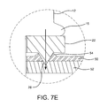
- FIGS. 7A-7E illustrate the how the present invention penetrates the paint coating to form an electrical connection.
- FIG. 8 is a cross-section of a fastener and nut illustrating the retention of the spiked washers in one embodiment.
- FIG. 8A is an enlargement of a portion of the washer.
- FIGS. 9A-9C illustrate different shape spikes for the washer of FIG. 2 .
- FIG. 1 illustrates one embodiment of the bonding fastener assembly 10 of the present invention as it is contemplated for use in attaching two rack assemblies.
- the bonding fastener assembly 10 includes a fastener 12 with a head 14 , including a top surface 16 and bottom surface 18 , a shaft 20 and a spiked washer 22 .
- the top surface 16 of the head 14 has a conventional configuration designed to be engaged with a common installation tool.
- the head may include a recess for receiving a Phillips head screwdriver, or may have a polygonal shape for engagement with a suitable ratchet.
- the various configurations that the top surface can be formed in are well known to those skilled in the art and, therefore, no further discussion is needed.
- the bottom surface 18 of the head 14 is preferably flat.
- the shaft 20 is integral with the head 14 and extends from the second surface.
- the shaft 20 includes threads on at least a portion of its surface for engagement with a mating nut or for self tapping into a metal component in a conventional manner.
- the spiked washer 22 is shown in detail in FIGS. 2-6 .
- the spiked washer includes a substantially planar annular ring base 24 with a plurality of conical protrusions or spikes 26 projecting out from one face 28 of the washer 22 .
- the opposite face 30 does not have any protrusions and, instead, provides a relatively smooth surface for the bottom surface 18 of the head to slide along as will be explained in more detail below.
- the location and number of the spikes 26 may vary, although the location and number should be chosen so as to provide reliable displacement of and penetration into the painted surface during use and to provide sufficient electrical conductivity through the connection. Substantially even spacing of the spikes around the bottom surface will assist in the washer seating properly with the connecting surface (i.e., lying flat on top of the surface being connected.)
- spikes 26 there are approximately six spikes 26 formed on the bottom surface, evenly spaced about a medial circumference 32 of the washer 22 with a median diameter of approximately 0.50 inches for the illustrated washer 22 that has an overall outer diameter of 0.680 inches and an inner diameter of 0.325 inches.
- the location of the spikes 26 at this position provides more reliability that the loads imposed on the washer during tightening of the fastener will translate substantially directly through the spikes as an axial piercing force into the painted surface, thereby displacing and penetrating the paint locally and embedding the spikes into the underlying metal material.
- the spikes are equally spaced about a circumference that is radially inward but close to the outer edges of the washer.
- the washer 22 is made from stainless steel with a thickness of approximately 1/16 th inch. This is sufficiently thick enough to prevent deforming of the washer during attachment. Deformation is not desired since it can cause the spikes to not embed properly and, thus cause the washer to spin as it is tightened.
- the spikes 26 are preferably formed integral with the washer 22 .
- the washers 22 are cast or formed in a die with the spikes 26 from a high strength electrically conductive material, such as steel, powdered metal, or other well known electrically conductive materials. It is also contemplated that the washer could be formed using a stamping or machining process.
- the washer 22 should be manufactured with a suitable hardness and stiffness to achieve the desired penetration. If the spikes are too hard, they can break. However, if the spikes are too soft they may deform during tightening and fail to penetrate into the base metal. Thus, proper hardening is needed. This can be achieved though a hardening or heat treat process after the spikes are formed.
- the washer is manufactured such that the spikes have a Rockwell hardness of between 30 and 80 (on the C scale) with a more preferred Rockwell hardness of approximately 58.
- the washer 22 is formed using a die punching process. A blank washer is placed on a die with appropriately shaped cavities in the die that have a contour configured to form the spikes. A punch is pressed down onto the opposite side of the washer forcing a portion of the material of the washer to flow into the cavities, thereby forming the spikes.
- the spikes 26 preferably have a height H from the flat face 28 of about 0.062 inches and have a width W of about 0.072 inches at the flat surface, tapering preferably uniformly to the tip 34 .
- the cone has an inclusive angle ⁇ of approximately 60 degrees.
- the shape and size of the spikes may vary, however the spikes must have a sufficiently sharp tip or edge to sever the painted surface.
- the inclusive angle must be sufficiently small to provide the sharp piercing point, while still providing sufficient strength so as not to break during installation.
- a preferred angle ⁇ in the present invention is between about 20 degrees and 120 degrees. More preferably, the inclusive angle is between 30 degrees and 80 degrees. Any narrower than 20 degrees could lead to premature breakage of the spike. Any larger than 120 degrees can lead to the spike failing to sufficiently penetrate the painted layer.
- two spiked washers 22 are preferably used, one on either side of the installation with the spikes 26 facing one another.
- the assembly when tightened, will break through the painted surfaces from both sides, thus providing electrical continuity.
- the fastener may be a screw or other fastener, instead of the illustrated bolt.
- the washer 22 is attached to at least the bolt 12 , yet free to rotate about the shaft.
- a retention clip may be attached to the washer 22 or the shaft 20 and designed to retain the washer on the shaft so that it cannot readily slip off. The attachment would, however, permit the washer to rotate relative to the head so that when the head is tightened, the washer does not rotate.
- the shaft or shank 20 of the bolt preferably includes a non-threaded portion adjacent to the head 14 .
- the washer 22 is free to rotate about the non-threaded portion.
- the washer 22 may be retained on the non-threaded portion simply by threading the washer onto the shaft until it reaches the non-threaded portion.
- the spiked washer is placed on the non-threaded portion prior to threading of the shaft 20 .
- Threads are then formed on the shaft 22 in a conventional manner. The formation of the threads results in the threads having an outer diameter that is greater than the diameter of the non-threaded portion and the inner diameter of the washer 22 . As such, the washer 22 is retained on the bolt.
- the non-threaded portion of the shaft has a length of approximately 5/32 nd inch and the washer 22 has a thickness of approximately 1/16 th inch, thus resulting in the washer having approximately 3/32 nd inch gap to float along the shaft 20 .
- a second washer 22 is also preferably retained on the nut 36 .
- this is achieved by forming the nut with an annular extension with a diameter that is less than the inner diameter of the washer.
- the washer 22 is placed on the extension and the extension is then swaged outward to form a retention lip.
- the retention lip retains the washer onto the nut while permitting the washer to rotate relative to the nut.
- the washer on the nut is formed with a recessed inner ring with a thickness of approximately 1/32 nd inch and a diameter of approximately 7/16 th inch.
- the annular extension is swaged into a lip that preferably sits within the recessed area.
- the lip is preferably raised slightly off of the recessed area so that the washer can be rotated relative to the nut while still retained by the lip from separating.
- FIG. 8 One of the unique and unexpected aspects of the invention shown in FIG. 8 is the ability to tighten a bolted assembly from only one side. More particularly, the user inserts the bolted attachment through a hole between two components. The nut, including its retained washer, is threaded onto the opposite end of the shaft until the spikes engage the surface of the second component. At this point, since the washer adjacent to the nut is attached to the nut, the tightening of the bolt causes the nut to bear into the washer. The spikes on the washer inhibit rotation of the washer and nut, thus holding the nut in place as the bolt is tightened. Hence, the bolted assembly can be tightened from one side, making attachment of rack assemblies easier and quicker.
- a round nut could be used so as to reduce the desire by the installer to use a tool and potentially damage the painted surface. Also, it may be desirable to form the nut and spiked washer as a integral unit or eliminate the nut altogether and simply thread the inner diameter of the washer.
- FIGS. 7A-7E the installation of a fastener according to the present invention is shown.
- FIG. 7A shows the initial touchdown of the spiked washer 22 onto the painted surface 50 .
- FIG. 7B shows the floating gap between the head 14 and the washer.
- Further tightening of the fastener causes the spikes be begin to penetrate the painted surface 20 , displacing the paint 54 ( FIG. 7C ).
- FIG. 7E illustrates how the displaced painted coating 54 forms a seal against the side surfaces of the spikes 26 .
- the preferred embodiment is a conical shaped spike, such as the one shown in FIG. 9A
- a pyramidal (three, four or more sided) structure can be used as the spike provided the tip is designed to penetrate and displace the painted coating as it extends into the base metal.
- FIG. 9C shows an example of a pyramidal shaped spike.
- the spike can instead form a knife edge, such as the linear edge shown in FIG. 9B . The knife edge is designed to dig into the painted coating during tightening, displacing the paint and penetrating into the base metal.
- the bolt head 14 and the nut 36 it is preferable for the bolt head 14 and the nut 36 to have a base portion 15 that is flared out ward as shown in FIG. 8 .
- the penetrating of the painted surface by the spikes is more efficient since less force it transmitted to the surrounding portion of the washer.
- the present invention provides a system for use in “ganging” equipment enclosures together, while at the same time providing a continuous and reliable path for electrical ground faults, high frequency leakage currents, and electrically bonding multiple enclosures together to form an extension of the “ground plane”.
- the present invention can also be used to electrically bond loose sheet metal accessories such as doors, tops, sides, etc. It eliminates the need to mask studs or screw landings pre-paint.
Landscapes
- Engineering & Computer Science (AREA)
- General Engineering & Computer Science (AREA)
- Mechanical Engineering (AREA)
- Bolts, Nuts, And Washers (AREA)
Abstract
Description
Claims (19)
Priority Applications (1)
| Application Number | Priority Date | Filing Date | Title |
|---|---|---|---|
| US12/386,710 US8070404B1 (en) | 2008-11-06 | 2009-04-21 | Bonding fastener assembly for electrical grounding |
Applications Claiming Priority (2)
| Application Number | Priority Date | Filing Date | Title |
|---|---|---|---|
| US19854008P | 2008-11-06 | 2008-11-06 | |
| US12/386,710 US8070404B1 (en) | 2008-11-06 | 2009-04-21 | Bonding fastener assembly for electrical grounding |
Publications (1)
| Publication Number | Publication Date |
|---|---|
| US8070404B1 true US8070404B1 (en) | 2011-12-06 |
Family
ID=45034339
Family Applications (1)
| Application Number | Title | Priority Date | Filing Date |
|---|---|---|---|
| US12/386,710 Expired - Fee Related US8070404B1 (en) | 2008-11-06 | 2009-04-21 | Bonding fastener assembly for electrical grounding |
Country Status (1)
| Country | Link |
|---|---|
| US (1) | US8070404B1 (en) |
Cited By (35)
| Publication number | Priority date | Publication date | Assignee | Title |
|---|---|---|---|---|
| US20120222381A1 (en) * | 2009-11-25 | 2012-09-06 | Rbpsp Pty Ltd. | Washer Assembly and Arcuate Threaded Fastener |
| US20130026331A1 (en) * | 2010-03-29 | 2013-01-31 | Harada Industry Co., Ltd. | Mounting bracket for antenna |
| US8777538B2 (en) | 2012-09-10 | 2014-07-15 | Renewable Energy Holdings, Llc | Bonding fastener with environmental seals |
| US8997336B2 (en) | 2012-09-10 | 2015-04-07 | Renewable Energy Holdings, Llc | Air-tight and water-tight electrical bonding device |
| US20150333418A1 (en) * | 2014-05-15 | 2015-11-19 | Airbus Operations Gmbh | Contact Sealing Ring, Electrical Contact Point And Method For Contacting Electrically Conductive Components |
| US9239073B2 (en) * | 2014-01-31 | 2016-01-19 | Kaoru Taneichi | Fastening device |
| US20160088759A1 (en) * | 2014-09-18 | 2016-03-24 | Denso Corporation | Electronic device |
| US9520657B2 (en) * | 2014-07-31 | 2016-12-13 | Hubbell Incorporated | Electrical terminal |
| US20170063300A1 (en) * | 2015-08-31 | 2017-03-02 | Ironridge, Inc. | Apparatus for Securing a Solar Panel Rail Guide to a Support Bracket |
| USD803266S1 (en) * | 2016-04-08 | 2017-11-21 | Enrique J. Baiz | Solenoid cover |
| USD803267S1 (en) * | 2016-04-08 | 2017-11-21 | Enrique J. Baiz | Solenoid cover |
| US9865938B2 (en) * | 2012-07-05 | 2018-01-09 | Ironridge, Inc. | Apparatus for electrically bonding a solar array |
| WO2018023154A1 (en) * | 2016-08-02 | 2018-02-08 | Flexistrut Building Services Pty Ltd | Fixing device |
| EP3367767A1 (en) | 2017-02-27 | 2018-08-29 | Middle Atlantic Products Inc. | Vertical wall mount host enclosure |
| US10103468B2 (en) * | 2015-03-06 | 2018-10-16 | Kd&E Solar, Llc. | Coating displacement electrical connecting device and related methods |
| US10218306B2 (en) * | 2015-08-31 | 2019-02-26 | Ironridge, Inc. | Apparatus for securing a solar panel rail guide to a support bracket |
| US10246937B2 (en) * | 2016-12-15 | 2019-04-02 | Glide Rite Corporation | Barrel bolt fastener assembly |
| US10312855B2 (en) * | 2016-05-31 | 2019-06-04 | Ironridge, Inc. | Bracket mount for securing micro-inverters and power optimizers to solar panel arrays |
| FR3081194A1 (en) * | 2018-05-15 | 2019-11-22 | Psa Automobiles Sa | ASSEMBLY BY FIXING SCREW OF A FIRST PIECE FRAMING A SECOND PIECE |
| US10577825B1 (en) * | 2015-07-30 | 2020-03-03 | Ameristar Perimeter Security Usa Inc. | Conductive barrier |
| US20200116191A1 (en) * | 2018-10-10 | 2020-04-16 | Unirac Inc. | Corrugated Washer for Use with a Corrugated L-Foot Mounting Bracket for Mounting Solar Panels to a Roof |
| DE102019202313A1 (en) * | 2019-02-20 | 2020-08-20 | Brühl Safety GmbH | Fastening strap for fastening a security fence panel and security fence |
| DE102019202316A1 (en) * | 2019-02-20 | 2020-08-20 | Brühl Safety GmbH | Connection of a security fence field to a fence post or other fence support and security fence |
| US20210119355A1 (en) * | 2019-10-17 | 2021-04-22 | Production Spring, LLC | Electrical ground strap assembly providing increased point of contact between a terminal and a bolt |
| US11121484B2 (en) | 2012-07-05 | 2021-09-14 | Ironridge, Inc. | Assembly for clamping and grounding objects |
| FR3115080A1 (en) * | 2020-10-14 | 2022-04-15 | Centre Technique des Industries Mécaniques | friction spacer |
| US11362446B2 (en) * | 2017-08-08 | 2022-06-14 | Cochrane Steel Products (Pty) Ltd | Earthing technique |
| US11512730B2 (en) * | 2020-05-15 | 2022-11-29 | Gm Cruise Holdings Llc | Stud assembly for high current applications |
| US20230121175A1 (en) * | 2019-11-28 | 2023-04-20 | Meishan Crrc Fastening System Co., Ltd | Pulling rivet for fastening connection of conductive material |
| US11735837B2 (en) | 2019-10-17 | 2023-08-22 | Production Spring, LLC | Electrical ground strap assemblies providing increased point of contact between a terminal and a bolt |
| JP2023174208A (en) * | 2022-05-27 | 2023-12-07 | 岡野機工株式会社 | bush |
| US20240017626A1 (en) * | 2022-07-14 | 2024-01-18 | Dana Automotive Systems Group, Llc | Overmolded mechanical fastener with integrated sealing |
| US20240097358A1 (en) * | 2022-09-16 | 2024-03-21 | Ford Global Technologies, Llc | Electric ground assembly for grounding a vehicle component |
| US20240113376A1 (en) * | 2022-09-30 | 2024-04-04 | Ford Global Technologies, Llc | Electrical ground assembly for grounding and fluidly sealing a vehicle component |
| US12009777B2 (en) | 2021-04-01 | 2024-06-11 | Kloeckner Metals Corporation | Solar panel rail |
Citations (13)
| Publication number | Priority date | Publication date | Assignee | Title |
|---|---|---|---|---|
| US296948A (en) * | 1884-04-15 | Nut-lock | ||
| US641376A (en) * | 1899-07-31 | 1900-01-16 | John S Doddridge | Nut-lock. |
| US643485A (en) * | 1899-05-09 | 1900-02-13 | Edwin L Edmondson | Nut-lock washer. |
| US2069402A (en) * | 1935-06-29 | 1937-02-02 | Eaton Mfg Co | Lock washer |
| US2271732A (en) * | 1938-10-04 | 1942-02-03 | Chappuis John Albert | Lock washer |
| US2372653A (en) * | 1940-04-19 | 1945-04-03 | Alan L Becket | Electrical terminal |
| US2523652A (en) * | 1948-02-05 | 1950-09-26 | Chester W Dowd | Shoe cleat assembly |
| US3761867A (en) * | 1972-01-19 | 1973-09-25 | Thomas & Betts Corp | Insulation and oxide piercing contact means |
| US5069589A (en) * | 1988-08-25 | 1991-12-03 | Lemke Stuart H | Stress plate for roof membrane fastener assembly |
| US5487685A (en) * | 1991-06-28 | 1996-01-30 | Ab Volvo | Electrical contract nut |
| US5658108A (en) * | 1993-11-22 | 1997-08-19 | Swick; E. Grant | Electrical connection terminal assembly and tilt washer |
| US6082942A (en) * | 1993-11-22 | 2000-07-04 | Swick; E. Grant | Electrical connection terminal assembly and tilt washer |
| US20060257229A1 (en) | 2005-05-16 | 2006-11-16 | Panduit Corp. | Bonding fastener |
-
2009
- 2009-04-21 US US12/386,710 patent/US8070404B1/en not_active Expired - Fee Related
Patent Citations (13)
| Publication number | Priority date | Publication date | Assignee | Title |
|---|---|---|---|---|
| US296948A (en) * | 1884-04-15 | Nut-lock | ||
| US643485A (en) * | 1899-05-09 | 1900-02-13 | Edwin L Edmondson | Nut-lock washer. |
| US641376A (en) * | 1899-07-31 | 1900-01-16 | John S Doddridge | Nut-lock. |
| US2069402A (en) * | 1935-06-29 | 1937-02-02 | Eaton Mfg Co | Lock washer |
| US2271732A (en) * | 1938-10-04 | 1942-02-03 | Chappuis John Albert | Lock washer |
| US2372653A (en) * | 1940-04-19 | 1945-04-03 | Alan L Becket | Electrical terminal |
| US2523652A (en) * | 1948-02-05 | 1950-09-26 | Chester W Dowd | Shoe cleat assembly |
| US3761867A (en) * | 1972-01-19 | 1973-09-25 | Thomas & Betts Corp | Insulation and oxide piercing contact means |
| US5069589A (en) * | 1988-08-25 | 1991-12-03 | Lemke Stuart H | Stress plate for roof membrane fastener assembly |
| US5487685A (en) * | 1991-06-28 | 1996-01-30 | Ab Volvo | Electrical contract nut |
| US5658108A (en) * | 1993-11-22 | 1997-08-19 | Swick; E. Grant | Electrical connection terminal assembly and tilt washer |
| US6082942A (en) * | 1993-11-22 | 2000-07-04 | Swick; E. Grant | Electrical connection terminal assembly and tilt washer |
| US20060257229A1 (en) | 2005-05-16 | 2006-11-16 | Panduit Corp. | Bonding fastener |
Non-Patent Citations (2)
| Title |
|---|
| Panduit Corp. Tinley Park , Illinois; Tapped Rail Bonding Stud Kits, Customer Drawing , No. C41700; Feb. 2007; 1 pg. |
| Tapped Rail Bonding Stud Kits-Panduit Network and Electrical Solutions; http://www.panduit.com/Products/ProductOverviews/ProductSearch/index.htm; Aug. 14, 2008; 1 pg. |
Cited By (56)
| Publication number | Priority date | Publication date | Assignee | Title |
|---|---|---|---|---|
| US8910449B2 (en) * | 2009-11-25 | 2014-12-16 | RPBSP Pty Ltd. | Washer assembly and arcuate threaded fastener |
| US20120222381A1 (en) * | 2009-11-25 | 2012-09-06 | Rbpsp Pty Ltd. | Washer Assembly and Arcuate Threaded Fastener |
| US20130026331A1 (en) * | 2010-03-29 | 2013-01-31 | Harada Industry Co., Ltd. | Mounting bracket for antenna |
| US12451624B2 (en) | 2012-07-05 | 2025-10-21 | Ironridge, Inc. | Assembly for clamping and grounding objects |
| US12062881B2 (en) | 2012-07-05 | 2024-08-13 | Ironridge, Inc. | Assembly for clamping and grounding objects |
| US11929583B2 (en) | 2012-07-05 | 2024-03-12 | Ironridge, Inc. | Assembly for clamping and grounding objects |
| US9865938B2 (en) * | 2012-07-05 | 2018-01-09 | Ironridge, Inc. | Apparatus for electrically bonding a solar array |
| US11121484B2 (en) | 2012-07-05 | 2021-09-14 | Ironridge, Inc. | Assembly for clamping and grounding objects |
| US11189941B2 (en) | 2012-07-05 | 2021-11-30 | Ironridge, Inc. | Assembly for clamping and grounding objects |
| US8997336B2 (en) | 2012-09-10 | 2015-04-07 | Renewable Energy Holdings, Llc | Air-tight and water-tight electrical bonding device |
| US9667013B2 (en) | 2012-09-10 | 2017-05-30 | Michael Strizki | Air-tight and water-tight electrical bonding device |
| US9667012B2 (en) | 2012-09-10 | 2017-05-30 | Michael Strizki | Air-tight and water-tight electrical bonding device |
| US8777538B2 (en) | 2012-09-10 | 2014-07-15 | Renewable Energy Holdings, Llc | Bonding fastener with environmental seals |
| US9239073B2 (en) * | 2014-01-31 | 2016-01-19 | Kaoru Taneichi | Fastening device |
| US20150333418A1 (en) * | 2014-05-15 | 2015-11-19 | Airbus Operations Gmbh | Contact Sealing Ring, Electrical Contact Point And Method For Contacting Electrically Conductive Components |
| US9520657B2 (en) * | 2014-07-31 | 2016-12-13 | Hubbell Incorporated | Electrical terminal |
| US20160088759A1 (en) * | 2014-09-18 | 2016-03-24 | Denso Corporation | Electronic device |
| US9848511B2 (en) * | 2014-09-18 | 2017-12-19 | Denso Corporation | Electronic device |
| US10103468B2 (en) * | 2015-03-06 | 2018-10-16 | Kd&E Solar, Llc. | Coating displacement electrical connecting device and related methods |
| US10577825B1 (en) * | 2015-07-30 | 2020-03-03 | Ameristar Perimeter Security Usa Inc. | Conductive barrier |
| US9819303B2 (en) * | 2015-08-31 | 2017-11-14 | Ironridge, Inc. | Apparatus for securing a solar panel rail guide to a support bracket |
| US10218306B2 (en) * | 2015-08-31 | 2019-02-26 | Ironridge, Inc. | Apparatus for securing a solar panel rail guide to a support bracket |
| US20170063300A1 (en) * | 2015-08-31 | 2017-03-02 | Ironridge, Inc. | Apparatus for Securing a Solar Panel Rail Guide to a Support Bracket |
| USD803266S1 (en) * | 2016-04-08 | 2017-11-21 | Enrique J. Baiz | Solenoid cover |
| USD803267S1 (en) * | 2016-04-08 | 2017-11-21 | Enrique J. Baiz | Solenoid cover |
| US10312855B2 (en) * | 2016-05-31 | 2019-06-04 | Ironridge, Inc. | Bracket mount for securing micro-inverters and power optimizers to solar panel arrays |
| US20190186517A1 (en) * | 2016-08-02 | 2019-06-20 | Flexistrut Building Services Pty Ltd | Fixing Device |
| AU2021206855B2 (en) * | 2016-08-02 | 2021-10-07 | Flexistrut Building Services Pty Ltd | Fixing device |
| EP3494314A4 (en) * | 2016-08-02 | 2020-04-15 | Flexistrut Building Services Pty Ltd | FIXING DEVICE |
| US10883525B2 (en) * | 2016-08-02 | 2021-01-05 | Flexistrut Building Services Pty Ltd | Fixing device |
| WO2018023154A1 (en) * | 2016-08-02 | 2018-02-08 | Flexistrut Building Services Pty Ltd | Fixing device |
| AU2017306574B2 (en) * | 2016-08-02 | 2021-08-05 | Flexistrut Building Services Pty Ltd | Fixing device |
| US10246937B2 (en) * | 2016-12-15 | 2019-04-02 | Glide Rite Corporation | Barrel bolt fastener assembly |
| EP3367767A1 (en) | 2017-02-27 | 2018-08-29 | Middle Atlantic Products Inc. | Vertical wall mount host enclosure |
| US11362446B2 (en) * | 2017-08-08 | 2022-06-14 | Cochrane Steel Products (Pty) Ltd | Earthing technique |
| FR3081194A1 (en) * | 2018-05-15 | 2019-11-22 | Psa Automobiles Sa | ASSEMBLY BY FIXING SCREW OF A FIRST PIECE FRAMING A SECOND PIECE |
| US10989247B2 (en) * | 2018-10-10 | 2021-04-27 | Unirac Inc. | Corrugated washer for use with a corrugated L-foot mounting bracket for mounting solar panels to a roof |
| US20200116191A1 (en) * | 2018-10-10 | 2020-04-16 | Unirac Inc. | Corrugated Washer for Use with a Corrugated L-Foot Mounting Bracket for Mounting Solar Panels to a Roof |
| DE102019202313A1 (en) * | 2019-02-20 | 2020-08-20 | Brühl Safety GmbH | Fastening strap for fastening a security fence panel and security fence |
| DE102019202316A1 (en) * | 2019-02-20 | 2020-08-20 | Brühl Safety GmbH | Connection of a security fence field to a fence post or other fence support and security fence |
| US20210119355A1 (en) * | 2019-10-17 | 2021-04-22 | Production Spring, LLC | Electrical ground strap assembly providing increased point of contact between a terminal and a bolt |
| US10998648B1 (en) * | 2019-10-17 | 2021-05-04 | Production Spring, LLC | Electrical ground strap assembly providing increased point of contact between a terminal and a bolt |
| US11735837B2 (en) | 2019-10-17 | 2023-08-22 | Production Spring, LLC | Electrical ground strap assemblies providing increased point of contact between a terminal and a bolt |
| US20230121175A1 (en) * | 2019-11-28 | 2023-04-20 | Meishan Crrc Fastening System Co., Ltd | Pulling rivet for fastening connection of conductive material |
| US11512730B2 (en) * | 2020-05-15 | 2022-11-29 | Gm Cruise Holdings Llc | Stud assembly for high current applications |
| CN116368302A (en) * | 2020-10-14 | 2023-06-30 | 机械工业技术中心 | Friction gasket |
| US12504036B2 (en) | 2020-10-14 | 2025-12-23 | Centre Technique des Industries Mécaniques | Friction spacer |
| FR3115080A1 (en) * | 2020-10-14 | 2022-04-15 | Centre Technique des Industries Mécaniques | friction spacer |
| WO2022079392A1 (en) * | 2020-10-14 | 2022-04-21 | Centre Technique Des Industries Mecaniques | Friction spacer |
| US12009777B2 (en) | 2021-04-01 | 2024-06-11 | Kloeckner Metals Corporation | Solar panel rail |
| JP2023174208A (en) * | 2022-05-27 | 2023-12-07 | 岡野機工株式会社 | bush |
| US20240017626A1 (en) * | 2022-07-14 | 2024-01-18 | Dana Automotive Systems Group, Llc | Overmolded mechanical fastener with integrated sealing |
| US12214678B2 (en) * | 2022-07-14 | 2025-02-04 | Dana Automotive Systems Group, Llc | Overmolded mechanical fastener with integrated sealing |
| US20240097358A1 (en) * | 2022-09-16 | 2024-03-21 | Ford Global Technologies, Llc | Electric ground assembly for grounding a vehicle component |
| US12278453B2 (en) * | 2022-09-16 | 2025-04-15 | Ford Global Technologies, Llc | Electric ground assembly for grounding a vehicle component |
| US20240113376A1 (en) * | 2022-09-30 | 2024-04-04 | Ford Global Technologies, Llc | Electrical ground assembly for grounding and fluidly sealing a vehicle component |
Similar Documents
| Publication | Publication Date | Title |
|---|---|---|
| US8070404B1 (en) | Bonding fastener assembly for electrical grounding | |
| US11542978B2 (en) | Bonding washer | |
| US5644830A (en) | Method of forming electrical connection | |
| AU2016294152B2 (en) | Assembly for clamping and grounding objects | |
| US20190326847A1 (en) | Integrated bonding mid clamp device, system, and method for solar panel mounting and grounding | |
| EP3054174B1 (en) | Bolt | |
| US9667013B2 (en) | Air-tight and water-tight electrical bonding device | |
| US9929477B2 (en) | Torque limited screw for electrical connector | |
| JP4905520B2 (en) | Up and down universal joint for cable rack | |
| US20060056937A1 (en) | Method for cheating an electrically conductive connection between and electric terminal device such as a cable shoe and a sheet metal part, fixing element and assembled component | |
| US20110028027A1 (en) | Cable ladder spiked bonding strap | |
| BR102016017422A2 (en) | device for attaching an electrical connection terminal to a bracket | |
| US20020009349A1 (en) | Earth nut | |
| CN104968950B (en) | Grounding nut | |
| JP2008510285A (en) | Electric ground nut | |
| GB2491805A (en) | Fastening Assembly | |
| US3687501A (en) | Non-rotatable fastener | |
| WO2015079988A1 (en) | Grounding terminal | |
| US20110189901A1 (en) | Wire clamp | |
| KR20180001280U (en) | Grounding bolt nut assembly | |
| US7128512B2 (en) | Panel fastener system | |
| JP2016223620A (en) | Anchor bolt | |
| US4201111A (en) | Sheet metal fastener and method of making | |
| US6547573B1 (en) | Method and apparatus for producing a grounding path on a structure | |
| JP3739602B2 (en) | bolt |
Legal Events
| Date | Code | Title | Description |
|---|---|---|---|
| AS | Assignment |
Owner name: JPMORGAN CHASE, NEW JERSEY Free format text: SECURITY AGREEMENT;ASSIGNOR:MIDDLE ATLANTIC PRODUCTS, INC.;REEL/FRAME:025105/0695 Effective date: 20100928 |
|
| AS | Assignment |
Owner name: MIDDLE ATLANTIC PRODUCTS, INC., NEW JERSEY Free format text: ASSIGNMENT OF ASSIGNORS INTEREST;ASSIGNOR:SCHLUTER, ROBERT;REEL/FRAME:026109/0053 Effective date: 20110317 |
|
| ZAAA | Notice of allowance and fees due |
Free format text: ORIGINAL CODE: NOA |
|
| ZAAB | Notice of allowance mailed |
Free format text: ORIGINAL CODE: MN/=. |
|
| ZAAA | Notice of allowance and fees due |
Free format text: ORIGINAL CODE: NOA |
|
| AS | Assignment |
Owner name: MIDDLE ATLANTIC PRODUCTS, INC., NEW JERSEY Free format text: ASSIGNMENT OF ASSIGNORS INTEREST;ASSIGNOR:SCHLUTER, ROBERT;REEL/FRAME:027173/0455 Effective date: 20111101 |
|
| STCF | Information on status: patent grant |
Free format text: PATENTED CASE |
|
| AS | Assignment |
Owner name: MIDDLE ATLANTIC PRODUCTS, INC., NEW JERSEY Free format text: RELEASE OF INTEREST IN AND ASSIGNMENT OF INTELLECTUAL PROPERTY;ASSIGNOR:JPMORGAN CHASE BANK, N.A.;REEL/FRAME:029707/0723 Effective date: 20130124 |
|
| FPAY | Fee payment |
Year of fee payment: 4 |
|
| MAFP | Maintenance fee payment |
Free format text: PAYMENT OF MAINTENANCE FEE, 8TH YEAR, LARGE ENTITY (ORIGINAL EVENT CODE: M1552); ENTITY STATUS OF PATENT OWNER: LARGE ENTITY Year of fee payment: 8 |
|
| AS | Assignment |
Owner name: LEGRAND AV INC., NEW JERSEY Free format text: MERGER AND CHANGE OF NAME;ASSIGNORS:MIDDLE ATLANTIC PRODUCTS, INC.;MILESTONE AV TECHNOLOGIES INC.;REEL/FRAME:049922/0634 Effective date: 20181231 |
|
| FEPP | Fee payment procedure |
Free format text: MAINTENANCE FEE REMINDER MAILED (ORIGINAL EVENT CODE: REM.); ENTITY STATUS OF PATENT OWNER: LARGE ENTITY |
|
| LAPS | Lapse for failure to pay maintenance fees |
Free format text: PATENT EXPIRED FOR FAILURE TO PAY MAINTENANCE FEES (ORIGINAL EVENT CODE: EXP.); ENTITY STATUS OF PATENT OWNER: LARGE ENTITY |
|
| STCH | Information on status: patent discontinuation |
Free format text: PATENT EXPIRED DUE TO NONPAYMENT OF MAINTENANCE FEES UNDER 37 CFR 1.362 |
|
| FP | Lapsed due to failure to pay maintenance fee |
Effective date: 20231206 |