US10312855B2 - Bracket mount for securing micro-inverters and power optimizers to solar panel arrays - Google Patents
Bracket mount for securing micro-inverters and power optimizers to solar panel arrays Download PDFInfo
- Publication number
- US10312855B2 US10312855B2 US15/610,403 US201715610403A US10312855B2 US 10312855 B2 US10312855 B2 US 10312855B2 US 201715610403 A US201715610403 A US 201715610403A US 10312855 B2 US10312855 B2 US 10312855B2
- Authority
- US
- United States
- Prior art keywords
- flange
- solar panel
- bracket
- bolt
- assembly
- Prior art date
- Legal status (The legal status is an assumption and is not a legal conclusion. Google has not performed a legal analysis and makes no representation as to the accuracy of the status listed.)
- Active
Links
- 238000003491 array Methods 0.000 title abstract description 3
- 238000010301 surface-oxidation reaction Methods 0.000 claims description 22
- 239000002184 metal Substances 0.000 claims description 11
- 238000000034 method Methods 0.000 claims description 9
- 230000000149 penetrating effect Effects 0.000 claims description 6
- 230000008878 coupling Effects 0.000 claims 5
- 238000010168 coupling process Methods 0.000 claims 5
- 238000005859 coupling reaction Methods 0.000 claims 5
- 238000009434 installation Methods 0.000 description 3
- 230000000712 assembly Effects 0.000 description 1
- 238000000429 assembly Methods 0.000 description 1
- 238000005516 engineering process Methods 0.000 description 1
- 238000011900 installation process Methods 0.000 description 1
- 238000004519 manufacturing process Methods 0.000 description 1
- 239000000463 material Substances 0.000 description 1
Images


Classifications
-
- H—ELECTRICITY
- H02—GENERATION; CONVERSION OR DISTRIBUTION OF ELECTRIC POWER
- H02S—GENERATION OF ELECTRIC POWER BY CONVERSION OF INFRARED RADIATION, VISIBLE LIGHT OR ULTRAVIOLET LIGHT, e.g. USING PHOTOVOLTAIC [PV] MODULES
- H02S40/00—Components or accessories in combination with PV modules, not provided for in groups H02S10/00 - H02S30/00
- H02S40/30—Electrical components
- H02S40/34—Electrical components comprising specially adapted electrical connection means to be structurally associated with the PV module, e.g. junction boxes
-
- G—PHYSICS
- G05—CONTROLLING; REGULATING
- G05F—SYSTEMS FOR REGULATING ELECTRIC OR MAGNETIC VARIABLES
- G05F1/00—Automatic systems in which deviations of an electric quantity from one or more predetermined values are detected at the output of the system and fed back to a device within the system to restore the detected quantity to its predetermined value or values, i.e. retroactive systems
- G05F1/66—Regulating electric power
- G05F1/67—Regulating electric power to the maximum power available from a generator, e.g. from solar cell
-
- H—ELECTRICITY
- H02—GENERATION; CONVERSION OR DISTRIBUTION OF ELECTRIC POWER
- H02M—APPARATUS FOR CONVERSION BETWEEN AC AND AC, BETWEEN AC AND DC, OR BETWEEN DC AND DC, AND FOR USE WITH MAINS OR SIMILAR POWER SUPPLY SYSTEMS; CONVERSION OF DC OR AC INPUT POWER INTO SURGE OUTPUT POWER; CONTROL OR REGULATION THEREOF
- H02M7/00—Conversion of ac power input into dc power output; Conversion of dc power input into ac power output
- H02M7/003—Constructional details, e.g. physical layout, assembly, wiring or busbar connections
-
- H—ELECTRICITY
- H02—GENERATION; CONVERSION OR DISTRIBUTION OF ELECTRIC POWER
- H02S—GENERATION OF ELECTRIC POWER BY CONVERSION OF INFRARED RADIATION, VISIBLE LIGHT OR ULTRAVIOLET LIGHT, e.g. USING PHOTOVOLTAIC [PV] MODULES
- H02S30/00—Structural details of PV modules other than those related to light conversion
-
- H—ELECTRICITY
- H02—GENERATION; CONVERSION OR DISTRIBUTION OF ELECTRIC POWER
- H02S—GENERATION OF ELECTRIC POWER BY CONVERSION OF INFRARED RADIATION, VISIBLE LIGHT OR ULTRAVIOLET LIGHT, e.g. USING PHOTOVOLTAIC [PV] MODULES
- H02S40/00—Components or accessories in combination with PV modules, not provided for in groups H02S10/00 - H02S30/00
- H02S40/30—Electrical components
- H02S40/32—Electrical components comprising DC/AC inverter means associated with the PV module itself, e.g. AC modules
-
- F16B2001/0064—
-
- F—MECHANICAL ENGINEERING; LIGHTING; HEATING; WEAPONS; BLASTING
- F16—ENGINEERING ELEMENTS AND UNITS; GENERAL MEASURES FOR PRODUCING AND MAINTAINING EFFECTIVE FUNCTIONING OF MACHINES OR INSTALLATIONS; THERMAL INSULATION IN GENERAL
- F16B—DEVICES FOR FASTENING OR SECURING CONSTRUCTIONAL ELEMENTS OR MACHINE PARTS TOGETHER, e.g. NAILS, BOLTS, CIRCLIPS, CLAMPS, CLIPS OR WEDGES; JOINTS OR JOINTING
- F16B2200/00—Constructional details of connections not covered for in other groups of this subclass
- F16B2200/93—Fastener comprising feature for establishing a good electrical connection, e.g. electrostatic discharge or insulation feature
-
- F—MECHANICAL ENGINEERING; LIGHTING; HEATING; WEAPONS; BLASTING
- F16—ENGINEERING ELEMENTS AND UNITS; GENERAL MEASURES FOR PRODUCING AND MAINTAINING EFFECTIVE FUNCTIONING OF MACHINES OR INSTALLATIONS; THERMAL INSULATION IN GENERAL
- F16B—DEVICES FOR FASTENING OR SECURING CONSTRUCTIONAL ELEMENTS OR MACHINE PARTS TOGETHER, e.g. NAILS, BOLTS, CIRCLIPS, CLAMPS, CLIPS OR WEDGES; JOINTS OR JOINTING
- F16B3/00—Key-type connections; Keys
-
- F—MECHANICAL ENGINEERING; LIGHTING; HEATING; WEAPONS; BLASTING
- F16—ENGINEERING ELEMENTS AND UNITS; GENERAL MEASURES FOR PRODUCING AND MAINTAINING EFFECTIVE FUNCTIONING OF MACHINES OR INSTALLATIONS; THERMAL INSULATION IN GENERAL
- F16B—DEVICES FOR FASTENING OR SECURING CONSTRUCTIONAL ELEMENTS OR MACHINE PARTS TOGETHER, e.g. NAILS, BOLTS, CIRCLIPS, CLAMPS, CLIPS OR WEDGES; JOINTS OR JOINTING
- F16B5/00—Joining sheets or plates, e.g. panels, to one another or to strips or bars parallel to them
- F16B5/06—Joining sheets or plates, e.g. panels, to one another or to strips or bars parallel to them by means of clamps or clips
- F16B5/0607—Joining sheets or plates, e.g. panels, to one another or to strips or bars parallel to them by means of clamps or clips joining sheets or plates to each other
- F16B5/0621—Joining sheets or plates, e.g. panels, to one another or to strips or bars parallel to them by means of clamps or clips joining sheets or plates to each other in parallel relationship
- F16B5/0642—Joining sheets or plates, e.g. panels, to one another or to strips or bars parallel to them by means of clamps or clips joining sheets or plates to each other in parallel relationship the plates being arranged one on top of the other and in full close contact with each other
-
- Y—GENERAL TAGGING OF NEW TECHNOLOGICAL DEVELOPMENTS; GENERAL TAGGING OF CROSS-SECTIONAL TECHNOLOGIES SPANNING OVER SEVERAL SECTIONS OF THE IPC; TECHNICAL SUBJECTS COVERED BY FORMER USPC CROSS-REFERENCE ART COLLECTIONS [XRACs] AND DIGESTS
- Y02—TECHNOLOGIES OR APPLICATIONS FOR MITIGATION OR ADAPTATION AGAINST CLIMATE CHANGE
- Y02B—CLIMATE CHANGE MITIGATION TECHNOLOGIES RELATED TO BUILDINGS, e.g. HOUSING, HOUSE APPLIANCES OR RELATED END-USER APPLICATIONS
- Y02B10/00—Integration of renewable energy sources in buildings
- Y02B10/10—Photovoltaic [PV]
-
- Y—GENERAL TAGGING OF NEW TECHNOLOGICAL DEVELOPMENTS; GENERAL TAGGING OF CROSS-SECTIONAL TECHNOLOGIES SPANNING OVER SEVERAL SECTIONS OF THE IPC; TECHNICAL SUBJECTS COVERED BY FORMER USPC CROSS-REFERENCE ART COLLECTIONS [XRACs] AND DIGESTS
- Y02—TECHNOLOGIES OR APPLICATIONS FOR MITIGATION OR ADAPTATION AGAINST CLIMATE CHANGE
- Y02E—REDUCTION OF GREENHOUSE GAS [GHG] EMISSIONS, RELATED TO ENERGY GENERATION, TRANSMISSION OR DISTRIBUTION
- Y02E10/00—Energy generation through renewable energy sources
- Y02E10/50—Photovoltaic [PV] energy
Definitions
- the present invention relates generally to an assembly for securing and installing electrical panels, and in particular, micro inverter and power optimizer units for use with solar panel arrays that are typically installed on roof structures. More specifically, the assembly comprises a bracket assembly that couples micro invertors and power optimizers to solar panel frames. When coupled to the solar panel frame, the bracket can also include an electrical bonding means to electrically bond the micro invertors and power optimizers to the solar panel frame. A method of installation is also disclosed.
- Micro-invertors and power optimizers are similar module-level electronic devices.
- a micro-invertor converts a solar panel's DC current to AC current.
- a power optimizer conditions a solar panel's DC current output before sending it to a central inverter.
- a standard bracket used to mount either a micro-invertor or power optimizer typically includes one to three slots to accommodate fastening hardware.
- An example of a micro-inverter 135 is shown below in FIG. 2 and a power optimizer 100 in FIG. 1 .
- the power optimizer 100 includes a mounting plate 110 with a guide slot 140 .
- the power optimizer unit 120 is secured to the mounting plate 110 and provides power to the solar panel array through cables 130 .
- micro-invertors and power optimizers There are two commonly known ways to install micro-invertors and power optimizers. The first is by mounting the apparatus to a rail structure like the micro-inverter 135 as shown in FIG. 2 that is bolted to the mounting rail 150 on the roof 155 by using the bolt 160 , and the second is to secure the apparatus directly to a solar panel frame.
- the known prior art does not enable micro-inverters and power optimizers to be both secured directly to solar panel frames and electrically bond them to the solar panel array.
- the present invention overcomes these limitations and offers a solution that requires minimal parts and is easy to install, use, and manufacture
- bracket mount assembly comprises a flange coupled to a bolt.
- the flange prefferably comprises a threaded aperture that receives a threaded shaft on the bolt.
- the flange prefferably comprises a raised portion for penetrating a surface oxidation layer on a solar panel frame.
- a head of the bolt to comprise at least one serration for penetrating a surface oxidation layer of a metal object such as a bracket.
- the flange prefferably be in the shape of a circular disk, a triangle, or an elongated oval.
- FIG. 1 illustrates a perspective view of a prior art power optimizer.
- FIG. 2 illustrates a top view of a perspective view of a prior art micro-inverter secured to a solar panel mounting rail.
- FIG. 3 is a top and bottom perspective view of an exemplary disk/circular-shaped micro-inverter and power optimizer mount.
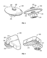
- FIG. 4 illustrates a top and bottom perspective view of an exemplary triangular-shaped mount.
- FIG. 5 illustrates a top and bottom perspective view of an exemplary elongated oval-shaped mount.
- FIG. 6 is a perspective view illustrating a triangular-shaped mount with a power optimizer.
- FIG. 7 illustrates a bottom perspective view a power optimizer being secured to a solar panel frame.
- FIG. 8 is an exploded top view of a disk/circular-shaped mount being used to secure a power optimizer to a solar panel frame.
- FIG. 9 is an exploded top view of both a triangular-shaped mount and an elongated oval-shaped mount being used to secure a power optimizer to a solar panel frame.
- FIGS. 10A and 10B illustrate perspective views of the various mounts and perspective views of an L-shaped bracket along with the elongated oval-shaped mount in combination with the L-shaped bracket.
- FIG. 11 illustrates a bottom perspective view of the L-shaped bracket secured to a solar panel frame with the elongated oval-shaped mount.
- FIG. 12 illustrates a bottom perspective view of the power optimizer secured between the L-shaped bracket and the elongated oval-shaped mount.
- FIG. 13 illustrates a cross-sectional view of the L-shaped bracket secured to the solar panel frame using the disk/circular-shaped mount.
- FIG. 14 illustrates a cross sectional view of FIG. 13 with the power optimizer installed between the L-shaped bracket and the disk/circular-shaped mount.
- FIG. 1 shows a typical electrical panel as an exemplary power optimizer 100 .
- a power optimizer conditions a solar panel's DC current output before sending it to a central inverter.
- the power optimizer 100 includes a cover 120 to shield the electronic components (not shown) inside the cover 120 .
- a series of cables 130 interconnect with the electronics inside the cover 120 .
- the electronic components and cover 120 are typically secured to a mounting bracket 110 .
- the mounting bracket 110 in this embodiment has an opening such as a guided slit 140 for receiving the threaded portion of a bolt.
- a typical solar panel array is secured to a roof 155 by securing each solar panel frame to a mounting rail 150 .
- FIG. 1 shows a typical electrical panel as an exemplary power optimizer 100 .
- a power optimizer conditions a solar panel's DC current output before sending it to a central inverter.
- the power optimizer 100 includes a cover 120 to shield the electronic components (not shown) inside the cover 120 .
- an exemplary micro-inverter 135 that includes cables 130 connected to the electronics in the micro inverter.
- a micro-inverter converts a solar panel's DC current to AC current.
- both the power optimizer 100 and the micro-inverter 135 are secured to the mounting rail 150 by way of a standard nut and bolt 160 through the guided slit 140 .
- the cables 130 can then be connected to the solar panel array.
- FIGS. 3-5 illustrate exemplary bracket mount assemblies for securing the power optimizers and micro-inverters to individual solar panel frames so that it is unnecessary to connect them to them to the mounting rails separately.
- FIG. 3 illustrates an exemplary disk or circular-shaped mount 200 .
- the mount 200 includes a rounded head flange 210 with a threaded aperture 225 through its middle for receiving a threaded shank 220 of a bolt 230 .
- the threaded aperture 225 typically extends from a top to a bottom surface of the flange 210 .
- the bolt 230 includes a serrated portion 240 that is both used to help secure the micro-inverter or power optimizer to a solar panel frame and penetrate a surface oxidation layer of the mounting bracket 110 of the micro inverter or power optimizer.
- the rounded head flange also includes a raised portion such as a circular tooth 250 on the bottom side of the flange that, when tightened, can penetrate the surface oxidation layer of a metal object such as the solar panel frame or other metal bracket.
- the mount 300 includes a triangular-shaped head flange 310 with a threaded aperture 320 through one end for receiving a threaded portion of a bolt 330 and includes a serrated portion 340 that is used to help secure the micro-invertor or power optimizer to the solar panel frame and penetrate the surface oxidation layer of the mounting bracket 110 of the micro-invertor or power optimizer.
- the arcs 315 on the bottom surface of the triangular-shaped head flange 310 are raised portions that, when tightened, can penetrate the surface oxidation layer of a metal object such as the solar panel frame or other metal bracket.
- the mount 400 includes an elongated oval-shaped head flange 410 with a threaded aperture 420 through one end of the flange 410 for receiving a bolt 430 and includes a serrated portion 440 that is used to help secure the micro-invertor or power optimizer to the solar panel frame and penetrate the surface oxidation layer of the mounting bracket 110 of the micro-invertor or power optimizer.
- the flange 410 also includes a raised portion such as the circular tooth 435 on the bottom side of the flange 410 on one end that, when tightened, is sufficiently sharp enough to penetrate the surface oxidation layer of a metal object such as the solar panel frame or other metal bracket.
- the flange 400 can also include a series of grips 450 on the end opposite the threaded aperture 420 to further assist in securing the mounting bracket 110 to the solar panel frame.
- All three mount embodiments can be installed by using the following two-step process.
- the triangular-shaped mount 300 is used to illustrate the installation process. First, the threaded shaft 220 of the triangular-shaped mount 300 slides through the opening such as the guided slit 140 of the mounting bracket 110 of the micro-invertor or power optimizer as shown below in FIG. 6 .
- the second step is to slide the mounting bracket 110 of the micro-invertor or power optimizer on to the lower lip 600 of the solar panel frame as shown below in FIG. 7 , and then tighten the mount 300 by turning the bolt 330 .
- the serrated portion 340 penetrates the surface oxidation layer of the bracket 110 and the arcs 315 penetrate the surface oxidation layer of the solar panel frame 600 .
- the serrated portion 240 will penetrate the surface oxidation layer of the mounting bracket 110 while the circular tooth 250 will penetrate the surface oxidation layer of the solar panel frame 600 .
- the serrated portion 440 will penetrate the surface oxidation layer of the mounting bracket 110 , while the circular tooth 435 will penetrate the surface oxidation layer of the solar panel frame 600 . In all these cases, an electrical connecting path is then created between the bracket and the solar panel frame.
- the circular mount 200 can be installed as shown in FIG. 8 by utilizing a non-orientation specific installation with the same steps provided above.
- the triangular and elongated oval-shaped mounts can be installed as shown in FIG. 9 by using an orientation-specific approach with the same steps as provided above.
- FIG. 10B illustrates an alternate exemplary embodiment that comprises the use of a third element, namely a support bracket 500 used in combination with each of the mounts 200 , 300 , or 400 .
- the support bracket 500 in this exemplary embodiment is an L-shaped support bracket and includes a perpendicular portion 520 and an open slot 510 that receives the bolts 230 , 330 , or 430 respectively in each of the mounts 200 , 300 , or 400 .
- the use of the bracket 500 can provide additional structural capability to the mounts 200 , 300 , or 400 and works on virtually any shape of solar panel frame.
- the mounts 200 , 300 , or 400 with the bracket 500 are installed in two steps.
- the first step involves assembling the mount 200 , 300 , or 400 on to the support bracket 500 as shown in FIG. 11 and then sliding the flange 210 , 310 , or 410 of the respective mount 200 , 300 , or 400 into place on the lip 600 of the solar panel frame as shown below in FIG. 11 .
- the perpendicular portion 520 of the bracket 500 can optionally rest against the solar panel frame as shown.
- the final step involves sliding the bracket 110 through the opening such as the guided slit 140 of the mounting bracket 110 of either the micro-inverter or the power optimizer into place on the support bracket 500 as shown in FIG. 12 and then tighten the mounts 200 , 300 , or 400 to the lower lip 600 of the solar panel frame by rotating the nut 230 , 330 , or 430 as shown.
- the support bracket 500 provides additional support to the bottom mounting bracket 110 and, fits most solar panel frame sizes.
- the serrated portion 240 , 340 , or 440 when tightened, will penetrate the surface oxidation layer of the mounting bracket 110 on the micro-inverter or the power optimizer, and the circular tooth 250 of the circular mount 200 , the tooth 435 of the elongated oval-shaped mount 400 , or the arcs 315 of the triangular-shaped mount 300 will penetrate the surface oxidation layer of the lip 600 of the solar panel frame and create an electrical connected path between the solar panel frame and the bracket 110 .
Abstract
Description
Claims (14)
Priority Applications (1)
| Application Number | Priority Date | Filing Date | Title |
|---|---|---|---|
| US15/610,403 US10312855B2 (en) | 2016-05-31 | 2017-05-31 | Bracket mount for securing micro-inverters and power optimizers to solar panel arrays |
Applications Claiming Priority (2)
| Application Number | Priority Date | Filing Date | Title |
|---|---|---|---|
| US201662343807P | 2016-05-31 | 2016-05-31 | |
| US15/610,403 US10312855B2 (en) | 2016-05-31 | 2017-05-31 | Bracket mount for securing micro-inverters and power optimizers to solar panel arrays |
Publications (2)
| Publication Number | Publication Date |
|---|---|
| US20170346441A1 US20170346441A1 (en) | 2017-11-30 |
| US10312855B2 true US10312855B2 (en) | 2019-06-04 |
Family
ID=60418492
Family Applications (1)
| Application Number | Title | Priority Date | Filing Date |
|---|---|---|---|
| US15/610,403 Active US10312855B2 (en) | 2016-05-31 | 2017-05-31 | Bracket mount for securing micro-inverters and power optimizers to solar panel arrays |
Country Status (1)
| Country | Link |
|---|---|
| US (1) | US10312855B2 (en) |
Cited By (11)
| Publication number | Priority date | Publication date | Assignee | Title |
|---|---|---|---|---|
| US20210359643A1 (en) * | 2017-11-13 | 2021-11-18 | Sunrun Inc. | Cable holder assemblies for a solar panel system |
| US11333179B2 (en) | 2011-12-29 | 2022-05-17 | Rmh Tech Llc | Mounting device for nail strip panels |
| US11512474B2 (en) | 2020-03-16 | 2022-11-29 | Rmh Tech Llc | Mounting device for a metal roof |
| US11573033B2 (en) | 2016-07-29 | 2023-02-07 | Rmh Tech Llc | Trapezoidal rib mounting bracket with flexible legs |
| US11608843B2 (en) * | 2017-08-15 | 2023-03-21 | Huawei Technologies Co., Ltd. | Photovoltaic module connection mechanical part |
| US11616468B2 (en) | 2018-03-21 | 2023-03-28 | Rmh Tech Llc | PV module mounting assembly with clamp/standoff arrangement |
| US11668332B2 (en) | 2018-12-14 | 2023-06-06 | Rmh Tech Llc | Mounting device for nail strip panels |
| US11774143B2 (en) | 2017-10-09 | 2023-10-03 | Rmh Tech Llc | Rail assembly with invertible side-mount adapter for direct and indirect mounting applications |
| US11788291B2 (en) | 2020-03-17 | 2023-10-17 | Rmh Tech Llc | Mounting device for controlling uplift of a metal roof |
| US11808043B2 (en) | 2016-10-31 | 2023-11-07 | Rmh Tech Llc | Metal panel electrical bonding clip |
| US11885139B2 (en) | 2011-02-25 | 2024-01-30 | Rmh Tech Llc | Mounting device for building surfaces having elongated mounting slot |
Families Citing this family (4)
| Publication number | Priority date | Publication date | Assignee | Title |
|---|---|---|---|---|
| PL3552307T3 (en) * | 2016-12-09 | 2023-08-28 | Ironridge, Inc. | Universal end clamp for securing solar panels to a rail support guide |
| USD862380S1 (en) * | 2017-07-27 | 2019-10-08 | Sungrow Power Supply Co., Ltd. | Power optimizer |
| CA3135545A1 (en) * | 2019-04-05 | 2020-10-08 | Primozone Production Ab | An ozone generator apparatus with fastening and grounding system |
| KR102033875B1 (en) * | 2019-05-07 | 2019-11-08 | 문상호 | Inverter installing structure for photovoltaic power generation apparatus |
Citations (18)
| Publication number | Priority date | Publication date | Assignee | Title |
|---|---|---|---|---|
| US20100147362A1 (en) | 2007-03-07 | 2010-06-17 | Greenrey, Inc. | Multi-function frame and integrated mounting system for photovoltaic power generating laminates |
| US20110008125A1 (en) * | 2009-07-13 | 2011-01-13 | United Technologies Corporation | Threaded flanged bushing for fastening applications |
| US8070404B1 (en) * | 2008-11-06 | 2011-12-06 | Middle Atlantic Products, Inc. | Bonding fastener assembly for electrical grounding |
| US20120274264A1 (en) * | 2011-04-26 | 2012-11-01 | Hyunrok Mun | Photovoltaic module |
| US20140072387A1 (en) * | 2012-09-10 | 2014-03-13 | Renewable Energy Holdings, Llc | Bonding Fastener with Environmental Seals |
| US8752338B2 (en) | 2012-05-04 | 2014-06-17 | D Three Enterprises, Llc | Adjustable roof mounting system |
| US20140202525A1 (en) | 2011-09-01 | 2014-07-24 | Sunedison, Llc | Solar module mounting bracket and assemblies |
| US20140263899A1 (en) | 2013-03-15 | 2014-09-18 | Unirac, Inc. | Apparatus for mounting a photovoltaic module |
| US8919053B2 (en) | 2009-07-02 | 2014-12-30 | Zep Solar, Llc | Leveling foot apparatus, system, and method for photovoltaic arrays |
| US20150023727A1 (en) * | 2013-07-16 | 2015-01-22 | Fasteners For Retail, Inc. | Lock for securing front rail to wire shelving |
| US20150129517A1 (en) | 2013-11-14 | 2015-05-14 | Ecolibrium Solar, Inc. | Modular Sloped Roof Solar Mounting System |
| US20150270802A1 (en) | 2014-01-29 | 2015-09-24 | D Three Enterprises, Llc | Adjustable combined flashing and mounting apparatus and method of mounting to be used therewith |
| US20160020726A1 (en) | 2013-03-28 | 2016-01-21 | Georgia Tech Research Corporation | Mounting Clips For Panel Installation |
| WO2016014042A1 (en) | 2014-07-22 | 2016-01-28 | Wencon Development, Inc. Dba Quick Mount Pv | Photovoltaic module accessory clamp |
| US20160036141A1 (en) * | 2014-07-31 | 2016-02-04 | Hubbell Incorporated | Electrical terminal |
| US20160111997A1 (en) | 2014-10-16 | 2016-04-21 | Unirac, Inc. | Apparatus for mounting photovoltaic modules |
| US20160268965A1 (en) * | 2015-03-10 | 2016-09-15 | Vermont Slate & Copper Services, Inc. | Mounting bracket assmebly |
| US9689411B2 (en) * | 2012-07-05 | 2017-06-27 | Ironridge, Inc. | Assembly for clamping and grounding objects |
-
2017
- 2017-05-31 US US15/610,403 patent/US10312855B2/en active Active
Patent Citations (22)
| Publication number | Priority date | Publication date | Assignee | Title |
|---|---|---|---|---|
| US20100147362A1 (en) | 2007-03-07 | 2010-06-17 | Greenrey, Inc. | Multi-function frame and integrated mounting system for photovoltaic power generating laminates |
| US8070404B1 (en) * | 2008-11-06 | 2011-12-06 | Middle Atlantic Products, Inc. | Bonding fastener assembly for electrical grounding |
| US8919053B2 (en) | 2009-07-02 | 2014-12-30 | Zep Solar, Llc | Leveling foot apparatus, system, and method for photovoltaic arrays |
| US8991114B2 (en) | 2009-07-02 | 2015-03-31 | Zep Solar, Llc | Pivot-fit connection apparatus, system, and method for photovoltaic modules |
| US20110008125A1 (en) * | 2009-07-13 | 2011-01-13 | United Technologies Corporation | Threaded flanged bushing for fastening applications |
| US20120274264A1 (en) * | 2011-04-26 | 2012-11-01 | Hyunrok Mun | Photovoltaic module |
| US20140202525A1 (en) | 2011-09-01 | 2014-07-24 | Sunedison, Llc | Solar module mounting bracket and assemblies |
| US8752338B2 (en) | 2012-05-04 | 2014-06-17 | D Three Enterprises, Llc | Adjustable roof mounting system |
| US20160118726A1 (en) | 2012-05-04 | 2016-04-28 | D Three Enterprises, Llc | Adjustable roof mounting system |
| US9106023B2 (en) | 2012-05-04 | 2015-08-11 | D Three Enterprises, Llc | Adjustable roof mounting system |
| US9689411B2 (en) * | 2012-07-05 | 2017-06-27 | Ironridge, Inc. | Assembly for clamping and grounding objects |
| US20140072387A1 (en) * | 2012-09-10 | 2014-03-13 | Renewable Energy Holdings, Llc | Bonding Fastener with Environmental Seals |
| US20140263899A1 (en) | 2013-03-15 | 2014-09-18 | Unirac, Inc. | Apparatus for mounting a photovoltaic module |
| US20160020726A1 (en) | 2013-03-28 | 2016-01-21 | Georgia Tech Research Corporation | Mounting Clips For Panel Installation |
| US20150023727A1 (en) * | 2013-07-16 | 2015-01-22 | Fasteners For Retail, Inc. | Lock for securing front rail to wire shelving |
| US20150129517A1 (en) | 2013-11-14 | 2015-05-14 | Ecolibrium Solar, Inc. | Modular Sloped Roof Solar Mounting System |
| US20150270802A1 (en) | 2014-01-29 | 2015-09-24 | D Three Enterprises, Llc | Adjustable combined flashing and mounting apparatus and method of mounting to be used therewith |
| WO2016014042A1 (en) | 2014-07-22 | 2016-01-28 | Wencon Development, Inc. Dba Quick Mount Pv | Photovoltaic module accessory clamp |
| US20170207743A1 (en) * | 2014-07-22 | 2017-07-20 | Wencon Development, Inc. Dba Quick Mount Pv | Photovoltaic module accessory clamp |
| US20160036141A1 (en) * | 2014-07-31 | 2016-02-04 | Hubbell Incorporated | Electrical terminal |
| US20160111997A1 (en) | 2014-10-16 | 2016-04-21 | Unirac, Inc. | Apparatus for mounting photovoltaic modules |
| US20160268965A1 (en) * | 2015-03-10 | 2016-09-15 | Vermont Slate & Copper Services, Inc. | Mounting bracket assmebly |
Cited By (14)
| Publication number | Priority date | Publication date | Assignee | Title |
|---|---|---|---|---|
| US11885139B2 (en) | 2011-02-25 | 2024-01-30 | Rmh Tech Llc | Mounting device for building surfaces having elongated mounting slot |
| US11333179B2 (en) | 2011-12-29 | 2022-05-17 | Rmh Tech Llc | Mounting device for nail strip panels |
| US11573033B2 (en) | 2016-07-29 | 2023-02-07 | Rmh Tech Llc | Trapezoidal rib mounting bracket with flexible legs |
| US11808043B2 (en) | 2016-10-31 | 2023-11-07 | Rmh Tech Llc | Metal panel electrical bonding clip |
| US11608843B2 (en) * | 2017-08-15 | 2023-03-21 | Huawei Technologies Co., Ltd. | Photovoltaic module connection mechanical part |
| US11774143B2 (en) | 2017-10-09 | 2023-10-03 | Rmh Tech Llc | Rail assembly with invertible side-mount adapter for direct and indirect mounting applications |
| US20210359643A1 (en) * | 2017-11-13 | 2021-11-18 | Sunrun Inc. | Cable holder assemblies for a solar panel system |
| US11848640B2 (en) * | 2017-11-13 | 2023-12-19 | Sunrun South Llc | Cable holder assemblies for a solar panel system |
| US11616468B2 (en) | 2018-03-21 | 2023-03-28 | Rmh Tech Llc | PV module mounting assembly with clamp/standoff arrangement |
| US11668332B2 (en) | 2018-12-14 | 2023-06-06 | Rmh Tech Llc | Mounting device for nail strip panels |
| US11739529B2 (en) | 2020-03-16 | 2023-08-29 | Rmh Tech Llc | Mounting device for a metal roof |
| US11512474B2 (en) | 2020-03-16 | 2022-11-29 | Rmh Tech Llc | Mounting device for a metal roof |
| US11965337B2 (en) | 2020-03-16 | 2024-04-23 | Rmh Tech Llc | Mounting device for a metal roof |
| US11788291B2 (en) | 2020-03-17 | 2023-10-17 | Rmh Tech Llc | Mounting device for controlling uplift of a metal roof |
Also Published As
| Publication number | Publication date |
|---|---|
| US20170346441A1 (en) | 2017-11-30 |
Similar Documents
| Publication | Publication Date | Title |
|---|---|---|
| US10312855B2 (en) | Bracket mount for securing micro-inverters and power optimizers to solar panel arrays | |
| US9671136B2 (en) | Clamp for securing and electrically bonding solar panels to a rail support | |
| US11601087B2 (en) | Apparatus for securing and covering a clamping device for solar panel modules | |
| US20170063300A1 (en) | Apparatus for Securing a Solar Panel Rail Guide to a Support Bracket | |
| AU2014329828C1 (en) | Mounting bracket assemblies and methods | |
| US9196978B2 (en) | Grounding and bonding bracket | |
| US8585000B2 (en) | Universal end clamp | |
| US10992251B2 (en) | Integrated bonding mid clamp device, system, and method for solar panel mounting and grounding | |
| US20160285408A1 (en) | Clamp for securing and electrically bonding solar panels to a rail support | |
| US20170170579A1 (en) | Bonding clamp | |
| US9865938B2 (en) | Apparatus for electrically bonding a solar array | |
| US11056998B2 (en) | Universal bonding end clamp | |
| US10224870B2 (en) | Bracket mounting assembly for securing junction boxes to solar panel arrays | |
| EP4178106A1 (en) | Universal end clamp for securing solar panels to a rail support guide | |
| US20170207743A1 (en) | Photovoltaic module accessory clamp | |
| US9528725B2 (en) | Solar panel frame clamps mounting a solar panel frame to a purlin | |
| US8672702B2 (en) | Electrical conductor arrangement as a component of a photovoltaic array | |
| JP6719108B2 (en) | Solar panel fixing device | |
| CN213425734U (en) | Quick self-locking strain clamp | |
| JPH09182263A (en) | Metal fitting for crossarm | |
| CN114556702A (en) | Mechanical grounding clamp |
Legal Events
| Date | Code | Title | Description |
|---|---|---|---|
| AS | Assignment |
Owner name: IRONRIDGE, INC., CALIFORNIA Free format text: ASSIGNMENT OF ASSIGNORS INTEREST;ASSIGNORS:LESTER, BRYAN, MR;PEREIRA, WILLIAM, MR;MEINE, SHAWN, MR.;SIGNING DATES FROM 20170527 TO 20170530;REEL/FRAME:042549/0875 |
|
| STPP | Information on status: patent application and granting procedure in general |
Free format text: RESPONSE TO NON-FINAL OFFICE ACTION ENTERED AND FORWARDED TO EXAMINER |
|
| STPP | Information on status: patent application and granting procedure in general |
Free format text: NOTICE OF ALLOWANCE MAILED -- APPLICATION RECEIVED IN OFFICE OF PUBLICATIONS |
|
| STPP | Information on status: patent application and granting procedure in general |
Free format text: PUBLICATIONS -- ISSUE FEE PAYMENT RECEIVED |
|
| STCF | Information on status: patent grant |
Free format text: PATENTED CASE |
|
| AS | Assignment |
Owner name: WILMINGTON TRUST, NATIONAL ASSOCIATION, DELAWARE Free format text: SECURITY INTEREST;ASSIGNORS:ECOFASTEN SOLAR, LLC;IRONRIDGE, INC.;PANELCLAW, INC.;AND OTHERS;REEL/FRAME:057365/0001 Effective date: 20210830 |
|
| MAFP | Maintenance fee payment |
Free format text: PAYMENT OF MAINTENANCE FEE, 4TH YR, SMALL ENTITY (ORIGINAL EVENT CODE: M2551); ENTITY STATUS OF PATENT OWNER: SMALL ENTITY Year of fee payment: 4 |
|
| FEPP | Fee payment procedure |
Free format text: ENTITY STATUS SET TO UNDISCOUNTED (ORIGINAL EVENT CODE: BIG.); ENTITY STATUS OF PATENT OWNER: LARGE ENTITY |