US806387A - Dumping-wagon. - Google Patents
Dumping-wagon. Download PDFInfo
- Publication number
- US806387A US806387A US23931405A US1905239314A US806387A US 806387 A US806387 A US 806387A US 23931405 A US23931405 A US 23931405A US 1905239314 A US1905239314 A US 1905239314A US 806387 A US806387 A US 806387A
- Authority
- US
- United States
- Prior art keywords
- dog
- ratchet
- pawl
- lever
- winch
- Prior art date
- Legal status (The legal status is an assumption and is not a legal conclusion. Google has not performed a legal analysis and makes no representation as to the accuracy of the status listed.)
- Expired - Lifetime
Links
- 238000010276 construction Methods 0.000 description 1
Images
Classifications
-
- B—PERFORMING OPERATIONS; TRANSPORTING
- B05—SPRAYING OR ATOMISING IN GENERAL; APPLYING FLUENT MATERIALS TO SURFACES, IN GENERAL
- B05D—PROCESSES FOR APPLYING FLUENT MATERIALS TO SURFACES, IN GENERAL
- B05D3/00—Pretreatment of surfaces to which liquids or other fluent materials are to be applied; After-treatment of applied coatings, e.g. intermediate treating of an applied coating preparatory to subsequent applications of liquids or other fluent materials
- B05D3/02—Pretreatment of surfaces to which liquids or other fluent materials are to be applied; After-treatment of applied coatings, e.g. intermediate treating of an applied coating preparatory to subsequent applications of liquids or other fluent materials by baking
- B05D3/0218—Pretreatment, e.g. heating the substrate
- B05D3/0245—Pretreatment, e.g. heating the substrate with induction heating
Definitions
- This invention relates tofthe class of dumpdirection, while a dog engages the ratchet to prevent reverse movementof the ratchet when 7 released from the-pawl.
- I v I i he object of the invention is toprovide simple, durable, and efiicient means for throw- I ing the dog and pawl both out of engagement in with the ratchet by the samelever'whichcarries theaforesaid pawl, thus requiring only one lever for operating the winchto lift the .floor to its closed position and for releasing the winch to allow the said floor to drop toits open position; and to that end the invention consists in the novel construction and combination of the winch operating and controlling de vices hereinafter described, andias illustrated in the accompanying drawings, in which;
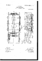
- Figure 1 is a side view of the body of a dumping-wagon embodying my invention in" its normal condition.
- Fig. 2 is a plan view of the same.
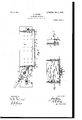
- I Fig. 3 is a longitudinal section on the line 3 3' in Fig. 2.
- Fig. 4 is filiIfiJlSr verse section on the line 4 4 in Fig. '1.
- Fig. 5 is an enlarged vertical transverse section of the winch operating and controlling devices.
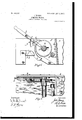
- Fig. 6 is a plan view of the'same'.
- Fig.7 is
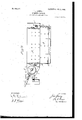
- Fig. 8 is a vertical longitudinal section of the body-of a dumpingfwagon, showing my invention in position for dropping the .floor' ofsaid body. Similar letters of reference indicatecorre- .sponding parts.
- dumping- Wflgonp i Y B denotes the drop new or bottomfof, said I body, which floor is'divided intotwo side sec-f tionshinged tothebody, as shown at aim, to
- brackets 0 0, to'which v are pivoted sheaves (Z d, on the under sides of which run chains e (2, each of which. passes over'a horizontalroller f, mounted in. bear-. lngsf f, attached to the exterior of the rear end of thebody A;
- the rear end portions of. said chains pass from the roller f down to. the ends of the bars-.65 and are fastened thereto.
- the front end portionsof the chains pass from the front sheaves d d upandover aroller g, pivotally supported on-the exterior Thechains of the frontend of the. body A.
- a lever Lis pivotally connected to the 'winch'and has pivoted to it a.
- pawl a which engages-jthe ratchet when the lever L isoperated to wind the chains 66 on the winch, and
- j represents the dog which engages the" of while thepawl is carriedto'a position to ratchet to prevent retrograde movement there-' obtain a new hold on they ratchet.
- This dog the said dog to normally engage the ratchet, I form the dog'with a depending weight Z,
- What I claim asmy invention is 1.
Landscapes
- Portable Nailing Machines And Staplers (AREA)
Description
No. 806,887. PATENTED' DEC. 5, 1905 A J.Y0UNG.I DUMPING WAGON.
' 4 SHEETS-SHEET 1;
H I U N u f 1 MI mil 'f i an?! Lfi w 7 l a gag; F m; u f I iii 1 I WITNESSES: v 17w a EJTTORNEY.
'No. 806,387. 'PATBNTED 13136.5,1905.
J. YOUNG.
DUMPING' WAGON.
APPLICATION FILED JAN. 3. 1905.
4 SHEETS-SHEET 2.
mmmsze: I v 4 INVENT I flrflTTORA IY.
No. 806,387. PATENTED DEC. 5, 1905.
1 J. YOUNG.
DUMPING WAGON.
'APPLICATION FILED JAN- 3, 1905.
4 SHEETS-SHEET 3.
11v VEJVTOR ,4 ATTORNEY.
No-806,387. PATENTBD DEC. 5, 190
' 'J. YOUNG;
DUMPING WAGON.
APPLICATION FILED JAN. 3. 1905.
' 4 SHEETS-SHEET 4.
Jay 1d WITNESSES v C I INVENTOR:
To all whom it may concern/.-
*JQHN'VYOUNG, on SYRACUSE, NEW YORK.
' pommwe wneou. l
Specification of Letters Patent.
Patented Dec. 5, 1905.
Application filed January 3, 1905. Serial no. 239,314. I
' Be itknown that '1, JOHN YOUNG, of Syracuse, in the county of'Onondaga, in the State ofNew York, have invented new and useful Improvements in Dumping-Wagons, of which the following, taken in connection with the. accompanying drawings, is a full, clear, and.
exact description.
This invention relates tofthe class of dumpdirection, while a dog engages the ratchet to prevent reverse movementof the ratchet when 7 released from the-pawl. I v I i he object of the invention is toprovide simple, durable, and efiicient means for throw- I ing the dog and pawl both out of engagement in with the ratchet by the samelever'whichcarries theaforesaid pawl, thus requiring only one lever for operating the winchto lift the .floor to its closed position and for releasing the winch to allow the said floor to drop toits open position; and to that end the invention consists in the novel construction and combination of the winch operating and controlling de vices hereinafter described, andias illustrated in the accompanying drawings, in which;
Figure 1 is a side view of the body of a dumping-wagon embodying my invention in" its normal condition. Fig. 2 is a plan view of the same. I Fig. 3 is a longitudinal section on the line 3 3' in Fig. 2. Fig. 4 is filiIfiJlSr verse section on the line 4 4 in Fig. '1. Fig. 5 is an enlarged vertical transverse section of the winch operating and controlling devices.
' Fig. 6 is a plan view of the'same'. Fig.7 is
a transverse section on the line 7 7 111 Fig.5; and Fig; 8 isa vertical longitudinal section of the body-of a dumpingfwagon, showing my invention in position for dropping the .floor' ofsaid body. Similar letters of reference indicatecorre- .sponding parts. I
* represents the body of the. dumping- Wflgonp i Y B denotes the drop new or bottomfof, said I body, which floor is'divided intotwo side sec-f tionshinged tothebody, as shown at aim, to
allow said sections to drop .into position to d scharge'the contents of the body.
Tothe under side of the floor-sections, ad
ja'cent to the meeting edges thereof, areattachedlongitudinal bars 6 b, which serve to stiffen said sections. To the end portions of these bars are attached brackets 0 0, to'which v are pivoted sheaves (Z d, on the under sides of which run chains e (2, each of which. passes over'a horizontalroller f, mounted in. bear-. lngsf f, attached to the exterior of the rear end of thebody A; The rear end portions of. said chainspass from the roller f down to. the ends of the bars-.65 and are fastened thereto. The front end portionsof the chains pass from the front sheaves d d upandover aroller g, pivotally supported on-the exterior Thechains of the frontend of the. body A. V passthence to the winch C, upon which they 'arewound. Said winch is mounted in suitable bearings'attached to extensions A of the sidewallsof the body A. it represents a ratchet which isfastenedto the winch. I
A lever Lis pivotally connected to the 'winch'and has pivoted to it a. pawl a, which engages-jthe ratchet when the lever L isoperated to wind the chains 66 on the winch, and
thereby lift the floor-sections to close the bottom of the body A.
j represents the dog which engages the" of while thepawl is carriedto'a position to ratchet to prevent retrograde movement there-' obtain a new hold on they ratchet. This dog the said dog to normally engage the ratchet, I form the dog'with a depending weight Z,
"is pivoted to a bracket R. attached to the side d of the body extension A. In order to cause I, 9
which is disposed to swing the dog jinto en- I gagement with the ratchet. In order to throwthe saiddog and pawl out ofengagement by the same lever Lwhich carries said pawl, I form the dog with an upwardly-extending armn andwith a head oonthe top of the frontv of the dog and attach to the lever L a V stud or roller 9, which is caused to press on theback of the free end of the .arm n by a I downward pressure applied to the lever. Said pressure on the arm n throws the dog j out of engagement with the ratchet. I Simultanes ously'with this movement of the dog the head othereof engages the under side of the pawl c' and lifts the same from thefratchet. -T he ratchet being thus released from the dog j and pawl allows the winch C to-yield to the v strain of the chains 6 e,which are thus unwound on the winch and caused to allow the floorseotions B to drop to their open position .on the body A, as shown in Fig, 8 of the drawings.
In lifting the floor-sections to their closed position the lever is swung rearward from the position shown in Figs. 1, '2, and 5 of the drawings, and in this movement therarm n and head 0 of the dog jare out of engagement with the stud or roller 7 and pawl 71, and thus the said dog is allowed to assume itsnormal position for engaging the ratchet and prevent retrograde movement of the ratchet while released from the pawlz; in swinging the lever L forward to cause the pawl to. obtain a new hold on the ratchet-..
To carry the chains 6 e laterally from under the center of the body A and shield said chains. when the floor-sections are dropped to discharge the contents of the said body, I attach to the under side of said floor-sectionssu'itable brackets 25 2 disposedat intervals in the. length of the body A and-receiving the chains through them.
What I claim asmy inventionis 1. The combination, with the ratchet, lever and pawl pivotedtosaid lever, 'ofa dogdis-H posed to become interposed between the pawl and ratchet by the movement of the lever and actuated-by said lever to throw dog from the ratchet and simultaneously cause the dog to pry the pawloutof. engagement as set forth.
2.. The combination with the ratchet, lever and pawl pivoted to said lever, of a pivoted dog disposed to become i'ntrpased between tivelythelever and the pawl and therebythrow the dog and pawl both out of engagement by, the movement of the lever in one. direction.-
4. The combination, with the wagon-body havingdrop-floorsectionshinged to said body, a floor-lifting winch,'a ratchet attached to said winch, and a lever provided with a pawl for engaging the ratchet, of a dogformed with 9. depending weight to hold the dog normally in engagement withthe ratchet, a forwardlyprojecting head on the dog and an upwardlyextending arm fixed tothe dog and disposed in front thereof, and a roller pivoted to the handle and in position to pressthe aforesaid arm forward and thereby throw the dog out of engagement and cause the head thereof to hold the pawl from engagement asset forth.
JOHN: YOUNG. Witnesses:
L. .H. FULMER,. J. J. LAAss.
Priority Applications (1)
| Application Number | Priority Date | Filing Date | Title |
|---|---|---|---|
| US23931405A US806387A (en) | 1905-01-03 | 1905-01-03 | Dumping-wagon. |
Applications Claiming Priority (1)
| Application Number | Priority Date | Filing Date | Title |
|---|---|---|---|
| US23931405A US806387A (en) | 1905-01-03 | 1905-01-03 | Dumping-wagon. |
Publications (1)
| Publication Number | Publication Date |
|---|---|
| US806387A true US806387A (en) | 1905-12-05 |
Family
ID=2874870
Family Applications (1)
| Application Number | Title | Priority Date | Filing Date |
|---|---|---|---|
| US23931405A Expired - Lifetime US806387A (en) | 1905-01-03 | 1905-01-03 | Dumping-wagon. |
Country Status (1)
| Country | Link |
|---|---|
| US (1) | US806387A (en) |
-
1905
- 1905-01-03 US US23931405A patent/US806387A/en not_active Expired - Lifetime
Similar Documents
| Publication | Publication Date | Title |
|---|---|---|
| US806387A (en) | Dumping-wagon. | |
| US718742A (en) | Coke-oven lorry. | |
| US1034061A (en) | Elevator-way. | |
| US350855A (en) | edwin woodward | |
| US998432A (en) | Dump-car. | |
| US56518A (en) | Improved dumping-car | |
| US377519A (en) | Stock-loading chute | |
| US218999A (en) | Improvement in dumping-wagons | |
| US1037226A (en) | Rail-loader. | |
| US867726A (en) | Dumping-car. | |
| US492090A (en) | Wag o n-body | |
| US871771A (en) | Dump-wagon. | |
| US785310A (en) | Dumping wagon-rack. | |
| US983110A (en) | Car-dumping mechanism. | |
| US260269A (en) | Dumping-wagon | |
| US855267A (en) | Dumping device for vehicles. | |
| US698338A (en) | Apparatus for lifting wagon-boxes, & c. | |
| US842807A (en) | Apparatus for unloading platform-cars. | |
| US502278A (en) | Dumping-wagon | |
| US402895A (en) | Hay-stacker | |
| US685425A (en) | Railroad-track cleaner or flanger. | |
| US808973A (en) | Dumping-wagon. | |
| US898533A (en) | Dumping-wagon. | |
| US475565A (en) | Dumping apparatus | |
| US1003010A (en) | Hay-rack. |