US8057179B1 - Film cooling hole for turbine airfoil - Google Patents
Film cooling hole for turbine airfoil Download PDFInfo
- Publication number
- US8057179B1 US8057179B1 US12/252,513 US25251308A US8057179B1 US 8057179 B1 US8057179 B1 US 8057179B1 US 25251308 A US25251308 A US 25251308A US 8057179 B1 US8057179 B1 US 8057179B1
- Authority
- US
- United States
- Prior art keywords
- film cooling
- expansion
- cooling hole
- film
- airfoil
- Prior art date
- Legal status (The legal status is an assumption and is not a legal conclusion. Google has not performed a legal analysis and makes no representation as to the accuracy of the status listed.)
- Expired - Fee Related, expires
Links
Images


Classifications
-
- F—MECHANICAL ENGINEERING; LIGHTING; HEATING; WEAPONS; BLASTING
- F01—MACHINES OR ENGINES IN GENERAL; ENGINE PLANTS IN GENERAL; STEAM ENGINES
- F01D—NON-POSITIVE DISPLACEMENT MACHINES OR ENGINES, e.g. STEAM TURBINES
- F01D5/00—Blades; Blade-carrying members; Heating, heat-insulating, cooling or antivibration means on the blades or the members
- F01D5/12—Blades
- F01D5/14—Form or construction
- F01D5/18—Hollow blades, i.e. blades with cooling or heating channels or cavities; Heating, heat-insulating or cooling means on blades
- F01D5/186—Film cooling
-
- F—MECHANICAL ENGINEERING; LIGHTING; HEATING; WEAPONS; BLASTING
- F05—INDEXING SCHEMES RELATING TO ENGINES OR PUMPS IN VARIOUS SUBCLASSES OF CLASSES F01-F04
- F05D—INDEXING SCHEME FOR ASPECTS RELATING TO NON-POSITIVE-DISPLACEMENT MACHINES OR ENGINES, GAS-TURBINES OR JET-PROPULSION PLANTS
- F05D2250/00—Geometry
- F05D2250/20—Three-dimensional
- F05D2250/29—Three-dimensional machined; miscellaneous
- F05D2250/292—Three-dimensional machined; miscellaneous tapered
-
- F—MECHANICAL ENGINEERING; LIGHTING; HEATING; WEAPONS; BLASTING
- F05—INDEXING SCHEMES RELATING TO ENGINES OR PUMPS IN VARIOUS SUBCLASSES OF CLASSES F01-F04
- F05D—INDEXING SCHEME FOR ASPECTS RELATING TO NON-POSITIVE-DISPLACEMENT MACHINES OR ENGINES, GAS-TURBINES OR JET-PROPULSION PLANTS
- F05D2260/00—Function
- F05D2260/20—Heat transfer, e.g. cooling
- F05D2260/202—Heat transfer, e.g. cooling by film cooling
-
- F—MECHANICAL ENGINEERING; LIGHTING; HEATING; WEAPONS; BLASTING
- F05—INDEXING SCHEMES RELATING TO ENGINES OR PUMPS IN VARIOUS SUBCLASSES OF CLASSES F01-F04
- F05D—INDEXING SCHEME FOR ASPECTS RELATING TO NON-POSITIVE-DISPLACEMENT MACHINES OR ENGINES, GAS-TURBINES OR JET-PROPULSION PLANTS
- F05D2260/00—Function
- F05D2260/20—Heat transfer, e.g. cooling
- F05D2260/221—Improvement of heat transfer
Definitions
- the present invention relates generally to a gas turbine engine, and more specifically to a film cooling hole for a turbine airfoil.
- Airfoils used in a gas turbine engine such as rotor blades and stator vanes (guide nozzles), require film cooling of the external surface where the hottest gas flow temperatures are found.
- the airfoil leading edge region is exposed to the highest gas flow temperature and therefore film cooling holes are used here.
- Film cooling holes discharge pressurized cooling, air onto the airfoil surface as a layer that forms a blanket to protect the metal surface from the hot gas flow.
- the prior art is full of complex film hole shapes that are designed to maximize the film coverage on the airfoil surface while minimizing loses.
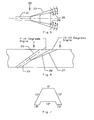
- FIGS. 1 and 2 show a prior art film cooling hole with a large length to diameter (L/D) ratio as discloses in U.S. Pat. No. 6,869,268 B2 issued to Liang on Mar. 22, 2005 and entitled COMBUSTION TURBINE WITH AIRFOIL HAVING ENHANCED LEADING EDGE DIFFUSION HOLES AND RELATED METHODS.
- the straight circular showerhead hole in FIG. 1 has to be at around 14 degrees relative to the airfoil leading edge surface. This also results in a length to diameter ration of near 14. Both the film cooling hole angle and L/D exceed current manufacturing capability.
- FIG. 2 shows a one dimension diffusion showerhead film cooling hole design which reduces the shallow angle required by the straight hole and changes the associated L/D ratio to a more producible level.
- This film cooling hole includes a constant diameter section at the entrance region of the hole that provides cooling flow metering capability, and a one dimension diffusion section with less than 10 degrees expansion in the airfoil radial inboard direction. As a result of this design, a large film cooling hole breakout is achieved and the airfoil leading edge film cooling coverage and film effectiveness level is increased over the FIG. 1 straight film cooling hole.
- a two dimensional compound shaped film hole as well as a two dimensional shaped film cooling hole with curved expansion is utilized to enhance film coverage and to minimize the radial over-expansion when these cooling holes are used in conjunction with a compound angle.
- U.S. Pat. No. 4,653,983 issued to Vehr on Mar. 31, 1987 and entitled CROSS-FLOW FILM COOLING PASSAGE and U.S. Pat. No. 5,382,133 issued to Moore et al on Jan. 7, 1995 and entitled HIGH COVERAGE SHAPED DIFFUSER FILM HOLE FOR THIN WALLS both disclose this type of film cooling hole.
- FIG. 3 shows a regular shaped film cooling hole of the prior art with the film ejection stream 11 located above the airfoil surface 12 in which vortices 13 form underneath the film cooling discharge from the hole.
- the film cooling hole is the standard 10-10-10 expansion file hole where the two sides and the bottom of downstream side of the hole all have 10 degrees of expansion.
- the film flow will penetrate into the main stream and then reattach to the airfoil surface at a distance of around 2 times the film hole diameter.
- hot gas injection into the space below the film injection location and subsequently a pair of vortices is formed under the film flow.
- the film effectiveness is reduced.
- the film layer of cooling air reattaches to the airfoil surface downstream from the vortices that are formed.
- the film cooling hole of the present invention includes a constant diameter metering section followed by a divergent section downstream that includes multiple divergent sidewalls.
- the two side walls of the film hole have around 10 degrees expansion.
- the downstream side wall of the film hole has a middle surface with an expansion of around 7-10 degrees and an expansion of from 10-15 degrees on the two corners of this surface. There is no expansion for the film hole on the upstream sidewall where the film cooling hole is in contact with the hot gas flow. The multiple expansions occur on the downstream side wall surface only.
- FIG. 1 shows a cross section view of a prior art film cooling hole with an expansion on the downstream side wall surface.
- FIG. 2 shows a cross section view of a prior art film cooling hole with a straight hole passing through the wall.
- FIG. 3 shows a side view of the film cooling flow from the hole and over the airfoil surface of the prior art film cooling holes.
- FIG. 4 shows a side view of the film cooling flow over the airfoil surface for the film cooling hole of the present invention.
- FIG. 5 shows a cross section view from the top surface of the film cooling hole of the present invention.
- FIG. 6 shows a cross section side view of the film cooling hole of the present invention.
- FIG. 7 shows a front view of the opening surface of the film cooling hole of the present invention.
- the film cooling hole of the present invention is disclosed for use in a turbine airfoil, such as a rotor blade or a stator vane, in order to provide film cooling for the airfoil surface.
- the film cooling hole can also be used for film cooling of other turbine parts such as the combustor liner, or other parts that require film cooling for protection against a hot gas flow over the surface outside of the gas turbine engine field.
- FIGS. 5-7 show the film cooling hole of the present invention is various views.
- FIG. 5 shows a cross section view from the upstream side wall surface or top where the film cooling hole 20 includes a constant diameter inlet section that functions as a metering section for the film hole and a diffusion section 22 downstream that opens onto the airfoil surface.
- the film hole 20 includes an upstream side wall with no expansion, and two side walls 28 and 29 that both have a 10 degree expansion.
- the downstream side wall includes a middle surface with an expansion of 7-10 degrees and two corners that have an expansion greater than the middle section of 10-15 degrees expansion.
- the downstream side wall has two corners with an expansion greater than the expansion of the middle section so that the film flow occurs as seen in FIG. 4 .
- the film cooling hole 20 of the present invention includes a constant diameter inlet section to provide cooling flow metering, and is followed by a multiple expansion at the diffusion section downstream from the metering inlet section.
- the upstream side wall produces no expansion where the film cooling hole is in contact with the hot gas flow.
- a single diffusion is still used for both the two side walls.
- the multiple expansions occur on the downstream side wall surface only.
- the multiple expansion surfaces is defined as 10 to 15 degrees downstream on both the corners and 7 to 10 degree expansion in the middle portion.
- the multiple expansion at both corners for the downstream expansion surface is extended further out than the middle portion of the downstream expansion surface to force the ejected film flow to move toward the two corners.
- This movement toward the corners acts to minimize the formation of vortices under the film stream at the injection location.
- Higher film effectiveness is generated by minimizing film layer shear mixing with the hot gas flow vortices and film cooling air. An improved film layer can then be established on the airfoil surface which will yield a higher film effectiveness level over the cited prior art references.
Landscapes
- Engineering & Computer Science (AREA)
- Mechanical Engineering (AREA)
- General Engineering & Computer Science (AREA)
- Turbine Rotor Nozzle Sealing (AREA)
Abstract
Description
Claims (12)
Priority Applications (1)
| Application Number | Priority Date | Filing Date | Title |
|---|---|---|---|
| US12/252,513 US8057179B1 (en) | 2008-10-16 | 2008-10-16 | Film cooling hole for turbine airfoil |
Applications Claiming Priority (1)
| Application Number | Priority Date | Filing Date | Title |
|---|---|---|---|
| US12/252,513 US8057179B1 (en) | 2008-10-16 | 2008-10-16 | Film cooling hole for turbine airfoil |
Publications (1)
| Publication Number | Publication Date |
|---|---|
| US8057179B1 true US8057179B1 (en) | 2011-11-15 |
Family
ID=44906843
Family Applications (1)
| Application Number | Title | Priority Date | Filing Date |
|---|---|---|---|
| US12/252,513 Expired - Fee Related US8057179B1 (en) | 2008-10-16 | 2008-10-16 | Film cooling hole for turbine airfoil |
Country Status (1)
| Country | Link |
|---|---|
| US (1) | US8057179B1 (en) |
Cited By (24)
| Publication number | Priority date | Publication date | Assignee | Title |
|---|---|---|---|---|
| US20100329846A1 (en) * | 2009-06-24 | 2010-12-30 | Honeywell International Inc. | Turbine engine components |
| US20110123312A1 (en) * | 2009-11-25 | 2011-05-26 | Honeywell International Inc. | Gas turbine engine components with improved film cooling |
| US20110293423A1 (en) * | 2010-05-28 | 2011-12-01 | General Electric Company | Articles which include chevron film cooling holes, and related processes |
| US20130115103A1 (en) * | 2011-11-09 | 2013-05-09 | General Electric Company | Film hole trench |
| US8628293B2 (en) | 2010-06-17 | 2014-01-14 | Honeywell International Inc. | Gas turbine engine components with cooling hole trenches |
| EP2861909A2 (en) * | 2012-06-13 | 2015-04-22 | General Electric Company | Gas turbine engine wall |
| US20160090843A1 (en) * | 2014-09-30 | 2016-03-31 | General Electric Company | Turbine components with stepped apertures |
| US9650900B2 (en) | 2012-05-07 | 2017-05-16 | Honeywell International Inc. | Gas turbine engine components with film cooling holes having cylindrical to multi-lobe configurations |
| US9976746B2 (en) | 2015-09-02 | 2018-05-22 | General Electric Company | Combustor assembly for a turbine engine |
| US10024169B2 (en) | 2015-02-27 | 2018-07-17 | General Electric Company | Engine component |
| US10113433B2 (en) | 2012-10-04 | 2018-10-30 | Honeywell International Inc. | Gas turbine engine components with lateral and forward sweep film cooling holes |
| US10132166B2 (en) | 2015-02-27 | 2018-11-20 | General Electric Company | Engine component |
| US10168051B2 (en) | 2015-09-02 | 2019-01-01 | General Electric Company | Combustor assembly for a turbine engine |
| US10197278B2 (en) | 2015-09-02 | 2019-02-05 | General Electric Company | Combustor assembly for a turbine engine |
| US10309239B2 (en) | 2013-02-15 | 2019-06-04 | United Technologies Corporation | Cooling hole for a gas turbine engine component |
| US10392947B2 (en) | 2015-07-13 | 2019-08-27 | General Electric Company | Compositions and methods of attachment of thick environmental barrier coatings on CMC components |
| US10563867B2 (en) | 2015-09-30 | 2020-02-18 | General Electric Company | CMC articles having small complex features for advanced film cooling |
| US10704424B2 (en) | 2013-11-04 | 2020-07-07 | Raytheon Technologies Corporation | Coated cooling passage |
| US11021965B2 (en) | 2016-05-19 | 2021-06-01 | Honeywell International Inc. | Engine components with cooling holes having tailored metering and diffuser portions |
| CN113027537A (en) * | 2021-03-11 | 2021-06-25 | 河北工业大学 | Air film hole structure and turbine blade |
| US11149646B2 (en) | 2015-09-02 | 2021-10-19 | General Electric Company | Piston ring assembly for a turbine engine |
| US11352888B2 (en) * | 2018-08-10 | 2022-06-07 | Ningbo Institute Of Materials Technology & Engineering, Chinese Academy Of Sciences | Turbine blade having gas film cooling structure with a composite irregular groove and a method of manufacturing the same |
| US11402097B2 (en) | 2018-01-03 | 2022-08-02 | General Electric Company | Combustor assembly for a turbine engine |
| US20220412219A1 (en) * | 2015-11-11 | 2022-12-29 | General Electric Company | Component for a gas turbine engine with a film hole |
Citations (8)
| Publication number | Priority date | Publication date | Assignee | Title |
|---|---|---|---|---|
| US4653983A (en) | 1985-12-23 | 1987-03-31 | United Technologies Corporation | Cross-flow film cooling passages |
| US4664597A (en) * | 1985-12-23 | 1987-05-12 | United Technologies Corporation | Coolant passages with full coverage film cooling slot |
| US4684323A (en) | 1985-12-23 | 1987-08-04 | United Technologies Corporation | Film cooling passages with curved corners |
| US5382133A (en) | 1993-10-15 | 1995-01-17 | United Technologies Corporation | High coverage shaped diffuser film hole for thin walls |
| US6183199B1 (en) | 1998-03-23 | 2001-02-06 | Abb Research Ltd. | Cooling-air bore |
| US6287075B1 (en) * | 1997-10-22 | 2001-09-11 | General Electric Company | Spanwise fan diffusion hole airfoil |
| US6869268B2 (en) | 2002-09-05 | 2005-03-22 | Siemens Westinghouse Power Corporation | Combustion turbine with airfoil having enhanced leading edge diffusion holes and related methods |
| US6918742B2 (en) | 2002-09-05 | 2005-07-19 | Siemens Westinghouse Power Corporation | Combustion turbine with airfoil having multi-section diffusion cooling holes and methods of making same |
-
2008
- 2008-10-16 US US12/252,513 patent/US8057179B1/en not_active Expired - Fee Related
Patent Citations (8)
| Publication number | Priority date | Publication date | Assignee | Title |
|---|---|---|---|---|
| US4653983A (en) | 1985-12-23 | 1987-03-31 | United Technologies Corporation | Cross-flow film cooling passages |
| US4664597A (en) * | 1985-12-23 | 1987-05-12 | United Technologies Corporation | Coolant passages with full coverage film cooling slot |
| US4684323A (en) | 1985-12-23 | 1987-08-04 | United Technologies Corporation | Film cooling passages with curved corners |
| US5382133A (en) | 1993-10-15 | 1995-01-17 | United Technologies Corporation | High coverage shaped diffuser film hole for thin walls |
| US6287075B1 (en) * | 1997-10-22 | 2001-09-11 | General Electric Company | Spanwise fan diffusion hole airfoil |
| US6183199B1 (en) | 1998-03-23 | 2001-02-06 | Abb Research Ltd. | Cooling-air bore |
| US6869268B2 (en) | 2002-09-05 | 2005-03-22 | Siemens Westinghouse Power Corporation | Combustion turbine with airfoil having enhanced leading edge diffusion holes and related methods |
| US6918742B2 (en) | 2002-09-05 | 2005-07-19 | Siemens Westinghouse Power Corporation | Combustion turbine with airfoil having multi-section diffusion cooling holes and methods of making same |
Cited By (34)
| Publication number | Priority date | Publication date | Assignee | Title |
|---|---|---|---|---|
| US8371814B2 (en) | 2009-06-24 | 2013-02-12 | Honeywell International Inc. | Turbine engine components |
| US20100329846A1 (en) * | 2009-06-24 | 2010-12-30 | Honeywell International Inc. | Turbine engine components |
| US20110123312A1 (en) * | 2009-11-25 | 2011-05-26 | Honeywell International Inc. | Gas turbine engine components with improved film cooling |
| US8529193B2 (en) | 2009-11-25 | 2013-09-10 | Honeywell International Inc. | Gas turbine engine components with improved film cooling |
| US8905713B2 (en) * | 2010-05-28 | 2014-12-09 | General Electric Company | Articles which include chevron film cooling holes, and related processes |
| US20110293423A1 (en) * | 2010-05-28 | 2011-12-01 | General Electric Company | Articles which include chevron film cooling holes, and related processes |
| US8628293B2 (en) | 2010-06-17 | 2014-01-14 | Honeywell International Inc. | Gas turbine engine components with cooling hole trenches |
| US8858175B2 (en) * | 2011-11-09 | 2014-10-14 | General Electric Company | Film hole trench |
| US20130115103A1 (en) * | 2011-11-09 | 2013-05-09 | General Electric Company | Film hole trench |
| US9650900B2 (en) | 2012-05-07 | 2017-05-16 | Honeywell International Inc. | Gas turbine engine components with film cooling holes having cylindrical to multi-lobe configurations |
| EP2861909A2 (en) * | 2012-06-13 | 2015-04-22 | General Electric Company | Gas turbine engine wall |
| US20150159871A1 (en) * | 2012-06-13 | 2015-06-11 | General Electric Company | Gas turbine engine wall |
| US10386069B2 (en) * | 2012-06-13 | 2019-08-20 | General Electric Company | Gas turbine engine wall |
| US10113433B2 (en) | 2012-10-04 | 2018-10-30 | Honeywell International Inc. | Gas turbine engine components with lateral and forward sweep film cooling holes |
| US10822971B2 (en) | 2013-02-15 | 2020-11-03 | Raytheon Technologies Corporation | Cooling hole for a gas turbine engine component |
| US10309239B2 (en) | 2013-02-15 | 2019-06-04 | United Technologies Corporation | Cooling hole for a gas turbine engine component |
| US10704424B2 (en) | 2013-11-04 | 2020-07-07 | Raytheon Technologies Corporation | Coated cooling passage |
| US20160090843A1 (en) * | 2014-09-30 | 2016-03-31 | General Electric Company | Turbine components with stepped apertures |
| US10132166B2 (en) | 2015-02-27 | 2018-11-20 | General Electric Company | Engine component |
| US10024169B2 (en) | 2015-02-27 | 2018-07-17 | General Electric Company | Engine component |
| US10392947B2 (en) | 2015-07-13 | 2019-08-27 | General Electric Company | Compositions and methods of attachment of thick environmental barrier coatings on CMC components |
| US10197278B2 (en) | 2015-09-02 | 2019-02-05 | General Electric Company | Combustor assembly for a turbine engine |
| US9976746B2 (en) | 2015-09-02 | 2018-05-22 | General Electric Company | Combustor assembly for a turbine engine |
| US11898494B2 (en) | 2015-09-02 | 2024-02-13 | General Electric Company | Piston ring assembly for a turbine engine |
| US10168051B2 (en) | 2015-09-02 | 2019-01-01 | General Electric Company | Combustor assembly for a turbine engine |
| US11149646B2 (en) | 2015-09-02 | 2021-10-19 | General Electric Company | Piston ring assembly for a turbine engine |
| US10563867B2 (en) | 2015-09-30 | 2020-02-18 | General Electric Company | CMC articles having small complex features for advanced film cooling |
| US20220412219A1 (en) * | 2015-11-11 | 2022-12-29 | General Electric Company | Component for a gas turbine engine with a film hole |
| US11773729B2 (en) * | 2015-11-11 | 2023-10-03 | General Electric Company | Component for a gas turbine engine with a film hole |
| US11286791B2 (en) | 2016-05-19 | 2022-03-29 | Honeywell International Inc. | Engine components with cooling holes having tailored metering and diffuser portions |
| US11021965B2 (en) | 2016-05-19 | 2021-06-01 | Honeywell International Inc. | Engine components with cooling holes having tailored metering and diffuser portions |
| US11402097B2 (en) | 2018-01-03 | 2022-08-02 | General Electric Company | Combustor assembly for a turbine engine |
| US11352888B2 (en) * | 2018-08-10 | 2022-06-07 | Ningbo Institute Of Materials Technology & Engineering, Chinese Academy Of Sciences | Turbine blade having gas film cooling structure with a composite irregular groove and a method of manufacturing the same |
| CN113027537A (en) * | 2021-03-11 | 2021-06-25 | 河北工业大学 | Air film hole structure and turbine blade |
Similar Documents
| Publication | Publication Date | Title |
|---|---|---|
| US8057179B1 (en) | Film cooling hole for turbine airfoil | |
| US8057180B1 (en) | Shaped film cooling hole for turbine airfoil | |
| US8057181B1 (en) | Multiple expansion film cooling hole for turbine airfoil | |
| US8066484B1 (en) | Film cooling hole for a turbine airfoil | |
| US8690538B2 (en) | Leading edge cooling using chevron trip strips | |
| US7494319B1 (en) | Turbine blade tip configuration | |
| EP1870561B1 (en) | Leading edge cooling of a gas turbine component using staggered turbulator strips | |
| US8961136B1 (en) | Turbine airfoil with film cooling hole | |
| EP1645722B1 (en) | Turbine airfoil with stepped coolant outlet slots | |
| US7997868B1 (en) | Film cooling hole for turbine airfoil | |
| US8246307B2 (en) | Blade for a rotor | |
| US9145773B2 (en) | Asymmetrically shaped trailing edge cooling holes | |
| US9175569B2 (en) | Turbine airfoil trailing edge cooling slots | |
| US8435004B1 (en) | Turbine blade with tip rail cooling | |
| US20090304499A1 (en) | Counter-Vortex film cooling hole design | |
| US20030021684A1 (en) | Turbine blade tip cooling construction | |
| US6612808B2 (en) | Article wall with interrupted ribbed heat transfer surface | |
| US20140023497A1 (en) | Cooled turbine blade tip shroud with film/purge holes | |
| US8061989B1 (en) | Turbine blade with near wall cooling | |
| EP2792851B1 (en) | Turbine blade | |
| US9017026B2 (en) | Turbine airfoil trailing edge cooling slots | |
| US8591191B1 (en) | Film cooling hole for turbine airfoil | |
| US8568097B1 (en) | Turbine blade with core print-out hole | |
| US7798776B1 (en) | Turbine blade with showerhead film cooling | |
| KR20150063949A (en) | Turbine blade with near wall microcircuit edge cooling |
Legal Events
| Date | Code | Title | Description |
|---|---|---|---|
| STCF | Information on status: patent grant |
Free format text: PATENTED CASE |
|
| AS | Assignment |
Owner name: FLORIDA TURBINE TECHNOLOGIES, INC., FLORIDA Free format text: ASSIGNMENT OF ASSIGNORS INTEREST;ASSIGNOR:LIANG, GEORGE;REEL/FRAME:027289/0497 Effective date: 20111031 |
|
| FPAY | Fee payment |
Year of fee payment: 4 |
|
| SULP | Surcharge for late payment | ||
| AS | Assignment |
Owner name: SUNTRUST BANK, GEORGIA Free format text: SUPPLEMENT NO. 1 TO AMENDED AND RESTATED INTELLECTUAL PROPERTY SECURITY AGREEMENT;ASSIGNORS:KTT CORE, INC.;FTT AMERICA, LLC;TURBINE EXPORT, INC.;AND OTHERS;REEL/FRAME:048521/0081 Effective date: 20190301 |
|
| FEPP | Fee payment procedure |
Free format text: MAINTENANCE FEE REMINDER MAILED (ORIGINAL EVENT CODE: REM.); ENTITY STATUS OF PATENT OWNER: SMALL ENTITY |
|
| LAPS | Lapse for failure to pay maintenance fees |
Free format text: PATENT EXPIRED FOR FAILURE TO PAY MAINTENANCE FEES (ORIGINAL EVENT CODE: EXP.); ENTITY STATUS OF PATENT OWNER: SMALL ENTITY |
|
| STCH | Information on status: patent discontinuation |
Free format text: PATENT EXPIRED DUE TO NONPAYMENT OF MAINTENANCE FEES UNDER 37 CFR 1.362 |
|
| FP | Lapsed due to failure to pay maintenance fee |
Effective date: 20191115 |
|
| AS | Assignment |
Owner name: FLORIDA TURBINE TECHNOLOGIES, INC., FLORIDA Free format text: RELEASE BY SECURED PARTY;ASSIGNOR:TRUIST BANK (AS SUCCESSOR BY MERGER TO SUNTRUST BANK), COLLATERAL AGENT;REEL/FRAME:059619/0336 Effective date: 20220330 Owner name: CONSOLIDATED TURBINE SPECIALISTS, LLC, OKLAHOMA Free format text: RELEASE BY SECURED PARTY;ASSIGNOR:TRUIST BANK (AS SUCCESSOR BY MERGER TO SUNTRUST BANK), COLLATERAL AGENT;REEL/FRAME:059619/0336 Effective date: 20220330 Owner name: FTT AMERICA, LLC, FLORIDA Free format text: RELEASE BY SECURED PARTY;ASSIGNOR:TRUIST BANK (AS SUCCESSOR BY MERGER TO SUNTRUST BANK), COLLATERAL AGENT;REEL/FRAME:059619/0336 Effective date: 20220330 Owner name: KTT CORE, INC., FLORIDA Free format text: RELEASE BY SECURED PARTY;ASSIGNOR:TRUIST BANK (AS SUCCESSOR BY MERGER TO SUNTRUST BANK), COLLATERAL AGENT;REEL/FRAME:059619/0336 Effective date: 20220330 |