US8042629B2 - Snow traction unit for vehicles - Google Patents
Snow traction unit for vehicles Download PDFInfo
- Publication number
- US8042629B2 US8042629B2 US12/303,743 US30374307A US8042629B2 US 8042629 B2 US8042629 B2 US 8042629B2 US 30374307 A US30374307 A US 30374307A US 8042629 B2 US8042629 B2 US 8042629B2
- Authority
- US
- United States
- Prior art keywords
- track
- snow
- vehicle
- guide rail
- carrier wheels
- Prior art date
- Legal status (The legal status is an assumption and is not a legal conclusion. Google has not performed a legal analysis and makes no representation as to the accuracy of the status listed.)
- Expired - Fee Related, expires
Links
Images


Classifications
-
- B—PERFORMING OPERATIONS; TRANSPORTING
- B62—LAND VEHICLES FOR TRAVELLING OTHERWISE THAN ON RAILS
- B62D—MOTOR VEHICLES; TRAILERS
- B62D55/00—Endless track vehicles
- B62D55/04—Endless track vehicles with tracks and alternative ground wheels, e.g. changeable from endless track vehicle into wheeled vehicle and vice versa
-
- B—PERFORMING OPERATIONS; TRANSPORTING
- B62—LAND VEHICLES FOR TRAVELLING OTHERWISE THAN ON RAILS
- B62D—MOTOR VEHICLES; TRAILERS
- B62D55/00—Endless track vehicles
- B62D55/06—Endless track vehicles with tracks without ground wheels
- B62D55/065—Multi-track vehicles, i.e. more than two tracks
-
- B—PERFORMING OPERATIONS; TRANSPORTING
- B62—LAND VEHICLES FOR TRAVELLING OTHERWISE THAN ON RAILS
- B62D—MOTOR VEHICLES; TRAILERS
- B62D55/00—Endless track vehicles
- B62D55/08—Endless track units; Parts thereof
- B62D55/084—Endless-track units or carriages mounted separably, adjustably or extensibly on vehicles, e.g. portable track units
-
- B—PERFORMING OPERATIONS; TRANSPORTING
- B62—LAND VEHICLES FOR TRAVELLING OTHERWISE THAN ON RAILS
- B62D—MOTOR VEHICLES; TRAILERS
- B62D55/00—Endless track vehicles
- B62D55/08—Endless track units; Parts thereof
- B62D55/10—Bogies; Frames
-
- B—PERFORMING OPERATIONS; TRANSPORTING
- B62—LAND VEHICLES FOR TRAVELLING OTHERWISE THAN ON RAILS
- B62D—MOTOR VEHICLES; TRAILERS
- B62D55/00—Endless track vehicles
- B62D55/08—Endless track units; Parts thereof
- B62D55/12—Arrangement, location, or adaptation of driving sprockets
- B62D55/125—Final drives
-
- B—PERFORMING OPERATIONS; TRANSPORTING
- B62—LAND VEHICLES FOR TRAVELLING OTHERWISE THAN ON RAILS
- B62D—MOTOR VEHICLES; TRAILERS
- B62D55/00—Endless track vehicles
- B62D55/08—Endless track units; Parts thereof
- B62D55/18—Tracks
- B62D55/20—Tracks of articulated type, e.g. chains
Definitions
- This invention relates to the conversion of vehicle particularly 4 wheel drive vehicles to over snow vehicles with improved snow handling.
- U.S. Pat. No. 3,710,886 discloses a conversion kit with a track for each side of a vehicle and the use of the brakes for steering. The track passes over a series of rollers.
- U.S. Pat. No. 4,069,883 discloses a street car conversion with front skis for steering and a rear track for propulsion.
- U.S. Pat. No. 4,313,516 discloses a similar arrangement which uses a chain drive from the rear wheels for the track.
- the tracks use rollers to support the track belt.
- U.S. Pat. No. 4,719,882 is also a ski and track combination and takes its power from an extended drive shaft.
- U.S. Pat. No. 5,855,248 discloses a kit that uses the existing wheels but is more for soft ground rather than snow.
- U.S. Pat. No. 5,388,656 discloses a track for the road wheel of a tractor.
- U.S. Pat. No. 5,343,960 discloses a tracked conversion for a tractor that also uses an hydraulic steering attachment that is steered from the steering wheel. A single track is used on each side and the tracks pass over a horizontal slide when contacting the snow.
- U.S. Pat. No. 5,361,860 discloses a track conversion where the steering is from attached trailing equipment.
- U.S. Pat. No. 5,924,503 discloses a drive system for a tracked wheel.
- U.S. Pat. No. 6,199,646 discloses a semi-crawler arrangement for the rear wheel of a farm tractor.
- the present invention provides a vehicle snow conversion unit which replaces a wheel of a wheeled vehicle said unit comprising drive engagement means which is engagable with the vehicle drive shaft an endless belt which is driven by the drive engagement means, which belt passes over horizontal plate to provide a bearing surface on the snow.
- the advantage of this invention is that a separate unit is used with each wheel and by appropriate sizing of the width and the length of the track, the force imprint is less than 250 Kg/square meter.
- the present invention provides a snow traction unit to replace a wheel of an all wheel drive vehicle which includes
- This invention is in part predicated on the realization that where the track passes over a series of rollers the weight of the vehicle is born on a series of line contacts corresponding to the roller positions and this results in very high force imprints onto the snow.
- the provision of the plate support for the track eliminates this problem.
- 4 wheel drive vehicles can be converted to over snow vehicles with a force imprint of less than 250 Kg/square meter.
- the track that fits over each wheel incorporates a ski section over which the track moves.
- Each unit preferably consists of two track support wheels over which the snow contact track passes. These two wheels are spaced apart to provide a horizontal track section between the lower extremity of each wheel and a flat surface is provided for the track to pass over.
- This flat plate is coated in a low friction material such as, polyethylene.
- Each unit has a frame that supports the two track carrier wheels and the track support plate.
- a drive pulley is driven by the vehicle axle and a belt from the drive pulley to at least one of the carrier wheels, provides the means to move the endless track over the support plate. Snow lubricates the surfaces between the moving track and the stationary polyethylene coated plate.
- the endless belt preferably moves over the surface of an endless rail and is held to the rail by slidable bracket that enclose the rail and ensures that the belt cannot become detached from the guide rail.
- the endless rail functions as the support plate between the wheels. Rubber sprockets or pneumatic tires with a sprocket surface are used as the wheels to engage, guide and drive the endless belt.
- the guide rail preferably extends around the periphery of the sprockets and preferably the sprockets incorporate a recess to accommodate the rail so that the sprocket rotates past the stationary rail.
- the tracks include a central portion that passes over the plate and at least one lateral track portion spaced from the central track by spacer spars. This results in the track being flexible in two directions both longitudinally and laterally.
- the front pair of tracks are steerable from the vehicle steering mechanism and optionally the rear tracks may be included, to provide an all wheel steering mechanism.
- each track unit is preferably below the units centre of mass and preferably below 300 mm above the snow surface.
- the drag link in the steering mechanism for each pair of front and rear units incorporates an hydraulic actuator that is attached to the track unit at a point behind the pivot points of the front track units and in front of the pivot points of the rear track units. The hydraulic actuator for the rear wheels moves opposite to the direction of the front actuator.
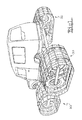
- FIG. 1 shows a vehicle mounted on a snow traction unit according to one embodiment of this invention
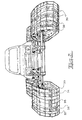
- FIG. 2 is a front view showing the snow contact tracks of one embodiment of this invention.
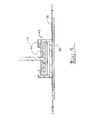
- FIG. 3 is a side view of one of the track assemblies shown in FIGS. 1 and 2 ;
- FIG. 4 is a detailed schematic view of FIG. 3 ;
- FIG. 5 is a cross sectional view of the track and guide rail
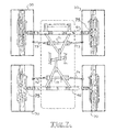
- FIG. 6 is a schematic outline of the steering system according the embodiment illustrated in FIG. 1 ;
- FIG. 7 is a schematic of the steering mechanism of FIG. 6 .
- the embodiment illustrated consists of a chassis 11 onto which a vehicle 13 , preferably a four wheel drive vehicle, is placed, so that the front and rear axles 15 , 16 align with the 4 snow track units 30 which are attached to the chassis 11 .
- a vehicle 13 preferably a four wheel drive vehicle
- Each snow track unit 30 has a snow contact track surface 32 composed of 5 separate belts 33 , 34 , 35 36 and 37 linked by the lateral battens 38 .
- These battens 38 may be made of spring steel and are secured to tracks 34 and 36 by brackets 39 and are elastically attached to the other tracks.
- the width of the track units, which is preferably about a meter and the lateral flexibility provided by the battens 38 provide a better snow contact surface that is able to flex longitudinally and laterally. This lateral flexibility provided by the battens 38 enables the track units 30 to respond to varying surface topology.
- the central track 35 is an endless belt that moves over a support rail 40 .
- the central track 35 also moves over the track engaging wheels 53 and 54 which function as sprockets.
- the wheels 53 and 54 may be solid rubber or pneumatic tyres and this provides added resilience and flexibility to the track units in traversing uneven ground.
- the support rail 40 is accommodated in a central groove of the outer surface of the wheels 53 and 54 .
- the central track 35 is attached to the rail 40 by slidable brackets 43 that encompass the rail 40 as shown in FIG. 5 . This ensures that the track 35 cannot detach from the rail 40 during use.
- the rail 40 is composed of a spring steel plate 44 coated in low friction polyethylene 45 which has a low frictional contact with the track 35 and this contact surface is lubricated by snow entering between the lower surface of rail 40 and the internal surface of the track 35 .
- Cogs 42 on the wheels 53 and 54 are located on either side of the rail 40 and engage with the brackets 43 of track 35 so that the brackets 43 pass along on either side of the rail 40 .
- the wheels 53 and 54 are supported by the bar 46 which is part of the track unit support frame.
- the flexible transverse spars 38 provide a cushioning effect which allows much faster movement over rocky terrain than any prior art system. Vehicles fitted with the units of this invention can move up riverbeds at about fifteen Kmh. This is faster than tanks can move in such terrain.
- a pneumatic tire may be provided around the entire central belt 35 such that vehicles would be able to move very fast over rocky terrain. It would also eliminate the only high pressure point (line) on the unit and would thus allow movement over minefields with non-magnetic triggers.
- Each snow track unit 30 has a drive pulley 52 driven by the vehicle axle associated with that unit.
- the drive pulley 52 rotates the belt 51 to drive wheel 53 .
- the drive belt 51 is tensioned by roller 56 .
- a quick release attachment means such a ball and socket attachment for attaching the individual track units 30 to a four wheel drive vehicle can be provided.
- pivot point for each unit 30 is below the drive shaft and as close to the ground surface as is feasible.
- the vehicle steering mechanism is replaced with a hydraulic system responsive to the steering wheel and which turns the front pair of snow track units in one direction and the rear pair in the alternate direction to provide 4 wheel steering of the vehicle as illustrated in FIG. 6 .
- This avoids the use of differential braking as a means of steering the vehicle and minimizes shear on the snow to provide maximum traction on the snow surface.
- the main elements of the steering mechanism are two hydraulic actuators 71 located behind the front drive shaft 61 and 72 located in front of the rear drive shaft 62 . These form the drag link for the steering mechanism with the radius arms 73 and 74 attaching to the units 30 in the same plane as the pivot points 75 of the units 30 relative to the chassis.
- the radius arms in this embodiment are arranged so that the inside track has a maximum angle of deflection of 18° and the outer wheel 11°.
- the hydraulic actuator 71 moves in the opposite direction to actuator 72 so that the units move as in a 4 wheel steering vehicle as depicted schematically in FIG. 6 . However it is also possible to decouple the actuators 71 , 72 so that each can be operated independently if the conditions warrant it.
- the units are able to individually pivot in the longitudinal direction which means the units can oscillate in a longitudinal direction such that the tip and tail can move up and down. This is not possible with prior art tracks use rigidly mounted tracks. This allows the vehicles fitted with the units of this invention to traverse very difficult terrain and climb steps.
- the present invention provides a unique and low cost conversion of a four wheel drive road vehicle to a snow vehicle.
Landscapes
- Engineering & Computer Science (AREA)
- Chemical & Material Sciences (AREA)
- Combustion & Propulsion (AREA)
- Transportation (AREA)
- Mechanical Engineering (AREA)
- Non-Deflectable Wheels, Steering Of Trailers, Or Other Steering (AREA)
- Cleaning Of Streets, Tracks, Or Beaches (AREA)
- Motorcycle And Bicycle Frame (AREA)
- Handcart (AREA)
- Escalators And Moving Walkways (AREA)
- Steering-Linkage Mechanisms And Four-Wheel Steering (AREA)
- Platform Screen Doors And Railroad Systems (AREA)
Abstract
A snow traction unit to replace a wheel of an all wheel drive vehicle which includes a frame supporting two carrier wheels; said carrier wheels being spaced apart a distance greater than their combined radii; an endless snow contacting track mounted for rotation on said carrier wheels; a track contacting surface provided between the lower extremities of said carrier wheels; a drive engagement means for engaging the drive shaft of the vehicle and for driving at least one of said carrier wheels; the arrangement of the width of the track, the spacing between the carrier wheels and the track contacting surface resulting in the vehicle having a force imprint less than 250 Kg/square meter.
Description
This application is a National Phase filing under 35 U.S.C. §371 of PCT/AU2007/000804 filed Jun. 8, 2007, which claims priority to Patent Application No. 2006903108, filed in Australia on Jun. 8, 2006. The entire contents of each of the above-applications are incorporated herein by reference.
This invention relates to the conversion of vehicle particularly 4 wheel drive vehicles to over snow vehicles with improved snow handling.
Many over snow vehicles can only be used for that purpose. There is a need for conversion units that can convert wheeled vehicles to effective over snow vehicles.
U.S. Pat. No. 3,710,886 discloses a conversion kit with a track for each side of a vehicle and the use of the brakes for steering. The track passes over a series of rollers.
U.S. Pat. No. 4,069,883 discloses a street car conversion with front skis for steering and a rear track for propulsion.
U.S. Pat. No. 4,313,516 discloses a similar arrangement which uses a chain drive from the rear wheels for the track. The tracks use rollers to support the track belt.
U.S. Pat. No. 4,719,882 is also a ski and track combination and takes its power from an extended drive shaft.
U.S. Pat. No. 5,855,248 discloses a kit that uses the existing wheels but is more for soft ground rather than snow.
Some patents have been concerned with farm tractor conversions.
U.S. Pat. No. 5,388,656 discloses a track for the road wheel of a tractor. U.S. Pat. No. 5,343,960 discloses a tracked conversion for a tractor that also uses an hydraulic steering attachment that is steered from the steering wheel. A single track is used on each side and the tracks pass over a horizontal slide when contacting the snow.
U.S. Pat. No. 5,361,860 discloses a track conversion where the steering is from attached trailing equipment.
U.S. Pat. No. 5,924,503 discloses a drive system for a tracked wheel.
U.S. Pat. No. 6,199,646 discloses a semi-crawler arrangement for the rear wheel of a farm tractor.
These prior art arrangements are generally unsatisfactory because the vehicle load on the snow is too high and the steering of the vehicle is non responsive or places the snow under too much shear so that propulsion over snow is inhibited. Eg: two directional shear when traversing, transverse, across a slope, one track moving faster than the other to prevent sideways slip, the effect being a torque onto the snow. All existing oversnow vehicles have a side slope maximum traverse angle of about thirteen degrees.
It is an object of this invention to provide a conversion for vehicles that ameliorates these problems
To this end the present invention provides a vehicle snow conversion unit which replaces a wheel of a wheeled vehicle said unit comprising drive engagement means which is engagable with the vehicle drive shaft an endless belt which is driven by the drive engagement means, which belt passes over horizontal plate to provide a bearing surface on the snow.
The advantage of this invention is that a separate unit is used with each wheel and by appropriate sizing of the width and the length of the track, the force imprint is less than 250 Kg/square meter.
Thus in one aspect the present invention provides a snow traction unit to replace a wheel of an all wheel drive vehicle which includes
-
- a) a frame supporting two carrier wheels
- b) said carrier wheels being spaced apart a distance greater than their combined radii
- c) an endless snow contacting track mounted for rotation on said carrier wheels
- d) a track contacting surface provided between the lower extremities of said carrier wheels
- e) a drive engagement means for engaging the drive shaft of the vehicle and for driving at least one of said carrier wheels
the arrangement of the width of the track, the spacing between the carrier wheels and the track contacting surface resulting in the vehicle having a force imprint less than 250 Kg/square meter.
This invention is in part predicated on the realization that where the track passes over a series of rollers the weight of the vehicle is born on a series of line contacts corresponding to the roller positions and this results in very high force imprints onto the snow. The provision of the plate support for the track eliminates this problem.
4 wheel drive vehicles can be converted to over snow vehicles with a force imprint of less than 250 Kg/square meter. The track that fits over each wheel incorporates a ski section over which the track moves.
Each unit preferably consists of two track support wheels over which the snow contact track passes. These two wheels are spaced apart to provide a horizontal track section between the lower extremity of each wheel and a flat surface is provided for the track to pass over. This flat plate is coated in a low friction material such as, polyethylene. Each unit has a frame that supports the two track carrier wheels and the track support plate. In one embodiment a drive pulley is driven by the vehicle axle and a belt from the drive pulley to at least one of the carrier wheels, provides the means to move the endless track over the support plate. Snow lubricates the surfaces between the moving track and the stationary polyethylene coated plate. The endless belt preferably moves over the surface of an endless rail and is held to the rail by slidable bracket that enclose the rail and ensures that the belt cannot become detached from the guide rail. The endless rail functions as the support plate between the wheels. Rubber sprockets or pneumatic tires with a sprocket surface are used as the wheels to engage, guide and drive the endless belt. The guide rail preferably extends around the periphery of the sprockets and preferably the sprockets incorporate a recess to accommodate the rail so that the sprocket rotates past the stationary rail.
The tracks include a central portion that passes over the plate and at least one lateral track portion spaced from the central track by spacer spars. This results in the track being flexible in two directions both longitudinally and laterally.
The front pair of tracks are steerable from the vehicle steering mechanism and optionally the rear tracks may be included, to provide an all wheel steering mechanism.
Steering does not rely on changing the relative speed of tracks on opposite sides of the vehicle (as in steering by braking) but by using a steering system adapted with a hydraulic system. It is preferred to provide 4 wheel steering by using the hydraulic assisted steering to move the rear wheels opposite to the front wheels. The pivot point, relative to the chassis, of each track unit is preferably below the units centre of mass and preferably below 300 mm above the snow surface. The drag link in the steering mechanism for each pair of front and rear units incorporates an hydraulic actuator that is attached to the track unit at a point behind the pivot points of the front track units and in front of the pivot points of the rear track units. The hydraulic actuator for the rear wheels moves opposite to the direction of the front actuator. It is within the scope of this invention to provide for decoupling of the hydraulic actuators so that the front and rear wheels can be steered independently using a separate control lever for each actuator. This enables the vehicle to traverse difficult terrain or obstacles and to move diagonally relative to the centre line of the vehicle chassis.
A preferred embodiment of the invention is shown in the illustrations in which
The embodiment illustrated consists of a chassis 11 onto which a vehicle 13, preferably a four wheel drive vehicle, is placed, so that the front and rear axles 15, 16 align with the 4 snow track units 30 which are attached to the chassis 11.
Each snow track unit 30 has a snow contact track surface 32 composed of 5 separate belts 33, 34, 35 36 and 37 linked by the lateral battens 38. These battens 38 may be made of spring steel and are secured to tracks 34 and 36 by brackets 39 and are elastically attached to the other tracks. The width of the track units, which is preferably about a meter and the lateral flexibility provided by the battens 38 provide a better snow contact surface that is able to flex longitudinally and laterally. This lateral flexibility provided by the battens 38 enables the track units 30 to respond to varying surface topology.
The central track 35 is an endless belt that moves over a support rail 40. The central track 35 also moves over the track engaging wheels 53 and 54 which function as sprockets. The wheels 53 and 54 may be solid rubber or pneumatic tyres and this provides added resilience and flexibility to the track units in traversing uneven ground. The support rail 40 is accommodated in a central groove of the outer surface of the wheels 53 and 54. The central track 35 is attached to the rail 40 by slidable brackets 43 that encompass the rail 40 as shown in FIG. 5 . This ensures that the track 35 cannot detach from the rail 40 during use.
The rail 40 is composed of a spring steel plate 44 coated in low friction polyethylene 45 which has a low frictional contact with the track 35 and this contact surface is lubricated by snow entering between the lower surface of rail 40 and the internal surface of the track 35. Cogs 42 on the wheels 53 and 54 are located on either side of the rail 40 and engage with the brackets 43 of track 35 so that the brackets 43 pass along on either side of the rail 40. The wheels 53 and 54 are supported by the bar 46 which is part of the track unit support frame. The flexible transverse spars 38 provide a cushioning effect which allows much faster movement over rocky terrain than any prior art system. Vehicles fitted with the units of this invention can move up riverbeds at about fifteen Kmh. This is faster than tanks can move in such terrain. If desired a pneumatic tire may be provided around the entire central belt 35 such that vehicles would be able to move very fast over rocky terrain. It would also eliminate the only high pressure point (line) on the unit and would thus allow movement over minefields with non-magnetic triggers.
Each snow track unit 30 has a drive pulley 52 driven by the vehicle axle associated with that unit. The drive pulley 52 rotates the belt 51 to drive wheel 53. The drive belt 51 is tensioned by roller 56.
A quick release attachment means such a ball and socket attachment for attaching the individual track units 30 to a four wheel drive vehicle can be provided.
It is preferred that the pivot point for each unit 30 is below the drive shaft and as close to the ground surface as is feasible.
The vehicle steering mechanism is replaced with a hydraulic system responsive to the steering wheel and which turns the front pair of snow track units in one direction and the rear pair in the alternate direction to provide 4 wheel steering of the vehicle as illustrated in FIG. 6 . This avoids the use of differential braking as a means of steering the vehicle and minimizes shear on the snow to provide maximum traction on the snow surface.
As shown in FIG. 7 the main elements of the steering mechanism are two hydraulic actuators 71 located behind the front drive shaft 61 and 72 located in front of the rear drive shaft 62. These form the drag link for the steering mechanism with the radius arms 73 and 74 attaching to the units 30 in the same plane as the pivot points 75 of the units 30 relative to the chassis. The radius arms in this embodiment are arranged so that the inside track has a maximum angle of deflection of 18° and the outer wheel 11°. The hydraulic actuator 71 moves in the opposite direction to actuator 72 so that the units move as in a 4 wheel steering vehicle as depicted schematically in FIG. 6 . However it is also possible to decouple the actuators 71, 72 so that each can be operated independently if the conditions warrant it.
The units are able to individually pivot in the longitudinal direction which means the units can oscillate in a longitudinal direction such that the tip and tail can move up and down. This is not possible with prior art tracks use rigidly mounted tracks. This allows the vehicles fitted with the units of this invention to traverse very difficult terrain and climb steps.
It is within the scope of this invention to have a hydraulicly controlled gear change mechanism on each unit, to allow high speed movement on flat terrain.
It can be seen from the above description that the present invention provides a unique and low cost conversion of a four wheel drive road vehicle to a snow vehicle.
Those skilled in the art will realize that other embodiments using different components may be made without departing from the core teachings of this invention.
Claims (6)
1. A snow traction unit to replace a wheel of a vehicle, wherein said snow traction unit includes:
a) a frame supporting two carrier wheels;
b) said carrier wheels being spaced apart a distance greater than their combined radii;
c) an endless snow contacting track mounted for rotation en around said carrier wheels; and
d) a guide rail provided between the lower extremities of said carrier wheels, wherein said snow contacting track moves over said guide rail;
e) a drive engagement means engaging a drive shaft of the vehicle and driving at least one of said carrier wheels, wherein the guide rail includes a contact surface of a low friction material and during operation, snow enters between and lubricates the endless track and the guide rail, and wherein the endless track is coupled to the guide rail by slidable brackets that encompass the guide rail so as to prevent detachment of the endless track from the guide rail during use,
the arrangement of the width of the track, the spacing between the carrier wheels and the guide rail resulting in the vehicle having a force imprint less than 250 Kg/square meter.
2. The snow traction unit as claimed in claim 1 in which the carrier wheels are composed of rubber or incorporate a pneumatic tire.
3. The snow traction unit as claimed in claim 1 in which the belt includes a central portion that passes over the guide rail and at least one lateral portion spaced from the central portion by spacer bars so that the belt is flexible in two directions both longitudinally and laterally.
4. A four wheel drive vehicle in which each of the four wheels is replaced by a snow traction unit as claimed in claim 1 in which the front pair of units are steerable by a first hydraulic actuator.
5. The vehicle as claimed in claim 4 , wherein the rear pair snow traction units are steered by a second hydraulic actuator and in which the two hydraulic actuators are coupled so that the rear actuator moves in the opposite direction to the front actuator.
6. A vehicle as claimed in claim 5 in which a drag link of the front steering actuator is connected to one of the front units behind respective pivot points of the two front traction units and a drag link of the rear wheel steering actuator is connected to one of the rear units in front of respective pivot points of the two rear traction units.
Applications Claiming Priority (3)
| Application Number | Priority Date | Filing Date | Title |
|---|---|---|---|
| AU2006903108A AU2006903108A0 (en) | 2006-06-08 | Snow Traction Unit for Vehicles | |
| AU2006903108 | 2006-06-08 | ||
| PCT/AU2007/000804 WO2007140539A1 (en) | 2006-06-08 | 2007-06-08 | Snow traction unit for vehicles |
Publications (2)
| Publication Number | Publication Date |
|---|---|
| US20100219004A1 US20100219004A1 (en) | 2010-09-02 |
| US8042629B2 true US8042629B2 (en) | 2011-10-25 |
Family
ID=38800974
Family Applications (1)
| Application Number | Title | Priority Date | Filing Date |
|---|---|---|---|
| US12/303,743 Expired - Fee Related US8042629B2 (en) | 2006-06-08 | 2007-06-08 | Snow traction unit for vehicles |
Country Status (11)
| Country | Link |
|---|---|
| US (1) | US8042629B2 (en) |
| EP (1) | EP2024223B1 (en) |
| CN (1) | CN101472784B (en) |
| AT (1) | ATE502839T1 (en) |
| AU (1) | AU2007257339B2 (en) |
| CA (1) | CA2654015C (en) |
| DE (1) | DE602007013392D1 (en) |
| NZ (1) | NZ573046A (en) |
| PL (1) | PL2024223T3 (en) |
| RU (1) | RU2433933C2 (en) |
| WO (1) | WO2007140539A1 (en) |
Cited By (4)
| Publication number | Priority date | Publication date | Assignee | Title |
|---|---|---|---|---|
| US20180237083A1 (en) * | 2017-02-15 | 2018-08-23 | Soucy International Inc. | Rear track assembly for a vehicle |
| US20190144055A1 (en) * | 2017-11-15 | 2019-05-16 | Camso Inc. | Track system for a vehicle |
| US11110958B2 (en) * | 2016-07-22 | 2021-09-07 | Soucy International Inc. | Steerable track system for vehicles |
| US11241908B2 (en) * | 2018-05-01 | 2022-02-08 | Nicholas E. Mansfield | Flex track |
Families Citing this family (21)
| Publication number | Priority date | Publication date | Assignee | Title |
|---|---|---|---|---|
| CA2801334C (en) | 2010-06-03 | 2020-03-10 | Polaris Industries Inc. | Electronic throttle control |
| CA2744681C (en) * | 2010-06-28 | 2018-08-28 | Camoplast Solideal Inc. | All-terrain vehicle (atv) propellable on wheels or endless tracks |
| CN102336227A (en) * | 2010-07-16 | 2012-02-01 | 芦正安 | 4*4 synchronized drive crawler-type driving chassis of armored vehicle |
| CN102774437B (en) * | 2012-08-15 | 2015-06-17 | 中联重科股份有限公司 | Crawler chassis and crawler crane |
| US9205717B2 (en) | 2012-11-07 | 2015-12-08 | Polaris Industries Inc. | Vehicle having suspension with continuous damping control |
| US9108675B2 (en) * | 2012-11-30 | 2015-08-18 | Deere & Company | Single pedal propulsion system for straight travel of work vehicle |
| US9321509B2 (en) | 2013-12-17 | 2016-04-26 | Arctic Cat Inc. | Snowmobile skid frame assembly |
| CN103661657B (en) * | 2013-12-23 | 2016-07-27 | 北京南车时代机车车辆机械有限公司 | Excavator, track rail assembly and creeper tread |
| CN107406094B (en) | 2014-10-31 | 2020-04-14 | 北极星工业有限公司 | System and method for controlling a vehicle |
| IT201600096899A1 (en) | 2016-09-27 | 2018-03-27 | Prinoth Spa | CROSSBAR FOR TRACKS OF VEHICLE BAPTISTS |
| CA3043481C (en) | 2016-11-18 | 2022-07-26 | Polaris Industries Inc. | Vehicle having adjustable suspension |
| SE543858C2 (en) | 2017-05-02 | 2021-08-17 | Husqvarna Ab | Modular track assembly for a walk-behind powered device, a walk-behind powered device with such an assembly and an adaption assembly for the modular track assembly |
| US10406884B2 (en) | 2017-06-09 | 2019-09-10 | Polaris Industries Inc. | Adjustable vehicle suspension system |
| CN107380277B (en) * | 2017-06-30 | 2019-05-31 | 江苏大学 | A kind of machines working in paddy field crawler type auxiliary walking device |
| US10752237B2 (en) * | 2017-10-27 | 2020-08-25 | Cnh Industrial America Llc | System and method for automatically leveling an agricultural implement |
| CN108248711B (en) * | 2018-02-11 | 2023-10-27 | 吉林大学 | A wearable crawler snow driving device and its vibration reduction control method |
| IT201800003244A1 (en) * | 2018-03-02 | 2019-09-02 | Prinoth Spa | TRACKED VEHICLE FOR THE PREPARATION OF SKI SLOPES |
| US10987987B2 (en) | 2018-11-21 | 2021-04-27 | Polaris Industries Inc. | Vehicle having adjustable compression and rebound damping |
| US12397878B2 (en) | 2020-05-20 | 2025-08-26 | Polaris Industries Inc. | Systems and methods of adjustable suspensions for off-road recreational vehicles |
| MX2022015902A (en) | 2020-07-17 | 2023-01-24 | Polaris Inc | Adjustable suspensions and vehicle operation for off-road recreational vehicles. |
| JP7704430B2 (en) * | 2022-03-03 | 2025-07-08 | 国立研究開発法人農業・食品産業技術総合研究機構 | Swing control device and method |
Citations (11)
| Publication number | Priority date | Publication date | Assignee | Title |
|---|---|---|---|---|
| US3770330A (en) | 1972-02-14 | 1973-11-06 | Bombardier Ltd | Wear blade for snowmobile skid suspension |
| US3822755A (en) * | 1972-07-21 | 1974-07-09 | Advanced Recreation Equip Corp | Kit for converting conventional motorcycle into snowmobile |
| US4618015A (en) | 1985-06-11 | 1986-10-21 | Michael Yochum | Rear swing arm assembly for three or four wheeled off-the-road vehicle track conversion unit |
| US5113958A (en) | 1990-05-23 | 1992-05-19 | Holden Thomas R | Snow travel vehicle |
| US5586614A (en) * | 1993-11-29 | 1996-12-24 | Honda Giken Kogyo Kabushiki Kaisha | Snow vehicle |
| US5823284A (en) * | 1994-09-22 | 1998-10-20 | Central Mechanical Ltd. | Utility vehicle |
| US5855248A (en) * | 1996-05-14 | 1999-01-05 | Rawson; Ray E. | Track drive conversion apparatus for wheel driven vehicle |
| US5975226A (en) * | 1996-07-30 | 1999-11-02 | Honda Giken Kogyo Kabushiki Kaisha | Crawler belt vehicle |
| US6006847A (en) | 1997-02-18 | 1999-12-28 | Knight; Doyle D | Endless track structure for light wheeled vehicle |
| US6761234B1 (en) | 2003-06-26 | 2004-07-13 | Case, Llc | Skid steer vehicle with steerable suspension |
| WO2006066406A1 (en) | 2004-12-21 | 2006-06-29 | Bombardier Recreational Products Inc. | Endless belt drive for vehicle |
Family Cites Families (10)
| Publication number | Priority date | Publication date | Assignee | Title |
|---|---|---|---|---|
| US3710886A (en) | 1969-06-12 | 1973-01-16 | A Wagner | Mechanism for converting wheeled vehicle into tracked vehicle |
| US4069883A (en) | 1976-12-22 | 1978-01-24 | Cousineau Richard L | Snow vehicle |
| US4313516A (en) | 1979-05-04 | 1982-02-02 | Terry D A | Automobile snow assembly |
| DE3513105A1 (en) | 1985-04-12 | 1986-10-16 | Fleck, Andreas, 2000 Hamburg | ELECTROMAGNETIC ACTUATOR FOR GAS EXCHANGE VALVES |
| CA2077702C (en) | 1992-09-08 | 1998-10-20 | Sylvain Gilbert | Caterpillar track attachment |
| CA2101210A1 (en) | 1993-02-19 | 1994-08-20 | Richard Lagasse | Endless belt traction unit for a vehicle wheel |
| US5361860A (en) | 1993-05-04 | 1994-11-08 | Smith John S | Conversion unit for wheel-driven tractors |
| US6199646B1 (en) | 1996-08-01 | 2001-03-13 | Kubota Corporation | Working vehicle with semicrawlers |
| US5924503A (en) | 1996-12-06 | 1999-07-20 | Case Corporation | Offset work vehicle drive system |
| RU2159193C1 (en) * | 2000-02-11 | 2000-11-20 | Верный Леонид Иосифович | Device to improve cross-country capacity of automobile |
-
2007
- 2007-06-08 RU RU2008152790/11A patent/RU2433933C2/en active
- 2007-06-08 CN CN2007800212022A patent/CN101472784B/en not_active Expired - Fee Related
- 2007-06-08 NZ NZ573046A patent/NZ573046A/en not_active IP Right Cessation
- 2007-06-08 EP EP07719047A patent/EP2024223B1/en active Active
- 2007-06-08 DE DE602007013392T patent/DE602007013392D1/en active Active
- 2007-06-08 PL PL07719047T patent/PL2024223T3/en unknown
- 2007-06-08 AU AU2007257339A patent/AU2007257339B2/en not_active Ceased
- 2007-06-08 WO PCT/AU2007/000804 patent/WO2007140539A1/en not_active Ceased
- 2007-06-08 AT AT07719047T patent/ATE502839T1/en active
- 2007-06-08 CA CA2654015A patent/CA2654015C/en active Active
- 2007-06-08 US US12/303,743 patent/US8042629B2/en not_active Expired - Fee Related
Patent Citations (14)
| Publication number | Priority date | Publication date | Assignee | Title |
|---|---|---|---|---|
| US3770330A (en) | 1972-02-14 | 1973-11-06 | Bombardier Ltd | Wear blade for snowmobile skid suspension |
| US3822755A (en) * | 1972-07-21 | 1974-07-09 | Advanced Recreation Equip Corp | Kit for converting conventional motorcycle into snowmobile |
| GB1436267A (en) | 1972-07-21 | 1976-05-19 | Advanced Recreat Equip | Snowmobile conversion kit for motorcycles |
| US4618015A (en) | 1985-06-11 | 1986-10-21 | Michael Yochum | Rear swing arm assembly for three or four wheeled off-the-road vehicle track conversion unit |
| US5113958A (en) | 1990-05-23 | 1992-05-19 | Holden Thomas R | Snow travel vehicle |
| US5586614A (en) * | 1993-11-29 | 1996-12-24 | Honda Giken Kogyo Kabushiki Kaisha | Snow vehicle |
| US5823284A (en) * | 1994-09-22 | 1998-10-20 | Central Mechanical Ltd. | Utility vehicle |
| US5855248A (en) * | 1996-05-14 | 1999-01-05 | Rawson; Ray E. | Track drive conversion apparatus for wheel driven vehicle |
| US5975226A (en) * | 1996-07-30 | 1999-11-02 | Honda Giken Kogyo Kabushiki Kaisha | Crawler belt vehicle |
| US6155363A (en) | 1996-07-30 | 2000-12-05 | Honda Giken Kogyo Kabushiki Kaisha | Crawler belt vehicle |
| US6006847A (en) | 1997-02-18 | 1999-12-28 | Knight; Doyle D | Endless track structure for light wheeled vehicle |
| US6761234B1 (en) | 2003-06-26 | 2004-07-13 | Case, Llc | Skid steer vehicle with steerable suspension |
| WO2006066406A1 (en) | 2004-12-21 | 2006-06-29 | Bombardier Recreational Products Inc. | Endless belt drive for vehicle |
| US7712557B2 (en) * | 2004-12-21 | 2010-05-11 | Bombardier Recreational Products Inc. | Endless belt drive for a vehicle |
Cited By (9)
| Publication number | Priority date | Publication date | Assignee | Title |
|---|---|---|---|---|
| US11110958B2 (en) * | 2016-07-22 | 2021-09-07 | Soucy International Inc. | Steerable track system for vehicles |
| US20180237083A1 (en) * | 2017-02-15 | 2018-08-23 | Soucy International Inc. | Rear track assembly for a vehicle |
| US10940902B2 (en) | 2017-02-15 | 2021-03-09 | Soucy International Inc. | Track assembly and vehicle |
| US11097793B2 (en) | 2017-02-15 | 2021-08-24 | Soucy International Inc. | Rear track assembly for a vehicle |
| US12012163B2 (en) | 2017-02-15 | 2024-06-18 | Soucy International Inc. | Track assembly and vehicle |
| US12351257B2 (en) | 2017-02-15 | 2025-07-08 | Soucy International Inc. | Track assembly and vehicle |
| US20190144055A1 (en) * | 2017-11-15 | 2019-05-16 | Camso Inc. | Track system for a vehicle |
| US11352078B2 (en) * | 2017-11-15 | 2022-06-07 | Camso Inc. | Track system for a vehicle |
| US11241908B2 (en) * | 2018-05-01 | 2022-02-08 | Nicholas E. Mansfield | Flex track |
Also Published As
| Publication number | Publication date |
|---|---|
| CN101472784B (en) | 2012-09-26 |
| EP2024223A4 (en) | 2009-10-28 |
| PL2024223T3 (en) | 2011-07-29 |
| NZ573046A (en) | 2011-02-25 |
| DE602007013392D1 (en) | 2011-05-05 |
| ATE502839T1 (en) | 2011-04-15 |
| CA2654015C (en) | 2013-10-29 |
| CN101472784A (en) | 2009-07-01 |
| WO2007140539A1 (en) | 2007-12-13 |
| RU2008152790A (en) | 2010-07-20 |
| CA2654015A1 (en) | 2007-12-13 |
| AU2007257339A1 (en) | 2007-12-13 |
| EP2024223A1 (en) | 2009-02-18 |
| US20100219004A1 (en) | 2010-09-02 |
| RU2433933C2 (en) | 2011-11-20 |
| AU2007257339B2 (en) | 2010-08-05 |
| EP2024223B1 (en) | 2011-03-23 |
Similar Documents
| Publication | Publication Date | Title |
|---|---|---|
| US8042629B2 (en) | Snow traction unit for vehicles | |
| US9051009B2 (en) | Steerable track system | |
| CA2878283C (en) | Suspension and lock-out systems for a tracked vehicle | |
| US20060254833A1 (en) | Motor vehicle with an additional crawler undercarriage | |
| CA2746338C (en) | Tracked vehicle | |
| US2852317A (en) | Tracklaying undercarriage for automotive vehicles | |
| RU2159193C1 (en) | Device to improve cross-country capacity of automobile | |
| RU2474510C2 (en) | Method of increasing flotation of automobile and device to this end | |
| US20020190575A1 (en) | Endless track constructed from vehicle tire | |
| US6854540B2 (en) | Rail track vehicle | |
| CN203473041U (en) | Annular band type caterpillar vehicle | |
| RU92412U1 (en) | UNIVERSAL TWO-TRACK MOTOR TOWING | |
| RU92411U1 (en) | UNIVERSAL TWO-TRACK MOTOR TOWING | |
| RU161143U1 (en) | CRAWLER ENGINE | |
| US20220388583A1 (en) | Track system and vehicle | |
| RU2774220C1 (en) | Structure for ensuring passability of wheeled vehicles | |
| SU1342812A1 (en) | Crawler vehicle | |
| RU181810U1 (en) | MOTOR TOWING | |
| RU97980U1 (en) | QUICK TRACK ATTACHMENT TO WHEELED VEHICLE | |
| RU2540217C2 (en) | Link-free endless chain to up flotation of universal wheeled trucks and agricultural tractors | |
| Teramoto et al. | Development of a high-speed, half-tracked truck with metal-coreless rubber track | |
| CN104340288A (en) | Endless band crawler | |
| CN102114877A (en) | Wheelless walking method and device for vehicles | |
| JP2014198549A (en) | Motorcycle running device for rough terrain such as snow | |
| MXPA01001349A (en) | Modular track-laying system |
Legal Events
| Date | Code | Title | Description |
|---|---|---|---|
| STCF | Information on status: patent grant |
Free format text: PATENTED CASE |
|
| FPAY | Fee payment |
Year of fee payment: 4 |
|
| FEPP | Fee payment procedure |
Free format text: MAINTENANCE FEE REMINDER MAILED (ORIGINAL EVENT CODE: REM.); ENTITY STATUS OF PATENT OWNER: LARGE ENTITY |
|
| LAPS | Lapse for failure to pay maintenance fees |
Free format text: PATENT EXPIRED FOR FAILURE TO PAY MAINTENANCE FEES (ORIGINAL EVENT CODE: EXP.); ENTITY STATUS OF PATENT OWNER: LARGE ENTITY |
|
| STCH | Information on status: patent discontinuation |
Free format text: PATENT EXPIRED DUE TO NONPAYMENT OF MAINTENANCE FEES UNDER 37 CFR 1.362 |
|
| FP | Lapsed due to failure to pay maintenance fee |
Effective date: 20191025 |