US8037830B2 - Cartridge - Google Patents
Cartridge Download PDFInfo
- Publication number
- US8037830B2 US8037830B2 US12/083,319 US8331906A US8037830B2 US 8037830 B2 US8037830 B2 US 8037830B2 US 8331906 A US8331906 A US 8331906A US 8037830 B2 US8037830 B2 US 8037830B2
- Authority
- US
- United States
- Prior art keywords
- projectile
- propellant
- propellant cup
- cup
- cartridge according
- Prior art date
- Legal status (The legal status is an assumption and is not a legal conclusion. Google has not performed a legal analysis and makes no representation as to the accuracy of the status listed.)
- Expired - Fee Related, expires
Links
Images


Classifications
-
- F—MECHANICAL ENGINEERING; LIGHTING; HEATING; WEAPONS; BLASTING
- F42—AMMUNITION; BLASTING
- F42B—EXPLOSIVE CHARGES, e.g. FOR BLASTING, FIREWORKS, AMMUNITION
- F42B14/00—Projectiles or missiles characterised by arrangements for guiding or sealing them inside barrels, or for lubricating or cleaning barrels
- F42B14/06—Sub-calibre projectiles having sabots; Sabots therefor
- F42B14/064—Sabots enclosing the rear end of a kinetic energy projectile, i.e. having a closed disk shaped obturator base and petals extending forward from said base
-
- F—MECHANICAL ENGINEERING; LIGHTING; HEATING; WEAPONS; BLASTING
- F42—AMMUNITION; BLASTING
- F42B—EXPLOSIVE CHARGES, e.g. FOR BLASTING, FIREWORKS, AMMUNITION
- F42B10/00—Means for influencing, e.g. improving, the aerodynamic properties of projectiles or missiles; Arrangements on projectiles or missiles for stabilising, steering, range-reducing, range-increasing or fall-retarding
- F42B10/02—Stabilising arrangements
- F42B10/22—Projectiles of cannelured type
-
- F—MECHANICAL ENGINEERING; LIGHTING; HEATING; WEAPONS; BLASTING
- F42—AMMUNITION; BLASTING
- F42B—EXPLOSIVE CHARGES, e.g. FOR BLASTING, FIREWORKS, AMMUNITION
- F42B7/00—Shotgun ammunition
- F42B7/02—Cartridges, i.e. cases with propellant charge and missile
- F42B7/10—Ball or slug shotgun cartridges
Definitions
- the invention relates to a cartridge having a cartridge casing and having a propellant cup, inserted in the cartridge casing, receiving a sub-caliber projectile in a formfitting manner, and manufactured from plastic, which separates the projectile from the propellant charge in the cartridge casing and has axial separation points along its jacket.
- the propellant cup has a base reinforced by a metal disk and a jacket enclosing the projectile, which is provided with axial intended breakpoints.
- the seal between the propellant cup and the shotgun barrel may be produced exclusively via a seal ring formed by the base of the propellant cup, which causes tolerance dependence.
- a centric guide of the projectile in the shotgun barrel may therefore not always be ensured.
- the invention is therefore based on the object of designing a cartridge of the type described at the beginning in such a manner that not only may a projectile length advantageous for flight stability be ensured for the projectile, without having to accept reduced quantities of propellant charge, but rather also a centric guide of the projectile in the barrel is ensured independently of manufacturing tolerances.
- the propellant cup has at least one pocket, which extends in a cavity between the projectile and the cartridge casing and/or in a cavity of the projectile and is open toward the base of the cartridge casing, for receiving a part of the propellant charge.
- the propellant cup forms at least one pocket open toward the base of the cartridge casing, which extends over a longitudinal section of the projectile, a part of the propellant charge may be received in his pocket, so that the space required between the base of the cartridge casing and the projectile for receiving the propellant charge is reduced by the receptacle volume of the pocket of the propellant cup, and additional space is provided for lengthening the projectile.
- the requirement for this is at least one cavity exposed by the projectile, into which a pocket of the propellant cup may extend.
- the cavities may be provided in various ways and are essentially a function of the design of the projectile.
- the pockets of the propellant cup extend between axial guide vanes of the projectile.
- the groin space between the guide vanes allows the provision of pockets enclosing the projectile with rotational symmetry, which are terminated radially outward by the jacket of the propellant cup, so that the pressure of the propellant gases presses the jacket of the propellant cup radially outward against the barrel from which the projectile is fired.
- the projectile is additionally centered in the propellant cup by the propellant gas pressure within the pockets of the propellant cup enclosing the projectile, which has an advantageous effect on the guide precision of the projectile.
- the projectile is connected rotationally fixed to the propellant casing by the guide vanes, so that the projectile is given a twist upon firing from a rifled barrel, if the propellant gases press the jacket of the propellant cup against the rifling of the barrel.
- Another possibility for providing space for a pocket of the propellant cup in the projectile area is to provide the projectile with a centric recess in the projectile base, into which the pocket of the propellant cup extends.
- the annular space remaining free between the conical projectile end and the jacket of the propellant cup may be used to implement a receptacle pocket in the form of an annular chamber, via which, after the firing of the propellant charge, the propellant cup is sealed in the barrel on one hand and the projectile is centered within the propellant cup on the other hand.
- the propellant cup may have a jacket surface tapering forward having longitudinal ribs distributed around the circumference, whose envelope surface corresponds to an envelope cylinder of the propellant cup.
- the longitudinal ribs of the jacket projecting beyond an axial section of the jacket surface may be sufficiently deformed because of the mutual lateral distances to allow the propellant cup to exit with the projectile from the barrel through the choke opening.
- the projectile may have a setback annular shoulder on its head which is overlapped by the propellant cup, which not only ensures a secure axial hold of the projectile within the propellant cup, but rather also contributes to the flight stabilization of the projectile.
- the jacket of the propellant cup may be supported on this annular shoulder, to counter the danger of compression of the propellant cup as it is driven out of the barrel.
- propellant cup is provided with at least one diaphragm, which terminates a centric overflow channel to the projectile and is broken through with the aid of the propellant gases, as the projectile is driven out of a barrel, propellant gases may reach the projectile base, for example, to ignite a tracer unit provided in the projectile or a delay fuse for a teargas charge. If the projectile forms a cavity adjoining the overflow channel, the gas pressure building up in this cavity as the projectile is driven out of the barrel may be used to detach the propellant cup more rapidly from the projectile after the exit from the barrel.
- the shape of the propellant cup is a function of the design of the projectile, which may be formed differently. It is thus possible for simple production of the projectile that the projectile forms a hollow body opened toward the propellant cup, which is folded into guide vanes, which dispenses with material-removing machining of the projectile to form the guide vanes.
- the projectile comprises a head and a tail unit inserted in the hollow head, whose guide vanes extend into the head area, so that the tail unit may be combined with different projectile heads, possibly without having to perform adaptation of the propellant cup.
- the connection between the projectile head and the tail unit may preferably be achieved in that the head is folded clamped into the groin area between the guide vanes.
- the projectile may additionally have a star-shaped cross-section deviating from a rotating body, which makes the shaping of separate guide vanes superfluous and provides a greater penetration effect.
- This star-shaped cross-section may be produced especially favorably in that the projectile comprises a tubular body, which is folded radially inward to form axial wings.
- the remaining cavity of the folded-in tubular body may be at least partially filled up with a metal.
- Projectiles having a star-shaped cross-section require a propellant cup, whose pockets extending between the star-shaped wings of the projectile possibly have a reinforced base to be able to withstand the gas pressure.
- the propellant cup may have at least one peripheral seal ring, upon whose formation the axial separation points of the jacket of the propellant cup extending into the seal area are to be taken into consideration if necessary, in that the seal ring forms sections guided around the rear ends of these separation points.
- the inner walls delimiting the pockets of the propellant cup taper off into a cutting edge toward the propellant charge, the penetration of the propellant cup into the propellant charge is made easier when the propellant cup having the projectile is inserted into the cartridge casings filled with the propellant charge.
- a deformation of this cutting edge may cause axial tolerance compensation between projectile and cartridge casing.
- the jacket of the propellant cup does not need to extend beyond the axial length of the propellant cup.
- the inner walls delimiting the pockets of the propellant cup may project in the axial direction beyond the jacket of the propellant cup toward the base of the cartridge casing.
- Such an embodiment of the propellant cup causes a shorter guide length for the propellant cup, however, which has a noticeable disadvantageous effect in particular upon exit from the barrel.
- the inner walls delimiting the pockets of the propellant cup may have axial guide ribs in extension of the jacket, which ensure an appropriate guide length for the propellant cup.
- the projectile may preferably be supported in the axial direction via damping elements on the base of the propellant cup, so that upon impingement of the propellant cup by the pressure of the propellant gases, a damped pressure transmission results due to a deformation of these ribs.
- damping elements may comprise damping ribs provided on the base of the propellant cup and projecting toward the projectile.
- the damping ribs may additionally be used for axial tolerance compensation between propellant cup and projectile.
- a damped pressure transmission from the propellant cup to the projectile may also be achieved by a damping compound which partially fills up the pockets of the propellant cup, however.
- FIG. 1 shows a cartridge according to the invention in a simplified longitudinal section
- FIG. 2 shows the propellant cup having the projectile of the cartridge from FIG. 1 in a simplified side view
- FIG. 3 shows a section along line III-III of FIG. 2 .
- FIG. 4 shows a section along line IV-IV of FIG. 3 .
- FIG. 5 shows an illustration, corresponding to FIG. 4 , of an embodiment variant of a propellant cup with the associated projectile
- FIG. 6 shows a further embodiment of a propellant cup with a projectile in a simplified longitudinal section
- FIG. 7 shows an additional embodiment of the projectile with a propellant cup in an illustration corresponding to FIG. 4 .
- FIG. 8 shows a further design form of a projectile in a propellant cup in a longitudinal section corresponding to FIG. 4 ,
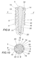
- FIG. 9 shows a further alteration of a projectile with an associated propellant cup in a longitudinal section
- FIG. 10 shows a section along line X-X of FIG. 9 .
- FIG. 11 shows a further embodiment of the projectile with an associated projectile cup in longitudinal section
- FIG. 12 shows a section along line XII-XII of FIG. 11 .
- FIG. 13 shows a projectile having a tail unit in a partially cutaway side view
- FIG. 14 shows the projectile from FIG. 13 in a section along line XIV-XIV of FIG. 13 ,
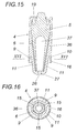
- FIG. 15 shows a further projectile form having a propellant cup in an axial section
- FIG. 16 shows a section along line XVI-XVI of FIG. 15 .
- the cartridge comprises a cartridge casing 1 having a base 2 and having a primer 3 inserted into the base 2 , as well as a propellant cup 4 , manufactured from plastic, for receiving a sub-caliber projectile 5 .
- the propellant cup 4 encloses the projectile 5 in a formfitting manner, which has a projectile body 6 , tapering toward the rear end, having a tail unit 7 in the form of radially projecting guide vanes 8 , and forms pockets 9 extending into the groin area between the guide vanes 8 and open toward the base 2 of the cartridge casing 1 , which are delimited on one side by a jacket 10 of the propellant cup 4 and on the other side by inner walls 11 , which press against the projectile 5 and separate the projectile in relation to a propellant charge, which is provided in the cartridge casing 1 between the base 2 and the propellant cup 4 and fills up the pockets 9 .
- this propellant charge is not shown in the drawing for reasons of clarity.
- the inner walls 11 delimiting the pockets 9 taper off into a cutting edge 12 .
- the jacket 10 of the propellant cup 4 has a jacket surface 13 tapering forward, which is provided with longitudinal ribs 14 distributed around the circumference, whose envelope surface corresponds to an envelope cylinder of the propellant cup 4 , so that they taper off flat toward the rear end of the jacket 10 , as may be inferred from FIG. 2 in particular.
- a good guide of the propellant cup 4 which is driven with the aid of the propellant gases out of a barrel of a shotgun, for example, is ensured by these longitudinal ribs 14 in spite of the jacket surface 13 tapering forward, which makes the passage of the propellant cup 4 and the projectile 5 through a possibly constricted muzzle opening of the barrel easier.
- separation points 15 in the form of axial slots are provided distributed around the circumference of the jacket 10 of the propellant cup 4 , so that the jacket 10 spreads apart like an umbrella and is decelerated after the exit from the barrel because of the air resistance.
- These separation points 15 which may also be implemented as intended breakpoints, also may not impair the seal between the jacket 10 of the propellant cup 4 and the barrel, of course, because the expulsion force is a function of this seal. Therefore, if the separation points 15 are extended axially to the rear beyond a preferably provided seal ring 16 , as indicated in FIGS. 2 and 4 , a seal closed around the circumference is ensured by the axial seal sections 17 enclosing the rear end of the separation points 15 .
- the projectile 5 forms a setback annular shoulder 19 on its head 18 , which is overlapped by the jacket 10 of the propellant cup 4 .
- the projectile 5 is thus axially fixed in the propellant cup 4 and may be inserted together with the propellant cup 4 in the cartridge casing 1 .
- the retention of the propellant cup 4 together with the projectile 5 in the cartridge casing 1 is achieved in a typical manner by a folded-over edge 20 of the cartridge casing 1 , as may be inferred from FIG. 1 .
- the axial support of the jacket 10 of the propellant cup 4 on the annular shoulder 19 of the projectile head 18 is not only used for axially fixing the projectile 5 within the propellant cup 4 , but rather also causes relief of the jacket 10 from axial pressure forces which are incident on the jacket 10 via the propellant cup 4 impinged by the propellant gases as the projectile 5 is driven out.
- the jacket 10 is to ensure a minimum deformation to improve the seal action between the jacket 10 and the barrel through the propellant gas pressure active in the area of the pockets 9 .
- the projectile 5 may be supported in the axial direction on the base of the propellant cup 4 via damping elements 21 .
- damping elements 21 are provided in the form of damping ribs 22 , which run transversely to the guide vanes 8 of the projectile 5 .
- the embodiment according to FIG. 5 differs from that according to FIGS. 1 through 4 above all in that the jacket 10 of the propellant cup 4 extends essentially over the entire length of the propellant cup 4 , which causes the disadvantage of a smaller receptacle volume for the propellant charge in comparison to inner walls 11 projecting axially beyond the jacket 10 according to the exemplary embodiment from FIGS. 1 through 4 , but has the advantage of obtaining a continuous guide of the propellant cup 4 in the barrel over the axial length of the propellant cup 4 , without having to provide additional design measures for this purpose.
- the inner walls 11 carry guide ribs 23 projecting beyond the jacket 10 in the axial direction in extension of the jacket 10 for this purpose.
- the projectile 5 corresponding to FIG. 5 is also equipped with a tail unit 7 forming guide vanes 8 .
- the projectile head 18 does not have an annular shoulder 19 , however.
- the axial fixing of the projectile 5 in the propellant cup 4 is performed by a concave inner wall 24 of the propellant cup jacket 10 which overlaps the convex head 18 .
- the projectile 5 according to FIG. 6 is provided with a tracer unit 25 , but otherwise essentially corresponds to that according to FIGS. 1 through 4 .
- the propellant cup 4 forms an overflow channel 27 closed by a diaphragm 26 for the propellant gases, which break through the diaphragm 26 when impinging the propellant cup 4 and ensure ignition of the tracer unit 25 .
- the projectiles 5 may be tailored and designed in manifold forms for various conditions, as illustrated in FIGS. 7 through 16 in several exemplary embodiments.
- the propellant cup 4 is to be tailored in each case to the projectile shape.
- FIG. 7 shows a projectile 5 which is formed by a hollow rotating body and obtains its flight guiding by mantle recesses 29 originating from the base-side face of the projectile jacket 28 , through which the pockets 9 of the propellant cup 4 extend.
- an extension 31 of the propellant cup 4 having an overflow channel 27 which opens into the cavity 30 of the projectile 5 projects into the base-side cavity of the projectile.
- the diaphragm 26 is again broken through, so that a corresponding gas pressure may build up in the cavity 30 as the projectile 5 is driven out of a barrel, which supports the detachment of the propellant cup 4 from the projectile 5 , which flies further, after the propellant cup 4 exits from the barrel.
- a projectile 5 which is cylindrical in its basic shape is provided, which has a centric recess 32 in the projectile base, into which a pocket 9 of the propellant cup 4 extends.
- the base of the pocket 9 is provided with an overflow channel 27 enclosed by a diaphragm 26 , which opens into a cavity 30 of the projectile 5 adjoining the recess 32 , to be able to use the gas pressure building up in the cavity 30 after the diaphragm 26 is broken through to detach the propellant cup 4 from the projectile 5 , as soon as the propellant cup 4 exits with the projectile 5 from the barrel.
- the projectile 5 may be provided with axial ribbing extending around the circumference.
- FIGS. 9 and 10 discloses a projectile 5 which has a star-shaped cross-section, which represents a continuous tail unit over the projectile length.
- the pockets 9 of the projectile cup 4 accordingly engage in the groin area between the star-shaped wings 33 of the projectile 5 .
- the pocket base 34 is implemented as reinforced, however, so that the impingement pressure by the propellant gases may be absorbed by the propellant cup 4 , which may only be supported at its rear end on the star-shaped wings 33 of the projectile 5 .
- the projectile according to FIGS. 11 and 12 differs from that according to FIGS. 9 and 10 above all in that it was manufactured from a tubular body, which was folded radially inward to form the axial wings 33 , as may be inferred from FIG. 12 in particular.
- the external shape of the projectile 5 thus corresponds to that according to FIGS. 9 and 10 , so that a corresponding propellant cup 4 also results.
- the remaining cavity of the folded-in tubular body may be filled up by a metal 35 .
- a projectile form having a tail unit 7 made of guide vanes 8 one may began with a hollow body open toward the propellant cup 4 , which is folded in to form guide vanes 8 as shown in FIGS. 13 and 14 , into three guide vanes 8 according to the exemplary embodiment.
- FIG. 14 these folded-in guide vanes 8 are illustrated, the inner walls 11 of the propellant cup 4 delimiting the pockets 9 being indicated by dot-dash lines.
- a projectile 5 is not manufactured in one piece, but rather comprises a head 18 and a tail unit 7 inserted into the hollow head 18 , whose guide vanes 8 extend up into the head area, as illustrated in FIGS. 4 through 6 , for example.
- the head 18 To connect the head 18 to the tail unit 7 , the head 18 solely has to be folded clamped into the groin area between the guide vanes 8 , a continuous shape of the guide vanes 8 from the projectile head 18 to the tail unit 7 resulting.
- This two-part embodiment of the projectile 5 allows the use of different projectile heads 18 with a corresponding tail unit 7 in each case.
- the annular chamber resulting between this projectile 5 and the jacket 10 of the propellant cup 4 may be used as the receptacle pocket 9 for receiving a part of the propellant charge.
- This annular chamber may experience a subdivision through the axial longitudinal slots of the separation points 15 , as may be inferred from FIG. 16 .
- the pockets 9 may not have any passage points to the outside in the area of the jacket 10 .
- Such a projectile 5 offers a comparative storage volume using its central cavity 37 to fire a resource to the target.
- the propellant cup 4 may detach more easily from the projectile 5 , a continuous flat contact of the projectile body on the jacket 10 of the propellant cup may be dispensed with and the propellant cup 4 may be provided with axial ribbing 36 , as illustrated in FIGS. 15 and 16 , for example.
Landscapes
- Engineering & Computer Science (AREA)
- General Engineering & Computer Science (AREA)
- Physics & Mathematics (AREA)
- Fluid Mechanics (AREA)
- Toys (AREA)
- Containers And Packaging Bodies Having A Special Means To Remove Contents (AREA)
- Closures For Containers (AREA)
Applications Claiming Priority (4)
| Application Number | Priority Date | Filing Date | Title |
|---|---|---|---|
| AT1674/2005 | 2005-10-13 | ||
| AT0167405A AT502547B1 (de) | 2005-10-13 | 2005-10-13 | Patrone |
| ATA1674/2005 | 2005-10-13 | ||
| PCT/AT2006/000421 WO2007041740A2 (de) | 2005-10-13 | 2006-10-12 | Patrone |
Publications (2)
| Publication Number | Publication Date |
|---|---|
| US20090064887A1 US20090064887A1 (en) | 2009-03-12 |
| US8037830B2 true US8037830B2 (en) | 2011-10-18 |
Family
ID=37685293
Family Applications (1)
| Application Number | Title | Priority Date | Filing Date |
|---|---|---|---|
| US12/083,319 Expired - Fee Related US8037830B2 (en) | 2005-10-13 | 2006-10-12 | Cartridge |
Country Status (5)
| Country | Link |
|---|---|
| US (1) | US8037830B2 (de) |
| EP (1) | EP1934549B1 (de) |
| AT (2) | AT502547B1 (de) |
| RU (1) | RU2419760C2 (de) |
| WO (1) | WO2007041740A2 (de) |
Cited By (3)
| Publication number | Priority date | Publication date | Assignee | Title |
|---|---|---|---|---|
| US20110030571A1 (en) * | 2008-03-13 | 2011-02-10 | Korea Nuclear Engineering Co., Ltd. | Ammunition |
| US20170205213A1 (en) * | 2014-08-26 | 2017-07-20 | Renat Abdulberovich Yusupov | Caliber shell with rigid mounting to housing of stabilizing fins |
| US10502515B2 (en) * | 2017-01-17 | 2019-12-10 | Raytheon Company | Launch piston brake |
Families Citing this family (3)
| Publication number | Priority date | Publication date | Assignee | Title |
|---|---|---|---|---|
| DE102014019198A1 (de) * | 2014-12-19 | 2016-06-23 | Diehl Bgt Defence Gmbh & Co. Kg | Geschoss |
| US10443990B2 (en) * | 2017-06-08 | 2019-10-15 | Connor Yadon | Fragmenting shotgun projectile with radially-disposed segments |
| RU2738519C2 (ru) * | 2019-03-11 | 2020-12-14 | Виталий Анатольевич Денисов | Поддон снаряда съемный |
Citations (52)
| Publication number | Priority date | Publication date | Assignee | Title |
|---|---|---|---|---|
| US34950A (en) * | 1862-04-15 | Improvement in expanding sabots for hot shot | ||
| US178595A (en) * | 1876-06-13 | Improvement in projectiles for ordnance | ||
| US193657A (en) * | 1877-07-31 | Improvement in projectiles | ||
| US214843A (en) * | 1879-04-29 | Improvement in projectiles for rifled guns | ||
| US1166360A (en) * | 1915-05-22 | 1915-12-28 | Eli E Gregory | Gun cartridge and projectile. |
| US2247563A (en) * | 1939-10-18 | 1941-07-01 | Robert S Spalding | Projectile |
| US2669930A (en) * | 1946-01-05 | 1954-02-23 | Remington Arms Co Inc | Sabot projectile |
| US2982212A (en) * | 1955-12-29 | 1961-05-02 | Jr Ralph O Robinson | Base fuze protector |
| US2991719A (en) * | 1944-06-24 | 1961-07-11 | Millar John Mcg | Projectile |
| US2993444A (en) * | 1945-08-02 | 1961-07-25 | Charles E Hablutzel | Sabot retainer |
| US3055268A (en) * | 1960-12-08 | 1962-09-25 | Rosenthal Henry | Discarding obturator and rotator for projectiles |
| US3164092A (en) * | 1962-11-13 | 1965-01-05 | Remington Arms Co Inc | Ammunition sabot |
| US3242866A (en) * | 1964-09-25 | 1966-03-29 | Richard L Malter | Primary and secondary projectile |
| US3318244A (en) | 1965-07-01 | 1967-05-09 | Charles E Rostocil | Cartridge |
| US3394905A (en) * | 1964-12-22 | 1968-07-30 | Dynamit Nobel Ag | Shotgun bullet |
| US3431815A (en) * | 1968-01-24 | 1969-03-11 | Us Army | Discardable rotating band |
| US3496869A (en) * | 1967-07-28 | 1970-02-24 | Oerlikon Buehrle Holding Ag | Sabot projectile |
| DE2630830A1 (de) | 1976-07-09 | 1978-01-19 | Dynamit Nobel Ag | Treibspiegelgeschoss |
| US4175493A (en) * | 1977-11-07 | 1979-11-27 | John Daily | Patch for muzzle loading firearms |
| US4177733A (en) * | 1976-09-20 | 1979-12-11 | Rheinmetall Gmbh. | Spin stabilized projectile assembly |
| US4249466A (en) * | 1977-07-21 | 1981-02-10 | Werkzeugmaschinenfabrik Oerlikon-Buhrle Ag | Sabot projectile having a pyrotechnic composition |
| US4434718A (en) | 1981-09-11 | 1984-03-06 | Kopsch Paul J | Sabot and projectile |
| DE2836963A1 (de) | 1978-08-24 | 1984-03-08 | Rheinmetall GmbH, 4000 Düsseldorf | Munition-einheit fuer rohrwaffen |
| EP0143720A1 (de) | 1983-11-29 | 1985-06-05 | Jean-Claude Sauvestre | Munition für Jagdgewehr |
| US4643099A (en) * | 1980-10-04 | 1987-02-17 | Rheinmetall Gmbh | Armored-piercing projectile (penetrator) |
| US4709638A (en) * | 1981-09-24 | 1987-12-01 | Honeywell Inc. | Discarding sabot projectile |
| US4846068A (en) * | 1986-07-08 | 1989-07-11 | Steyr-Daimler-Puch Aktiengesellschaft | Cartridge for firearms |
| DE3811597A1 (de) | 1988-04-07 | 1989-10-19 | Dynamit Nobel Ag | Treibkaefig fuer ein unterkalibergeschoss |
| DE3824524A1 (de) | 1988-07-20 | 1990-02-08 | Wegmann & Co | Panzerbrechendes geschoss |
| US4936220A (en) | 1989-07-03 | 1990-06-26 | The United States Of America As Represented By The Secretary Of The Army | Solid propellant-carrying caboted projectile |
| US4974517A (en) * | 1988-12-22 | 1990-12-04 | Diehl Gmbh & Co. | Ammunition with propulsion mechanism |
| US5090328A (en) * | 1990-08-25 | 1992-02-25 | Rheinmetall Gmbh | Spin stabilized projectile unit |
| US5157224A (en) * | 1989-06-01 | 1992-10-20 | Giat Industries | Device for holding and guiding a sub-projectile in a cylindrical casing and in a weapon barrel |
| US5189251A (en) * | 1992-01-29 | 1993-02-23 | The United States Of America As Represented By The Secretary Of The Army | Sabot for high dispersion shot shell |
| US5192830A (en) * | 1992-01-29 | 1993-03-09 | The United States Of America As Represented By The Secretary Of The Army | Sabot for high dispersion shot shell |
| US5214238A (en) * | 1992-03-23 | 1993-05-25 | Christopher Young | Sabot for chambering conventional bullets in a shotgun |
| US5339743A (en) | 1993-07-12 | 1994-08-23 | Remington Arms Company, Inc. | Ammunition system comprising slug holding sabot and slug type shot shell |
| US5359938A (en) * | 1990-10-24 | 1994-11-01 | Olin Corporation | Ultra light weight sabot |
| US5404816A (en) * | 1993-09-24 | 1995-04-11 | Oerlikon-Contraves Pyrotec Ag | Releasable sabot for a subcaliber projectile |
| US5415102A (en) * | 1994-05-13 | 1995-05-16 | White; Gary B. | Muzzle loading sabot |
| US5710391A (en) * | 1993-10-12 | 1998-01-20 | Chetcuti; Francis | Recoil reducer wad for ammunition |
| US5804759A (en) | 1994-10-26 | 1998-09-08 | Sauvestre; Jean-Claude | Hunting bullet having a telescoping flechette and comprising a sub-projectile connected to a launcher |
| US6073560A (en) | 1998-03-09 | 2000-06-13 | Remington Arms Company, Inc. | Sabot |
| US20010047736A1 (en) | 1997-09-23 | 2001-12-06 | Rheinmetall W & M Gmbh, Heinrich-Ehrhardt-Strasse | Cartridge ammunition |
| US20030167957A1 (en) * | 2001-11-24 | 2003-09-11 | Thomas Heitmann | Projectile |
| US20040182274A1 (en) * | 2003-03-20 | 2004-09-23 | Hornady Manufacturing Company | Sabot for muzzleloading firearm |
| US20060278114A1 (en) | 2005-05-16 | 2006-12-14 | Hornady Manufacturing Company | Shotgun shell with slug |
| US20070012212A1 (en) * | 2005-07-12 | 2007-01-18 | Sheaffer Clifford G | Shot pattern control wad structure for shotshell |
| US7331294B2 (en) * | 2002-09-25 | 2008-02-19 | Brenneke Gmbh & Co. Kg | Rifled slug |
| US7451705B2 (en) * | 2004-03-17 | 2008-11-18 | Fry Grant R | Non-discarding sabot projectile system |
| US7451706B2 (en) * | 2005-01-25 | 2008-11-18 | Olin Corporation | Short magnum shotshell cartridge and firing assembly |
| US20090151593A1 (en) * | 2005-10-13 | 2009-06-18 | Udo Winter | Sub-Caliber Projectile |
-
2005
- 2005-10-13 AT AT0167405A patent/AT502547B1/de not_active IP Right Cessation
-
2006
- 2006-10-12 RU RU2008118477/11A patent/RU2419760C2/ru not_active IP Right Cessation
- 2006-10-12 US US12/083,319 patent/US8037830B2/en not_active Expired - Fee Related
- 2006-10-12 WO PCT/AT2006/000421 patent/WO2007041740A2/de active Application Filing
- 2006-10-12 AT AT06804349T patent/ATE534013T1/de active
- 2006-10-12 EP EP06804349A patent/EP1934549B1/de not_active Not-in-force
Patent Citations (58)
| Publication number | Priority date | Publication date | Assignee | Title |
|---|---|---|---|---|
| US34950A (en) * | 1862-04-15 | Improvement in expanding sabots for hot shot | ||
| US178595A (en) * | 1876-06-13 | Improvement in projectiles for ordnance | ||
| US193657A (en) * | 1877-07-31 | Improvement in projectiles | ||
| US214843A (en) * | 1879-04-29 | Improvement in projectiles for rifled guns | ||
| US1166360A (en) * | 1915-05-22 | 1915-12-28 | Eli E Gregory | Gun cartridge and projectile. |
| US2247563A (en) * | 1939-10-18 | 1941-07-01 | Robert S Spalding | Projectile |
| US2991719A (en) * | 1944-06-24 | 1961-07-11 | Millar John Mcg | Projectile |
| US2993444A (en) * | 1945-08-02 | 1961-07-25 | Charles E Hablutzel | Sabot retainer |
| US2669930A (en) * | 1946-01-05 | 1954-02-23 | Remington Arms Co Inc | Sabot projectile |
| US2982212A (en) * | 1955-12-29 | 1961-05-02 | Jr Ralph O Robinson | Base fuze protector |
| US3055268A (en) * | 1960-12-08 | 1962-09-25 | Rosenthal Henry | Discarding obturator and rotator for projectiles |
| US3164092A (en) * | 1962-11-13 | 1965-01-05 | Remington Arms Co Inc | Ammunition sabot |
| US3242866A (en) * | 1964-09-25 | 1966-03-29 | Richard L Malter | Primary and secondary projectile |
| US3394905A (en) * | 1964-12-22 | 1968-07-30 | Dynamit Nobel Ag | Shotgun bullet |
| US3318244A (en) | 1965-07-01 | 1967-05-09 | Charles E Rostocil | Cartridge |
| US3496869A (en) * | 1967-07-28 | 1970-02-24 | Oerlikon Buehrle Holding Ag | Sabot projectile |
| US3431815A (en) * | 1968-01-24 | 1969-03-11 | Us Army | Discardable rotating band |
| DE2630830A1 (de) | 1976-07-09 | 1978-01-19 | Dynamit Nobel Ag | Treibspiegelgeschoss |
| US4142467A (en) * | 1976-07-09 | 1979-03-06 | Dynamit Nobel Aktiengesellschaft | Projectile with sabot |
| US4177733A (en) * | 1976-09-20 | 1979-12-11 | Rheinmetall Gmbh. | Spin stabilized projectile assembly |
| US4249466A (en) * | 1977-07-21 | 1981-02-10 | Werkzeugmaschinenfabrik Oerlikon-Buhrle Ag | Sabot projectile having a pyrotechnic composition |
| US4175493A (en) * | 1977-11-07 | 1979-11-27 | John Daily | Patch for muzzle loading firearms |
| DE2836963A1 (de) | 1978-08-24 | 1984-03-08 | Rheinmetall GmbH, 4000 Düsseldorf | Munition-einheit fuer rohrwaffen |
| US4444114A (en) | 1978-08-24 | 1984-04-24 | Rheinmetall Gmbh | Munitions round for barrel-type weapons |
| US4542696A (en) | 1978-08-24 | 1985-09-24 | Rheinmetall Gmbh | Munitions round for barrel-type weapons |
| US4643099A (en) * | 1980-10-04 | 1987-02-17 | Rheinmetall Gmbh | Armored-piercing projectile (penetrator) |
| US4434718A (en) | 1981-09-11 | 1984-03-06 | Kopsch Paul J | Sabot and projectile |
| US4709638A (en) * | 1981-09-24 | 1987-12-01 | Honeywell Inc. | Discarding sabot projectile |
| EP0143720A1 (de) | 1983-11-29 | 1985-06-05 | Jean-Claude Sauvestre | Munition für Jagdgewehr |
| US4846068A (en) * | 1986-07-08 | 1989-07-11 | Steyr-Daimler-Puch Aktiengesellschaft | Cartridge for firearms |
| US4953466A (en) | 1988-04-07 | 1990-09-04 | Dynamit Nobel Aktiengesellschaft | Propulsion cage for a subcaliber projectile |
| DE3811597A1 (de) | 1988-04-07 | 1989-10-19 | Dynamit Nobel Ag | Treibkaefig fuer ein unterkalibergeschoss |
| DE3824524A1 (de) | 1988-07-20 | 1990-02-08 | Wegmann & Co | Panzerbrechendes geschoss |
| US4974517A (en) * | 1988-12-22 | 1990-12-04 | Diehl Gmbh & Co. | Ammunition with propulsion mechanism |
| US5157224A (en) * | 1989-06-01 | 1992-10-20 | Giat Industries | Device for holding and guiding a sub-projectile in a cylindrical casing and in a weapon barrel |
| US4936220A (en) | 1989-07-03 | 1990-06-26 | The United States Of America As Represented By The Secretary Of The Army | Solid propellant-carrying caboted projectile |
| US5090328A (en) * | 1990-08-25 | 1992-02-25 | Rheinmetall Gmbh | Spin stabilized projectile unit |
| US5359938A (en) * | 1990-10-24 | 1994-11-01 | Olin Corporation | Ultra light weight sabot |
| US5189251A (en) * | 1992-01-29 | 1993-02-23 | The United States Of America As Represented By The Secretary Of The Army | Sabot for high dispersion shot shell |
| US5192830A (en) * | 1992-01-29 | 1993-03-09 | The United States Of America As Represented By The Secretary Of The Army | Sabot for high dispersion shot shell |
| US5214238A (en) * | 1992-03-23 | 1993-05-25 | Christopher Young | Sabot for chambering conventional bullets in a shotgun |
| US5339743A (en) | 1993-07-12 | 1994-08-23 | Remington Arms Company, Inc. | Ammunition system comprising slug holding sabot and slug type shot shell |
| US5404816A (en) * | 1993-09-24 | 1995-04-11 | Oerlikon-Contraves Pyrotec Ag | Releasable sabot for a subcaliber projectile |
| US5710391A (en) * | 1993-10-12 | 1998-01-20 | Chetcuti; Francis | Recoil reducer wad for ammunition |
| US5415102A (en) * | 1994-05-13 | 1995-05-16 | White; Gary B. | Muzzle loading sabot |
| US5804759A (en) | 1994-10-26 | 1998-09-08 | Sauvestre; Jean-Claude | Hunting bullet having a telescoping flechette and comprising a sub-projectile connected to a launcher |
| US20010047736A1 (en) | 1997-09-23 | 2001-12-06 | Rheinmetall W & M Gmbh, Heinrich-Ehrhardt-Strasse | Cartridge ammunition |
| US6073560A (en) | 1998-03-09 | 2000-06-13 | Remington Arms Company, Inc. | Sabot |
| US6712005B2 (en) * | 2001-11-24 | 2004-03-30 | Rheinmetall W & M Gmbh | Projectile |
| US20030167957A1 (en) * | 2001-11-24 | 2003-09-11 | Thomas Heitmann | Projectile |
| US7331294B2 (en) * | 2002-09-25 | 2008-02-19 | Brenneke Gmbh & Co. Kg | Rifled slug |
| US20040182274A1 (en) * | 2003-03-20 | 2004-09-23 | Hornady Manufacturing Company | Sabot for muzzleloading firearm |
| US6895865B2 (en) * | 2003-03-20 | 2005-05-24 | Hornady Manufacturing Company | Sabot for muzzleloading firearm |
| US7451705B2 (en) * | 2004-03-17 | 2008-11-18 | Fry Grant R | Non-discarding sabot projectile system |
| US7451706B2 (en) * | 2005-01-25 | 2008-11-18 | Olin Corporation | Short magnum shotshell cartridge and firing assembly |
| US20060278114A1 (en) | 2005-05-16 | 2006-12-14 | Hornady Manufacturing Company | Shotgun shell with slug |
| US20070012212A1 (en) * | 2005-07-12 | 2007-01-18 | Sheaffer Clifford G | Shot pattern control wad structure for shotshell |
| US20090151593A1 (en) * | 2005-10-13 | 2009-06-18 | Udo Winter | Sub-Caliber Projectile |
Non-Patent Citations (1)
| Title |
|---|
| International Search Report. |
Cited By (5)
| Publication number | Priority date | Publication date | Assignee | Title |
|---|---|---|---|---|
| US20110030571A1 (en) * | 2008-03-13 | 2011-02-10 | Korea Nuclear Engineering Co., Ltd. | Ammunition |
| US8485100B2 (en) * | 2008-03-13 | 2013-07-16 | Korea Nuclear Engineering Co., Ltd. | Ammunition |
| US20170205213A1 (en) * | 2014-08-26 | 2017-07-20 | Renat Abdulberovich Yusupov | Caliber shell with rigid mounting to housing of stabilizing fins |
| US9958241B2 (en) * | 2014-08-26 | 2018-05-01 | Renat Abdulberovich Yusupov | Caliber shell with rigid mounting to housing of stabilizing fins |
| US10502515B2 (en) * | 2017-01-17 | 2019-12-10 | Raytheon Company | Launch piston brake |
Also Published As
| Publication number | Publication date |
|---|---|
| RU2419760C2 (ru) | 2011-05-27 |
| WO2007041740A2 (de) | 2007-04-19 |
| EP1934549A2 (de) | 2008-06-25 |
| WO2007041740A3 (de) | 2007-07-12 |
| RU2008118477A (ru) | 2009-11-20 |
| AT502547B1 (de) | 2009-10-15 |
| ATE534013T1 (de) | 2011-12-15 |
| AT502547A1 (de) | 2007-04-15 |
| US20090064887A1 (en) | 2009-03-12 |
| EP1934549B1 (de) | 2011-11-16 |
Similar Documents
| Publication | Publication Date | Title |
|---|---|---|
| US20220214148A1 (en) | Polymer ammunition having a projectile made by metal injection molding | |
| US20200363173A1 (en) | Metal injection molded ammunition cartridge | |
| US10591260B2 (en) | Polymer ammunition having a projectile made by metal injection molding | |
| US4142467A (en) | Projectile with sabot | |
| US8037830B2 (en) | Cartridge | |
| US10041770B2 (en) | Metal injection molded ammunition cartridge | |
| US10081057B2 (en) | Method of making a projectile by metal injection molding | |
| US6105506A (en) | Sabot slug for shotgun | |
| US9395163B2 (en) | Hollow slug and casing | |
| US6799519B2 (en) | Sabot for a bullet | |
| US20070119330A1 (en) | Lead Attached Sabot Slug | |
| US6158348A (en) | Propellant configuration | |
| US9797695B2 (en) | Cartridge | |
| JP2016528464A (ja) | 発射体本体及びそれを伴う小火器用又は軽火器用弾丸 | |
| AU613001B2 (en) | Projectile with tracer | |
| US5804759A (en) | Hunting bullet having a telescoping flechette and comprising a sub-projectile connected to a launcher | |
| US6543363B2 (en) | Primer tube for artillery ammunition | |
| NO162738B (no) | Underkaliberprosjektil med drivbur og oppdelbar forpenetrator. | |
| US4388868A (en) | Shell body for fin-stabilized projectiles | |
| FI73829B (fi) | Granatkropp foer vingstabiliserade projektiler. | |
| US20110168048A1 (en) | Multi-Faceted Structure for Bombs and Warheads Including Penetrating Warheads | |
| CZ9900559A3 (cs) | Projektil | |
| NZ720372B2 (en) | Cartridge | |
| JPH05196398A (ja) | ケース入り入子式弾薬 |
Legal Events
| Date | Code | Title | Description |
|---|---|---|---|
| REMI | Maintenance fee reminder mailed | ||
| LAPS | Lapse for failure to pay maintenance fees | ||
| STCH | Information on status: patent discontinuation |
Free format text: PATENT EXPIRED DUE TO NONPAYMENT OF MAINTENANCE FEES UNDER 37 CFR 1.362 |
|
| FP | Lapsed due to failure to pay maintenance fee |
Effective date: 20151018 |