US8031585B2 - Communication apparatus - Google Patents
Communication apparatus Download PDFInfo
- Publication number
- US8031585B2 US8031585B2 US12/466,825 US46682509A US8031585B2 US 8031585 B2 US8031585 B2 US 8031585B2 US 46682509 A US46682509 A US 46682509A US 8031585 B2 US8031585 B2 US 8031585B2
- Authority
- US
- United States
- Prior art keywords
- stbc
- signals
- signal
- predetermined number
- unit configured
- Prior art date
- Legal status (The legal status is an assumption and is not a legal conclusion. Google has not performed a legal analysis and makes no representation as to the accuracy of the status listed.)
- Expired - Fee Related, expires
Links
Images


Classifications
-
- H—ELECTRICITY
- H04—ELECTRIC COMMUNICATION TECHNIQUE
- H04B—TRANSMISSION
- H04B17/00—Monitoring; Testing
- H04B17/0082—Monitoring; Testing using service channels; using auxiliary channels
- H04B17/0085—Monitoring; Testing using service channels; using auxiliary channels using test signal generators
-
- H—ELECTRICITY
- H04—ELECTRIC COMMUNICATION TECHNIQUE
- H04B—TRANSMISSION
- H04B7/00—Radio transmission systems, i.e. using radiation field
- H04B7/02—Diversity systems; Multi-antenna system, i.e. transmission or reception using multiple antennas
- H04B7/04—Diversity systems; Multi-antenna system, i.e. transmission or reception using multiple antennas using two or more spaced independent antennas
- H04B7/06—Diversity systems; Multi-antenna system, i.e. transmission or reception using multiple antennas using two or more spaced independent antennas at the transmitting station
- H04B7/0613—Diversity systems; Multi-antenna system, i.e. transmission or reception using multiple antennas using two or more spaced independent antennas at the transmitting station using simultaneous transmission
- H04B7/0667—Diversity systems; Multi-antenna system, i.e. transmission or reception using multiple antennas using two or more spaced independent antennas at the transmitting station using simultaneous transmission of delayed versions of same signal
- H04B7/0669—Diversity systems; Multi-antenna system, i.e. transmission or reception using multiple antennas using two or more spaced independent antennas at the transmitting station using simultaneous transmission of delayed versions of same signal using different channel coding between antennas
-
- H—ELECTRICITY
- H04—ELECTRIC COMMUNICATION TECHNIQUE
- H04L—TRANSMISSION OF DIGITAL INFORMATION, e.g. TELEGRAPHIC COMMUNICATION
- H04L1/00—Arrangements for detecting or preventing errors in the information received
- H04L1/02—Arrangements for detecting or preventing errors in the information received by diversity reception
- H04L1/06—Arrangements for detecting or preventing errors in the information received by diversity reception using space diversity
- H04L1/0618—Space-time coding
- H04L1/0625—Transmitter arrangements
-
- H—ELECTRICITY
- H04—ELECTRIC COMMUNICATION TECHNIQUE
- H04L—TRANSMISSION OF DIGITAL INFORMATION, e.g. TELEGRAPHIC COMMUNICATION
- H04L1/00—Arrangements for detecting or preventing errors in the information received
- H04L1/02—Arrangements for detecting or preventing errors in the information received by diversity reception
- H04L1/06—Arrangements for detecting or preventing errors in the information received by diversity reception using space diversity
- H04L1/0618—Space-time coding
- H04L1/0631—Receiver arrangements
-
- H—ELECTRICITY
- H04—ELECTRIC COMMUNICATION TECHNIQUE
- H04L—TRANSMISSION OF DIGITAL INFORMATION, e.g. TELEGRAPHIC COMMUNICATION
- H04L1/00—Arrangements for detecting or preventing errors in the information received
- H04L1/24—Testing correct operation
Definitions
- the present invention relates to a communication apparatus using space time coding for information communication, and more particularly to a communication apparatus configured to transmit or receive a space time code to test the receiving state of a receiver.
- MIMO Multiple Input Multiple Output
- STBC Space-Time Block Code
- a receiver can perform symbol separation by use of a simple linear calculation with respect to encoding by a transmitter, and also a maximum transmit diversity effect equivalent to the maximum ratio composition can be achieved.
- a maximum transmit diversity effect equivalent to the maximum ratio composition can be achieved.
- a communication apparatus includes: a transmitter having a plurality of transmitting units configured to perform data transmission, each transmitting unit including a synchronization unit configured to synchronize the transmitting units, an STBC test unit configured to divide an input signal to produce a plurality of STBC signals in order to perform an STBC test, and a controlling unit configured to perform a setting to test mode, wherein in the test mode, the transmitting units are combined to transmit an STBC signal; and a receiver configured to receive the STBC signal.
- a communication apparatus includes: a transmitter including a transmitting unit configured to receive a first and second signals of at least two types, and firstly divide the first signal into a predetermined number of STBC signals and combine a predetermined number of the STBC signals being the result of the division and transmit the STBC signals as a first composite signal and subsequently divide the second signal into a predetermined number of STBC signals and combine a predetermined number of the STBC signals being the result of the division and transmit the STBC signals as a second composite signal; and a receiver including a receiving unit configured to receive, in a time series order, at least the first and second composite signals sequentially transmitted from the transmitter and thereafter process a predetermined number of the STBC signals for each of the first and second composite signals and thereby perform decoding to reproduce at least the first and second original signals.
- FIG. 1 is a block diagram illustrating a communication apparatus according to a first embodiment of the present invention
- FIGS. 2A to 2D are each a view for describing an example of the number of antennas for each of the transmitting unit and the receiving unit of FIG. 1 ;
- FIG. 4 is a view illustrating an example of MIMO technique
- FIG. 5 is a view illustrating an STBC transmit image according to the MIMO technique
- FIG. 6 is a view schematically illustrating the main part of the transmitting unit illustrated in FIG. 3 ;
- FIG. 7 is a block diagram illustrating an exemplary configuration of the STBC test unit of FIG. 1 ;
- FIG. 8 is a block diagram illustrating an exemplary configuration of the STBC signal composing unit of FIG. 7 ;
- FIG. 9 is a block diagram illustrating a communication apparatus according to a second embodiment of the present invention.
- FIG. 10 is a view illustrating an exemplary operation of the transmitting unit of FIG. 9 ;
- FIG. 11 is a view illustrating an STBC transmit image according to a pseudo-channel composing technique by the transmitting unit of FIG. 9 ;
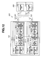
- FIG. 12 is a view illustrating an exemplary configuration of the communication apparatus when two transmitting units of FIG. 9 are used;
- FIG. 13 is a view illustrating an exemplary operation of the two transmitting units of FIG. 12 ;
- FIG. 14 is a view illustrating an STBC transmit image according to the pseudo-channel composing technique by the two transmitting units of FIG. 12 ;
- FIG. 15 is a block diagram illustrating a communication apparatus according to a third embodiment of the present invention.
- FIG. 16 is a view illustrating an exemplary operation of the receiving unit of FIG. 15 .
- FIG. 1 is a block diagram illustrating a communication apparatus according to a first embodiment of the present invention.
- a communication apparatus 300 includes a transmitter 100 configured to transmit an STBC signal and an STBC receiver 200 configured to receive the transmitted STBC signal.
- the transmitter 100 includes an n-number of transmitting units 101 - 1 to 101 - n.
- the transmitting units 101 - 1 to 101 - n each include an m-number of antennas 102 , synchronization units 104 - 1 to 104 - n configured to synchronize the transmitting units, STBC test units 105 - 1 to 105 - n configured to test transmitting and receiving of the STBC signal, and controlling units 103 - 1 to 103 - n configured to perform a setting to ordinary mode or test mode and also determine a mode.
- the n-number of transmitting units 101 - 1 to 101 - n each have an m-number of antennas, so the number of antennas is n ⁇ m in the whole transmitter 100 ; but for simplification of explanation, m is set to 1 in FIG.
- the STBC test unit 105 - 1 (typically, 105 - n ) divides an input signal (not illustrated) into a predetermined number (usually equal to the number n of transmitting antennas) of signals and sends the resultant signals to the respective STBC test units of each transmitting unit and produces a signal obtained by modulating a carrier of the same frequency with a signal having added thereto complex conjugate data needed when a receiver side recombines the signals being the result of the division.
- the produced signals are sent from the respective transmitting units in a manner synchronized with each other.
- the STBC receiver 200 is a related art MIMO receiver with a j-number of antennas 201 .
- signals received via the j-number of antennas 201 are received by a j-number of receiving units 202 - 1 to 202 - j , and an arithmetic processing unit (not illustrated) extracts from the j-number of receiving signals, the signals which are not yet subjected to the division, and rearranges the signals in the original order, whereby decoding is performed.
- the transmitting unit 101 - 1 is assumed to include an m-number of transmitting antennas.
- the transmitting units 101 - 2 to 101 - n are each also assumed to include an m-number of antennas.
- an n ⁇ m number of antennas are included in all.
- m is set to 1; thus, since the n-number of transmitting units each have one antenna, the whole transmitter 100 includes an n-number of antennas X 1 to Xn in all.
- the receiving unit 202 - 1 is assumed to include a k-number of receiving antennas.
- the receiving units 202 - 2 to 202 - j are each also assumed to include a k-number of antennas.
- a j ⁇ k number of antennas are included in all.
- k is set to 1; thus, since the j-number of receiving units each have one antenna, the whole receiver 200 includes a j-number of antennas r 1 to rj in all.
- the related art data transmission means, for example according to the above described wireless standard 11n, applying to an input signal, processings of convolution coding, interleaving, subcarrier modulation, inverse Fourier transform (IFFT), addition of guard interval and D/A conversion, and transmitting the processed signal.
- IFFT inverse Fourier transform
- test mode the transmitting units 101 - 1 to 101 - n transmit STBC signals produced by the STBC test units 105 - 1 to 105 - n in synchronization with the same synchronization timing of the synchronization units 104 - 1 to 104 - n . Accordingly, an STBC signal can be transmitted using a given antenna. The transmitted signal is received via the antenna 201 of the STBC receiver 200 and then decoded.
- synchronization unit 104 - 1 to 104 - n One synchronization unit produces a synchronization signal and sends the produced synchronization signal to the other synchronization units.
- the other synchronization units synchronize with each other in response to the synchronization signal.
- the method is not limited to that of the present embodiment, and another approach may be applied provided that the transmitting units 101 - 1 to 101 - n can transmit STBC signals in synchronization with each other.
- FIG. 3 illustrates an exemplary operation of the transmitting units according to the first embodiment.
- FIG. 3 is a view illustrating an exemplary operation in which STBC signals are transmitted via X 1 and X 2 of the antenna 102 connected to the transmitting units, wherein the number n of transmitting units in FIG. 1 is 2 and the number m of antennas of the transmitting units is 1.
- the controlling units 103 - 1 and 103 - 2 and synchronization units 104 - 1 and 104 - 2 are omitted in each of the transmitting units 101 - 1 and 101 - 2 .
- Input signal a 0 , a 1 is inputted to the STBC test unit 105 - 1 .
- the input signal is divided into two signals a 0 and a 1 , and data needed when the receiver side recombines the two signals is added to the two signals a 0 and a 1 . Thereafter, the signals are outputted as an STBC signal 1 and an STBC signal 2 .
- complex conjugate data is used (in FIG. 3 , * indicates complex conjugate).
- two antennas are needed, but the transmitting unit 101 - 1 includes only one antenna.
- the STBC signal 2 is sent from the STBC test unit 105 - 1 of the transmitting unit 101 - 1 to the STBC test unit 105 - 2 of the other transmitting unit 101 - 2 . Then, in synchronization with the same synchronization signal from the synchronization units 104 - 1 and 104 - 2 , the STBC signal 1 is transmitted via X 1 of the antenna 102 and the STBC signal 2 is transmitted via X 2 of the antenna 102 , whereby STBC transmission is performed.
- FIG. 4 illustrates an example of MIMO technique
- FIG. 5 illustrates an STBC transmit image according to the MIMO technique.
- the transmitter includes, as illustrated in FIG. 4 , an STBC encode unit and multiple (for example, two) antennas X 1 and X 2 .
- an input signal stream a 0 , a 1 is, as illustrated in FIG. 5 , inputted to the STBC encode unit, the input signal is divided into multiple (in this example, two) signal groups in a direction of time, and complex conjugate data ⁇ a* 1 and a* 0 are added to the signals a 0 and a 1 , respectively. Thereafter, carriers of the same frequency are separately modulated by the two signal data and transmitted via the antennas X 1 and X 2 .
- two radio waves obtained by modulating carriers of the same frequency with the two signal data are transmitted via the two antennas X 1 and X 2 in a mixed manner.
- the receiver refers to the complex conjugate data of the signal data which are mixed in the received two radio waves and thereby performs decoding to obtain a signal stream similar to the original input signal.
- FIG. 6 schematically illustrates the main part of the transmitter 100 illustrated in FIG. 3 .
- An STBC signal producing unit of FIG. 6 is included in the STBC test unit, and corresponds to an STBC encode unit and an STBC signal selecting unit to be described later.
- the two signal data being the result of division by the STBC test unit of the transmitting unit 101 - 1
- one is transmitted via the antenna X 1 of the transmitting unit 101 - 1 and the other is transmitted via the antenna X 2 of the transmitting unit 101 - 2 .
- STBC signals can be transmitted.
- the number of transmitting antennas can be easily adapted to any condition solely by combining multiple chips with one antenna; thus labor and cost for manufacturing specific chips with multiple antennas can be saved.
- FIG. 7 illustrates an exemplary configuration of the STBC test units 105 - 1 to 105 - n of FIG. 1 .
- the STBC test units 105 - 1 to 105 - n each include an STBC encode unit 31 - 1 to 31 - n configured to produce an STBC signal, an STBC signal selecting unit 32 - 1 to 32 - n configured to select and transmit a given STBC signal, and an STBC signal composing unit 33 - 1 to 33 - n capable of combining a given STBC signal.
- the first STBC test unit 105 - 1 includes the STBC encode unit 31 - 1 , the STBC signal selecting unit 32 - 1 , and the STBC signal composing unit 33 - 1 .
- the n-th STBC test unit 105 - n includes the STBC encode unit 31 - n , the STBC signal selecting unit 32 - n , and the STBC signal composing unit 33 - n.
- one of the STBC encode units 31 - 1 to 31 - n of the n-number of STBC test units 105 - 1 to 105 - n produces an STBC signal.
- the STBC signal is produced, for example, by inputting test data to the STBC encode unit. That is, the STBC signal produced by one of the STBC test units 105 - 1 to 105 - n can be outputted via the STBC signal selecting unit of that STBC test unit to one of the STBC signal composing unit of that STBC test unit and another STBC test unit, or to both the STBC signal composing unit of that STBC test unit and another STBC test unit.
- the determination on whether the STBC signal is to be outputted to one of the STBC signal composing unit of that STBC test unit and another STBC test unit, or to both the STBC signal composing unit of that STBC test unit and another STBC test unit is done by the controlling unit of the transmitting unit included in that STBC test unit. Further, the determination on which STBC test unit receives the STBC signal is also done by the controlling unit of the transmitting unit included in that STBC test unit.
- the STBC test units 105 - 1 to 105 - n are connected by cable to supply the STBC signal to the STBC test units. Accordingly, a given STBC signal can be outputted to a given STBC test unit.
- the STBC signal composing units 33 - 1 to 33 - n perform pseudo channel composition with respect to an input signal. Thus, the use of more antennas than the actual number of antennas is implemented in a pseudo manner. The pseudo channel composition will be described later with reference to FIG. 8 .
- the STBC test units each include the STBC encode unit, the STBC signal selecting unit and the STBC signal composing unit.
- an STBC signal can be transmitted.
- An exemplary method of producing an STBC signal has been described by which input data for testing is produced and then encoded by the STBC encode unit.
- another approach may be used provided that an STBC signal can be produced.
- the STBC test units 105 - 1 to 105 - n are connected by cable to supply an STBC signal.
- another approach may be used provided that a given STBC signal can be supplied to a given STBC test unit.
- STBC signal transmission by a given number of antennas can be done.
- FIG. 8 illustrates an exemplary configuration of the STBC signal composing units 33 - 1 to 33 - n of FIG. 7 .
- the STBC signal composing units 33 - 1 to 33 - n each include a storage unit 33 - 1 a to 33 - na configured to store an STBC signal selected in the preceding stage, and a pseudo channel composing unit 33 - 1 b to 33 - nb that can perform pseudo channel composition with respect to the STBC signal stored in the storage unit in test mode.
- the first STBC signal composing unit 33 - 1 includes the storage unit 33 - 1 a and the pseudo channel composing unit 33 - 1 b .
- the n-th STBC signal composing unit 33 - n includes the storage unit 33 - na and the pseudo channel composing unit 33 - nb .
- the expression “pseudo channel composition” means that pseudo channel composition is performed with respect to multiple STBC signals, whereby signals transmitted via multiple antennas in a pseudo manner are combined.
- test mode The operation in test mode will be described.
- an STBC signal selected (distributed) by the STBC signal selecting units 32 - 1 to 32 - n is stored in the storage units 33 - 1 a to 33 - na of the transmitting units 101 - 1 to 101 - n (or in one of the transmitting units 101 - 1 to 101 - n ).
- the STBC signals supplied to the storage units 33 - 1 a to 33 - na are supplied to the pseudo channel composing units 33 - 1 b to 33 - nb to perform pseudo channel composition.
- the storage units 33 - 1 a to 33 - na may be omitted. Consequently, even when the actual number of antennas is smaller than a, an operation can be implemented in which an STBC signal is transmitted via an a-number of antennas in a pseudo manner.
- multiple existing chips for example, 11n SISO chip
- multiple existing chips for example, 11n SISO chip
- the number of antennas can be increased for STBC signal transmission, allowing low-cost design.
- the transmitter and the receiver In STBC test, for example, when it is desired to increase the number of antennas, the transmitter and the receiver must be reconstructed. According to the present embodiment, however, the configuration can be flexibly modified to address the above problem and STBC signal transmission can be done with a given number of antennas. Since multiple transmitting units are combined to constitute a transmitter, STBC signal transmission can be done with a given number of antennas, so that the cost for test circuit reconstruction can be saved. A test function is added to an existing transmitter/receiver, whereby a test using STBC can be performed with a given number of antennas. Accordingly, the effect of design cost reduction is achieved.
- a given number of STBC signals are produced in the transmitter and pseudo channel composition is performed with respect to the STBC signals, whereby even when a needed number (a) of antennas is not provided, a composite STBC signal equivalent to when an a-number of antennas is provided can be transmitted. This contributes to miniaturization and cost reduction of the test circuit.
- FIG. 9 illustrates a block diagram of a communication apparatus according to a second embodiment of the present invention.
- This exemplary configuration corresponds to a case in which the transmitter 100 of FIG. 8 includes only one transmitting unit 101 - 1 with one antenna X 1 . More specifically, this is an exemplary configuration in which two STBC signals being the result of division can be transmitted only via the one antenna X 1 equivalently to when the two STBC signals are transmitted via two antennas.
- FIG. 10 illustrates an exemplary operation of the transmitting unit 101 - 1 .
- An input signal is divided into two signals by an STBC signal producing unit 105 a - 1 in an STBC test unit 105 - 1 , and complex conjugate data is added to the two signals to form an STBC signal 1 and an STBC signal 2 .
- the STBC signal producing unit 105 a - 1 includes an STBC encode unit 31 - 1 and an STBC signal selecting unit 32 - 1 ; the STBC signal selecting unit 32 - 1 sends to a storage unit 33 - 1 a , the two STBC signals 1 and 2 being STBC signals produced by the preceding-stage STBC encode unit 31 - 1 .
- the two STBC signals 1 and 2 are stored in respective storage areas of the storage unit 33 - 1 a and then supplied to a pseudo channel composing unit 33 - 1 b in a manner synchronized with each other.
- the pseudo channel composing unit 33 - 1 b outputs a composite signal of the two STBC signals 1 and 2 . Thereafter, a carrier is modulated with the composite signal and transmitted via X 1 of an antenna 102 .
- the transmitter side performs pseudo channel composition using one existing chip with one antenna, and the one antenna is used as multiple antennas in a pseudo manner, whereby STBC signal transmission can be performed.
- the transmission can be done with one antenna X 1 . More specifically, only one antenna is, as illustrated in FIG. 9 , actually provided, but an operation can be performed in a pseudo manner, in which STBC signal transmission is, as illustrated in FIG. 11 , performed via two antennas (indicated by the solid and broken lines).
- the transmitter 100 includes one transmitting unit with one antenna.
- a configuration may be used in which the transmitter 100 includes a given number of transmitting units equivalent to that of FIG. 9 .
- an input signal to the multiple transmitting units may be supplied from another transmitting unit.
- FIG. 12 illustrates a configuration of a transmitter 100 which includes two transmitting units with one antenna illustrated in FIG. 9 .
- This exemplary configuration corresponds to a case in which the transmitter 100 of FIG. 8 includes two transmitting units 101 - 1 and 101 - 2 with one antenna X 1 . More specifically, this is an exemplary configuration in which four STBC signals being the result of division can be transmitted via the two antennas X 1 and X 2 included in the two transmitting units 101 - 1 and 101 - 2 equivalently to when the four STBC signals are transmitted via four antennas.
- a receiver 200 includes two receiving units 202 - 1 and 202 - 2 ; but the receiver 200 may include only one receiving unit 202 - 1 .
- FIG. 13 illustrates an exemplary operation of the transmitter 100 including two transmitting units 101 - 1 and 101 - 2 .
- An input signal is divided into four signals by an STBC signal producing unit 105 a - 1 in an STBC test unit 105 - 1 , and complex conjugate data is added to the four signals to form STBC signals 1 and 2 and STBC signals 3 and 4 .
- the STBC signal producing unit 105 a - 1 includes an STBC encode unit 31 - 1 and an STBC signal selecting unit 32 - 1 ; the STBC signal selecting unit 32 - 1 sends to a storage unit 33 - 1 a , STBC signals 1 and 2 of the four STBC signals 1 to 4 being STBC signals produced by the preceding-stage STBC encode unit 31 - 1 , and sends STBC signals 3 and 4 via an STBC signal producing unit 105 a - 2 in another transmitting unit 101 - 2 to a storage unit 33 - 2 a .
- the two STBC signals 1 and 2 are stored in respective storage areas of the storage unit 33 - 1 a and then supplied to a pseudo channel composing unit 33 - 1 b in a manner synchronized with each other.
- the two STBC signals 3 and 4 are stored in respective storage areas of the storage unit 33 - 2 a and then supplied to a pseudo channel composing unit 33 - 2 b in a manner synchronized with each other.
- the pseudo channel composing unit 33 - 1 b outputs a first composite signal 1 of the two STBC signals 1 and 2 ; and the pseudo channel composing unit 33 - 2 b outputs a second composite signal 2 of the two STBC signals 3 and 4 .
- a carrier of a prescribed frequency is modulated with the first composite signal 1 and transmitted via X 1 of an antenna 102 ; and a carrier of the same frequency as that of X 1 is modulated with the second composite signal 2 and transmitted via X 2 of the antenna 102 .
- the transmission can be done with two antennas X 1 and X 2 . More specifically, only two antennas are, as illustrated in FIG. 12 , actually provided, but an operation can be performed in a pseudo manner, in which STBC signal transmission is, as illustrated in FIG. 14 , performed via four antennas (indicated by the solid and broken lines).
- the present approach can be applied to other cases irrespective of the number of signals subjected to pseudo channel composition, the number of antennas and the type of STC.
- the STBC signal producing unit 105 a - 1 divides an input signal into three or more signals and adds to the signals complex conjugate data needed when the receiver side recombines the signals and thereby produces multiple STBC signals, whereby the number of signals subjected to pseudo channel composition can be set to three or more.
- multiple STBC signals are produced and subjected to pseudo channel composition, whereby a pseudo transmitter with multiple transmitting antennas can be constructed. Further, when the number of antennas is increased to two or more using multiple chips, a pseudo transmitter with many transmitting antennas can be constructed.
- FIG. 15 illustrates a block diagram of a communication apparatus according to a third embodiment of the present invention.
- the same reference numerals are applied to parts corresponding to those of FIG. 7 , and an explanation thereof is omitted.
- a communication apparatus 300 A illustrated in FIG. 15 includes a transmitter 100 A and an STBC receiver 200 A.
- the difference from the communication apparatus 300 of FIG. 7 lies in that STBC test units 105 A- 1 to 105 A-n in an n-number of transmitting units 101 A- 1 to 101 A-n in the communication apparatus 300 A of FIG. 15 each include only an STBC signal producing unit constituted of an STBC encode unit 31 - 1 to 31 - n and an STBC signal selecting unit 32 - 1 to 32 - n ; an STBC signal composing unit 33 - 1 to 33 - n is omitted.
- a j-number of receiving units 202 - 1 to 202 - n in the STBC receiver 200 A each include a storage unit 41 - 1 to 41 - j and a received signal composing unit 42 - 1 to 42 j.
- the STBC test units 105 A- 1 to 105 A-n each include the STBC encode unit 31 - 1 to 31 - n and the STBC signal selecting unit 32 - 1 to 32 - n . More specifically, the first STBC test unit 105 A- 1 includes the STBC encode unit 31 - 1 and the STBC signal selecting unit 32 - 1 .
- the n-th STBC test unit 105 A-n includes the STBC encode unit 31 - n and the STBC signal selecting unit 32 - n.
- the STBC signal composing units 203 - 1 to 203 - j each include the storage unit 41 - 1 to 41 - j and the received signal composing unit 42 - 1 to 42 - j .
- the first STBC signal composing unit 203 - 1 includes the storage unit 41 - 1 and the received signal composing unit 42 - 1 .
- the j-th STBC signal composing unit 203 - j includes the storage unit 41 - j and the received signal composing unit 42 - j.
- test mode The operation in test mode will be described.
- the transmitting units 101 A- 1 to 101 A-n each send STBC signals in a time multiplexed manner so that the total number of times is a.
- the receiving units 202 - 1 to 202 - j each receive the STBC signals (a ⁇ 1)-number of times and store the STBC signals in the storage units 41 - 1 to 41 - j . After the (a ⁇ 1) number of signals have been stored, the signals are supplied to the received signal composing units 42 - 1 to 42 - j . The last one STBC signal is supplied directly to the received signal composing units 42 - 1 to 42 - j .
- the received signal composing units 42 - 1 to 42 - j combine the STBC signals stored in the storage units 41 - 1 to 41 - j and the last one STBC signal in an original order, i.e., in a time series order and output the resultant signal. Accordingly, the areas of the storage units 41 - 1 to 41 - j used for one reception can be saved.
- the present embodiment can contribute to circuit area reduction, compared to when the transmitter side performs pseudo channel composition.
- the reason for this is as follows: According to the second embodiment, calculation of pseudo channel composition is needed; but according to the third embodiment, the received signal composing units 42 - 1 to 42 - j only combine the signals stored in the storage units 41 - 1 to 41 - j and the last one signal in a time series order, so the amount of calculation is reduced.
- FIG. 16 illustrates an exemplary operation of the receiving unit 202 - 1 of FIG. 15 according to the third embodiment.
- the receiving unit receiving two STBC signals transmitted in a time multiplexed manner will be described with regard to the present embodiment. Firstly the STBC signal 1 received via an antenna r 1 is stored in the storage unit 41 - 1 . Thereafter, the STBC signal 2 sent in a time multiplexed manner is supplied directly to the received signal composing unit 42 - 1 , and the STBC signal 1 stored in the storage unit 41 - 1 is supplied to the received signal composing unit 42 - 1 in a manner synchronized with the STBC signal 2 . When receiving STBC signals 1 and 2 , the received signal composing unit 42 - 1 outputs a composite signal.
- a can be set to any value.
- the present approach can be applied irrespective of the number of signals subjected to composition, the number of antennas and the type of STC.
- multiple STBC signals are transmitted in a time multiplexed manner, and the STBC signals are stored in the receiver side, and thereafter signal composition is performed in the receiver side.
- Pseudo channel composition is not performed in the transmitter side as with the second embodiment and received signals are combined in a time series order in the receiver side. Accordingly, the third embodiment can contribute to simplification of calculation and circuit area reduction, compared to the second embodiment.
- a configuration may also be used to which both the second embodiment and the third embodiment are applied.
- a signal A is divided into two signals by an STBC signal producing unit, and the two signals obtained by the division are subjected to channel composition, and the resultant composite signal C is transmitted.
- a signal B is divided into two signals by the STBC signal producing unit, and the two signals obtained by the division are subjected to channel composition, and the resultant composite signal D is transmitted.
- the two composite signals C and D transmitted in a time series order are, as illustrated in FIG.
- each signal being the result of channel composition are transmitted sequentially (in a time multiplexed manner) from the transmitter side and then received sequentially by the receiver side, whereby four signals can be transmitted by two transmitting operations and then received and decoded.
- two types of signals A and B are inputted; but two or more types of signals may be inputted.
- each signal is divided into two signals; but each signal may be divided into two or more signals.
- STC Spacing Time Coding
Landscapes
- Engineering & Computer Science (AREA)
- Computer Networks & Wireless Communication (AREA)
- Signal Processing (AREA)
- Physics & Mathematics (AREA)
- Electromagnetism (AREA)
- Radio Transmission System (AREA)
Applications Claiming Priority (2)
| Application Number | Priority Date | Filing Date | Title |
|---|---|---|---|
| JP2008-143005 | 2008-05-30 | ||
| JP2008143005A JP2009290717A (ja) | 2008-05-30 | 2008-05-30 | 通信装置 |
Publications (2)
| Publication Number | Publication Date |
|---|---|
| US20090296586A1 US20090296586A1 (en) | 2009-12-03 |
| US8031585B2 true US8031585B2 (en) | 2011-10-04 |
Family
ID=41379668
Family Applications (1)
| Application Number | Title | Priority Date | Filing Date |
|---|---|---|---|
| US12/466,825 Expired - Fee Related US8031585B2 (en) | 2008-05-30 | 2009-05-15 | Communication apparatus |
Country Status (2)
| Country | Link |
|---|---|
| US (1) | US8031585B2 (ja) |
| JP (1) | JP2009290717A (ja) |
Families Citing this family (1)
| Publication number | Priority date | Publication date | Assignee | Title |
|---|---|---|---|---|
| JP2012191538A (ja) | 2011-03-14 | 2012-10-04 | Toshiba Corp | 受信装置 |
Citations (1)
| Publication number | Priority date | Publication date | Assignee | Title |
|---|---|---|---|---|
| US20070291638A1 (en) * | 2004-11-04 | 2007-12-20 | Samsung Electronics Co., Ltd. | Apparatus and method for transmitting and receiving data using space-time block coding |
-
2008
- 2008-05-30 JP JP2008143005A patent/JP2009290717A/ja active Pending
-
2009
- 2009-05-15 US US12/466,825 patent/US8031585B2/en not_active Expired - Fee Related
Patent Citations (1)
| Publication number | Priority date | Publication date | Assignee | Title |
|---|---|---|---|---|
| US20070291638A1 (en) * | 2004-11-04 | 2007-12-20 | Samsung Electronics Co., Ltd. | Apparatus and method for transmitting and receiving data using space-time block coding |
Non-Patent Citations (3)
| Title |
|---|
| Fu Hong-Liang, et al., "Cyclic Space-Time Block Codes and Decoding Algorithm in MIMO CDMA System", IEEE Wireless Communications, Networking and Mobile Computing 2006, International Conference on WiCOM 2006, Sep. 22-24, 2006, pp. 1 to 4. |
| Siavash M. Alamouti, "A Simple Transmit Diversity Technique for Wireless Communications", IEEE Journal on Select Areas in Communications, vol. 16, No. 8, Oct. 1998, pp. 1451 to 1458. |
| Sumei Sun, et al., "A Novel Iterative Receiver for Coded MIMO OFDM Systems", IEEE Communications Society, vol. 4, Jun. 20-24, 2004, pp. 2473 to 2477. |
Also Published As
| Publication number | Publication date |
|---|---|
| JP2009290717A (ja) | 2009-12-10 |
| US20090296586A1 (en) | 2009-12-03 |
Similar Documents
| Publication | Publication Date | Title |
|---|---|---|
| JP5139810B2 (ja) | マルチセル無線ネットワークにおける協調的mimo | |
| CN103560868B (zh) | 选择编码模式的方法和装置 | |
| RU2354064C2 (ru) | Схемы передачи для многоантенных систем связи, использующих многочастотную модуляцию | |
| CA2568862C (en) | Apparatus and method for transmitting pilot signal in a bwa communication system using transmit antennas | |
| US8111772B2 (en) | Method and apparatus for multi-antenna transmitting based on spatial-frequency encoding | |
| KR100817497B1 (ko) | 다중 안테나를 위한 심볼 생성 장치 및 방법 | |
| US20040017785A1 (en) | System for transporting multiple radio frequency signals of a multiple input, multiple output wireless communication system to/from a central processing base station | |
| CN103843271B (zh) | 发送装置、发送方法、接收装置及接收方法 | |
| US20100220802A1 (en) | Method for transmitting optimally diversified information in a mimo telecommunication system | |
| EA020813B1 (ru) | Система радиочастотных ofdm-mimo передач | |
| KR20100055530A (ko) | 코드 블록 자원 요소 경계를 유지하기 위한 레이트 매칭 | |
| JP2006174465A (ja) | Mimo電気通信システムにおける一様に分散されたデータの送信方法 | |
| US8374271B2 (en) | Method and system for resizing a MIMO channel | |
| JP2012514914A (ja) | マルチアンテナ信号処理システム及び方法 | |
| US20060221898A1 (en) | Method and transmitter for transmitting data in a multi-carrier system via a number of transmitting antennas | |
| US20090310687A1 (en) | Method and apparatus for space-time-frequency encoding and decoding | |
| KR20080013665A (ko) | 다중 안테나를 이용한 전송기 | |
| EP1548970A1 (en) | Apparatus for transmitting space-time/space-frequency block coded data in an OFDM communication system and method thereof | |
| CN101001099B (zh) | 一种分布式互助中转方法及中转系统 | |
| US8031585B2 (en) | Communication apparatus | |
| CN100557988C (zh) | 降低频率复用率的无线通信系统 | |
| KR100843251B1 (ko) | 다중 안테나를 이용한 신호 송신 장치 및 방법 | |
| CN100574170C (zh) | 实现多模网络共存的系统及方法 | |
| KR101422026B1 (ko) | 다중 입출력 시스템에서, 신호를 송수신하는 방법 | |
| JP4478150B2 (ja) | 受信端から見て高いダイバーシティを提供するmimo電気通信システムにおけるデータを伝送するための方法 |
Legal Events
| Date | Code | Title | Description |
|---|---|---|---|
| AS | Assignment |
Owner name: KABUSHIKI KAISHA TOSHIBA, JAPAN Free format text: ASSIGNMENT OF ASSIGNORS INTEREST;ASSIGNOR:HORIUCHI, KAZUHISA;REEL/FRAME:022698/0215 Effective date: 20090428 |
|
| STCF | Information on status: patent grant |
Free format text: PATENTED CASE |
|
| FEPP | Fee payment procedure |
Free format text: PAYOR NUMBER ASSIGNED (ORIGINAL EVENT CODE: ASPN); ENTITY STATUS OF PATENT OWNER: LARGE ENTITY |
|
| FPAY | Fee payment |
Year of fee payment: 4 |
|
| FEPP | Fee payment procedure |
Free format text: MAINTENANCE FEE REMINDER MAILED (ORIGINAL EVENT CODE: REM.); ENTITY STATUS OF PATENT OWNER: LARGE ENTITY |
|
| LAPS | Lapse for failure to pay maintenance fees |
Free format text: PATENT EXPIRED FOR FAILURE TO PAY MAINTENANCE FEES (ORIGINAL EVENT CODE: EXP.); ENTITY STATUS OF PATENT OWNER: LARGE ENTITY |
|
| STCH | Information on status: patent discontinuation |
Free format text: PATENT EXPIRED DUE TO NONPAYMENT OF MAINTENANCE FEES UNDER 37 CFR 1.362 |
|
| FP | Lapsed due to failure to pay maintenance fee |
Effective date: 20191004 |