US8025167B2 - Crane control, crane and method - Google Patents
Crane control, crane and method Download PDFInfo
- Publication number
- US8025167B2 US8025167B2 US12/152,717 US15271708A US8025167B2 US 8025167 B2 US8025167 B2 US 8025167B2 US 15271708 A US15271708 A US 15271708A US 8025167 B2 US8025167 B2 US 8025167B2
- Authority
- US
- United States
- Prior art keywords
- cable
- crane
- load
- crane control
- control according
- Prior art date
- Legal status (The legal status is an assumption and is not a legal conclusion. Google has not performed a legal analysis and makes no representation as to the accuracy of the status listed.)
- Active
Links
- 238000000034 method Methods 0.000 title abstract description 24
- 230000010355 oscillation Effects 0.000 claims abstract description 95
- 238000013016 damping Methods 0.000 claims abstract description 59
- 230000009021 linear effect Effects 0.000 claims description 33
- 230000004224 protection Effects 0.000 claims description 25
- 230000006870 function Effects 0.000 claims description 17
- 238000004364 calculation method Methods 0.000 claims description 13
- 230000001965 increasing effect Effects 0.000 claims description 9
- 230000003287 optical effect Effects 0.000 claims description 5
- 238000012544 monitoring process Methods 0.000 claims description 4
- 239000000725 suspension Substances 0.000 description 41
- 238000005259 measurement Methods 0.000 description 17
- 230000005484 gravity Effects 0.000 description 9
- 230000008901 benefit Effects 0.000 description 8
- 230000001133 acceleration Effects 0.000 description 6
- 238000013459 approach Methods 0.000 description 6
- 238000005457 optimization Methods 0.000 description 6
- 230000008859 change Effects 0.000 description 5
- 238000004422 calculation algorithm Methods 0.000 description 4
- 230000008569 process Effects 0.000 description 4
- 239000013598 vector Substances 0.000 description 4
- 230000000694 effects Effects 0.000 description 3
- 230000007257 malfunction Effects 0.000 description 3
- 230000006378 damage Effects 0.000 description 2
- 230000001419 dependent effect Effects 0.000 description 2
- 238000010586 diagram Methods 0.000 description 2
- 238000011156 evaluation Methods 0.000 description 2
- 239000011159 matrix material Substances 0.000 description 2
- 230000003071 parasitic effect Effects 0.000 description 2
- 230000009467 reduction Effects 0.000 description 2
- 230000004044 response Effects 0.000 description 2
- 230000035945 sensitivity Effects 0.000 description 2
- 230000000087 stabilizing effect Effects 0.000 description 2
- 238000012935 Averaging Methods 0.000 description 1
- 101100074846 Caenorhabditis elegans lin-2 gene Proteins 0.000 description 1
- 101100497386 Mus musculus Cask gene Proteins 0.000 description 1
- 230000003321 amplification Effects 0.000 description 1
- 238000006243 chemical reaction Methods 0.000 description 1
- 238000010276 construction Methods 0.000 description 1
- 230000036461 convulsion Effects 0.000 description 1
- 238000013461 design Methods 0.000 description 1
- 238000006073 displacement reaction Methods 0.000 description 1
- 230000005284 excitation Effects 0.000 description 1
- 238000002474 experimental method Methods 0.000 description 1
- 238000009472 formulation Methods 0.000 description 1
- 230000001939 inductive effect Effects 0.000 description 1
- 230000010354 integration Effects 0.000 description 1
- 239000000203 mixture Substances 0.000 description 1
- 238000005312 nonlinear dynamic Methods 0.000 description 1
- 230000009022 nonlinear effect Effects 0.000 description 1
- 238000003199 nucleic acid amplification method Methods 0.000 description 1
- 238000012545 processing Methods 0.000 description 1
- 238000003672 processing method Methods 0.000 description 1
- 230000001105 regulatory effect Effects 0.000 description 1
- 230000000284 resting effect Effects 0.000 description 1
- 238000012546 transfer Methods 0.000 description 1
- 230000007704 transition Effects 0.000 description 1
Images


Classifications
-
- B—PERFORMING OPERATIONS; TRANSPORTING
- B66—HOISTING; LIFTING; HAULING
- B66C—CRANES; LOAD-ENGAGING ELEMENTS OR DEVICES FOR CRANES, CAPSTANS, WINCHES, OR TACKLES
- B66C13/00—Other constructional features or details
- B66C13/18—Control systems or devices
- B66C13/46—Position indicators for suspended loads or for crane elements
-
- B—PERFORMING OPERATIONS; TRANSPORTING
- B66—HOISTING; LIFTING; HAULING
- B66C—CRANES; LOAD-ENGAGING ELEMENTS OR DEVICES FOR CRANES, CAPSTANS, WINCHES, OR TACKLES
- B66C13/00—Other constructional features or details
- B66C13/04—Auxiliary devices for controlling movements of suspended loads, or preventing cable slack
- B66C13/06—Auxiliary devices for controlling movements of suspended loads, or preventing cable slack for minimising or preventing longitudinal or transverse swinging of loads
- B66C13/063—Auxiliary devices for controlling movements of suspended loads, or preventing cable slack for minimising or preventing longitudinal or transverse swinging of loads electrical
-
- B—PERFORMING OPERATIONS; TRANSPORTING
- B66—HOISTING; LIFTING; HAULING
- B66C—CRANES; LOAD-ENGAGING ELEMENTS OR DEVICES FOR CRANES, CAPSTANS, WINCHES, OR TACKLES
- B66C13/00—Other constructional features or details
- B66C13/04—Auxiliary devices for controlling movements of suspended loads, or preventing cable slack
- B66C13/08—Auxiliary devices for controlling movements of suspended loads, or preventing cable slack for depositing loads in desired attitudes or positions
- B66C13/085—Auxiliary devices for controlling movements of suspended loads, or preventing cable slack for depositing loads in desired attitudes or positions electrical
Definitions
- the present invention relates to a crane control of a crane which includes at least one cable for lifting a load. Furthermore, the present invention relates to a further configuration of the crane control of a crane which includes at least one first and one second strand of cables for lifting a load.
- the crane control drives the positioners of the crane.
- the crane is a boom crane which has a boom to be swivelled about a horizontal axis, which is hinged to a tower rotatable about a vertical axis.
- a luffing gear and a slewing gear are provided as positioners.
- the cable for lifting the load runs over the tip of the boom, in particular over one or more deflection pulleys arranged there, so that the load can be moved in tangential direction by slewing the tower and in radial direction by luffing up the boom.
- both strands of cables extend from the tip of the boom to a suspension element such as a hook.
- the length of the cable can be adjusted by a corresponding drive, in order to move the load in vertical direction.
- the crane control of the invention generally relates to rotary cranes as well as mobile harbour cranes, ship cranes, off-shore cranes, truck cranes and crawler cranes.
- gyroscope units are used for determining the load oscillation, which are arranged in the hook of the crane and determine the angular velocity of the cable.
- the cable angle is determined via an observer circuit which integrates the movement of the cable.
- a freely swinging pendulum is assumed, whose rest position corresponds to a perpendicular cable angle.
- Such procedure is quite useful for damping the cable oscillation, as for this purpose the movements of the cable must be monitored above all when the load is swinging freely on the cable.
- a determination of the absolute alignment of the cable in particular before the load can swing freely, neither is provided nor possible in the known crane controls.
- known sensor arrangements and crane controls have had the disadvantage that disturbing influences such as the cable field twisting were not taken into consideration in the load oscillation damping for damping the spherical pendular oscillations of the load.
- Measurement pick-ups which mechanically determine the cable angle relative to the boom, are just as useless for measuring the absolute cable angle, as they operate inaccurately, first of all, and in addition lead to wrong results in the case of a deformation of the crane. Moreover, all these systems always only determine the cable angle relative to the boom, and thus would only indirectly be useful for determining the absolute cable angle, so that such solutions so far have completely been omitted.
- this object is solved by a crane control according to the description herein.
- the same includes a sensor unit for determining a cable angle relative to the direction of gravitational force.
- the cable angle can directly be determined relative to the direction of gravitational force, so that the perpendicular alignment of the cable is simplified considerably. Safety during hoisting also is increased thereby.
- the sensor unit usually includes an element which is aligned under the influence of gravitational force and by means of which the angle of the cable can be determined relative to the direction of gravitational force.
- any kind of electric spirit level can be used here.
- the sensor unit merely can determine whether or not the cable is aligned perpendicularly.
- the direction of the deviation from the plumb line and in further configurations the value of the deviation from the plumb line can also be determined.
- the cable angle can be determined by the sensor unit in at least one direction relative to the direction of gravitation, e.g. in radial or tangential direction, in order to be able to determine and possibly compensate a deviation of the cable angle from the plumb line in this direction.
- the cable angle is determined both in tangential and in radial direction, as an actually perpendicular alignment of the cable only is possible in this way.
- the sensor unit advantageously includes at least two sensors, which each serve the determination of the radial or tangential cable angle relative to the direction of gravitational force.
- the sensor unit By means of such sensor unit, a precise alignment of the crane becomes possible when lifting the load, so that the cable is aligned perpendicularly.
- the sensor unit likewise can be used for monitoring and protecting functions.
- the sensor unit for determining a cable angle relative to the direction of gravitational force at least one gyroscope unit is provided for measuring a cable angular velocity.
- this gyroscope unit can furthermore be used for damping oscillations with a freely swinging load, for which purpose the sensor unit for determining the cable angle relative to the direction of gravitational force usually can supply data which are not accurate enough.
- the alignment of the crane then can initially be effected on the basis of the sensor unit for determining the cable angle relative to the direction of gravitational force, until the load is freely hanging on the cable. Thereupon, the automatic cable oscillation damping can be actuated, which operates on the basis of the gyroscope unit.
- the gyroscope unit measures the cable angular velocity in at least one direction, e.g. in radial or tangential direction.
- the gyroscope unit advantageously includes at least two correspondingly arranged gyroscopes.
- the crane control advantageously comprises at least two sensor units for determining the cable angles relative to the direction of gravitational force, which are associated to different strands of cables.
- a cable field twisting can be considered, which corresponds to a rotation of the load. If only one sensor unit would be used for a plurality of strands of cables, a cable field twisting would lead to distorted measurement values.
- the cable field twisting and hence the twisting of the load can be determined by the at least two sensor units. This provides for also compensating the cable field twisting before the beginning of hoisting, e.g. by rotating the load suspension means relative to the load.
- the crane includes at least two strands of cables for lifting the load, at least two gyroscope units are provided for measuring the cable angular velocities, which are associated to different strands of cables.
- the cable field twisting can for instance also be considered when actuating the oscillation damping.
- the sensor unit and/or the gyroscope unit are arranged on a cable follower, which is connected with a boom of the crane in particular via a cardan joint, and which is guided on the cable.
- the cable follower preferably is connected with the boom head of the crane by the cardan joint and follows the movements of the cable, on which it is guided by pulleys. By measuring the movement of the cable follower, the movements of the cable can thus be determined.
- the crane includes at least two strands of cables for lifting the load, furthermore advantageously at least two cable followers are provided, which are associated to different strands of cables. Since the hook of the crane mostly is suspended on several strands of cables, cable field twistings thus can also be considered.
- the crane control of the invention includes a display unit for indicating a deviation resulting from the measured cable angle, in particular for indicating a cable angle relative to the direction of gravitational force and/or a resulting horizontal deviation of the load.
- the display optically and/or acoustically indicates a perpendicular position of the cable.
- the crane operator it is possible for the crane operator to align the cable correspondingly.
- the display furthermore indicates the direction in which the cable deviates from the plumb line. Furthermore advantageously, the display additionally indicates the absolute value of the deviation. What is conceivable here is e.g. a graphic display, in which the angle of the cable relative to the direction of gravitational force and furthermore advantageously the maximum admissible cable angles are indicated. Alternatively or in addition, the horizontal deviation of the load from the position at which the load would be located in the case of a perpendicular cable position can also be indicated, advantageously together with the maximum admissible horizontal deviation.
- the crane operator can work with familiar distance data and can align the crane more easily.
- a warning means which warns the crane operator when an admissible range of values for a deviation resulting from the measured cable angle, in particular for the cable angle relative to the direction of gravitational force and/or for the horizontal deviation of the load is exceeded, in particular by an optical and/or acoustic signal.
- the crane operator thus can react and avoid damages to the crane structure or accidents.
- the crane operator can for instance stop the movement of the crane when the admissible range of angles is exceeded, or, in the case of an off-shore crane, in which the load present on a ship, for instance, is moved away from the off-shore crane by a relative movement of the ship relative to the crane, avoid an overload by partially releasing the cable or the slewing gears of the crane.
- a protection means in particular an overload protection, is provided, which automatically intervenes in the control of the crane when an admissible range of values for a deviation resulting from the measured cable angle, in particular for the cable angle relative to the direction of gravitational force and/or for the horizontal deviation of the load is exceeded, so as to prevent in particular an overload of the crane.
- the cable angle relative to the direction of gravitational force can be included in the automatic load moment limitation of the crane. The safety of operation thereby is increased considerably, as known load moment limitations could not consider this parameter and the loads occurring as a result of an excessive inclination of the cable had to be taken into consideration via the other measurement pick-ups alone.
- the overload protection automatically stops the movement of the crane. It thereby is prevented that an excessive inclination of the cable leads to an overload of the crane structure.
- the protection means not only can prevent an overload of the crane, but also accidents, in that e.g. lifting the load is automatically prevented when the admissible range of values is exceeded, in order to avoid too much swinging when the load gets free.
- the overload protection can at least partly enable the movement of the crane and/or the cable, wherein release advantageously is effected in a controlled way with a certain counterforce.
- release advantageously is effected in a controlled way with a certain counterforce.
- the hook of the crane gets entangled with a ship which is driven away from the off-shore crane, e.g. the cable or the slewing movement of the crane thus can be released in a controlled way, in order to prevent an overload of the crane.
- the sensor unit for determining a cable angle relative to the direction of gravitational force here provides a very reliable overload protection, whereas known overload protections here were dependent on a cable force sensor alone, which can, however, hardly distinguish between a case of overload and a case of load.
- the crane control of the invention in particular the warning means and/or the overload protection, additionally evaluates data of a cable force sensor. This allows to check the data from the sensor unit for determining the cable angle relative to the direction of gravitational force, so that in particular in the case of an automatic intervention of the crane control in the movement of the crane additional safety is provided due to a redundancy.
- the cable field twisting thereof advantageously is determined. Since in the case of a pure twisting of the load, the outer cables each are deflected in opposite directions, without the load being deflected from the plumb line, this cable field twisting advantageously is considered when determining the actual cable angle.
- the cable angle used in the display, the warning means and/or the overload protection corresponds to the actual deflection of the load relative to the direction of gravitational force, so that an oscillation of the load can effectively be prevented and possible cable field twistings do not lead to wrong values.
- the crane control of the invention comprises a display unit for indicating the cable field twisting.
- the cable field twisting itself likewise can be indicated on the display, so that it can be compensated by driving a corresponding rotor unit on the load suspension device.
- the cable field twisting also can advantageously be considered in the drive of the warning means and of the overload protection.
- a warning means advantageously is provided in the crane control of the invention, which warns the crane operator when an admissible range of values for the cable field twisting is exceeded, in particular by an optical and/or acoustic signal. The crane operator thus is warned about a rotary pendular movement of the load when lifting with a twisted cable field.
- a protection means in particular an antitwist protection, which automatically intervenes in the control of the crane when an admissible range of values for the cable field twisting is exceeded. For example, lifting the load with too much twist of the cable field can automatically be prevented.
- the crane control of the invention includes an automatic load oscillation damping.
- the movement of the crane thereby can be driven such that during a movement of the crane, a pendular movement of the freely swinging load is prevented.
- the sensor unit for determining the cable angle relative to the direction of gravitational force can be used for the perpendicular alignment of the cable at the beginning of hoisting, whereas the load oscillation damping is started when the load is freely hanging on the cable.
- a pendular movement of the load during lifting can be prevented by the proper alignment of the cable, and a pendular movement of the load during its movement in horizontal direction by the load oscillation damping.
- load oscillation damping is based on the data of at least one gyroscope unit. Since the cable angular velocity can be determined by means of a gyroscope, the same is particularly suitable for use in load oscillation damping.
- the sensor unit is used for determining the cable angle relative to the direction of gravitational force for monitoring and/or calibrating the gyroscope unit.
- the load oscillation damping which usually proceeds from a freely swinging load, would otherwise start with wrong values.
- the sensor units or gyroscope units can also be used for mutual monitoring, in order to detect malfunctions.
- a function for automatically aligning the crane by means of which the cable is aligned perpendicular over the load.
- the crane operator no longer must align the crane manually, e.g. by means of the display, but this is done automatically upon a corresponding request of the crane operator via a control unit.
- a safety function is provided, which cooperates for instance with a cable force sensor, in order to prevent an uncontrolled movement of the crane in the case of a malfunction of the sensor unit for determining the cable angle relative to the direction of gravitational force.
- a function for automatically aligning the crane by means of which cable field twisting is compensated.
- the same advantageously drives a rotor unit on the load suspension device, e.g. on the spreader, by means of which the part of the load suspension device connected with the cables can be rotated relative to the load.
- the crane control of the invention includes a memory for storing load data on the basis of the cable angle, which are used for service life calculation and/or documentation of e.g. improper use.
- load data on the basis of the cable angle, which are used for service life calculation and/or documentation of e.g. improper use.
- the present invention furthermore comprises a method for driving a crane, which includes at least one cable for lifting a load.
- the method is characterized in that there is determined a cable angle relative to the direction of gravitational force.
- a cable angle relative to the direction of gravitational force results in the advantages described already in detail with respect to the crane control.
- the radial and/or tangential cable angles relative to the direction of gravitational force are determined.
- the alignment of the crane before and while lifting the load is considerably simplified thereby.
- the cable field twisting is determined in addition, when several strands of cables are used for lifting the load.
- the cable angles of at least two strands of cables relative to the direction of gravitational force are determined. From these data, both the cable angle, which corresponds to the deflection of the load, and the cable field twisting, which corresponds to the twisting of the load, can then be determined.
- the cable is brought into a perpendicular alignment before lifting the load.
- the perpendicular alignment of the load can be effected e.g. by the crane operator based on the inventive indication of the cable angle relative to the direction of gravitational force. It is likewise conceivable that this alignment is automatically effected by the crane control as described above.
- cable field twisting is brought to zero before lifting the load, in order to avoid a rotation of the load when lifting the same. This is effected e.g. by correspondingly rotating the load on the load suspension device by means of a rotor arrangement.
- a deviation of the cable angle from the plumb line therefore is compensated while lifting the load.
- the cable angle relative to the direction of gravitational force advantageously is determined while lifting the load, so that possibly occurring deviations can be compensated during the hoisting operation.
- an imbalance of the load is determined when lifting the load by determining the occurring deviation of the cable angle from the plumb line.
- an imbalance of the load i.e. when the center of gravity of the load is not below the load suspension point, the load suspension point initially moves over the center of gravity when lifting the load, so that the cable angle is changed.
- the imbalance of the load can be determined and possibly be compensated.
- Such imbalance of the load can likewise be indicated, so that it can be compensated by the crane operator. It is also conceivable to automatically compensate such imbalance.
- the inclination of the cable due to the imbalance of the load when lifting the load can alternatively also be compensated by a movement of the crane. This can also be effected either manually by the crane operator, e.g. by means of a display, or automatically.
- the yielding of the crane structure under the load therefore advantageously is determined when lifting the load by determining the deviation of the cable angle from the plumb line and/or the inclination of the cable due to the yielding of the crane structure is compensated by a movement of the crane. Determining the deviation or compensating this deviation can in turn be effected by the crane operator, e.g. by means of a display, or automatically.
- the crane structure is protected by countermeasures when an admissible range of values for a deviation resulting from the measured cable angle, in particular for the cable angle relative to the direction of gravitational force and/or for the horizontal deviation of the load is exceeded.
- the movement of the crane can be stopped, in order to avoid an overload.
- the countermeasures advantageously comprise an at least partial release of the crane movements and/or of the cable, in order to prevent an overload of the crane for instance when the load suspension means gets canted with a ship which moves away from the off-shore crane.
- the countermeasures can be taken either by the crane operator, who for this purpose is advantageously warned by a warning function, or automatically by a corresponding automatic overload protection.
- the present invention furthermore comprises a crane control of a crane which includes at least one cable for lifting a load, for performing one of the methods described above.
- the crane control advantageously is designed such that the methods described above are at least partly performed automatically.
- the present invention comprises a crane, in particular a mobile harbour crane, a ship crane or an off-shore crane, which includes a cable for lifting a load and is equipped with a crane control as described above.
- the invention also comprises corresponding boom and/or rotary cranes as well as truck cranes and crawler cranes. Quite obviously, the same advantages as described already in conjunction with the crane control are obtained for such a crane.
- the present invention furthermore comprises a crane control which can also be used advantageously without such sensor unit in cranes which include at least one first and one second strand of cables for lifting the load.
- the crane control of the invention is used for driving the positioners of a crane which includes at least one first and one second strand of cables for lifting a load, wherein the crane control includes a load oscillation damping for damping spherical pendular oscillations of the load.
- first and second sensor units now are provided, which are associated to the first and second strands of cables, in order to determine the respective cable angles and/or cable angular velocities of the first and second strands of cables.
- the load oscillation damping includes a control in which the cable angles and/or cable angular velocities determined by the first and second sensor units are considered.
- the positioners driven by the crane control advantageously include the slewing gear for slewing the crane and/or the luffing gear for luffing up the boom.
- the first and second sensor units each include a gyroscope unit.
- the gyroscopes measure the cable angular velocity, wherein advantageously two gyroscopes are provided, in order to measure the cable angular velocity both in radial and in tangential direction. Gyroscopes are particularly useful to meet the requirements of the control of the load oscillation damping.
- the first and second sensor units of the present invention each are arranged in a cable follower.
- the cable follower follows the movement of that strand of cables to which it is associated.
- the sensor unit measures the movement of the cable follower, from which the movement of the strand of cables can be determined.
- the cable followers each are connected with the boom of the crane via a cardan joint and follow the movement of the strand of cables to which they are associated.
- the connection of the cable followers via a cardan joint advantageously merely serves the mechanical connection and guidance of the cable follower, while the sensor units determine the movement of the cable followers via the gyroscope units in accordance with the invention.
- the data measured by the first and second sensor units are evaluated by first and second observer circuits.
- Such observer circuits are used to suppress offsets and disturbing influences, such as e.g. cable harmonics.
- the observer circuits serve the integration of the cable angular velocities measured by the gyroscopes and provide for a reliable determination of the cable angles.
- a compensation of the data measured by the first and second sensor units with respect to the mounting angle of the sensor units and the slewing angle of the crane is effected in accordance with the invention. Disturbing influences caused by wrong assembly thereby can be compensated by the corresponding software. If the planes of sensitivity of the gyroscopes used are not exactly located in tangential or radial direction, but are tilted due to wrong assembly, the sensors proportionally measure also the slewing speed of the crane. This is taken into consideration by the compensation in accordance with the invention.
- sensor errors are detected in the crane control of the invention by a comparison of the data measured by the first and second sensor units.
- the angular velocity still is detected by the other sensor unit.
- the basic function of the crane control can still be ensured.
- a sensor error can still be detected when a threshold value is exceeded.
- the crane can immediately be brought into a safe condition.
- the torsional oscillation of the cable field is taken into consideration in the load oscillation damping by forming an average from the cable angles and/or cable angular velocities determined by the first and second sensor units.
- the sensor units on the two cable followers exactly measure an opposite parasitic oscillation both in tangential and in radial direction.
- control of the crane control of the invention is non-linear.
- Such non-linear control is particularly advantageous, as in particular in the case of boom cranes the entire system of crane, positioners such as hydraulic cylinders and load is non-linear and thus considerable errors occur in the case of a purely linear control.
- the entire control path of non-linear control and the non-linear behavior of the crane in turn provides a linear path in accordance with the invention, so that driving the system is simplified considerably.
- control is based on the inversion of a physical model of the movement of the load in dependence on the movements of the positioners.
- this physical model is a non-linear model, so that the inventive non-linear control is obtained from its inversion.
- Input variables of the physical model include the state vector of the crane.
- the non-linear model indicates the movement of the load as an output variable. Due to the inversion of such system, the movement of the load serves as an input variable, in order to drive the positioners of the crane.
- the load oscillation damping of the invention includes a path planning module, which specifies desired trajectories for the control. These desired trajectories specify the movements to be performed by the load and then in particular serve as input variables of the control when using an inverted model.
- a path planning module specifies desired trajectories for the control. These desired trajectories specify the movements to be performed by the load and then in particular serve as input variables of the control when using an inverted model.
- the current system condition of the crane in particular the position of the boom and/or the cable angles and/or cable angular velocities determined by the first and second sensor units are included in the path planning module as input variables.
- the position of the boom is important here, as for instance the maximum radial velocity to be achieved depends on the same.
- the cable angles and/or cable angular velocities determined by the first and second sensor units also are included in the path planning module as input variables. This additional control circuit thus provides for an even more accurate path planning in consideration of the actual cable angle and/or the actual cable angular velocity.
- restrictions of the system are considered in the path planning module of the invention when generating the desired trajectories. It thereby is prevented that the reference input variables calculated from the specifications of the crane operator violate the actuating variable restrictions of the system, such as the maximum velocity.
- restrictions of the system thus can also be considered, which depend on this system condition. For instance, the maximum possible radial velocity depends on the position of the boom.
- the generation of trajectories in accordance with the invention is based on an optimal control.
- such optimal control can particularly easily be implemented on a real-time basis, as the non-linear control of the invention allows a particularly simple implementation of the path planning module.
- the path planning module of the invention employs an increasing length of the calculation intervals for the prediction within the time horizon.
- the path planning module of the invention employs an increasing length of the calculation intervals for the prediction within the time horizon.
- control circuits therefore are obtained both for the position and the velocity of the boom head and also for the cable angle and/or the angular velocity of the cable.
- the system of the invention with two sensor units has one or more of the features described above with reference to the embodiment of the invention with one sensor unit for determining a cable angle relative to the direction of gravitational force.
- the present invention furthermore comprises a crane for lifting a load, with positioners for moving the crane and the load and with a crane control for driving the positioners, wherein the crane control includes a load oscillation damping for damping spherical pendular oscillations of the load, and wherein the crane includes at least two strands of cables for lifting the load.
- the crane control includes a load oscillation damping for damping spherical pendular oscillations of the load
- the crane includes at least two strands of cables for lifting the load.
- two sensor units are provided, which are associated to the two strands of cables, in order to determine the respective cable angles and/or cable angular velocities.
- the load oscillation damping includes a control, in which the cable angles and/or cable angular velocities determined by the two sensor units are considered.
- the crane in accordance with the invention includes a crane control as described above.
- the crane in accordance with the invention includes a slewing gear for slewing the crane and/or a luffing gear for luffing up a boom as positioners which are driven by the crane control.
- a slewing gear for slewing the crane and/or a luffing gear for luffing up a boom as positioners which are driven by the crane control.
- the present invention furthermore comprises a method for driving the positioners of a crane which includes at least one first and one second strand of cables for lifting the load, wherein spherical pendular oscillations of the load are damped by a load oscillation damping.
- the cable angles and/or cable angular velocities of the first and second strands of cables are determined via first and second sensor units, which are associated to the first and second strands of cables, and are included in the control of the load oscillation damping.
- a compensation of the data measured by the first and second sensor units with respect to the mounting angle of the sensor units and the slewing angle of the crane is effected in accordance with the invention.
- deviations of the mounting angle of the sensor units from an exact radial or tangential alignment can be compensated.
- sensor errors are detected by a comparison of the data measured by the first and second sensor units.
- the torsional oscillation of the cable field is furthermore taken into consideration in the load oscillation damping by forming an average from the cable angles and/or cable angular velocities determined by the first and second sensor units.
- the load oscillation damping it can thus be considered that there are also torsional oscillations of the cable field, which influence the data of the sensor units.
- the method of the invention is performed with a crane control as described above.
- FIG. 0 a shows an embodiment of a mobile harbour crane in accordance with the invention
- FIG. 0 b shows an embodiment of an inventive cable follower of the inventive crane control
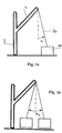
- FIGS. 1 a , 1 b show the oscillation of the load, when the cable was not aligned perpendicularly before lifting the load
- FIGS. 2 a - 2 c show an embodiment of the method of the invention, in which an imbalance of the load is compensated
- FIGS. 3 a - 3 c show an embodiment of a method of the invention, in which the yielding of the crane structure under a load is compensated
- FIG. 4 a shows an embodiment of an off-shore crane in accordance with the invention with a corresponding deflection of the cable from the plumb line due to a movement of a ship, and
- FIG. 4 b shows the graphic representation of an admissible range of cable angles.
- FIG. 5 shows another embodiment of the present invention, in which two strands of cables are provided, each with associated sensor units,
- FIG. 6 shows a torsional oscillation of the cable field including first and second strands of cables
- FIG. 7 shows a schematic diagram of the cable velocities measured during a torsional oscillation of the cable field
- FIG. 8 shows a schematic representation of the crane in accordance with the invention
- FIG. 9 shows a schematic representation of the luffing gear of the crane in accordance with the invention.
- FIG. 10 shows a schematic representation of the crane control in accordance with the invention
- FIG. 11 shows a comparison of the settings of the crane operator with a desired trajectory, which is generated by the path planning module in accordance with the invention
- FIG. 12 a shows a comparison of a desired trajectory with the actual movement of the load with respect to the load velocity
- FIG. 12 b shows a comparison of a desired trajectory with the actual movement of the load with respect to the load position
- FIG. 13 shows the velocity of the boom head as compared to the desired velocity of the load and the radial cable angle resulting from the movement
- FIG. 14 shows the time which is required for calculating the desired trajectories.
- FIG. 0 a shows an embodiment of a boom crane in accordance with the invention, here of a mobile harbour crane, as they are frequently used for performing freight handling operations in harbours.
- Such boom cranes can have load capacities of up to 140 t and a cable length of up to 80 m.
- the embodiment of the crane in accordance with the invention comprises a boom 1 , which can be swivelled up and down about a horizontal axis 2 with which it is hinged to the tower 3 .
- the tower 3 can in turn be slewed about a vertical axis, whereby the boom 1 is also slewed.
- the tower 3 is rotatably mounted on an undercarriage 6 , which can be moved by wheels 7 .
- non-illustrated positioners are provided, and for luffing up the boom 1 the actuator 4 .
- the cable 20 for lifting the load 10 is guided over a deflection pulley at the boom head, with the length of the cable 20 being adjustable by winches.
- a load suspension device is arranged on the cable 20 , e.g. a manipulator or spreader, by means of which the load 10 can be suspended.
- the load suspension device additionally includes a rotator means, by means of which the load 10 can be rotated on the load suspension device.
- the crane furthermore includes at least one first and one second strand of cables for lifting the load, with all cable strands extending from the boom tip to the load suspension device.
- the load can be moved in tangential direction by slewing the tower 3 and in radial direction by luffing up the boom 1 .
- the load 10 In vertical direction, the load 10 is moved by luffing up the boom 1 and by changing the length of the cable 20 .
- the load 10 can be rotated by the rotator unit on the load suspension device.
- a first embodiment of the mobile crane shown in FIG. 0 a now is equipped with the crane control of the invention, which includes a sensor unit for determining the cable angle relative to the direction of gravitational force.
- the sensor unit includes two sensors, by means of which the radial and tangential cable angles can each be determined relative to the direction of gravitational force.
- the crane control in accordance with the invention can not only be used in the illustrated embodiment, i.e. in a mobile harbour crane, but advantageously also in other cranes, such as e.g. ship cranes, off-shore cranes, truck cranes and crawler cranes.
- the inventive sensor unit for determining the cable angle relative to the direction of gravitational force is particularly advantageous especially in boom cranes, since known systems, as they are used for instance in cranes with a trolley merely movable in horizontal direction, and which employ measurement camera systems, cannot be used with the same.
- boom cranes such measurement camera systems would be moved together with the boom and hence merely determine the angle of the cable with respect to the boom, but not with respect to the plumb line.
- such systems would always have to be arranged directly behind the cable checkpoint on the boom head, which is, however, hardly possible with a movable cable guided over a deflection pulley on the boom head.
- the inventive sensor unit for determining the cable angle relative to the direction of gravitational force can, however, easily be arranged in a cable follower 35 , as it is shown in FIG. 0 b , and directly determines the cable angle relative to the direction of gravitational force in tangential and radial direction. A determination of the cable angle relative to the boom 1 can completely be omitted. However, if this angle of the cable relative to the boom 1 is of interest, another sensor unit could also be arranged on the boom 1 for determining the angle of the boom relative to the direction of gravitational force, in order to determine the angle between cable and boom via the difference of the respective angles of cable and boom to the direction of gravitational force.
- the cable follower 35 shown in FIG. 0 b on which the sensor unit for determining the cable angle relative to the direction of gravitational force is arranged, is mounted on the boom head 30 of the boom 1 by cardan joints 32 and 33 below the main pulley 31 .
- the cable follower 36 includes pulleys 36 , by which the cable 20 is guided, so that the cable follower 35 follows the movements of the cable 20 .
- the cardan joints 32 and 33 enable the cable follower to freely move about a horizontal and a vertical axis, but inhibit rotary movements.
- the alignment of the cable follower 35 and hence of the cable 20 relative to the direction of gravitational force can thus be determined via the sensor unit for determining the cable angle relative to the direction of gravitational force, which is arranged on the cable follower 35 .
- a gyroscope unit also is arranged on the cable follower 35 , by means of which the cable angular velocity can be measured in radial and tangential direction, for which purpose at least two correspondingly aligned gyroscopes are used.
- the data of the gyroscopes advantageously are available for load oscillation damping, which prevents the pendular movement of the load during a movement of the crane.
- corresponding cable followers 35 advantageously are associated to at least two of these cable strands, in order to be able to also consider the cable field twisting, which results from a rotation of the load suspension element out of the plane of the cable field.
- the cable followers are arranged on the respective cable strands arranged on the outside, so that a cable field twisting maximally is expressed in the difference of the cable angles.
- the actual cable angle relative to the direction of gravitational force, which corresponds to a deflection of the load from the plumb line, can be determined by averaging the values from the sensor units on the respective cable followers, the twisting of the load from the difference of the values.
- the cardan joint 32 , 33 merely serves the mechanical connection of the cable follower 35 with the boom head 30 ; the measurement of the cable angle is only effected via the sensor units integrated in the cable followers 35 , but not by determining the angle between the cable follower 35 and the boom 30 . In this way, merely the relative alignment of the cable with respect to the boom 30 could be determined, but not the cable angle of the cable 20 relative to the direction of gravitational force.
- corresponding cable followers 35 likewise are associated thereto, which are equipped with gyroscope units and thus determine the cable velocity of these cable strands.
- the determination of the cable velocities of the first and second strands of cables provides for considering the cable field twisting in the load oscillation damping for damping spherical pendular oscillations of the load and for correcting measurement errors.
- the sensor units for determining the cable angle relative to the direction of gravitational force can also be omitted, and the cable followers 35 can merely be equipped with gyroscope units.
- the inventive sensor unit for determining the cable angle relative to the direction of gravitational force on a cable follower 35
- the same could also be arranged for instance on the load suspension means, but in particular with several strands of cables, the cable followers provide an improved possibility for determining the twisting of the load.
- the crane control of the invention now is provided with the inventive sensor unit for determining a cable angle relative to the direction of gravitational force.
- FIG. 1 a shows the fundamental problem with a non-perpendicular alignment of the cable 20 .
- the cable 20 which already is connected with the still supported load 10 via a load suspension means, includes an angle ⁇ Sr relative to the direction of gravitational force indicated in phantom due to the wrong alignment of the boom 1 .
- ⁇ Sr relative to the direction of gravitational force indicated in phantom due to the wrong alignment of the boom 1 .
- the load 10 Before getting free, the load 10 can also slip or be twisted in an uncontrolled way by getting free non-uniformly.
- the deflection ⁇ Sr in radial direction is illustrated by way of example. The same problem likewise arises for a deflection of the cable 20 in tangential direction, which is caused by a wrong position of the tower 3 .
- the embodiment of the crane control of the invention therefore includes a display, which indicates the cable angle ⁇ of the cable 20 relative to the direction of gravitational force, i.e. to the plumb line.
- the display on the one hand can optically and/or acoustically indicate a perpendicular cable position and also indicate the direction in which the cable 20 is deflected from the plumb line.
- Such display thus can include e.g. display elements for a deflection to the front and to the rear and display elements for a deflection to the left or right, which indicate a deflection in radial or tangential direction.
- the horizontal deviation of the load from a zero position which corresponds to a perpendicular alignment of the cable, can also be indicated.
- a graphic display of the zero position and of the deviation of the load is conceivable, so that the absolute deflection of the load is directly indicated to the crane operator.
- the crane operator can easily align the crane at the beginning of hoisting, so that the cable 20 is perpendicularly arranged above the load 10 .
- the correct perpendicular cable position then can be indicated e.g. acoustically by a signal tone.
- a function for automatically aligning the cable in perpendicular direction is provided.
- the crane is automatically aligned upon fastening the load suspension means to the load such that the cable is perpendicular.
- this automatic function advantageously is connected e.g. with a cable force measuring means, which switches off the automatic operation in the case of errors.
- the cable field twisting can also be determined via a plurality of sensor units.
- This cable field twisting corresponds to the twisting of the load suspension means, e.g. a spreader, and would lead to a rotation of the load when lifting the load.
- the twisting of the cable field also is indicated advantageously, possibly beside the cable angle relative to the direction of gravitational force or the horizontal deviation of the load.
- the load suspension means includes a rotor means
- the cable field twisting thereby can be set to 0 before hoisting, in order to prevent a rotation of the load 10 when lifting the same.
- a function for automatically aligning the rotor means can also be provided advantageously in a further embodiment.
- the embodiment of the crane control of the invention includes a warning means beside the display, which warns the crane operator by an optical and/or acoustic signal when the admissible range of values for a deviation resulting from the measured cable angle, in particular for the cable angle relative to the gravitational force, is exceeded.
- a warning means beside the display which warns the crane operator by an optical and/or acoustic signal when the admissible range of values for a deviation resulting from the measured cable angle, in particular for the cable angle relative to the gravitational force, is exceeded.
- an automatic protection means e.g. in the form of an overload protection, which automatically intervenes in the control of the crane when the admissible range of values is exceeded.
- the automatic overload protection stops the movement of the crane, in order to prevent an overload.
- the overload protection can be integrated in the load moment limitation of the crane, which thus protects the crane against being loaded by too large a cable angle.
- FIGS. 2 and 3 now, two situations are shown, in which the cable 20 initially is aligned perpendicularly, but is moved away from the plumb line when the load 10 is lifted.
- the deviation of the cable angle from the plumb line therefore is determined while lifting the load 10 .
- the crane operator checks the cable angle or the horizontal deviation on the display and readjusts the crane during the hoisting operation, in order to again compensate the deviation of the cable angle from the plumb line due to the imbalance of the load.
- the imbalance of the load is determined on the basis of the deviation of the cable angle from the plumb line and indicated, so that the crane operator can react in a better way.
- the load suspension means includes a device for the in particular linear movement of the load 10 relative to the load suspension point 25 , by means of which the center of gravity 26 of the load can be arranged below the load suspension point 25 without tilting the load 10 .
- the load suspension means e.g. a spreader, includes e.g. a longitudinal displacement of the load suspension point 25 relative to the load, e.g. a container.
- the crane operator can shift the load suspension point relative to the load, until the cable again is aligned perpendicularly.
- the imbalance of the load can be determined and indicated by means of the deviation of the cable angle from the plumb line, so that the crane operator can perform the actuation of the longitudinal adjustment of the spreader by means of this indication.
- An automatic adjustment of the spreader is also conceivable.
- Such adjustment of the spreader by means of the deviation of the cable angle from the plumb line is particularly advantageous, as tilting of the container in particular when being loaded in a ship can lead to jamming of the containers, so that loading can be impeded considerably.
- FIGS. 3 a to 3 c now illustrate a further effect which can cause a deviation of the cable angle from the plumb line when lifting the load.
- the cable 20 still is aligned perpendicularly before the beginning of the hoisting operation. Since the center of gravity 26 of the load is located below the load suspension point 25 , i.e. the load has no imbalance, the load suspension point 25 is not shifted in this case when lifting the load 10 .
- the crane structure yields due to the load applied when lifting the load, with tower 3 and boom 1 being slightly bent forward in this case.
- the boom tip 30 over which runs the cable 20 , is moved relative to the load suspension point 25 , so that a deviation of the cable angle from the plumb line results from the yielding of the crane structure.
- this deviation is compensated by the crane operator by means of the indication of the cable angle when lifting the load. It is also possible to determine the deviation of the cable angle from the plumb line due to the crane structure yielding under the load, which can then be indicated to facilitate the work of the crane operator.
- an automatic tracking of the crane is possible for the perpendicular alignment on the basis of the data of the sensor unit for determining the cable angle relative to the direction of gravitational force. When the cable angle again is aligned perpendicularly, the load can be lifted without oscillations, as shown in FIG. 3 c.
- FIG. 4 a shows another embodiment of the crane of the invention.
- This is an off-shore crane, which is arranged on an off-shore platform 50 and is used e.g. for loading a load 10 from a ship 60 onto the platform 50 . Since the ship 60 can move relative to the platform 50 , the cable angle of the cable 20 relative to the plumb line can also be changed without a movement of the crane due to a movement of the ship.
- an overload function is provided in one embodiment of the crane control of the invention, which possibly can be used beside the above-described warning and safety functions.
- countermeasures are taken when the cable angle exceeds a maximum admissible range.
- the movement of the crane can partly be enabled, in that for instance the cable 20 is released or the stewing movement of the tower 3 . This release is effected in a controlled way with a certain counterforce, in order to avoid sudden jerks.
- the admissible range 70 for the cable angle in X and Y direction is shown in hatched lines e.g. in FIG. 4 b . If the cable angle exceeds this admissible range 70 , either the inventive warning function or one of the inventive overload functions will be initiated.
- FIG. 4 b shows a display element for indicating a deviation from a perpendicular position of the cable, with an admissible range 70 for the cable angle and for the horizontal deviation in X and Y direction, i.e. in radial and tangential direction.
- the indication of the cable angle here is effected graphically, e.g. in that the cable angle is represented as a dot in the diagram shown in FIG. 4 b .
- the horizontal deviation of the load from the zero position located in the middle can also be illustrated, i.e. the distance of the load from the position in which it would be with the same crane position, but perpendicular cable. The crane operator thus can directly see the absolute deflection of the load and estimate more easily how far the crane must be moved for a correct alignment of the cable.
- the crane includes at least one first and one second strand of cables, which connect the load suspension means with the boom tip.
- this provides an improved damping of the spherical oscillations of the load by the crane control in accordance with the invention.
- the gyroscope signals include an offset and also detect disturbing influences, such as cable harmonics, observer circuits are used for integrating the velocities to obtain the cable angles.
- the gyroscopes are attached to the cable below the boom tip by means of a mechanical construction.
- two gyroscopes are necessary, which are arranged in tangential and radial direction.
- FIG. 0 b shows a first cable follower 35 , on which the first sensor unit associated to the first strand of cables is arranged in the embodiment shown here.
- the first cable follower is mounted on the boom head 30 of the boom 1 by cardan joints 32 and 33 below a first pulley 31 , over which the first cable strand 20 is guided.
- the cable follower 35 includes pulleys 35 , by which the first cable strand 20 is guided, so that the cable follower 35 follows the movements of the cable strand 20 .
- the cardan joints 32 and 33 allow the cable follower to freely move about a horizontal and a vertical axis, but inhibit rotary movements.
- the radial and tangential angular velocity of the first cable follower 35 and hence of the first cable strand 20 thus can be determined via the first sensor unit arranged on the cable follower 35 , which is configured as a gyroscope unit.
- a second cable follower with a second sensor unit, which is associated to a second strand of cables, is constructed analogous to the first cable follower and connected with the boom tip. The second cable follower correspondingly measures the angular velocity of the second strand of cables.
- each gyroscope sensor on both cable followers each is ⁇ einbau
- ⁇ dot over ( ⁇ ) ⁇ D is the slewing speed of the crane
- ⁇ dot over ( ⁇ ) ⁇ t/r mess is the tangential or radial angular velocity
- ⁇ dot over ( ⁇ ) ⁇ t/r komp is the resulting compensated gyroscope signal.
- the compensated measurement signals are integrated by means of an observer circuit to obtain the cable angles free from offset. After such processing, the cable angles now are available for both cable followers in tangential and radial direction.
- the expansion of the measurement concept by the second cable follower leads to two essential advantages as compared to the variant with only one cable follower or the variant with the gyroscope sensors in the hook.
- the first advantage is the redundancy of the measurement of load oscillation.
- the angular velocity still is detected by the sensor of the other holder.
- the basic function of the crane control (oscillation damping and sequence of trajectories) can thus be ensured.
- a sensor error still can be detected when a threshold value is exceeded.
- the crane thus can immediately be brought into a safe condition.
- the second advantage is the possibility for compensating the torsional oscillation of the load. As shown by equation 0.2, the mean value of the angle signals of the two cable followers is calculated in the corresponding direction.
- the cable angle in tangential direction ⁇ t thus is calculated from the mean value of the observed angle signals of the holder 41 ⁇ t beob H1 and of the holder 42 ⁇ t beob H2 .
- the same is true for the cable angle in radial direction symbolized by the index r.
- the gyroscopes on the cable followers 41 and 42 exactly measure an opposite parasitic oscillation both in tangential and in radial direction. By forming an average, the influence of the torsional oscillation thus can be eliminated.
- the inventive control of load oscillation damping in which the data generated by the two gyroscope units are included, will now be illustrated in detail below.
- the dynamics of the boom movement is characterized by some predominant non-linear effects.
- the use of a linear control unit would therefore lead to great errors in the tracking of trajectories and to an insufficient damping of load oscillation.
- the present invention utilizes a non-linear control procedure, which is based on the inversion of a simplified non-linear model.
- This control procedure for the luffing movement of a boom crane allows a non-slewing load movement in radial direction.
- the resulting crane control in accordance with the invention shows a high accuracy of the tracking of trajectories and a good damping of load oscillation. Measurement results are submitted to validate the good performance of the non-linear control unit for the tracking of trajectories.
- Boom cranes such as the LIEBHERR mobile harbour crane LHM (see FIG. 1 ), are used for efficiently handling loading processes in harbours.
- Boom cranes of this type are characterized by a load capacity of up to 140 tons, a maximum outreach of 48 meters, and a cable length of up to 80 meters.
- a spherical load oscillation is induced. Such load oscillation must be avoided for safety and performance reasons.
- such mobile harbour crane consists of a mobile platform 6 , on which a tower 3 is mounted.
- the tower 3 can be slewed about a vertical axis, with its position being described by the angle ⁇ D .
- a boom 1 is pivotally mounted, which can be luffed by the actuator 4 , with its position being described by the angle ⁇ A .
- the load 10 is suspended from the head of the boom 1 on a cable of the length l S and can oscillate under the angle ⁇ Sr .
- the following embodiment of the present invention utilizes a flatness-based control approach for the radial direction of a boom crane.
- the approach is based on a simplified non-linear model of the crane.
- the law of the linearizing control can be formulated.
- the zero dynamics of the non-simplified non-linear control loop ensures a sufficient damping property.
- the non-linear dynamic model In consideration of the control objects of preventing load oscillation and of tracking a reference trajectory in radial direction, the non-linear dynamic model must be derived for the luffing movement.
- the first part of the model is obtained by
- FIG. 8 is a schematic representation of the luffing movement, wherein ⁇ Sr is the radial cable angle, ⁇ umlaut over ( ⁇ ) ⁇ Sr the radial angular acceleration, l S the cable length, ⁇ umlaut over (r) ⁇ A the acceleration of the boom end, and g the gravitational constant.
- the second part of the dynamic model describes the kinematics and dynamics of the actuator for the radial direction. Assuming that the hydraulic cylinder exhibits a first-order behavior, the differential equation of the movement is obtained as follows:
- ⁇ umlaut over (z) ⁇ zyl and ⁇ zyl are the cylinder acceleration and the velocity
- T W is the time constant
- a zyl is the cross-sectional area of the cylinder
- u W is the input voltage of the servo valve
- K VW is the proportional constant of flow rate to u W .
- FIG. 9 shows a schematic representation of the kinematics of the actuator with the geometric constants d a , d b , ⁇ 1 , ⁇ 2 .
- r A ⁇ ( z zyl ) l A ⁇ cos ( ⁇ A ⁇ ⁇ 0 - arc ⁇ ⁇ cos ( d a 2 + d b 2 - z zyl 2 2 ⁇ d a ⁇ d b ) ) ( 3 ) is differentiated.
- ⁇ dot over (r) ⁇ A ⁇ l A sin( ⁇ A ) K Wz1 ( ⁇ A ) ⁇ zyl (4)
- ⁇ umlaut over (r) ⁇ A ⁇ l A sin( ⁇ A ) K Wz1 ( ⁇ A ) ⁇ umlaut over (z) ⁇ zyl ⁇ K Wz3 ( ⁇ A ) ⁇ zyl 2
- K Wz1 and K Wz3 describe the dependence on the geometric constants d a , d b , ⁇ 1 , ⁇ 2 and the luffing angle ⁇ A (see FIG. 9 ).
- l A is the length of the boom.
- r ⁇ A - K Wz ⁇ ⁇ 3 l A 2 ⁇ sin 2 ⁇ ( ⁇ A ) ⁇ K Wz ⁇ ⁇ 1 2 ⁇ a ⁇ r .
- a 2 1 T W ⁇ b ⁇ r .
- the operator L f l represents the Lie derivative along the vector field f l or L g l along the vector field g l .
- y l is a non-flat output.
- an error feedback is derived between the reference trajectory and the derivatives of the output y*.
- FIG. 10 shows the resulting structure of the linearized and stabilized system.
- the tracking control unit is based on the simplified load oscillation ODE ( 8 ) and not on the load oscillation ODE ( 1 ). Furthermore, the fictitious output y l * is used for the design of the control unit. The resulting internal dynamics is shown in DE 10 2006 048 988, which is not yet published and whose contents form part of the present application.
- the problem of trajectory generation is formulated as a restricted optimal control problem of the open chain for the linearized system with status feedback. Due to the relevant calculation time for the solution of the optimal control problem, the model-predictive trajectory generation is performed with a non-negligeable scan time. By means of the numerical solution method itself, a discretization of the time axis is introduced. For the sake of simplicity, however, the optimal control problem was continually represented in continuous time.
- the state variables x lin are the states of the integrator chain which is obtained from the linearized system, consisting of flatness-based controller (equation (14)) and non-linear system (equation (6)), and the states of the integrator chain for the reference trajectory. Additional states are introduced, in order to obtain a smooth input v.
- the initial state x lin,0 is derived from the states of these integrators, the current system output and its derivatives.
- the outputs y lin of the linear system (equation (15)) are variables which correspond to the flat output y* (equation (12)) and its first and second derivatives. These variables are the position, velocity and acceleration of the load in radial direction.
- J c 1 2 ⁇ ⁇ t 0 t f ⁇ ( ( y lin - w ) T ⁇ Q ⁇ ( y lin - w ) + r ⁇ u . lin 2 ) ⁇ ⁇ d t ( 16 ) on the one hand considers the square deviation of the predicted outputs y lin from the reference prediction w(t) thereof and on the other hand the square change of the input variable u lin .
- the optimization horizon t f -t 0 , the symmetrical, positive semi-definite weighting matrix Q and the weighting coefficient r>0 are essential adjustment parameters for the model-predictive trajectory generation.
- the optimization horizon t f -t 0 should capture the essential dynamic behavior of the process/system. This is defined by the duration of the period of load oscillation (up to 18 seconds for the crane observed). Experiments have shown that 10 seconds are sufficient for the optimization horizon.
- the reference prediction w(t) for the position, velocity and acceleration of the load is generated from the hand lever signals of the crane operator (desired velocities).
- the prediction considers reductions in velocity, when the load approaches the limits of the working range.
- the model-predictive trajectory generation considers restrictions for the process variables as restrictions of the optimal control problem. u lin,min ⁇ u lin ⁇ u lin,max (17) y lin,min ⁇ y lin ⁇ y lin,max
- Equation (19) probably cause unsolvable optimal control problems under non-nominal conditions, such as model uncertainties or measurement noise, particularly for short optimization horizons.
- equation restriction (19) is approximated as a square penalty term with symmetrical, positive definite weighting matrix Q , which extends the original power functional as follows:
- x lin k , u k and y lin k designate the values of the corresponding variables in the discretization points t k .
- the matrixes and vectors A k , b k and C k are obtained by solving the transition equation in [t k ,t k+1 ] from A, b and C.
- the power functional (equation (20)) and the restrictions (equations (17)(18)) likewise are discretized correspondingly.
- the representation shows that the initial incrementation is determined by the clock rate of trajectory generation and then is increasing linearly within the prediction horizon.
- FIG. 11 shows the velocity of the load, once as specified by the crane operator by means of an input element, and once as specified via the inventive path planning module by means of optimal control as a desired trajectory.
- the restrictions of the system are not considered here, so that the upper limit for the velocity of the load depends on the radial load position, as the geometries of the boom and of the luffing cylinder permit different maximum velocities with different boom positions. For the maximum acceleration, however, a constant restriction is specified.
- this desired trajectory now is compared with the measured velocity of the load.
- the control in accordance with the invention follows the desired trajectory, wherein the path planning module compensates uncertainties in the model by a model-based path planning. This results in a fast and damped movement of the load without any appreciable overswings.
- FIG. 12 b shows the corresponding trajectory of the load position.
- the inventive control is damping the spherical oscillations of the load by corresponding compensating movements of the boom during and at the end of each maneuver. This is shown in FIG. 13 , in which the countermovements performed by the boom tip are shown, which counteract the oscillation of the load.
- the cable angle can be limited to less than 3°.
- the calculation time required for the online calculation of the optimal solution problem in the path planning module is shown in FIG. 14 .
- What is decisive for this extremely short response of the path planning to the specifications of the crane operator on the one hand is the fast solvability due to the subsequent linear path of non-linear control and non-linear crane system, and the increasing length of the intervals between the checkpoints of the prediction within the prediction horizon.
Landscapes
- Engineering & Computer Science (AREA)
- Mechanical Engineering (AREA)
- Automation & Control Theory (AREA)
- Control And Safety Of Cranes (AREA)
- Jib Cranes (AREA)
Abstract
Description
{dot over (φ)}t/r komp={dot over (φ)}t/r mess−sin(φeinbau){dot over (φ)}D (0.1)
-
- neglecting mass and elasticity of the cable
- assuming that load is a point mass
- neglecting the centripetal and Coriolis terms
is differentiated.
{dot over (r)} A =−l A sin(φA)K Wz1(φA)ż zyl (4)
{umlaut over (r)} A =−l A sin(φA)K Wz1(φA){umlaut over (z)} zyl −K Wz3(φA)ż zyl 2
{dot over (x)} l =f l( x l)+ g l( x l)·u l (6)
y l =h l( x l)
the equations (1) and (6) are used. As a result, the status x=[rA {dot over (r)}A φSr {dot over (φ)}Sr]T used as an input and the radial position of the load y=rLA provided as an output lead to:
2. Non-Linear Control Approach
L g
L g
y l *=h l*( x l)=x l,1 +l s x l,3 (11)
a relative degree of r=2 is obtained. Since the order of the simplified non-linear model is 4, yl is a non-flat output. But with a new output
y*=h*( x )=x l +l s x 3 (12)
a relative degree of r=4 is obtained. Assuming that only small radial cable angles occur, the difference between the real output yl and the flat output yl* can be neglected. This simplification is chosen, in order to minimize the calculation time for the generation of trajectories described in
2.2 Exact Linearization
{dot over (x)} lin =A lin x lin +b lin u lin , x lin(t 0)=x lin,0 (15)
ylin=Clinxlin
on the one hand considers the square deviation of the predicted outputs ylin from the reference prediction w(t) thereof and on the other hand the square change of the input variable ulin. The optimization horizon tf-t0, the symmetrical, positive semi-definite weighting matrix Q and the weighting coefficient r>0 are essential adjustment parameters for the model-predictive trajectory generation.
ulin,min≦ulin≦ulin,max (17)
ylin,min≦ylin≦ylin,max
{dot over (u)}lin,min≦{dot over (u)}lin≦{dot over (u)}lin,max (18)
x lin(t f)=x lin,f(w(t f)) (19)
t0=t0≦t1≦ . . . ≦tK=tf
x lin k+1 A k x lin k +b k u lin k , k=0, . . . , K−1 (21)
xlin 0=xlin,0
ylin k=Clin kxlin k, k=0, . . . , K
Claims (40)
Applications Claiming Priority (6)
| Application Number | Priority Date | Filing Date | Title |
|---|---|---|---|
| DE102007023027.5 | 2007-05-16 | ||
| DE102007023027 | 2007-05-16 | ||
| DE102007023027 | 2007-05-16 | ||
| DE102007039408.1 | 2007-08-21 | ||
| DE102007039408A DE102007039408A1 (en) | 2007-05-16 | 2007-08-21 | Crane control system for crane with cable for load lifting by controlling signal tower of crane, has sensor unit for determining cable angle relative to gravitational force |
| DE102007039408 | 2007-08-21 |
Publications (2)
| Publication Number | Publication Date |
|---|---|
| US20090008351A1 US20090008351A1 (en) | 2009-01-08 |
| US8025167B2 true US8025167B2 (en) | 2011-09-27 |
Family
ID=39868919
Family Applications (1)
| Application Number | Title | Priority Date | Filing Date |
|---|---|---|---|
| US12/152,717 Active US8025167B2 (en) | 2007-05-16 | 2008-05-16 | Crane control, crane and method |
Country Status (4)
| Country | Link |
|---|---|
| US (1) | US8025167B2 (en) |
| EP (1) | EP2502871B1 (en) |
| DE (2) | DE102007039408A1 (en) |
| ES (2) | ES2531374T5 (en) |
Cited By (31)
| Publication number | Priority date | Publication date | Assignee | Title |
|---|---|---|---|---|
| US20110218714A1 (en) * | 2008-12-15 | 2011-09-08 | Scheider Toshiba Inverter Europe Sas | Device for controlling the movement of a load suspended from a crane |
| US8195368B1 (en) * | 2008-11-07 | 2012-06-05 | The United States Of America As Represented By The Secretary Of The Navy | Coordinated control of two shipboard cranes for cargo transfer with ship motion compensation |
| US8265854B2 (en) | 2008-07-17 | 2012-09-11 | Honeywell International Inc. | Configurable automotive controller |
| US8360040B2 (en) | 2005-08-18 | 2013-01-29 | Honeywell International Inc. | Engine controller |
| CN102910533A (en) * | 2012-10-26 | 2013-02-06 | 北京机械设备研究所 | Spatial angle measuring method based on crane |
| US8504175B2 (en) | 2010-06-02 | 2013-08-06 | Honeywell International Inc. | Using model predictive control to optimize variable trajectories and system control |
| US20130245816A1 (en) * | 2012-03-09 | 2013-09-19 | Liebherr-Werk Nenzing Gmbh | Crane controller with cable force mode |
| US8620461B2 (en) | 2009-09-24 | 2013-12-31 | Honeywell International, Inc. | Method and system for updating tuning parameters of a controller |
| US9238570B2 (en) | 2011-07-05 | 2016-01-19 | Trimble Navigation Limited | Crane maneuvering assistance |
| US9556006B2 (en) | 2014-06-02 | 2017-01-31 | Liebherr-Werk Nenzing Gmbh | Method for controlling the orientation of a crane load and a boom crane |
| US9650934B2 (en) | 2011-11-04 | 2017-05-16 | Honeywell spol.s.r.o. | Engine and aftertreatment optimization system |
| US9677493B2 (en) | 2011-09-19 | 2017-06-13 | Honeywell Spol, S.R.O. | Coordinated engine and emissions control system |
| US10036338B2 (en) | 2016-04-26 | 2018-07-31 | Honeywell International Inc. | Condition-based powertrain control system |
| US10124750B2 (en) | 2016-04-26 | 2018-11-13 | Honeywell International Inc. | Vehicle security module system |
| US10235479B2 (en) | 2015-05-06 | 2019-03-19 | Garrett Transportation I Inc. | Identification approach for internal combustion engine mean value models |
| US20190119078A1 (en) * | 2016-04-11 | 2019-04-25 | Liebherr-Components Biberach Gmbh | Crane, and Method for Controlling Such a Crane |
| US10272779B2 (en) | 2015-08-05 | 2019-04-30 | Garrett Transportation I Inc. | System and approach for dynamic vehicle speed optimization |
| US10309287B2 (en) | 2016-11-29 | 2019-06-04 | Garrett Transportation I Inc. | Inferential sensor |
| US10415492B2 (en) | 2016-01-29 | 2019-09-17 | Garrett Transportation I Inc. | Engine system with inferential sensor |
| US10423131B2 (en) | 2015-07-31 | 2019-09-24 | Garrett Transportation I Inc. | Quadratic program solver for MPC using variable ordering |
| US10503128B2 (en) | 2015-01-28 | 2019-12-10 | Garrett Transportation I Inc. | Approach and system for handling constraints for measured disturbances with uncertain preview |
| US10621291B2 (en) | 2015-02-16 | 2020-04-14 | Garrett Transportation I Inc. | Approach for aftertreatment system modeling and model identification |
| US11021347B2 (en) * | 2015-10-08 | 2021-06-01 | Verton Holdings Pty Ltd | Materials management systems and methods |
| US11057213B2 (en) | 2017-10-13 | 2021-07-06 | Garrett Transportation I, Inc. | Authentication system for electronic control unit on a bus |
| US11111115B2 (en) | 2017-03-02 | 2021-09-07 | Maniitowoc Crane Companies, LLC | Wear pad with insert for telescoping boom assembly |
| US11156180B2 (en) | 2011-11-04 | 2021-10-26 | Garrett Transportation I, Inc. | Integrated optimization and control of an engine and aftertreatment system |
| US11447372B2 (en) * | 2017-07-03 | 2022-09-20 | Liebherr-Werk Biberach Gmbh | Crane and method for controlling such a crane |
| US11618566B1 (en) * | 2019-04-12 | 2023-04-04 | Vita Inclinata Technologies, Inc. | State information and telemetry for suspended load control equipment apparatus, system, and method |
| US11834305B1 (en) * | 2019-04-12 | 2023-12-05 | Vita Inclinata Ip Holdings Llc | Apparatus, system, and method to control torque or lateral thrust applied to a load suspended on a suspension cable |
| US12099337B1 (en) * | 2019-12-06 | 2024-09-24 | Vita Inclinata Ip Holdings Llc | Control moment gyroscope hoist stabilization system, method, and apparatus |
| US12358763B2 (en) | 2018-11-07 | 2025-07-15 | Manitowoc Crane Companies, Llc | System for determining crane status using optical and/or electromagnetic sensors |
Families Citing this family (62)
| Publication number | Priority date | Publication date | Assignee | Title |
|---|---|---|---|---|
| US7467614B2 (en) | 2004-12-29 | 2008-12-23 | Honeywell International Inc. | Pedal position and/or pedal change rate for use in control of an engine |
| DE102008024513B4 (en) * | 2008-05-21 | 2017-08-24 | Liebherr-Werk Nenzing Gmbh | Crane control with active coast sequence |
| DE102009032269A1 (en) | 2009-07-08 | 2011-01-13 | Liebherr-Werk Nenzing Gmbh | Crane control for controlling a hoist of a crane |
| DE102009032270A1 (en) | 2009-07-08 | 2011-01-13 | Liebherr-Werk Nenzing Gmbh | Method for controlling a drive of a crane |
| DE102009032267A1 (en) * | 2009-07-08 | 2011-01-13 | Liebherr-Werk Nenzing Gmbh, Nenzing | Crane for handling a load suspended on a load rope |
| CN101659379B (en) * | 2009-08-27 | 2012-02-08 | 三一汽车制造有限公司 | Method, system and device for controlling deviation of hanging hook |
| DE102010027771B4 (en) * | 2010-04-15 | 2014-05-22 | Airbus Operations Gmbh | Device and method for controlling or regulating a control route |
| CA2834235C (en) | 2011-04-29 | 2017-05-09 | Harnischfeger Technologies, Inc. | Controlling a digging operation of an industrial machine |
| CN102249151B (en) * | 2011-05-20 | 2013-06-12 | 林汉丁 | Laser display and supervision arrangement for declination angle of crane lift hook |
| DE102011108284A1 (en) * | 2011-07-21 | 2013-01-24 | Liebherr-Werk Ehingen Gmbh | Crane control and crane |
| EP2562125B1 (en) * | 2011-08-26 | 2014-01-22 | Liebherr-Werk Nenzing GmbH | Crane control apparatus |
| CN102431897B (en) * | 2011-11-25 | 2014-04-30 | 林汉丁 | Crane lifting verticality deviation measuring and displaying device and lifting method |
| DE102012004802A1 (en) * | 2012-03-09 | 2013-09-12 | Liebherr-Werk Nenzing Gmbh | Crane control with distribution of a kinematically limited size of the hoist |
| FI20135085A7 (en) * | 2013-01-29 | 2014-07-30 | John Deere Forestry Oy | Method and system for controlling the boom of a work machine using tip control |
| ES2676452T3 (en) * | 2013-07-05 | 2018-07-19 | Liebherr-Werk Nenzing Gmbh | Crane controller |
| DE102013012019B4 (en) | 2013-07-19 | 2019-10-24 | Tadano Faun Gmbh | Crane, in particular mobile crane |
| DE102013219279A1 (en) | 2013-09-25 | 2015-03-26 | Schaeffler Technologies Gmbh & Co. Kg | Load-bearing damper and lifting device for suspended loads |
| ES2534957B1 (en) * | 2013-09-30 | 2016-02-02 | Yoel Orlando IZQUIERDO HERNÁNDEZ | SYSTEM FOR REPORTING THE CRANK OF LIFTING CRANES AND APPLIANCES WITH RESPECT TO LOAD. |
| WO2016019289A1 (en) * | 2014-07-31 | 2016-02-04 | Par Systems, Inc. | Crane motion control |
| CN104340875B (en) * | 2014-10-09 | 2016-05-11 | 中联重科股份有限公司 | Crane boom posture monitoring control system, method and device and crane |
| EP3056464A1 (en) * | 2015-02-11 | 2016-08-17 | Siemens Aktiengesellschaft | Automated crane control taking into account load and location dependent measurement errors |
| US20160244302A1 (en) * | 2015-02-23 | 2016-08-25 | Transocean Sedco Forex Ventures Limited | Marine motion compensated draw-works real-time performance monitoring and prediction |
| PL3362400T3 (en) * | 2015-10-16 | 2020-03-31 | Palfinger Ag | Arrangement of a control device and a mobile control module |
| DE102016001684A1 (en) * | 2016-02-12 | 2017-08-17 | Liebherr-Werk Biberach Gmbh | Method for monitoring at least one crane |
| DE102016004266A1 (en) | 2016-04-08 | 2017-10-12 | Liebherr-Werk Biberach Gmbh | Construction machine, in particular crane, and method for its control |
| DE102016004249A1 (en) | 2016-04-08 | 2017-10-12 | Liebherr-Components Biberach Gmbh | crane |
| CN106185627B (en) * | 2016-07-06 | 2020-09-08 | 林汉丁 | Lifting hook deflection angle monitoring device, vertical hoisting monitoring device and mobile crane |
| DE102017125715A1 (en) | 2016-11-09 | 2018-05-09 | Liebherr-Werk Biberach Gmbh | Device for compensation of diagonal tension in cranes |
| DE202016008626U1 (en) * | 2016-11-15 | 2018-09-14 | Josef Morosin | Arrangement with a crane |
| FR3071489A1 (en) * | 2017-09-28 | 2019-03-29 | Manitowoc Crane Group France | METHOD FOR SECURING A CRANE ARROW CRANE AND ASSOCIATED CRANE |
| EP3461783B1 (en) * | 2017-09-29 | 2019-11-13 | B&R Industrial Automation GmbH | Lifting device and method for controlling a lifting device |
| US10828790B2 (en) * | 2017-11-16 | 2020-11-10 | Google Llc | Component feature detector for robotic systems |
| NL2021043B1 (en) | 2018-06-01 | 2019-12-10 | Itrec Bv | Offshore wind turbine installation vessel and a crane for providing such a vessel and method for upending a monopile |
| KR102120650B1 (en) * | 2018-04-25 | 2020-06-26 | 주식회사 만도 | The device of avoiding vehicle collision and control method thereof |
| US10654692B2 (en) * | 2018-05-04 | 2020-05-19 | Rowan Companies, Inc. | System and method for remote crane operations on offshore unit |
| EP3566998B1 (en) * | 2018-05-11 | 2023-08-23 | ABB Schweiz AG | Control of overhead cranes |
| DE102018005068A1 (en) | 2018-06-26 | 2020-01-02 | Liebherr-Components Biberach Gmbh | Crane and method for controlling such a crane |
| JP7172243B2 (en) * | 2018-07-25 | 2022-11-16 | 株式会社タダノ | Cranes and crane control systems |
| JP7134087B2 (en) * | 2018-12-27 | 2022-09-09 | コベルコ建機株式会社 | Load deflection angle measuring device for cranes |
| JP7322901B2 (en) * | 2019-02-14 | 2023-08-08 | 株式会社タダノ | Ground-breaking control device and mobile crane |
| JP7151532B2 (en) * | 2019-02-14 | 2022-10-12 | 株式会社タダノ | Crane and crane path generation system |
| JP7484731B2 (en) * | 2019-02-14 | 2024-05-16 | 株式会社タダノ | Ground lift control device and crane |
| DE202019102393U1 (en) | 2019-03-08 | 2020-06-09 | Liebherr-Werk Biberach Gmbh | Crane and device for its control |
| JP7247703B2 (en) * | 2019-03-27 | 2023-03-29 | 株式会社タダノ | Crane control method and crane |
| DE102019109448B4 (en) | 2019-04-10 | 2022-09-08 | Josef Morosin | Arrangement with a crane |
| CN112079252A (en) * | 2019-06-14 | 2020-12-15 | 湖南釜晟智能科技有限责任公司 | Anti-swing control system for overhead travelling crane hoisted object |
| DE102019122796A1 (en) | 2019-08-26 | 2021-03-04 | Liebherr-Werk Biberach Gmbh | Crane and method of controlling such a crane |
| DE102020112227A1 (en) * | 2019-11-22 | 2021-05-27 | Liebherr-Werk Biberach Gmbh | Construction and / or material handling machine |
| CN111348544A (en) * | 2020-04-16 | 2020-06-30 | 林汉丁 | Real-time lifting hook deflection angle monitoring device capable of displaying lifting weight and crane |
| JP7445510B2 (en) * | 2020-05-01 | 2024-03-07 | 株式会社Ihi | Shake angle detection device |
| CN111573504A (en) * | 2020-05-20 | 2020-08-25 | 林汉丁 | A single-machine hoisting and hoisting synergistic hoisting device and mobile crane |
| DE102020120699A1 (en) * | 2020-08-05 | 2022-02-10 | Konecranes Global Corporation | Slewing jib crane with a camera and methods for reducing load sway during crane operation |
| DE102020126504A1 (en) | 2020-10-09 | 2022-04-14 | Liebherr-Werk Biberach Gmbh | Hoist such as a crane and method and device for controlling such a hoist |
| CN112324793B (en) * | 2020-11-20 | 2021-12-24 | 安徽博微长安电子有限公司 | Telescopic wind-resistant pull rod mechanism |
| CN113086862A (en) * | 2021-04-09 | 2021-07-09 | 国网山东省电力公司安丘市供电公司 | Electric element conveyor |
| WO2023276970A1 (en) * | 2021-06-30 | 2023-01-05 | 株式会社キトー | Transport system and method for controlling transport system |
| USD1019048S1 (en) * | 2021-07-01 | 2024-03-19 | Liebherr-Werk Biberach Gmbh | Crane |
| CN113465567B (en) * | 2021-08-11 | 2022-05-31 | 广东皓耘科技有限公司 | Cable parameter detection device and cable parameter detection method |
| DE102021130785A1 (en) | 2021-11-24 | 2023-05-25 | Liebherr-Werk Biberach Gmbh | crane |
| CN115291527B (en) * | 2022-09-30 | 2022-12-20 | 成都航天万欣科技有限公司 | Follow-up control method, system, equipment and storage medium |
| DE102023109735A1 (en) * | 2023-04-18 | 2024-10-24 | Liebherr-MCCtec Rostock GmbH | crane |
| DE102023109701A1 (en) * | 2023-04-18 | 2024-10-24 | Liebherr-Werk Nenzing Gmbh | Method, system and computer program product for moving a load by means of a plurality of cranes |
Citations (15)
| Publication number | Priority date | Publication date | Assignee | Title |
|---|---|---|---|---|
| US3904156A (en) * | 1974-07-11 | 1975-09-09 | Us Army | External load stabilization apparatus |
| US4471877A (en) * | 1982-09-01 | 1984-09-18 | Whitley Charles C | Crane sensor to detect out of plumb lift cable |
| DD275035A1 (en) | 1988-08-29 | 1990-01-10 | Univ Dresden Tech | DEVICE FOR MEASURING THE PENDULUM ANGLE |
| US4932541A (en) * | 1989-04-24 | 1990-06-12 | Calspan Corporation | Stabilized shipboard crane |
| DE4032332A1 (en) | 1990-10-09 | 1992-04-16 | Mannesmann Ag | MEASURING DEVICE FOR DETECTING THE PENDULUM ANGLE |
| JPH04223993A (en) | 1990-09-21 | 1992-08-13 | Kobe Steel Ltd | Rope swinging angle detecting device of crane |
| US5667186A (en) * | 1993-06-21 | 1997-09-16 | Carl-Zeiss-Stiftung | Stand for mounting various loads |
| US5729339A (en) * | 1993-09-02 | 1998-03-17 | Korea Atomic Energy Research Institute | Swing angle measuring apparatus for swing free operation of crane |
| DE19842436A1 (en) | 1998-09-16 | 2000-03-30 | Grove Us Llc Shady Grove | Method and device for compensating for the deformation of a crane boom when lifting and lowering loads |
| DE10042699A1 (en) | 2000-08-31 | 2002-04-04 | Elektroschaltanlagen Gmbh | Crane load swing angle sensor uses inclinometer is cheap allows good control |
| US6496765B1 (en) * | 2000-06-28 | 2002-12-17 | Sandia Corporation | Control system and method for payload control in mobile platform cranes |
| US6496766B1 (en) * | 1999-03-01 | 2002-12-17 | North Carolina State University | Crane monitoring and data retrieval systems and method |
| EP1326798A1 (en) | 2000-10-19 | 2003-07-16 | Liebherr-Werk Nenzing GmbH | Crane or digger for swinging a load hanging on a support cable with damping of load oscillations |
| US6826452B1 (en) * | 2002-03-29 | 2004-11-30 | The Penn State Research Foundation | Cable array robot for material handling |
| US20080019815A1 (en) * | 2005-10-05 | 2008-01-24 | Oshkosh Truck Corporation | System for monitoring load and angle for mobile lift device |
Family Cites Families (6)
| Publication number | Priority date | Publication date | Assignee | Title |
|---|---|---|---|---|
| FR2445291A1 (en) * | 1978-12-28 | 1980-07-25 | Casteran Jean | Weight suspension from crane jib - uses symmetrical cable system with angles compared with reference plane on weight and automatically electrically corrected |
| DE10029579B4 (en) | 2000-06-15 | 2011-03-24 | Hofer, Eberhard P., Prof. Dr. | Method for orienting the load in crane installations |
| DE10064182A1 (en) | 2000-10-19 | 2002-05-08 | Liebherr Werk Nenzing | Crane or excavator for handling a load suspended from a load rope with load swing damping |
| US7426423B2 (en) | 2003-05-30 | 2008-09-16 | Liebherr-Werk Nenzing—GmbH | Crane or excavator for handling a cable-suspended load provided with optimised motion guidance |
| DE102006033277A1 (en) | 2006-07-18 | 2008-02-07 | Liebherr-Werk Nenzing Gmbh, Nenzing | Method for controlling the orientation of a crane load |
| DE102006048988A1 (en) | 2006-10-17 | 2008-04-24 | Liebherr-Werk Nenzing Gmbh, Nenzing | Control system for jib crane, has jib pivotably attached to tower, where acceleration of load in radial direction is counterbalanced based on rotation of tower by rocking motion of jib dependent on rotational speed of tower |
-
2007
- 2007-08-21 DE DE102007039408A patent/DE102007039408A1/en not_active Withdrawn
-
2008
- 2008-04-30 DE DE202008018260U patent/DE202008018260U1/en not_active Expired - Lifetime
- 2008-04-30 ES ES08008276T patent/ES2531374T5/en active Active
- 2008-04-30 ES ES12004726.1T patent/ES2527739T3/en active Active
- 2008-04-30 EP EP12004726.1A patent/EP2502871B1/en not_active Not-in-force
- 2008-05-16 US US12/152,717 patent/US8025167B2/en active Active
Patent Citations (17)
| Publication number | Priority date | Publication date | Assignee | Title |
|---|---|---|---|---|
| US3904156A (en) * | 1974-07-11 | 1975-09-09 | Us Army | External load stabilization apparatus |
| US4471877A (en) * | 1982-09-01 | 1984-09-18 | Whitley Charles C | Crane sensor to detect out of plumb lift cable |
| DD275035A1 (en) | 1988-08-29 | 1990-01-10 | Univ Dresden Tech | DEVICE FOR MEASURING THE PENDULUM ANGLE |
| US4932541A (en) * | 1989-04-24 | 1990-06-12 | Calspan Corporation | Stabilized shipboard crane |
| JPH04223993A (en) | 1990-09-21 | 1992-08-13 | Kobe Steel Ltd | Rope swinging angle detecting device of crane |
| DE4032332A1 (en) | 1990-10-09 | 1992-04-16 | Mannesmann Ag | MEASURING DEVICE FOR DETECTING THE PENDULUM ANGLE |
| US5667186A (en) * | 1993-06-21 | 1997-09-16 | Carl-Zeiss-Stiftung | Stand for mounting various loads |
| US5729339A (en) * | 1993-09-02 | 1998-03-17 | Korea Atomic Energy Research Institute | Swing angle measuring apparatus for swing free operation of crane |
| DE19842436A1 (en) | 1998-09-16 | 2000-03-30 | Grove Us Llc Shady Grove | Method and device for compensating for the deformation of a crane boom when lifting and lowering loads |
| US6496766B1 (en) * | 1999-03-01 | 2002-12-17 | North Carolina State University | Crane monitoring and data retrieval systems and method |
| US6496765B1 (en) * | 2000-06-28 | 2002-12-17 | Sandia Corporation | Control system and method for payload control in mobile platform cranes |
| DE10042699A1 (en) | 2000-08-31 | 2002-04-04 | Elektroschaltanlagen Gmbh | Crane load swing angle sensor uses inclinometer is cheap allows good control |
| EP1326798A1 (en) | 2000-10-19 | 2003-07-16 | Liebherr-Werk Nenzing GmbH | Crane or digger for swinging a load hanging on a support cable with damping of load oscillations |
| US20040164041A1 (en) | 2000-10-19 | 2004-08-26 | Oliver Sawodny | Crane or digger for swinging a load hanging on a support cable with damping of load oscillations |
| US6826452B1 (en) * | 2002-03-29 | 2004-11-30 | The Penn State Research Foundation | Cable array robot for material handling |
| US20080019815A1 (en) * | 2005-10-05 | 2008-01-24 | Oshkosh Truck Corporation | System for monitoring load and angle for mobile lift device |
| US7489098B2 (en) * | 2005-10-05 | 2009-02-10 | Oshkosh Corporation | System for monitoring load and angle for mobile lift device |
Cited By (49)
| Publication number | Priority date | Publication date | Assignee | Title |
|---|---|---|---|---|
| US8360040B2 (en) | 2005-08-18 | 2013-01-29 | Honeywell International Inc. | Engine controller |
| US8265854B2 (en) | 2008-07-17 | 2012-09-11 | Honeywell International Inc. | Configurable automotive controller |
| US8195368B1 (en) * | 2008-11-07 | 2012-06-05 | The United States Of America As Represented By The Secretary Of The Navy | Coordinated control of two shipboard cranes for cargo transfer with ship motion compensation |
| US20110218714A1 (en) * | 2008-12-15 | 2011-09-08 | Scheider Toshiba Inverter Europe Sas | Device for controlling the movement of a load suspended from a crane |
| US8504253B2 (en) * | 2008-12-15 | 2013-08-06 | Schneider Toshiba Inverter Europe Sas | Device for controlling the movement of a load suspended from a crane |
| US8620461B2 (en) | 2009-09-24 | 2013-12-31 | Honeywell International, Inc. | Method and system for updating tuning parameters of a controller |
| US9170573B2 (en) | 2009-09-24 | 2015-10-27 | Honeywell International Inc. | Method and system for updating tuning parameters of a controller |
| US8504175B2 (en) | 2010-06-02 | 2013-08-06 | Honeywell International Inc. | Using model predictive control to optimize variable trajectories and system control |
| US9238570B2 (en) | 2011-07-05 | 2016-01-19 | Trimble Navigation Limited | Crane maneuvering assistance |
| US9944499B2 (en) | 2011-07-05 | 2018-04-17 | Trimble Inc. | Crane maneuvering assistance |
| US9677493B2 (en) | 2011-09-19 | 2017-06-13 | Honeywell Spol, S.R.O. | Coordinated engine and emissions control system |
| US10309281B2 (en) | 2011-09-19 | 2019-06-04 | Garrett Transportation I Inc. | Coordinated engine and emissions control system |
| US9650934B2 (en) | 2011-11-04 | 2017-05-16 | Honeywell spol.s.r.o. | Engine and aftertreatment optimization system |
| US11156180B2 (en) | 2011-11-04 | 2021-10-26 | Garrett Transportation I, Inc. | Integrated optimization and control of an engine and aftertreatment system |
| US20130245816A1 (en) * | 2012-03-09 | 2013-09-19 | Liebherr-Werk Nenzing Gmbh | Crane controller with cable force mode |
| US9120650B2 (en) * | 2012-03-09 | 2015-09-01 | Liebherr-Werk Nenzing Gmbh | Crane controller with cable force mode |
| CN102910533A (en) * | 2012-10-26 | 2013-02-06 | 北京机械设备研究所 | Spatial angle measuring method based on crane |
| US9556006B2 (en) | 2014-06-02 | 2017-01-31 | Liebherr-Werk Nenzing Gmbh | Method for controlling the orientation of a crane load and a boom crane |
| US10503128B2 (en) | 2015-01-28 | 2019-12-10 | Garrett Transportation I Inc. | Approach and system for handling constraints for measured disturbances with uncertain preview |
| US11687688B2 (en) | 2015-02-16 | 2023-06-27 | Garrett Transportation I Inc. | Approach for aftertreatment system modeling and model identification |
| US10621291B2 (en) | 2015-02-16 | 2020-04-14 | Garrett Transportation I Inc. | Approach for aftertreatment system modeling and model identification |
| US10235479B2 (en) | 2015-05-06 | 2019-03-19 | Garrett Transportation I Inc. | Identification approach for internal combustion engine mean value models |
| US10423131B2 (en) | 2015-07-31 | 2019-09-24 | Garrett Transportation I Inc. | Quadratic program solver for MPC using variable ordering |
| US11144017B2 (en) | 2015-07-31 | 2021-10-12 | Garrett Transportation I, Inc. | Quadratic program solver for MPC using variable ordering |
| US11687047B2 (en) | 2015-07-31 | 2023-06-27 | Garrett Transportation I Inc. | Quadratic program solver for MPC using variable ordering |
| US10272779B2 (en) | 2015-08-05 | 2019-04-30 | Garrett Transportation I Inc. | System and approach for dynamic vehicle speed optimization |
| US11180024B2 (en) | 2015-08-05 | 2021-11-23 | Garrett Transportation I Inc. | System and approach for dynamic vehicle speed optimization |
| US12091290B2 (en) * | 2015-10-08 | 2024-09-17 | Verton IP Pty Ltd | Materials management systems and methods |
| US11021347B2 (en) * | 2015-10-08 | 2021-06-01 | Verton Holdings Pty Ltd | Materials management systems and methods |
| US20210253404A1 (en) * | 2015-10-08 | 2021-08-19 | Verton IP Pty Ltd | Materials management systems and methods |
| US11506138B2 (en) | 2016-01-29 | 2022-11-22 | Garrett Transportation I Inc. | Engine system with inferential sensor |
| US10415492B2 (en) | 2016-01-29 | 2019-09-17 | Garrett Transportation I Inc. | Engine system with inferential sensor |
| US11919749B2 (en) * | 2016-04-11 | 2024-03-05 | Liebherr-Components Biberach Gmbh | Crane, and method for controlling such a crane |
| US20190119078A1 (en) * | 2016-04-11 | 2019-04-25 | Liebherr-Components Biberach Gmbh | Crane, and Method for Controlling Such a Crane |
| US10124750B2 (en) | 2016-04-26 | 2018-11-13 | Honeywell International Inc. | Vehicle security module system |
| US10036338B2 (en) | 2016-04-26 | 2018-07-31 | Honeywell International Inc. | Condition-based powertrain control system |
| US10309287B2 (en) | 2016-11-29 | 2019-06-04 | Garrett Transportation I Inc. | Inferential sensor |
| US11111115B2 (en) | 2017-03-02 | 2021-09-07 | Maniitowoc Crane Companies, LLC | Wear pad with insert for telescoping boom assembly |
| US11447372B2 (en) * | 2017-07-03 | 2022-09-20 | Liebherr-Werk Biberach Gmbh | Crane and method for controlling such a crane |
| AU2018296142B2 (en) * | 2017-07-03 | 2023-11-23 | Liebherr-Werk Biberach Gmbh | Crane and method for controlling such a crane |
| US11057213B2 (en) | 2017-10-13 | 2021-07-06 | Garrett Transportation I, Inc. | Authentication system for electronic control unit on a bus |
| US12358763B2 (en) | 2018-11-07 | 2025-07-15 | Manitowoc Crane Companies, Llc | System for determining crane status using optical and/or electromagnetic sensors |
| US20230227161A1 (en) * | 2019-04-12 | 2023-07-20 | Vita Inclinata Technologies, Inc. | State information and telemetry for suspended load control equipment apparatus, system, and method |
| US11932402B2 (en) * | 2019-04-12 | 2024-03-19 | Vita Inclinata Ip Holdings Llc | State information and telemetry for suspended load control equipment apparatus, system, and method |
| US20240101399A1 (en) * | 2019-04-12 | 2024-03-28 | Vita Inclinata Ip Holdings Llc | Apparatus, system, and method to control torque or lateral thrust applied to a load suspended on a suspension cable |
| US11834305B1 (en) * | 2019-04-12 | 2023-12-05 | Vita Inclinata Ip Holdings Llc | Apparatus, system, and method to control torque or lateral thrust applied to a load suspended on a suspension cable |
| US11618566B1 (en) * | 2019-04-12 | 2023-04-04 | Vita Inclinata Technologies, Inc. | State information and telemetry for suspended load control equipment apparatus, system, and method |
| US12371306B2 (en) * | 2019-04-12 | 2025-07-29 | Vita Inclinata Ip Holdings Llc | Apparatus, system, and method to control torque or lateral thrust applied to a load suspended on a suspension cable |
| US12099337B1 (en) * | 2019-12-06 | 2024-09-24 | Vita Inclinata Ip Holdings Llc | Control moment gyroscope hoist stabilization system, method, and apparatus |
Also Published As
| Publication number | Publication date |
|---|---|
| ES2527739T3 (en) | 2015-01-29 |
| EP2502871B1 (en) | 2014-12-17 |
| ES2531374T3 (en) | 2015-03-13 |
| DE102007039408A1 (en) | 2008-11-20 |
| ES2531374T5 (en) | 2024-06-13 |
| DE202008018260U1 (en) | 2012-05-15 |
| EP2502871A1 (en) | 2012-09-26 |
| US20090008351A1 (en) | 2009-01-08 |
Similar Documents
| Publication | Publication Date | Title |
|---|---|---|
| US8025167B2 (en) | Crane control, crane and method | |
| US11987476B2 (en) | Crane and method for controlling such a crane | |
| US11447372B2 (en) | Crane and method for controlling such a crane | |
| US20220194749A1 (en) | Crane and method for controlling such a crane | |
| FI126857B (en) | Crane Control | |
| EP2952466B1 (en) | Method for controlling the orientation of a crane load and a boom crane | |
| US8949058B2 (en) | System for determining the load mass of a load carried by a hoist cable of a crane | |
| US11919749B2 (en) | Crane, and method for controlling such a crane | |
| KR20110004776A (en) | Cranes for handling loads suspended from load cables | |
| RU2471981C2 (en) | Construction machine with computing device to determine adjustment range | |
| US7831333B2 (en) | Method for the automatic transfer of a load hanging at a load rope of a crane or excavator with a load oscillation damping and a trajectory planner | |
| EP1992583B1 (en) | Crane with crane control | |
| JP2026012925A (en) | Tower crane operation method, control unit and tower crane trolley | |
| EP3925919B1 (en) | Lifting control device and mobile crane | |
| CN120641348A (en) | Method and device for operating a slewing jib crane and slewing jib crane | |
| EP3763664B1 (en) | Method for operating a crane, crane operation system and crane comprising it | |
| AU2022334841B2 (en) | Tower crane, method and control unit for operating a tower crane, trolley and trolley travel unit | |
| HK40114635A (en) | Method and device for operating a boom slewing crane and boom slewing crane | |
| HK40105827A (en) | Tower crane, method and control unit for operating a tower crane, trolley for a tower crane and trolley travelling winch | |
| KR20070095663A (en) | Automatic transfer method of cargo hanging on cable of crane or excavator including cargo vibration damper and path controller |
Legal Events
| Date | Code | Title | Description |
|---|---|---|---|
| AS | Assignment |
Owner name: LIEBHERR-WERK NENZING GMBH, AUSTRIA Free format text: ASSIGNMENT OF ASSIGNORS INTEREST;ASSIGNORS:SCHNEIDER, KLAUS;SAWODNY, OLIVER;NEUPORT, JORG;REEL/FRAME:021518/0532;SIGNING DATES FROM 20080730 TO 20080731 Owner name: LIEBHERR-WERK NENZING GMBH, AUSTRIA Free format text: ASSIGNMENT OF ASSIGNORS INTEREST;ASSIGNORS:SCHNEIDER, KLAUS;SAWODNY, OLIVER;NEUPORT, JORG;SIGNING DATES FROM 20080730 TO 20080731;REEL/FRAME:021518/0532 |
|
| STCF | Information on status: patent grant |
Free format text: PATENTED CASE |
|
| FPAY | Fee payment |
Year of fee payment: 4 |
|
| MAFP | Maintenance fee payment |
Free format text: PAYMENT OF MAINTENANCE FEE, 8TH YEAR, LARGE ENTITY (ORIGINAL EVENT CODE: M1552); ENTITY STATUS OF PATENT OWNER: LARGE ENTITY Year of fee payment: 8 |
|
| MAFP | Maintenance fee payment |
Free format text: PAYMENT OF MAINTENANCE FEE, 12TH YEAR, LARGE ENTITY (ORIGINAL EVENT CODE: M1553); ENTITY STATUS OF PATENT OWNER: LARGE ENTITY Year of fee payment: 12 |