US8024137B2 - Method for determining blade mistuning on integrally manufactured rotor wheels - Google Patents
Method for determining blade mistuning on integrally manufactured rotor wheels Download PDFInfo
- Publication number
- US8024137B2 US8024137B2 US12/078,608 US7860808A US8024137B2 US 8024137 B2 US8024137 B2 US 8024137B2 US 7860808 A US7860808 A US 7860808A US 8024137 B2 US8024137 B2 US 8024137B2
- Authority
- US
- United States
- Prior art keywords
- blade
- blades
- mistuning
- measurement
- mass
- Prior art date
- Legal status (The legal status is an assumption and is not a legal conclusion. Google has not performed a legal analysis and makes no representation as to the accuracy of the status listed.)
- Active, expires
Links
- 238000000034 method Methods 0.000 title claims description 25
- 238000005259 measurement Methods 0.000 claims abstract description 16
- 230000004044 response Effects 0.000 claims abstract description 16
- 238000011835 investigation Methods 0.000 claims abstract description 15
- 230000001808 coupling effect Effects 0.000 claims abstract description 8
- 238000004364 calculation method Methods 0.000 claims abstract description 4
- 238000009826 distribution Methods 0.000 claims description 19
- 238000013461 design Methods 0.000 claims description 18
- 238000012546 transfer Methods 0.000 claims description 10
- 230000005284 excitation Effects 0.000 claims description 7
- 235000013871 bee wax Nutrition 0.000 claims description 3
- 239000012166 beeswax Substances 0.000 claims description 3
- 239000007767 bonding agent Substances 0.000 claims description 3
- 230000006978 adaptation Effects 0.000 claims description 2
- 238000012937 correction Methods 0.000 description 4
- 238000005452 bending Methods 0.000 description 2
- 238000000926 separation method Methods 0.000 description 2
- 101100491335 Caenorhabditis elegans mat-2 gene Proteins 0.000 description 1
- 101100495256 Caenorhabditis elegans mat-3 gene Proteins 0.000 description 1
- 229910000831 Steel Inorganic materials 0.000 description 1
- 230000008878 coupling Effects 0.000 description 1
- 238000010168 coupling process Methods 0.000 description 1
- 238000005859 coupling reaction Methods 0.000 description 1
- 238000011161 development Methods 0.000 description 1
- 238000010586 diagram Methods 0.000 description 1
- 230000000694 effects Effects 0.000 description 1
- 238000002474 experimental method Methods 0.000 description 1
- 230000010354 integration Effects 0.000 description 1
- 230000004807 localization Effects 0.000 description 1
- 230000007246 mechanism Effects 0.000 description 1
- 238000005457 optimization Methods 0.000 description 1
- 230000008569 process Effects 0.000 description 1
- 239000007787 solid Substances 0.000 description 1
- 239000010959 steel Substances 0.000 description 1
- 238000010200 validation analysis Methods 0.000 description 1
Images




Classifications
-
- G—PHYSICS
- G01—MEASURING; TESTING
- G01N—INVESTIGATING OR ANALYSING MATERIALS BY DETERMINING THEIR CHEMICAL OR PHYSICAL PROPERTIES
- G01N29/00—Investigating or analysing materials by the use of ultrasonic, sonic or infrasonic waves; Visualisation of the interior of objects by transmitting ultrasonic or sonic waves through the object
- G01N29/04—Analysing solids
- G01N29/045—Analysing solids by imparting shocks to the workpiece and detecting the vibrations or the acoustic waves caused by the shocks
-
- F—MECHANICAL ENGINEERING; LIGHTING; HEATING; WEAPONS; BLASTING
- F01—MACHINES OR ENGINES IN GENERAL; ENGINE PLANTS IN GENERAL; STEAM ENGINES
- F01D—NON-POSITIVE DISPLACEMENT MACHINES OR ENGINES, e.g. STEAM TURBINES
- F01D21/00—Shutting-down of machines or engines, e.g. in emergency; Regulating, controlling, or safety means not otherwise provided for
- F01D21/003—Arrangements for testing or measuring
-
- F—MECHANICAL ENGINEERING; LIGHTING; HEATING; WEAPONS; BLASTING
- F01—MACHINES OR ENGINES IN GENERAL; ENGINE PLANTS IN GENERAL; STEAM ENGINES
- F01D—NON-POSITIVE DISPLACEMENT MACHINES OR ENGINES, e.g. STEAM TURBINES
- F01D5/00—Blades; Blade-carrying members; Heating, heat-insulating, cooling or antivibration means on the blades or the members
- F01D5/02—Blade-carrying members, e.g. rotors
- F01D5/027—Arrangements for balancing
-
- G—PHYSICS
- G01—MEASURING; TESTING
- G01H—MEASUREMENT OF MECHANICAL VIBRATIONS OR ULTRASONIC, SONIC OR INFRASONIC WAVES
- G01H9/00—Measuring mechanical vibrations or ultrasonic, sonic or infrasonic waves by using radiation-sensitive means, e.g. optical means
-
- G—PHYSICS
- G01—MEASURING; TESTING
- G01M—TESTING STATIC OR DYNAMIC BALANCE OF MACHINES OR STRUCTURES; TESTING OF STRUCTURES OR APPARATUS, NOT OTHERWISE PROVIDED FOR
- G01M7/00—Vibration-testing of structures; Shock-testing of structures
- G01M7/08—Shock-testing
-
- G—PHYSICS
- G01—MEASURING; TESTING
- G01N—INVESTIGATING OR ANALYSING MATERIALS BY DETERMINING THEIR CHEMICAL OR PHYSICAL PROPERTIES
- G01N29/00—Investigating or analysing materials by the use of ultrasonic, sonic or infrasonic waves; Visualisation of the interior of objects by transmitting ultrasonic or sonic waves through the object
- G01N29/22—Details, e.g. general constructional or apparatus details
- G01N29/32—Arrangements for suppressing undesired influences, e.g. temperature or pressure variations, compensating for signal noise
-
- G—PHYSICS
- G01—MEASURING; TESTING
- G01N—INVESTIGATING OR ANALYSING MATERIALS BY DETERMINING THEIR CHEMICAL OR PHYSICAL PROPERTIES
- G01N2291/00—Indexing codes associated with group G01N29/00
- G01N2291/01—Indexing codes associated with the measuring variable
- G01N2291/014—Resonance or resonant frequency
-
- G—PHYSICS
- G01—MEASURING; TESTING
- G01N—INVESTIGATING OR ANALYSING MATERIALS BY DETERMINING THEIR CHEMICAL OR PHYSICAL PROPERTIES
- G01N2291/00—Indexing codes associated with group G01N29/00
- G01N2291/26—Scanned objects
- G01N2291/269—Various geometry objects
- G01N2291/2693—Rotor or turbine parts
-
- Y—GENERAL TAGGING OF NEW TECHNOLOGICAL DEVELOPMENTS; GENERAL TAGGING OF CROSS-SECTIONAL TECHNOLOGIES SPANNING OVER SEVERAL SECTIONS OF THE IPC; TECHNICAL SUBJECTS COVERED BY FORMER USPC CROSS-REFERENCE ART COLLECTIONS [XRACs] AND DIGESTS
- Y02—TECHNOLOGIES OR APPLICATIONS FOR MITIGATION OR ADAPTATION AGAINST CLIMATE CHANGE
- Y02T—CLIMATE CHANGE MITIGATION TECHNOLOGIES RELATED TO TRANSPORTATION
- Y02T50/00—Aeronautics or air transport
- Y02T50/60—Efficient propulsion technologies, e.g. for aircraft
Definitions
- integrally formed rotor wheels In compressor and turbine engineering, in particular in the aircraft engine sector, integrally formed rotor wheels, termed blisks, are increasingly used. Compared with the conventional design, integrally formed rotor wheels are capable of higher rotational speeds, thus providing for improved pressure ratio and more powerful engines. Integrally manufactured rotor wheels are increasingly employed also on compressors and turbines outside the aircraft sector.
- the one-piece design gives rise to production-inherent disturbances of the rotational symmetry, i.e. unbalance of the entire structure.
- U.S. Pat. No. 7,082,371 B2 describes a method for determining mistuning of rotating blade structures, more particularly for predicting the vibratory behavior of integrally manufactured rotor wheels (blisks) of gas turbines.
- a software is capable of describing normal modes and natural frequencies of the blisk, actually by using tuned system frequencies and the frequency mistuning of each blade/blade sector.
- FFM Frundamental Mistuning Model
- normal, i.e. untuned, modes and natural frequencies of the respective blisk are used to determine sector frequencies as well as tuned system frequencies.
- FMM is capable of predicting how much the blisk will vibrate during rotation under operating conditions.
- the method includes obtaining nominal frequencies of a tuned blisk system, measuring of at least one untuned mode and calculating mistuning of at least one blade of the blisk on the basis of the nominal frequencies and of said, at least one, untuned mode and of the natural frequency.
- the quantities required for calculation can advantageously be obtained on a system in free, unchanged condition.
- FFM is only suitable for strongly coupled systems with a low number of blades. If the number of blades is high, natural modes corresponding to the number of blades will occur within a frequency band of a few Hz which conflict with a sufficiently precise separation of modes or require separation by extremely costly methods, respectively.
- the present invention provides a method of the type specified at the beginning for determining blade mistuning of blisk-type rotor wheels which, irrespective of rotor wheel design and also in the installed state of the rotor wheel, ensures adequate decoupling between the respective blade under investigation and the disk as well as the other blades, with low effort, thereby providing for a definite, realistic vibratory response of the respective blade excited and, finally, permitting a definite statement to be made on the blade natural frequency distribution and, thus, rotor wheel mistuning.
- the basic idea of the present invention is that, in a method, the blades of the integrally manufactured rotor wheel—except for that blade that is excited for measurement of the vibratory response—are further mistuned by temporarily fitting each with an identical extra mass.
- the vibration frequency of the blades which are not under investigation is shifted from the natural frequency-near range of the blades, thereby essentially avoiding disturbing or falsifying coupling effects in the vibratory response of the blade under investigation.
- the natural frequency of the individual blades, and thus blade natural frequency distribution on the rotor wheel and mistuning of the entire structure are realistically determinable. Amplitude and strain increases in operation involved with unavoidable, production-inherent mistuning are detectable beforehand, enabling reliable statements regarding the problem of fatigue as well as service-life and operational safety of the blisk to be made.
- a specific extra mass is required to obtain additional blade mistuning, with the size of this mass depending on the design blade mass, the design blade frequency of the blade modes and the expected magnitude of blade mistuning.
- transfer functions are determined on the basis of the measured vibratory response signals for each blade and mode family from which the maximum frequencies pertaining to the respective amplitude maxima can be read. From these, an average value will be calculated which finally serves as reference for representing the blade natural frequency distribution or mistuning of the rotor wheel, respectively.
- the average values which are calculated slightly too small, are correctable in dependence of blade stiffness and design blade mass using a mass-spring-damper model as an equivalent rotor wheel model.
- the extra mass is provided in the form of small metallic cylinders fixed with beeswax to corresponding locations on the blades which are not under investigation.
- the impact pulse for blade excitation is in each case produced at the same location and under the same angle using a miniature hammer.
- the vibratory response of the excited blade is recorded contactless by laser vibrometry.
- the method is applied to blisk-type compressor and turbine rotor wheels, in particular compressor rotor wheels of aircraft gas turbines, actually in the removed state in virtually free condition, or also in the installed state, of the rotor wheel.
- FIG. 1 is a schematic representation of the arrangement for the determination of blade mistuning on a blisk-type rotor wheel of the high-pressure compressor of an aircraft gas turbine
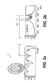
- FIG. 2 is a graphic representation a) of a transfer function with an amplitude maximum for part of the blades of the rotor wheel and b) of another form of representation of the transfer function for a single blade with the maximum frequency being referred to the amplitude maximum of a blade, actually with a blisk not sufficiently decoupled in accordance with the state of the art,
- FIG. 3 is a graphic representation of the transfer functions as per FIG. 2 , however with blades decoupled in accordance with the present invention using extra masses for clearly identifying the natural frequency of the respective blade,
- FIG. 4 is an equivalent blisk model (EBM) for optimum calculation of the correction of the frequency average value
- FIG. 5 is a block diagram for iterative correction of blade frequency distributions determined by measurement.
- the blisk-type rotor wheel 1 to be examined is placed on a foamed plastic mat 2 to provide a virtually free condition.
- the rotor wheel 1 comprises a disk 3 which has blades 4 integrally formed onto its outer circumference.
- all other blades 4 have specific, identical extra masses 7 in the form of small metallic cylinders fixed to them at always the same location, here in the area between blade tip 5 and blade leading edge 6 .
- the respective extra mass 7 is fixed to a side of the blade by means of an easily removable bonding agent, here beeswax, applied to a face of the metallic cylinder.
- the respective blade under investigation 4 .
- the other blades 4 will in the same manner be subjected to the investigation—in each case without extra mass 7 .
- the impact pulse is applied to the respective blade under investigation 4 . 1 always at the same location, under the same angle and with the same magnitude.
- a transfer function is now calculated from the force input signals and the vibratory response signals for each of the, for example, 80 blades of the blisk 11 of a high-pressure compressor and each family of modes (1 st bending, 2 nd bending, 1 st torsion, 2 nd torsion etc.).
- the maximum frequencies f i pertaining to the amplitude maxima ( FIG. 3 b ), which occur isolated in the transfer functions H[m/s/N] due to the blade under measurement being decoupled from the other blades fitted with extra masses, are used as input values for the relative blade natural frequency distribution (f i -f i,mean )/f i,mean ) ( FIG. 3 b ).
- the blade natural frequency distribution of the blisk so determined for all families of modes enables reliable statements to be made on blade mistuning or blade behavior in operation and, finally, on the quality and service-life of the blisk.
- FIG. 2 a shows the transfer function of the vibratory responses of the blisk blades on the basis of transfer functions determined by measurement.
- the representation of a transfer function H[m/s/N] for the amplitude maximum of a single blade (no. 20 ) in FIG. 2 b clearly shows that the blade natural frequency is not definitely identifiable due to coupling effects, as a result of which a reliable assessment of the blisk is not possible.
- the blade natural frequency on blade no. 20 is definitely identifiable due to the single frequency maximum ( FIG. 3 b ) pertaining to the respective amplitude maximum ( FIG. 3 a ).
- the blade frequency distributions determined by the above method can be used to tune a finite element model and, thus, to calculate forced vibratory responses which, finally, supply information substantial for optimum positioning of strain gauges.
- the frequency distribution determined by measurement is given to the model via automated adaptation of the blade stiffness k b,i in, for example, a FORTRAN code, and the pulse excitation of the measurement is simulated.
- the distribution determined by means of a time-step integration method will, on average, be below the specified measurement, so that an iterative increase of the blade stiffness according to FIG. 5 is required until the frequencies determined by measurement are reached.
- the iteration process shown in FIG. 5 can be accomplished selectively on one or a few blades to reduce computation time.
Landscapes
- Physics & Mathematics (AREA)
- General Physics & Mathematics (AREA)
- Engineering & Computer Science (AREA)
- Mechanical Engineering (AREA)
- General Engineering & Computer Science (AREA)
- Health & Medical Sciences (AREA)
- Life Sciences & Earth Sciences (AREA)
- Chemical & Material Sciences (AREA)
- Analytical Chemistry (AREA)
- Biochemistry (AREA)
- General Health & Medical Sciences (AREA)
- Immunology (AREA)
- Pathology (AREA)
- Acoustics & Sound (AREA)
- Structures Of Non-Positive Displacement Pumps (AREA)
- Turbine Rotor Nozzle Sealing (AREA)
- Measurement Of Mechanical Vibrations Or Ultrasonic Waves (AREA)
Applications Claiming Priority (3)
| Application Number | Priority Date | Filing Date | Title |
|---|---|---|---|
| DE102007016369 | 2007-04-03 | ||
| DE102007016369.1 | 2007-04-03 | ||
| DE102007016369A DE102007016369A1 (de) | 2007-04-03 | 2007-04-03 | Verfahren zur Ermittlung der Schaufelverstimmung bei Laufrädern in Integralbauweise |
Publications (2)
| Publication Number | Publication Date |
|---|---|
| US20100286934A1 US20100286934A1 (en) | 2010-11-11 |
| US8024137B2 true US8024137B2 (en) | 2011-09-20 |
Family
ID=39672554
Family Applications (1)
| Application Number | Title | Priority Date | Filing Date |
|---|---|---|---|
| US12/078,608 Active 2029-10-21 US8024137B2 (en) | 2007-04-03 | 2008-04-02 | Method for determining blade mistuning on integrally manufactured rotor wheels |
Country Status (4)
| Country | Link |
|---|---|
| US (1) | US8024137B2 (de) |
| EP (1) | EP1988391B1 (de) |
| CA (1) | CA2627788C (de) |
| DE (1) | DE102007016369A1 (de) |
Cited By (7)
| Publication number | Priority date | Publication date | Assignee | Title |
|---|---|---|---|---|
| US20120198938A1 (en) * | 2011-02-08 | 2012-08-09 | Lomenzo Richard A | Rig for measuring bladed component mistuning |
| US20130276543A1 (en) * | 2012-04-20 | 2013-10-24 | The Regents Of The University Of Michigan | Virtual noncontact excitation |
| US10851655B2 (en) | 2017-02-20 | 2020-12-01 | Rolls-Royce Plc | Fan |
| US11434764B2 (en) | 2018-08-13 | 2022-09-06 | Raytheon Technologies Corporation | Process for repairing turbine engine components |
| US20230213485A1 (en) * | 2019-12-03 | 2023-07-06 | MTU Aero Engines AG | Method and apparatus for determining at least one mechanical parameter of a mechanical object |
| US20230315949A1 (en) * | 2022-04-05 | 2023-10-05 | Raytheon Technologies Corporation | Systems and methods for structural analysis for inspected bladed rotors |
| US12523979B2 (en) | 2022-04-05 | 2026-01-13 | Rtx Corporation | Method of repairing a stack of integrally bladed rotors |
Families Citing this family (11)
| Publication number | Priority date | Publication date | Assignee | Title |
|---|---|---|---|---|
| EP2431605A1 (de) * | 2010-09-21 | 2012-03-21 | Siemens Aktiengesellschaft | Verfahren und Vorrichtung zur Bestimmung einer Kenngröße der Schaufelfrequenz des Rotors einer Windturbine und Betriebsverfahren für eine Windturbine |
| WO2012177659A2 (en) * | 2011-06-20 | 2012-12-27 | Vibrant Corporation | Part evaluation system/method using both resonance and surface vibration data |
| DE102012109225A1 (de) | 2012-09-28 | 2014-04-03 | Ihi Charging Systems International Gmbh | Laufrad zur Ermittlung des Schwingungsverhaltens von Laufradschaufeln, Prüfstand zur Ermittlung des Schwingungsverhaltens von Laufradschaufeln und ein Verfahren zur Ermittlung des Schwingungsverhaltens von Laufradschaufeln |
| CN105352702A (zh) * | 2015-12-17 | 2016-02-24 | 华中科技大学 | 一种自坠落冲击装置 |
| DE102017114153B4 (de) * | 2017-06-26 | 2020-08-20 | Gottfried Wilhelm Leibniz Universität Hannover | Elektromagnetischer Schwingungsanreger zur Schwingungsanregung der Schaufeln eines Schaufelkranzes |
| CN110095243B (zh) * | 2019-06-05 | 2023-12-01 | 哈尔滨汽轮机厂有限责任公司 | 一种汽轮机动叶片固有频率的测量装置 |
| CN112985721A (zh) * | 2019-12-13 | 2021-06-18 | 中国航发商用航空发动机有限责任公司 | 涡轮转子叶片振动特性的检测装置和检测方法 |
| CN111191367B (zh) * | 2019-12-30 | 2023-12-12 | 西安理工大学 | 含有成组围带的整圈失谐叶盘振动局部化的计算方法 |
| US11865655B2 (en) * | 2020-01-20 | 2024-01-09 | Blade Diagnostics Corporation | Techniques for automated maintenance of integrally bladed rotors |
| CN113868797B (zh) * | 2021-09-28 | 2024-06-11 | 合肥工业大学 | 一种叶盘减振结构中调谐质量阻尼器阵列的动态设计方法 |
| CN120404029B (zh) * | 2025-07-03 | 2025-08-26 | 中国航发湖南动力机械研究所 | 一种整体叶盘结构叶片失谐频率快速试验辨识方法 |
Citations (4)
| Publication number | Priority date | Publication date | Assignee | Title |
|---|---|---|---|---|
| US3582036A (en) * | 1968-06-24 | 1971-06-01 | Rafael M Condis | Mold for making honeycombs |
| US6629463B2 (en) | 2000-10-10 | 2003-10-07 | Snecma Moteurs | Acoustic inspection of one-piece bladed wheels |
| US20040243310A1 (en) * | 2003-05-29 | 2004-12-02 | Griffin Jerry H. | Fundamental mistuning model for determining system properties and predicting vibratory response of bladed disks |
| US7497664B2 (en) * | 2005-08-16 | 2009-03-03 | General Electric Company | Methods and apparatus for reducing vibrations induced to airfoils |
Family Cites Families (1)
| Publication number | Priority date | Publication date | Assignee | Title |
|---|---|---|---|---|
| FR2869069B1 (fr) * | 2004-04-20 | 2008-11-21 | Snecma Moteurs Sa | Procede pour introduire un desaccordage volontaire sur une roue aubagee de turbomachine roue aubagee presentant un desaccordage volontaire |
-
2007
- 2007-04-03 DE DE102007016369A patent/DE102007016369A1/de not_active Withdrawn
-
2008
- 2008-03-31 CA CA2627788A patent/CA2627788C/en active Active
- 2008-03-31 EP EP08153755.7A patent/EP1988391B1/de active Active
- 2008-04-02 US US12/078,608 patent/US8024137B2/en active Active
Patent Citations (5)
| Publication number | Priority date | Publication date | Assignee | Title |
|---|---|---|---|---|
| US3582036A (en) * | 1968-06-24 | 1971-06-01 | Rafael M Condis | Mold for making honeycombs |
| US6629463B2 (en) | 2000-10-10 | 2003-10-07 | Snecma Moteurs | Acoustic inspection of one-piece bladed wheels |
| US20040243310A1 (en) * | 2003-05-29 | 2004-12-02 | Griffin Jerry H. | Fundamental mistuning model for determining system properties and predicting vibratory response of bladed disks |
| US7082371B2 (en) | 2003-05-29 | 2006-07-25 | Carnegie Mellon University | Fundamental mistuning model for determining system properties and predicting vibratory response of bladed disks |
| US7497664B2 (en) * | 2005-08-16 | 2009-03-03 | General Electric Company | Methods and apparatus for reducing vibrations induced to airfoils |
Non-Patent Citations (3)
| Title |
|---|
| Beirow, B.: Experimentelle and numerische Untersuchungen hinsichtlich einer Festigkeitsauslegungsoptimierung von Hochdruckverdichterschaufelscheiben unter besonderer Berucksichtigung von Mistuningeffekten, DLRG-Kongress 2003, ISSN 0700-4083. |
| Pierre, Christophe, et al.: Experimental Investigation of Mistuned Bladed Disk Vibration. In: Proceedings of the 5th National Turbine Engine Gigh Cycle Fatigue Conference, Chandler, Arizona, Mar. 2000, pp. 1-7. |
| Server, I.A.: Experimental Validation of Tubomachinery Blade Vibration Predictions. Ph.D.-thesis, University of London (Imperial college) 2004. |
Cited By (10)
| Publication number | Priority date | Publication date | Assignee | Title |
|---|---|---|---|---|
| US20120198938A1 (en) * | 2011-02-08 | 2012-08-09 | Lomenzo Richard A | Rig for measuring bladed component mistuning |
| US8505384B2 (en) * | 2011-02-08 | 2013-08-13 | United Technologies Corporation | Rig for measuring bladed component mistuning |
| US20130276543A1 (en) * | 2012-04-20 | 2013-10-24 | The Regents Of The University Of Michigan | Virtual noncontact excitation |
| US9279739B2 (en) * | 2012-04-20 | 2016-03-08 | The Regents Of The University Of Michigan, University Of Michigan Office Of Technology Transfer | Virtual noncontact excitation |
| US10851655B2 (en) | 2017-02-20 | 2020-12-01 | Rolls-Royce Plc | Fan |
| US11434764B2 (en) | 2018-08-13 | 2022-09-06 | Raytheon Technologies Corporation | Process for repairing turbine engine components |
| US20230213485A1 (en) * | 2019-12-03 | 2023-07-06 | MTU Aero Engines AG | Method and apparatus for determining at least one mechanical parameter of a mechanical object |
| US12292409B2 (en) * | 2019-12-03 | 2025-05-06 | MTU Aero Engines AG | Method and apparatus for determining mechanical parameters by means of mechanical excitations |
| US20230315949A1 (en) * | 2022-04-05 | 2023-10-05 | Raytheon Technologies Corporation | Systems and methods for structural analysis for inspected bladed rotors |
| US12523979B2 (en) | 2022-04-05 | 2026-01-13 | Rtx Corporation | Method of repairing a stack of integrally bladed rotors |
Also Published As
| Publication number | Publication date |
|---|---|
| CA2627788A1 (en) | 2008-10-03 |
| EP1988391A2 (de) | 2008-11-05 |
| DE102007016369A1 (de) | 2008-10-09 |
| CA2627788C (en) | 2013-06-11 |
| EP1988391B1 (de) | 2014-06-18 |
| US20100286934A1 (en) | 2010-11-11 |
| EP1988391A3 (de) | 2013-10-09 |
Similar Documents
| Publication | Publication Date | Title |
|---|---|---|
| US20100286934A1 (en) | Method for determining blade mistuning on integrally manufactured rotor wheels | |
| US20080014091A1 (en) | Frequency tailored thickness blade for a turbomachine wheel | |
| US20040243310A1 (en) | Fundamental mistuning model for determining system properties and predicting vibratory response of bladed disks | |
| US8171632B2 (en) | Method of manufacturing integrally designed rotor wheels to exhibit an essentially identical natural frequency and mass using chemical etch machining | |
| JP2012052536A (ja) | エーロフォイルの健全性を監視するためのシステムおよび方法 | |
| Beirow et al. | On the influence of strain gauge instrumentation on blade vibrations of integral blisk compressor rotors applying a discrete model | |
| Hou | Cracking-induced mistuning in bladed disks | |
| Armstrong | Recent blade vibration techniques | |
| Kenyon et al. | Aerodynamic effects on blade vibratory stress variations | |
| US12292409B2 (en) | Method and apparatus for determining mechanical parameters by means of mechanical excitations | |
| Beirow et al. | Mistuning and damping analysis of a radial turbine blisk in varying ambient conditions | |
| Hemberger et al. | Mistuning modeling and its validation for small turbine wheels | |
| Strehlau et al. | Experimental and numerical investigations of HPC blisks with a focus on travelling waves | |
| CN120277923A (zh) | 一种带涂层叶片高周疲劳强度分析方法及系统 | |
| Jeffers et al. | A novel technique for the measurement of blade damping using piezoelectric actuators | |
| JPH09145530A (ja) | 配管系疲労評価装置 | |
| CN120404029B (zh) | 一种整体叶盘结构叶片失谐频率快速试验辨识方法 | |
| Nakos et al. | On the Influence of Installation on the Forced Responce of Radial Turbine Wheels | |
| CN115199352B (zh) | 基于发动机振动识别发动机转子的不平衡的方法 | |
| Simmons et al. | Effects of stator flow distortion on rotating blade endurance: Part 2—Stress analysis and failure criteria | |
| Orsagh et al. | Examination of successful modal analysis techniques used for bladed-disk assemblies | |
| Honisch et al. | Modelling of industrial blade integrated disks (blisks) with regard to mistuning | |
| EP4621374A1 (de) | System und verfahren zur schätzung einer lebensdauer einer komponente eines flugzeugkraftwerks | |
| Frank et al. | Investigation of Blade and Disc Vibrations on the Upgraded Power Turbine for the THM 1304 Gas Turbine | |
| Qin et al. | High frequency modal test and dynamic performance evaluation of turbine rotor blades |
Legal Events
| Date | Code | Title | Description |
|---|---|---|---|
| AS | Assignment |
Owner name: ROLLS-ROYCE DEUTSCHLAND LTD & CO KG, GERMANY Free format text: ASSIGNMENT OF ASSIGNORS INTEREST;ASSIGNORS:KUEHHORN, ARNOLD;BEIROW, BERND;REEL/FRAME:020787/0537 Effective date: 20080402 |
|
| STCF | Information on status: patent grant |
Free format text: PATENTED CASE |
|
| FPAY | Fee payment |
Year of fee payment: 4 |
|
| MAFP | Maintenance fee payment |
Free format text: PAYMENT OF MAINTENANCE FEE, 8TH YEAR, LARGE ENTITY (ORIGINAL EVENT CODE: M1552); ENTITY STATUS OF PATENT OWNER: LARGE ENTITY Year of fee payment: 8 |
|
| MAFP | Maintenance fee payment |
Free format text: PAYMENT OF MAINTENANCE FEE, 12TH YEAR, LARGE ENTITY (ORIGINAL EVENT CODE: M1553); ENTITY STATUS OF PATENT OWNER: LARGE ENTITY Year of fee payment: 12 |