US8020467B2 - Industrial robot - Google Patents

Industrial robot Download PDF

Info

Publication number
US8020467B2
US8020467B2 US12/785,790 US78579010A US8020467B2 US 8020467 B2 US8020467 B2 US 8020467B2 US 78579010 A US78579010 A US 78579010A US 8020467 B2 US8020467 B2 US 8020467B2
Authority
US
United States
Prior art keywords
axis
arm
motor
cable
robot
Prior art date
Legal status (The legal status is an assumption and is not a legal conclusion. Google has not performed a legal analysis and makes no representation as to the accuracy of the status listed.)
Expired - Fee Related
Application number
US12/785,790
Other versions
US20100229671A1 (en
Inventor
Kazuhiro Haniya
Atsushi Ichibangase
Koichi Yamaguchi
Current Assignee (The listed assignees may be inaccurate. Google has not performed a legal analysis and makes no representation or warranty as to the accuracy of the list.)
Yaskawa Electric Corp
Original Assignee
Yaskawa Electric Corp
Priority date (The priority date is an assumption and is not a legal conclusion. Google has not performed a legal analysis and makes no representation as to the accuracy of the date listed.)
Filing date
Publication date
Application filed by Yaskawa Electric Corp filed Critical Yaskawa Electric Corp
Priority to US12/785,790 priority Critical patent/US8020467B2/en
Publication of US20100229671A1 publication Critical patent/US20100229671A1/en
Application granted granted Critical
Publication of US8020467B2 publication Critical patent/US8020467B2/en
Anticipated expiration legal-status Critical
Expired - Fee Related legal-status Critical Current

Links

Images

Classifications

    • BPERFORMING OPERATIONS; TRANSPORTING
    • B25HAND TOOLS; PORTABLE POWER-DRIVEN TOOLS; MANIPULATORS
    • B25JMANIPULATORS; CHAMBERS PROVIDED WITH MANIPULATION DEVICES
    • B25J19/00Accessories fitted to manipulators, e.g. for monitoring, for viewing; Safety devices combined with or specially adapted for use in connection with manipulators
    • BPERFORMING OPERATIONS; TRANSPORTING
    • B25HAND TOOLS; PORTABLE POWER-DRIVEN TOOLS; MANIPULATORS
    • B25JMANIPULATORS; CHAMBERS PROVIDED WITH MANIPULATION DEVICES
    • B25J17/00Joints
    • B25J17/02Wrist joints
    • B25J17/0283Three-dimensional joints
    • BPERFORMING OPERATIONS; TRANSPORTING
    • B25HAND TOOLS; PORTABLE POWER-DRIVEN TOOLS; MANIPULATORS
    • B25JMANIPULATORS; CHAMBERS PROVIDED WITH MANIPULATION DEVICES
    • B25J18/00Arms
    • B25J18/005Arms having a curved shape
    • BPERFORMING OPERATIONS; TRANSPORTING
    • B25HAND TOOLS; PORTABLE POWER-DRIVEN TOOLS; MANIPULATORS
    • B25JMANIPULATORS; CHAMBERS PROVIDED WITH MANIPULATION DEVICES
    • B25J19/00Accessories fitted to manipulators, e.g. for monitoring, for viewing; Safety devices combined with or specially adapted for use in connection with manipulators
    • B25J19/0025Means for supplying energy to the end effector
    • YGENERAL TAGGING OF NEW TECHNOLOGICAL DEVELOPMENTS; GENERAL TAGGING OF CROSS-SECTIONAL TECHNOLOGIES SPANNING OVER SEVERAL SECTIONS OF THE IPC; TECHNICAL SUBJECTS COVERED BY FORMER USPC CROSS-REFERENCE ART COLLECTIONS [XRACs] AND DIGESTS
    • Y10TECHNICAL SUBJECTS COVERED BY FORMER USPC
    • Y10TTECHNICAL SUBJECTS COVERED BY FORMER US CLASSIFICATION
    • Y10T74/00Machine element or mechanism
    • Y10T74/20Control lever and linkage systems
    • Y10T74/20207Multiple controlling elements for single controlled element
    • Y10T74/20305Robotic arm
    • Y10T74/20311Robotic arm including power cable or connector
    • YGENERAL TAGGING OF NEW TECHNOLOGICAL DEVELOPMENTS; GENERAL TAGGING OF CROSS-SECTIONAL TECHNOLOGIES SPANNING OVER SEVERAL SECTIONS OF THE IPC; TECHNICAL SUBJECTS COVERED BY FORMER USPC CROSS-REFERENCE ART COLLECTIONS [XRACs] AND DIGESTS
    • Y10TECHNICAL SUBJECTS COVERED BY FORMER USPC
    • Y10TTECHNICAL SUBJECTS COVERED BY FORMER US CLASSIFICATION
    • Y10T74/00Machine element or mechanism
    • Y10T74/20Control lever and linkage systems
    • Y10T74/20207Multiple controlling elements for single controlled element
    • Y10T74/20305Robotic arm
    • Y10T74/20317Robotic arm including electric motor
    • YGENERAL TAGGING OF NEW TECHNOLOGICAL DEVELOPMENTS; GENERAL TAGGING OF CROSS-SECTIONAL TECHNOLOGIES SPANNING OVER SEVERAL SECTIONS OF THE IPC; TECHNICAL SUBJECTS COVERED BY FORMER USPC CROSS-REFERENCE ART COLLECTIONS [XRACs] AND DIGESTS
    • Y10TECHNICAL SUBJECTS COVERED BY FORMER USPC
    • Y10TTECHNICAL SUBJECTS COVERED BY FORMER US CLASSIFICATION
    • Y10T74/00Machine element or mechanism
    • Y10T74/20Control lever and linkage systems
    • Y10T74/20207Multiple controlling elements for single controlled element
    • Y10T74/20305Robotic arm
    • Y10T74/20329Joint between elements
    • Y10T74/20335Wrist

Definitions

  • This invention relates to an industrial robot, and more particularly to an arc-welding vertical multijoint robot.
  • This six-axis vertical multijoint robot has a turning base (a first basic axis) adapted to turn around a vertical axis on a base stand, a lower arm (a second basic axis) attached to the turning base and adapted to frontwardly and rearwardly swing, an upper arm (a third arm) attached to an end of the lower arm and adapted to upwardly and downwardly swing, and a three-degree-of-freedom wrist portion (first to third wrist axes) attached to an end of the upper arm.
  • the arc welding torch can take a given attitude at a given position, so that arc welding can be freely performed.
  • FIG. 8 is a side view of a conventional arc welding robot.
  • reference numeral 3 designates a lower arm, which is pivotally supported by a turning base (not shown) and frontwardly and rearwardly swings.
  • Reference numeral 4 denotes an upper arm that is supported rotatably and pivotally around a U-axis (which is an axis perpendicular to a paper surface) at an end of the lower arm 3 and that swings upwardly and downwardly.
  • Reference numeral 5 designates a wrist portion attached to an end of the upper arm.
  • the wrist portion 5 comprises a body 6 that rotates around an R-axis extending in the direction of length of the upper arm, a swinging element 7 that is pivotally supported at an end of the body 6 and that swings around a B-axis (which is an axis perpendicular to the paper surface) perpendicular to the R-axis, and a rotating element 8 that is provided at an end of the swinging element 7 and that rotates around a T-axis perpendicular to the B-axis.
  • a body 6 that rotates around an R-axis extending in the direction of length of the upper arm
  • a swinging element 7 that is pivotally supported at an end of the body 6 and that swings around a B-axis (which is an axis perpendicular to the paper surface) perpendicular to the R-axis
  • a rotating element 8 that is provided at an end of the swinging element 7 and that rotates around a T-axis perpendicular to the B-axis.
  • Reference numeral 9 designates a welding torch fixed to the rotating portion 8 through a torch clamp 10 .
  • Reference numeral 11 denotes a wire feeding unit that is fixed onto the upper arm 2 and that draws out a welding wire from a wire storage unit (for example, a wire reel (not shown)) and pushes out the welding wire to the welding torch 9 .
  • Reference numeral 12 designates a conduit cable that connects the welding torch 9 and the wire feeding unit 11 .
  • the conduit cable 12 is produced by bundling a welding supply cable and a shielding gas supply hose around a protective tube for feeding the welding wire to the welding torch 9 .
  • the conventional arc welding robot has a problem that when the swinging element 7 is caused swing around the B-axis so that the welding torch 9 is made to swing upwardly and downwardly with respect to the upper arm 4 , the conduit cable 12 bends to thereby hinder the feeding of the welding wire. Also, the conventional arc welding robot has another problem that when the rotating element 8 is rotated around the T-axis, the conduit cable 12 twines around the wrist portion 5 and the upper arm 4 .
  • the conduit cable 12 has been caused to extend over the upper arm 4 in such a way as to form a large arch thereover, as shown in FIG. 7 , so that a motion of the welding torch 9 is absorbed by deformation of the arch.
  • the conduit cable 12 which has formed a large arch, causes interference with a work and a peripheral device, so that the arch cannot needlessly be enlarged. Thus, complete solution of the problems has not been achieved.
  • the invention provides an industrial robot, wherein a cable or the like spanned between an end effector and an upper arm has less bending due to a motion of a wrist portion, wherein the cable or the like does not twine around the upper arm, and wherein the cable or the like does not interfere with a peripheral device.
  • an industrial robot having a wrist portion provided at an end of an arm.
  • the wrist portion has a body, attached to the end of the arm and adapted to rotate around a first axis extending in a direction of length of the arm, a swinging element, attached to an end of the body and adapted to swing around a second axis perpendicular to the first axis, and a rotating element attached to an end of the swinging element and adapted to rotate a third axis.
  • a passage opening from which a cable or the like for supplying power, a signal, or a material to an end effector attached to the rotating element is drawn out, is opened at a place, at which the body intersects with a center of the first axis.
  • a motor and a reduction gear which are used for driving the body, are provided in the arm concentrically with the first axis.
  • the motor and the reduction gear are respectively a hollow shaft motor and a hollow shaft reduction gear, each of which has a hollow portion penetrating from anti-load side to load side and is adapted so that the cable or the like is drawn in from the anti-load side of the hollow portion and drawn out to the load side of the hollow portion.
  • a motor is provided in the arm by being off-centered from the first axis.
  • a reduction gear connected to the motor, for driving the body is provided in the arm concentrically with the first axis.
  • the reduction gear is a hollow shaft reduction gear, which has a hollow portion penetrating from anti-load side to load side and is adapted so that the cable or the like is drawn in from the anti-load side of the hollow portion and drawn out to the load side of the hollow portion.
  • an industrial robot having a wrist portion provided at an end of an arm.
  • the wrist portion having a body, attached to the end of the arm and adapted to rotate around a first axis extending in a direction of length of the arm, a swinging element, attached to an end of the body and adapted to swing around a second axis perpendicular to the first axis, and a rotating element attached to an end of the swinging element and adapted to rotate a third axis.
  • the body has two parts extending with the first axis to be shaped like a fork and swingably supports the swinging element by sandwiching the swinging element between the two parts shaped like prongs of the fork.
  • the cable or the like drawn out from the passage opening is extended to the end effector through between the prong-like two parts.
  • the swinging element has prong-like parts extending in parallel with the third axis.
  • the cable or the like extends to the end effector through between the prong-like two parts of the swinging element.
  • a restraining piece for restraining the cable from sticking out from between the prong-like two parts is provided between the prong-like parts of the swinging element.
  • an ingress opening is opened in a side surface of the arm.
  • the cable or the like is drawn into an inside of the arm from the ingress opening and extended from the inside of the arm to the body along the first axis.
  • the rotating element has a cylindrical space that penetrates from a front end to a rear end thereof and is provided concentrically with the third axis.
  • the end effector is provided by being inserted into the space.
  • a first motor for driving the body is provided in the arm concentrically with the first axis.
  • a second motor for driving the swinging element, and a third motor for driving the rotating element are provided in the body in such a way as to perpendicular to the first axis. Power of the second motor and power of the third motor are transmitted to the swinging element and the rotating element through a belt pulley mechanism disposed between the prong-like two parts of the body.
  • a power/signal line for driving each of the second motor and the third motor is provided at a place off-centered from the center of the first axis serving and extended from the inside of the arm to an inside of the body.
  • the end effector is an arc welding torch.
  • the cable or the like is a conduit cable.
  • a wire feeding unit for feeding a welding wire to the torch is attached to a rear of the arm.
  • the wire feeding unit is attached in a direction in which the welding wire is fed in parallel with the first axis.
  • the cable or the like is protected by being covered with a protective tube that is produced by coating a coil spring with a resin.
  • FIG. 1 is a side view of an industrial robot, which shows a first embodiment of the invention
  • FIG. 2 is a stereograph of the industrial robot shown in FIG. 1 ;
  • FIG. 3 is a plan sectional view of an upper arm of the industrial robot shown in FIG. 1 ;
  • FIG. 4 is a stereograph of an intermediate shaft
  • FIG. 5 is a side view of a wrist portion of an industrial robot, which shows a second embodiment of the invention.
  • FIG. 6 is a plan sectional view showing the internal mechanism of the wrist portion shown in FIG. 5 ;
  • FIG. 7 is a trihedral view of an industrial robot, which shows a third embodiment of the invention.
  • FIG. 8 is a side view of a conventional industrial robot, which shows prior art.
  • FIG. 1 is a side view of an industrial robot, which shows a first embodiment of the invention.
  • reference numeral 1 designates a base stand of an industrial robot.
  • a turning base 2 is mounted on the base stand 1 in such a way as to be turnable around a vertical axis (an S-axis)
  • a lower arm 3 is supported on the turning base 2 in such a manner as to be turnable around a horizontal axis (an L-axis), and swings in a front-rear direction.
  • An upper arm 4 is supported on the top of the lower arm 3 in such a way as to be turnable around a horizontal axis (a U-axis), and swings in an up-down direction.
  • Reference numeral 5 designates a wrist portion attached to an end of the upper arm 4 .
  • the wrist portion 5 comprises a body 6 attached thereto in such a manner as to be rotatable around a central axis (an R-axis: a first wrist axis) extending in the direction of length of the upper arm 4 , a swinging element 7 that is pivotally supported at an end of the body 6 and swings around an axis perpendicular to the R-axis (a B-axis: a second wrist axis), and a rotating element 8 that is provided at an end of the swinging element 7 and rotates around a rotation axis (a T-axis: a third wrist axis).
  • a central axis an R-axis: a first wrist axis
  • a swinging element 7 that is pivotally supported at an end of the body 6 and swings around an axis perpendicular to the R-axis
  • a rotating element 8 that is provided at an end of the swinging element
  • Reference numeral 9 designates a welding torch attached to the rotating element 8
  • reference numeral 11 denotes a wire feeding unit fixed to a rear end of the upper arm 4
  • a welding wire is supplied from a wire reel (not shown) to the wire feeding unit 11 , which feeds the welding wire through a conduit cable 12 to the welding torch 9
  • the conduit cable 12 extends along a side surface of the upper arm 4 in parallel with the R-axis and drawn into the inside thereof from an ingress opening 21 opened in the side surface thereof. Incidentally, a route of the conduit cable 12 from the inside of the upper arm 4 to the welding torch 9 will be described later.
  • conduit cable 12 is protected by being let through a protective tube produced by coating a coil spring with a resin.
  • FIG. 2 is a stereograph of the industrial robot shown in FIG. 1 .
  • the body 6 of the wrist portion 5 is formed having a nearly U-shape in plan view, and has two members 22 and 23 that extend in parallel with the R-axis and is shaped like a fork.
  • the swinging element 7 is sandwiched between the members 22 and 23 and supported in a center impeller manner.
  • the conduit cable 12 having entered the inside of the upper arm 4 from the ingress opening 21 goes out of the passage opening 25 opened in a U-shaped bottom portion 24 of the body 6 again and extends to the swinging element 7 through a space between the members 22 and 23 .
  • the passage opening 25 is an aperture centered around the R-axis, and the conduit cable 12 is disposed to extend from the passage opening 25 toward the swinging element 7 along the R-axis (so that the central axis of the conduit cable 12 coincides with the R-axis).
  • FIG. 3 is a plan sectional view of the upper arm 4 of the industrial robot shown in FIG. 1 , which is taken on line A-A′ of FIG. 1 .
  • reference numeral 31 designates a motor mounted in the upper arm 4 by making the central axis of the rotating shaft thereof coincide with the R-axis, that is, concentrically with the R-axis.
  • the motor 31 rotation-drives the body 6 of the wrist portion around the R-axis through a reduction gear 32 and an intermediate shaft 33 .
  • the intermediate shaft 33 is rotatably supported in the upper arm 4 by bearings 34 and 35 .
  • the intermediate shaft 33 comprises an annular portion 36 supported by the bearing 34 and connected to the reduction gear 32 , a hollow cylindrical portion 37 supported by the bearing 35 and connected to the body 6 , and a connection portion 38 , which is provided at a place offset from the center of rotation (the R-axis).
  • the intermediate shaft 33 is shaped like a crankshaft as a whole (see FIG. 4 ).
  • Reference numeral 39 designates an inside wire.
  • the inside wire 39 is a power line equipped in the body 6 and used for driving a motor (to be described later), which drives the swinging element 7 and the rotating element 8 .
  • the inside wire 39 is drawn into the upper arm 4 from the lower arm 3 and clamped at a point 39 a in the upper arm 4 .
  • the inside wire 39 extends from the point 39 a to a point 39 b by forming an arc around the R-axis to thereby form a toric portion.
  • the inside wire 39 extends from the point 39 b to a point 39 c by forming a U-shaped folding portion.
  • the inside wire 39 extends from the point 39 c to a point 39 d by forming a toric portion around the R-axis again, and is clamped at the point 39 c by the annular portion 36 of the intermediate shaft 33 .
  • the applicant of the present application retains a Utility Model Right for the structure for holding the inside wire 39 from the point 39 a to the point 39 d , as Japanese Utility Model No. 2117576 (JP-UM-B-7-39575).
  • the inside wire 39 extends from the point 39 d along the connection portion 38 of the intermediate shaft 33 (although omitted in drawing, the inside wire 39 is appropriately and firmly bound to the connection portion 38 ) and enters the body 6 through a groove provided in an outer periphery of the hollow portion by bypassing the center (the R-axis) of the hollow cylindrical portion 37 of the intermediate shaft 33 .
  • the conduit cable 12 enters the upper arm 4 from the ingress opening 21 opened in the side surface thereof and goes out from the passage opening 25 of the body 6 through the central hollow portion of the hollow cylindrical portion 37 of the intermediate shaft 33 .
  • the hollow portion and the passage opening are cylinders centered around the R-axis, so that the conduit cable 12 is straightly drawn out along the R-axis to the outside.
  • the conduit cable 12 is centered around the R-axis, while the inside wire 39 is located at a place off-centered from the R-axis. Therefore, when the body 6 rotates around the R-axis, the inside wire 39 goes around the conduit cable 12 like a satellite. Consequently, no interference occurs between the inside wire 39 and the conduit cable 12 .
  • FIG. 5 is a side view of a wrist portion of an industrial robot, which shows a second embodiment of the invention.
  • the wrist portion is illustrated by removing a cover for the right-side surface of the body 6 of the wrist portion 5 so as to display an internal mechanism.
  • reference numeral 51 designates a motor for driving the swinging element 7 .
  • the motor 51 is mounted in the body 6 sideways, that is, in such a way as to be perpendicular to the R-axis, and as to be parallel with the B-axis.
  • a pulley 52 is attached to an output shaft of the motor 51 .
  • Reference numeral 53 designates a reduction gear, which is connected to the swinging element 7 and attached to an end of the body 6 .
  • a pulley 54 is attached to an input shaft of the reduction gear 53 .
  • a timing belt 55 is wound around the pulleys 54 and 52 . That is, power of the motor 51 is transmitted to the reduction gear 53 through a belt pulley mechanism thereby to rotate-drive the swinging element 7 around the B-axis.
  • Reference numeral 56 denotes a motor for driving the rotating element 8 .
  • the motor 56 is mounted in the body 6 sideways. Power of the motor 56 drives the rotating element 8 through another belt pulley (not shown) disposed at the left side (the rear side of a paper surface).
  • the motor 51 and the motor 56 are mounted at places off-centered downwardly from the R-axis. This is employed for preventing the interference between these motors and the conduit cable 12 extending along the R-axis.
  • FIG. 6 is a plan sectional view showing the internal mechanism provided at an end of the wrist portion of the industrial robot shown in FIG. 5 .
  • the swinging element 7 is rotated around the B-axis 90 degrees and brought into a horizontal attitude, that is, an attitude in which the R-axis and the T-axis coincide with each other.
  • constituent elements which are common to this figure and FIG. 5 , are designated by same reference character in these figures, so that the description of such constituent elements is omitted.
  • Reference numeral 61 designates a belt that transmit power of a rotating element driving motor (which corresponds to the motor 56 and is not shown in FIG. 6 ) to a pulley 62 .
  • a bevel gear 63 is attached to the pulley 62 .
  • Reference numeral 64 denotes a transmission shaft axially supported by the swinging element 7 in parallel with the T-axis. Bevel gears 65 and 66 are attached to both ends of the transmission shaft, respectively.
  • the bevel gear 65 engages with the bevel gear 63 .
  • Reference numeral 67 designates a bevel gear attached to the rotating element 8 .
  • the bevel gear 67 meshes with the bevel gear 66 .
  • the power of the rotating element driving motor is transmitted to the rotating element 8 .
  • the rotating element 8 has a cylindrical hollow portion centered around the T-axis.
  • the welding torch 9 penetrates through the hollow portion.
  • the conduit cable 12 is connected to an end portion of the welding torch 9 passed through the rotating element 8 .
  • the conduit cable 12 is disposed concentrically with the R-axis in the space between the members 22 and 23 of the body 6 shaped like a fork.
  • a swinging element driving belt pulley mechanism and a rotating element driving belt pulley mechanism are disposed in the member 22 and the member 23 , respectively.
  • FIG. 7 is a trihedral view of an industrial robot, which shows a third embodiment of the invention, and (a) is a front view thereof, (b) is a plan view thereof, and (c) is a right side view thereof.
  • the basic configuration thereof is the same as those of the first and second embodiments shown in FIGS. 1 to 6 .
  • Constituent elements common thereto are designated by same reference characters, and the description of such constituent elements is omitted.
  • the swinging element 7 has a main body 7 a supporting the rotating element 8 , and two parts 7 b and 7 c , which are provided on the left and right sides of the main body 7 a (as viewed in the right side view thereof) and extend in parallel with a third axis (the T-axis), that is, a rotation center axis of the rotating element 8 , and is shaped like a fork. Ends of the parts 7 b and 7 c are respectively and rotatably supported by the members 22 and 23 , which are provided on the left and right sides of the body 6 , and support the swinging element 7 in a center impeller manner.
  • the conduit cable 12 extends to the rotating element 8 (and further to the welding torch attached to an end of this element) through the space between the members 22 and 23 and the space between the parts 7 a and 7 b.
  • Reference numeral 13 designates a cable support fixed to the part 7 b .
  • the cable support 13 blocks the space between the parts 7 b and 7 c and functions as a restraining piece for restraining the conduit cable 12 from sticking out from between the parts 7 b and 7 c.
  • a connecting piece 14 for connecting the members 22 and 23 of the body 6 is provided therebetween and strains the conduit cable 12 from hanging down from the body 6 .
  • the swinging element 7 of the wrist portion 5 is axis-supported at the end of the body 6 in a center impeller manner in each of the aforementioned embodiments, the swinging element 7 may be supported in a cantilevered manner. That is, the robot may choose a structure in which the swinging element 7 is supported by the member 22 in a cantilevered manner by removing one 23 of the two members 22 and 23 of the body 6 shown in FIG. 2 .
  • conduit cable 12 is drawn into the upper arm 4 from the side surface in each of the embodiments, the conduit cable 12 can be straightly extended along the R-axis from the rear end of the upper arm to the welding torch by configuring the robot as the following first and second modifications.
  • a hollow shaft motor and a hollow shaft reduction gear each of which has a hollow portion penetrating from anti-load side to load side, are employed as the motor 31 and the reduction gear 32 , respectively, so that the conduit cable 12 extends straightly (along the R-axis) in the intermediate shaft 33 through the hollow shaft of the motor 31 and the hollow shaft of the reduction gear 32 .
  • the wire feeding unit 11 is attached thereto so that a direction, in which the welding wire is fed, coincides with the R-axis.
  • This structure can be expected to has the effect of reducing welding wire feeding resistance, because the bend of the conduit cable is small, as compared with the case of drawing the conduit cable 12 into the upper arm 4 from the side surface.
  • the robot may be adapted so that only the reduction gear 32 is changed to the hollow shaft reduction gear, and that the motor 31 is off-centered from the R-axis in parallel therewith and connected to the reduction gear 32 through the belt pulley mechanism.
  • the conduit cable 12 enters the upper arm 4 from the rear end thereof along the R-axis and passes along the side of the motor and then enters the hollow shaft of the reduction gear 32 .
  • the invention is not limited to the arc welding robot.
  • the invention can be applied to all of uses, such as painting, sealing, polishing, and handling. That is, the end effector may be a painting spray gun, a sealing nozzle, a polishing tool, or a mechanical hand.
  • the cable or the like may be a painting hose, a sealing material supply hose, a pneumatic tool driving air hose, a power-tool driving power line or the like.
  • the industrial robot according to the invention has the effect of preventing the interference between the peripheral device or the like and the cable or the like, because the cable or the like for the end effector is provided along the major axis of the upper arm thereof. Because the interference does not occur, occurrences of abrasion of the cable or the like and damage, such as breaking, of the wire, can be averted, so that the robot according to the invention also has the effect of increasing the life of the cable or the like. Further, in the upper arm and the wrist portion, the cable or the like is placed in such a way as to coincide with the center axis of rotation of the wrist portion, while the inside wire for driving the wrist is off-centered from the central axis of rotation thereof.
  • the robot of the invention has the effect of preventing the interference between the inside wire and the cable or the like. Furthermore, even when the wrist portion rotates around the major axis thereof, the cable or the like is only twisted and follows the rotation of the wrist portion, so that no bend of the cable or the like occurs. Thus, change in the feeding resistance of the welding wire, which is fed through the inside of the cable or the like, does not occur. Consequently, the robot of the invention has the effects of stably feeding the welding wire and extremely enhancing welding quality.
  • the invention is useful as an industrial robot, and more particularly as an arc-welding vertical multijoint robot.

Abstract

The present invention is an industrial robot with a cable spanned between and end effector and an upper arm. The cable does not twine around the upper arm or interfere with a peripheral device. A passage opening, through which the cable for supplying power, signals, or materials to an end effector attached to a rotating element is drawn out of a body, is opened at a position where the body intersects the center of a first rotational axis.

Description

CROSS-REFERENCE TO RELATED APPLICATIONS
This is a divisional of U.S. patent application Ser. No. 10/493,139, filed on Apr. 20, 2004, which is a 371 of PCT Application No. PCT/IB02/04355 filed Oct. 22, 2002, which claims priority from Japanese Patent Application No. 2001-324098 filed Oct. 22, 2001, and Japanese Patent Application No. 2002-037386, filed Feb. 14, 2004, all of which applications are incorporated herein by references.
TECHNICAL FIELD
This invention relates to an industrial robot, and more particularly to an arc-welding vertical multijoint robot.
BACKGROUND ART
Nowadays, arc welding robots each produced by attaching an arc welding torch to an end of a six-axis vertical multijoint robot are heavily used in many industrial fields. This six-axis vertical multijoint robot has a turning base (a first basic axis) adapted to turn around a vertical axis on a base stand, a lower arm (a second basic axis) attached to the turning base and adapted to frontwardly and rearwardly swing, an upper arm (a third arm) attached to an end of the lower arm and adapted to upwardly and downwardly swing, and a three-degree-of-freedom wrist portion (first to third wrist axes) attached to an end of the upper arm. In a case where the arc welding torch is attached to an end of the wrist portion, the arc welding torch can take a given attitude at a given position, so that arc welding can be freely performed.
FIG. 8 is a side view of a conventional arc welding robot.
In the figure, reference numeral 3 designates a lower arm, which is pivotally supported by a turning base (not shown) and frontwardly and rearwardly swings. Reference numeral 4 denotes an upper arm that is supported rotatably and pivotally around a U-axis (which is an axis perpendicular to a paper surface) at an end of the lower arm 3 and that swings upwardly and downwardly. Reference numeral 5 designates a wrist portion attached to an end of the upper arm.
The wrist portion 5 comprises a body 6 that rotates around an R-axis extending in the direction of length of the upper arm, a swinging element 7 that is pivotally supported at an end of the body 6 and that swings around a B-axis (which is an axis perpendicular to the paper surface) perpendicular to the R-axis, and a rotating element 8 that is provided at an end of the swinging element 7 and that rotates around a T-axis perpendicular to the B-axis.
Reference numeral 9 designates a welding torch fixed to the rotating portion 8 through a torch clamp 10. Reference numeral 11 denotes a wire feeding unit that is fixed onto the upper arm 2 and that draws out a welding wire from a wire storage unit (for example, a wire reel (not shown)) and pushes out the welding wire to the welding torch 9. Reference numeral 12 designates a conduit cable that connects the welding torch 9 and the wire feeding unit 11. The conduit cable 12 is produced by bundling a welding supply cable and a shielding gas supply hose around a protective tube for feeding the welding wire to the welding torch 9.
However, the conventional arc welding robot has a problem that when the swinging element 7 is caused swing around the B-axis so that the welding torch 9 is made to swing upwardly and downwardly with respect to the upper arm 4, the conduit cable 12 bends to thereby hinder the feeding of the welding wire. Also, the conventional arc welding robot has another problem that when the rotating element 8 is rotated around the T-axis, the conduit cable 12 twines around the wrist portion 5 and the upper arm 4.
To remedy these problems, the conduit cable 12 has been caused to extend over the upper arm 4 in such a way as to form a large arch thereover, as shown in FIG. 7, so that a motion of the welding torch 9 is absorbed by deformation of the arch. However, the conduit cable 12, which has formed a large arch, causes interference with a work and a peripheral device, so that the arch cannot needlessly be enlarged. Thus, complete solution of the problems has not been achieved.
DISCLOSURE OF INVENTION
Accordingly, the invention provides an industrial robot, wherein a cable or the like spanned between an end effector and an upper arm has less bending due to a motion of a wrist portion, wherein the cable or the like does not twine around the upper arm, and wherein the cable or the like does not interfere with a peripheral device.
To solve the problems, according to the invention, there is provided an industrial robot having a wrist portion provided at an end of an arm. The wrist portion has a body, attached to the end of the arm and adapted to rotate around a first axis extending in a direction of length of the arm, a swinging element, attached to an end of the body and adapted to swing around a second axis perpendicular to the first axis, and a rotating element attached to an end of the swinging element and adapted to rotate a third axis. In the industrial robot, a passage opening, from which a cable or the like for supplying power, a signal, or a material to an end effector attached to the rotating element is drawn out, is opened at a place, at which the body intersects with a center of the first axis.
Further, according to another aspect of the invention, a motor and a reduction gear, which are used for driving the body, are provided in the arm concentrically with the first axis. The motor and the reduction gear are respectively a hollow shaft motor and a hollow shaft reduction gear, each of which has a hollow portion penetrating from anti-load side to load side and is adapted so that the cable or the like is drawn in from the anti-load side of the hollow portion and drawn out to the load side of the hollow portion.
Furthermore, according to a specific enhancement, a motor is provided in the arm by being off-centered from the first axis. A reduction gear, connected to the motor, for driving the body is provided in the arm concentrically with the first axis. The reduction gear is a hollow shaft reduction gear, which has a hollow portion penetrating from anti-load side to load side and is adapted so that the cable or the like is drawn in from the anti-load side of the hollow portion and drawn out to the load side of the hollow portion.
Further, according to another specific enhancement, there is provided an industrial robot having a wrist portion provided at an end of an arm. The wrist portion having a body, attached to the end of the arm and adapted to rotate around a first axis extending in a direction of length of the arm, a swinging element, attached to an end of the body and adapted to swing around a second axis perpendicular to the first axis, and a rotating element attached to an end of the swinging element and adapted to rotate a third axis. In this industrial robot, the body has two parts extending with the first axis to be shaped like a fork and swingably supports the swinging element by sandwiching the swinging element between the two parts shaped like prongs of the fork. A passage opening, from which a cable or the like for supplying power, a signal, or a material to an end effector attached to the rotating element is drawn out, is opened at a place, at which a bottom portion of the prong-like parts of the body intersects with a center of the first axis. The cable or the like drawn out from the passage opening is extended to the end effector through between the prong-like two parts.
Furthermore, according to another specific enhancement, the swinging element has prong-like parts extending in parallel with the third axis. The cable or the like extends to the end effector through between the prong-like two parts of the swinging element. A restraining piece for restraining the cable from sticking out from between the prong-like two parts is provided between the prong-like parts of the swinging element.
Further, according to another specific enhancement, an ingress opening is opened in a side surface of the arm. The cable or the like is drawn into an inside of the arm from the ingress opening and extended from the inside of the arm to the body along the first axis.
Furthermore, according to another specific enhancement, the rotating element has a cylindrical space that penetrates from a front end to a rear end thereof and is provided concentrically with the third axis. The end effector is provided by being inserted into the space.
Further, according to another specific enhancement, a first motor for driving the body is provided in the arm concentrically with the first axis. A second motor for driving the swinging element, and a third motor for driving the rotating element are provided in the body in such a way as to perpendicular to the first axis. Power of the second motor and power of the third motor are transmitted to the swinging element and the rotating element through a belt pulley mechanism disposed between the prong-like two parts of the body.
Furthermore, according to another specific enhancement, a power/signal line for driving each of the second motor and the third motor is provided at a place off-centered from the center of the first axis serving and extended from the inside of the arm to an inside of the body.
Further, according to another specific enhancement, the end effector is an arc welding torch. The cable or the like is a conduit cable.
Furthermore, according to another specific enhancement, a wire feeding unit for feeding a welding wire to the torch is attached to a rear of the arm.
Further, according to another specific enhancement, the wire feeding unit is attached in a direction in which the welding wire is fed in parallel with the first axis.
Furthermore, according to another specific enhancement, the cable or the like is protected by being covered with a protective tube that is produced by coating a coil spring with a resin.
BRIEF DESCRIPTION OF DRAWINGS
FIG. 1 is a side view of an industrial robot, which shows a first embodiment of the invention;
FIG. 2 is a stereograph of the industrial robot shown in FIG. 1;
FIG. 3 is a plan sectional view of an upper arm of the industrial robot shown in FIG. 1;
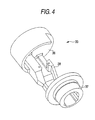
FIG. 4 is a stereograph of an intermediate shaft;
FIG. 5 is a side view of a wrist portion of an industrial robot, which shows a second embodiment of the invention;
FIG. 6 is a plan sectional view showing the internal mechanism of the wrist portion shown in FIG. 5;
FIG. 7 is a trihedral view of an industrial robot, which shows a third embodiment of the invention; and
FIG. 8 is a side view of a conventional industrial robot, which shows prior art.
BEST MODE FOR CARRYING OUT THE INVENTION
Hereinafter, embodiments of the invention are described with reference to the accompanying drawings.
FIG. 1 is a side view of an industrial robot, which shows a first embodiment of the invention.
In the figure, reference numeral 1 designates a base stand of an industrial robot. A turning base 2 is mounted on the base stand 1 in such a way as to be turnable around a vertical axis (an S-axis), A lower arm 3 is supported on the turning base 2 in such a manner as to be turnable around a horizontal axis (an L-axis), and swings in a front-rear direction. An upper arm 4 is supported on the top of the lower arm 3 in such a way as to be turnable around a horizontal axis (a U-axis), and swings in an up-down direction.
Reference numeral 5 designates a wrist portion attached to an end of the upper arm 4. The wrist portion 5 comprises a body 6 attached thereto in such a manner as to be rotatable around a central axis (an R-axis: a first wrist axis) extending in the direction of length of the upper arm 4, a swinging element 7 that is pivotally supported at an end of the body 6 and swings around an axis perpendicular to the R-axis (a B-axis: a second wrist axis), and a rotating element 8 that is provided at an end of the swinging element 7 and rotates around a rotation axis (a T-axis: a third wrist axis).
Reference numeral 9 designates a welding torch attached to the rotating element 8, and reference numeral 11 denotes a wire feeding unit fixed to a rear end of the upper arm 4. A welding wire is supplied from a wire reel (not shown) to the wire feeding unit 11, which feeds the welding wire through a conduit cable 12 to the welding torch 9. The conduit cable 12 extends along a side surface of the upper arm 4 in parallel with the R-axis and drawn into the inside thereof from an ingress opening 21 opened in the side surface thereof. Incidentally, a route of the conduit cable 12 from the inside of the upper arm 4 to the welding torch 9 will be described later.
Further, the conduit cable 12 is protected by being let through a protective tube produced by coating a coil spring with a resin.
FIG. 2 is a stereograph of the industrial robot shown in FIG. 1.
The body 6 of the wrist portion 5 is formed having a nearly U-shape in plan view, and has two members 22 and 23 that extend in parallel with the R-axis and is shaped like a fork. The swinging element 7 is sandwiched between the members 22 and 23 and supported in a center impeller manner. The conduit cable 12 having entered the inside of the upper arm 4 from the ingress opening 21 goes out of the passage opening 25 opened in a U-shaped bottom portion 24 of the body 6 again and extends to the swinging element 7 through a space between the members 22 and 23. The passage opening 25 is an aperture centered around the R-axis, and the conduit cable 12 is disposed to extend from the passage opening 25 toward the swinging element 7 along the R-axis (so that the central axis of the conduit cable 12 coincides with the R-axis).
FIG. 3 is a plan sectional view of the upper arm 4 of the industrial robot shown in FIG. 1, which is taken on line A-A′ of FIG. 1.
In the figure, reference numeral 31 designates a motor mounted in the upper arm 4 by making the central axis of the rotating shaft thereof coincide with the R-axis, that is, concentrically with the R-axis. The motor 31 rotation-drives the body 6 of the wrist portion around the R-axis through a reduction gear 32 and an intermediate shaft 33. The intermediate shaft 33 is rotatably supported in the upper arm 4 by bearings 34 and 35. Further, the intermediate shaft 33 comprises an annular portion 36 supported by the bearing 34 and connected to the reduction gear 32, a hollow cylindrical portion 37 supported by the bearing 35 and connected to the body 6, and a connection portion 38, which is provided at a place offset from the center of rotation (the R-axis). The intermediate shaft 33 is shaped like a crankshaft as a whole (see FIG. 4).
Reference numeral 39 designates an inside wire. The inside wire 39 is a power line equipped in the body 6 and used for driving a motor (to be described later), which drives the swinging element 7 and the rotating element 8. The inside wire 39 is drawn into the upper arm 4 from the lower arm 3 and clamped at a point 39 a in the upper arm 4. The inside wire 39 extends from the point 39 a to a point 39 b by forming an arc around the R-axis to thereby form a toric portion. Moreover, the inside wire 39 extends from the point 39 b to a point 39 c by forming a U-shaped folding portion. The inside wire 39 extends from the point 39 c to a point 39 d by forming a toric portion around the R-axis again, and is clamped at the point 39 c by the annular portion 36 of the intermediate shaft 33. Incidentally, the applicant of the present application retains a Utility Model Right for the structure for holding the inside wire 39 from the point 39 a to the point 39 d, as Japanese Utility Model No. 2117576 (JP-UM-B-7-39575).
The inside wire 39 extends from the point 39 d along the connection portion 38 of the intermediate shaft 33 (although omitted in drawing, the inside wire 39 is appropriately and firmly bound to the connection portion 38) and enters the body 6 through a groove provided in an outer periphery of the hollow portion by bypassing the center (the R-axis) of the hollow cylindrical portion 37 of the intermediate shaft 33.
The conduit cable 12 enters the upper arm 4 from the ingress opening 21 opened in the side surface thereof and goes out from the passage opening 25 of the body 6 through the central hollow portion of the hollow cylindrical portion 37 of the intermediate shaft 33. The hollow portion and the passage opening are cylinders centered around the R-axis, so that the conduit cable 12 is straightly drawn out along the R-axis to the outside.
The conduit cable 12 is centered around the R-axis, while the inside wire 39 is located at a place off-centered from the R-axis. Therefore, when the body 6 rotates around the R-axis, the inside wire 39 goes around the conduit cable 12 like a satellite. Consequently, no interference occurs between the inside wire 39 and the conduit cable 12.
Incidentally, the interference between the conduit cable 12 and the connection portion 38 of the intermediate shaft 33 during rotation of the intermediate shaft 33 around the R-axis comes in question. However, a slight bend of the conduit cable 12 at contact between the conduit cable 12 and the connection portion 38 is tolerable. Thus, the intermediate shaft 33 can be rotated ±180° from the position illustrated in this figure. Consequently, this interference is insignificant from a practical standpoint.
FIG. 5 is a side view of a wrist portion of an industrial robot, which shows a second embodiment of the invention. For convenience of description, the wrist portion is illustrated by removing a cover for the right-side surface of the body 6 of the wrist portion 5 so as to display an internal mechanism.
In the figure, reference numeral 51 designates a motor for driving the swinging element 7. The motor 51 is mounted in the body 6 sideways, that is, in such a way as to be perpendicular to the R-axis, and as to be parallel with the B-axis. A pulley 52 is attached to an output shaft of the motor 51. Reference numeral 53 designates a reduction gear, which is connected to the swinging element 7 and attached to an end of the body 6. A pulley 54 is attached to an input shaft of the reduction gear 53. A timing belt 55 is wound around the pulleys 54 and 52. That is, power of the motor 51 is transmitted to the reduction gear 53 through a belt pulley mechanism thereby to rotate-drive the swinging element 7 around the B-axis.
Reference numeral 56 denotes a motor for driving the rotating element 8. Similarly to the motor 51, the motor 56 is mounted in the body 6 sideways. Power of the motor 56 drives the rotating element 8 through another belt pulley (not shown) disposed at the left side (the rear side of a paper surface).
Further, the motor 51 and the motor 56 are mounted at places off-centered downwardly from the R-axis. This is employed for preventing the interference between these motors and the conduit cable 12 extending along the R-axis.
FIG. 6 is a plan sectional view showing the internal mechanism provided at an end of the wrist portion of the industrial robot shown in FIG. 5. In the case shown in FIG. 6, the swinging element 7 is rotated around the B-axis 90 degrees and brought into a horizontal attitude, that is, an attitude in which the R-axis and the T-axis coincide with each other. Incidentally, constituent elements, which are common to this figure and FIG. 5, are designated by same reference character in these figures, so that the description of such constituent elements is omitted.
Reference numeral 61 designates a belt that transmit power of a rotating element driving motor (which corresponds to the motor 56 and is not shown in FIG. 6) to a pulley 62. A bevel gear 63 is attached to the pulley 62. Reference numeral 64 denotes a transmission shaft axially supported by the swinging element 7 in parallel with the T-axis. Bevel gears 65 and 66 are attached to both ends of the transmission shaft, respectively. The bevel gear 65 engages with the bevel gear 63. Reference numeral 67 designates a bevel gear attached to the rotating element 8. The bevel gear 67 meshes with the bevel gear 66. Thus, the power of the rotating element driving motor is transmitted to the rotating element 8.
The rotating element 8 has a cylindrical hollow portion centered around the T-axis. The welding torch 9 penetrates through the hollow portion. The conduit cable 12 is connected to an end portion of the welding torch 9 passed through the rotating element 8. The conduit cable 12 is disposed concentrically with the R-axis in the space between the members 22 and 23 of the body 6 shaped like a fork.
Further, a swinging element driving belt pulley mechanism and a rotating element driving belt pulley mechanism are disposed in the member 22 and the member 23, respectively.
FIG. 7 is a trihedral view of an industrial robot, which shows a third embodiment of the invention, and (a) is a front view thereof, (b) is a plan view thereof, and (c) is a right side view thereof. The basic configuration thereof is the same as those of the first and second embodiments shown in FIGS. 1 to 6. Constituent elements common thereto are designated by same reference characters, and the description of such constituent elements is omitted.
The swinging element 7 has a main body 7 a supporting the rotating element 8, and two parts 7 b and 7 c, which are provided on the left and right sides of the main body 7 a (as viewed in the right side view thereof) and extend in parallel with a third axis (the T-axis), that is, a rotation center axis of the rotating element 8, and is shaped like a fork. Ends of the parts 7 b and 7 c are respectively and rotatably supported by the members 22 and 23, which are provided on the left and right sides of the body 6, and support the swinging element 7 in a center impeller manner. The conduit cable 12 extends to the rotating element 8 (and further to the welding torch attached to an end of this element) through the space between the members 22 and 23 and the space between the parts 7 a and 7 b.
Reference numeral 13 designates a cable support fixed to the part 7 b. The cable support 13 blocks the space between the parts 7 b and 7 c and functions as a restraining piece for restraining the conduit cable 12 from sticking out from between the parts 7 b and 7 c.
A connecting piece 14 for connecting the members 22 and 23 of the body 6 is provided therebetween and strains the conduit cable 12 from hanging down from the body 6.
Thus, deformation of the conduit cable 12 is restrained by the cable support 13 and the connecting piece 14. Consequently, even when the swinging element 7 or the rotating element 8 is caused to largely operate, the conduit cable 12 neither largely sticks out form the wrist 5 nor interferes with a work and a peripheral device. Furthermore, when the swinging element 7 is flung directly above (the swinging element 7 is swung 180° from the state illustrated in FIG. 7), the conduit cable 12 deforms in such a way as to stick out on the body 6, the cable support 13 has the effect of suppressing this deformation.
Although the swinging element 7 of the wrist portion 5 is axis-supported at the end of the body 6 in a center impeller manner in each of the aforementioned embodiments, the swinging element 7 may be supported in a cantilevered manner. That is, the robot may choose a structure in which the swinging element 7 is supported by the member 22 in a cantilevered manner by removing one 23 of the two members 22 and 23 of the body 6 shown in FIG. 2.
Further, although the conduit cable 12 is drawn into the upper arm 4 from the side surface in each of the embodiments, the conduit cable 12 can be straightly extended along the R-axis from the rear end of the upper arm to the welding torch by configuring the robot as the following first and second modifications.
(First Modification)
What are called a hollow shaft motor and a hollow shaft reduction gear, each of which has a hollow portion penetrating from anti-load side to load side, are employed as the motor 31 and the reduction gear 32, respectively, so that the conduit cable 12 extends straightly (along the R-axis) in the intermediate shaft 33 through the hollow shaft of the motor 31 and the hollow shaft of the reduction gear 32. At that time, preferably, the wire feeding unit 11 is attached thereto so that a direction, in which the welding wire is fed, coincides with the R-axis. This structure can be expected to has the effect of reducing welding wire feeding resistance, because the bend of the conduit cable is small, as compared with the case of drawing the conduit cable 12 into the upper arm 4 from the side surface.
(Second Modification)
The hollow shaft motor used in the first modification is costly. Therefore, the robot may be adapted so that only the reduction gear 32 is changed to the hollow shaft reduction gear, and that the motor 31 is off-centered from the R-axis in parallel therewith and connected to the reduction gear 32 through the belt pulley mechanism. In this case, the conduit cable 12 enters the upper arm 4 from the rear end thereof along the R-axis and passes along the side of the motor and then enters the hollow shaft of the reduction gear 32.
Further, although the arc welding robot has been taken up in the description of the embodiments, the invention is not limited to the arc welding robot. The invention can be applied to all of uses, such as painting, sealing, polishing, and handling. That is, the end effector may be a painting spray gun, a sealing nozzle, a polishing tool, or a mechanical hand. The cable or the like may be a painting hose, a sealing material supply hose, a pneumatic tool driving air hose, a power-tool driving power line or the like.
Incidentally, in the description of arrangement of the conduit cable 12, the expressions “concentrically with the R-axis” and “in parallel with the R-axis” have been used. However, these expressions do not require geometrical exactness. Needless to say, some margin of error can be allowed within a range in which the object and advantages of the invention can be achieved.
As described above, the industrial robot according to the invention has the effect of preventing the interference between the peripheral device or the like and the cable or the like, because the cable or the like for the end effector is provided along the major axis of the upper arm thereof. Because the interference does not occur, occurrences of abrasion of the cable or the like and damage, such as breaking, of the wire, can be averted, so that the robot according to the invention also has the effect of increasing the life of the cable or the like. Further, in the upper arm and the wrist portion, the cable or the like is placed in such a way as to coincide with the center axis of rotation of the wrist portion, while the inside wire for driving the wrist is off-centered from the central axis of rotation thereof. Thus, the inside wire rotates like a satellite around the outer circumference of the cable or the like. Therefore, the robot of the invention has the effect of preventing the interference between the inside wire and the cable or the like. Furthermore, even when the wrist portion rotates around the major axis thereof, the cable or the like is only twisted and follows the rotation of the wrist portion, so that no bend of the cable or the like occurs. Thus, change in the feeding resistance of the welding wire, which is fed through the inside of the cable or the like, does not occur. Consequently, the robot of the invention has the effects of stably feeding the welding wire and extremely enhancing welding quality.
INDUSTRIAL APPLICABILITY
The invention is useful as an industrial robot, and more particularly as an arc-welding vertical multijoint robot.

Claims (23)

1. An industrial robot comprising:
a wrist portion provided at an end of an arm,
the wrist portion including;
a body, attached to the end of the arm and rotates around a first axis extending in a direction of length of the arm;
a swinging element, attached to an end of the body and swings around a second axis perpendicular to the first axis; and
a rotating element attached to an end of the swinging element that rotates around a third axis along the length of the swinging element,
the body having a passage from which a cable for supplying power, a signal, or a material to an end effector attached to the rotating element is drawn out,
the passage having an opening along the first axis,
a motor provided in the arm by being off-centered from the first axis; and
a reduction gear, connected to the motor, for driving the body provided in the arm concentrically with the first axis, wherein
the reduction gear is a hollow shaft reduction gear, which has a hollow portion penetrating from anti-load side to load side and is adapted so that the cable is drawn in from the anti-load side of the hollow portion and drawn out to the load side of the hollow portion.
2. The industrial robot according to claim 1, wherein
the end effector is an arc welding torch; and
the cable is a conduit cable.
3. The industrial robot according to claim 2, wherein
a wire feeding unit for feeding a welding wire to the torch is attached to a rear of the arm.
4. The industrial robot according to claim 3, wherein
the wire feeding unit is attached in a direction in which the welding wire is fed in parallel with the first axis.
5. An industrial robot comprising:
a wrist portion provided at an end of an arm,
the wrist portion including;
a body, attached to the end of the arm and rotates around a first axis extending in a direction of length of the arm;
a swinging element, attached to an end of the body and swings around a second axis perpendicular to the first axis; and
a rotating element attached to an end of the swinging element and rotates around a third axis, wherein
the body has two longitudinally extending parts extending with the first axis and the body having a first end and a second end,
at the first end, the two parts of the body being attached to each other and at the second end the two parts being detached from each other to define a portion that swingably supports the swinging element by sandwiching the swinging element between the two parts;
the body having a passage from which a cable for supplying power, a signal, or a material to an end effector attached to the rotating element is drawn out,
the passage having an opening along the first axis; and
the cable drawn out from the passage opening is extended to the end effector through between the two parts, wherein
the swinging element has two longitudinally extending parts extending in parallel with the third axis;
the cable extends to the end effector through between the two longitudinally extending parts of the swinging element; and
a restraining piece for restraining the cable from sticking out from between the two longitudinally extending parts of the swinging element is provided between the two longitudinally extending parts of the swinging element.
6. The industrial robot according to claim 5, further comprising:
a first motor for driving the body provided in the arm concentrically with the first axis; and
a second motor for driving the swinging element and a third motor for driving the rotating element provided in the body in such a way as to perpendicular to the first axis, wherein
power of the second motor and power of the third motor are transmitted to the swinging element and the rotating element through a belt pulley mechanism disposed between the two longitudinally extending parts of the body.
7. The industrial robot according to claim 6, further comprising:
a power/signal line for driving each of the second motor and the third motor, the power/signal line being provided at a place off-centered from the center of the first axis serving and extended from the inside of the arm to an inside of the body.
8. The industrial robot according to claim 5, wherein
the cable is protected by being covered with a protective tube that is produced by coating a coil spring with a resin.
9. The industrial robot according to claim 5, wherein
the end effector is an arc welding torch; and
the cable is a conduit cable.
10. An robot for arc-welding comprising:
an arm;
a wrist portion provided at an end of an arm; wherein
the wrist portion includes;
a body, attached to the end of the arm and rotates around a first axis extending in a direction of length of the arm;
a swinging element, attached to an end of the body and swings around a second axis perpendicular to the first axis; and
a rotating element attached to an end of the swinging element and rotates around a third axis ; and
a conduit cable, produced by bundling a welding wire and a welding current supply cable and connected to an end effector attached to the rotating element, that enters the body and goes out from a passage having an opening at a position at which the body intersects with the first axis of the body and extends to the end effecter, and
while the swinging element extending along the first axis, in a range from the passage to a midway portion of the swinging element, a space that opens to a direction perpendicular to the first axis and the second axis is formed,
the conduit cable passes through the space with being capable to stick out from the body when the swinging element swings.
11. The robot for arc-welding according to claim 10, further comprising:
a motor and a reduction gear, which are used for driving the body, provided in the arm concentrically with the first axis, wherein
the motor and the reduction gear are respectively a hollow shaft motor and a hollow shaft reduction gear, each of which has a hollow portion penetrating from anti-load side to a load side such that the cable is drawn in from the anti-load side of the hollow portion and drawn out to the load side of the hollow portion.
12. The robot for arc-welding according to claim 10, further comprising:
a motor provided in the arm by being off-centered from the first axis, and
a reduction gear, connected to the motor, for driving the body provided in the arm concentrically with the first axis, wherein
the reduction gear is a hollow shaft reduction gear, which has a hollow portion penetrating from anti-load side to load side and is adapted so that the conduit cable is drawn in from the anti-load side of the hollow portion and drawn out to the load side of the hollow portion.
13. The robot for arc-welding according to claim 10, wherein
the body is constituted by a member extending in parallel with the first axis, and
the swinging element is supported in a cantilevered manner by the member.
14. The robot for arc-welding according to claim 10, wherein
the body has two longitudinally extending parts that extend in parallel with the first axis,
the swinging element is swingably supported by the two parts,
a passage having an opening through which the conduit cable for supplying a power or a signal to an end effecter attached to the rotating element enters is provided at a position at which a bottom portion of the two parts of the body intersects with the first axis, and
the conduit cable penetrates a space between the two longitudinally extending parts and extends to the end effector.
15. The robot for arc-welding according to claim 14, wherein
an output shaft of a first motor for driving the body is concentrically provided in the arm with the first axis,
an output shaft of a second motor for driving the swinging element and an output shaft of a third motor for driving the rotating element are provided so that the output shafts are in parallel with the second axis and perpendicular to the first axis in the body in a plane shifted in parallel with the first axis to a base stand, and
forces of the second motor and the third motor are transmitted to the swinging element and the rotating element through a belt pulley provided on the two longitudinally extending parts.
16. The robot for arc-welding according to claim 15, further comprising:
a power-signal wire for driving the second motor and the third
motor provided at a position that is offset from a center of the first axle and in parallel to the first axle, extending into the body.
17. The robot for arc-welding according to claim 10, wherein the swinging element has two longitudinally extending parts that extend in parallel with the third axis,
the conduit cable passes between the two longitudinally extending parts of the swinging element and extends to the end effector, and
a restraining piece, restraining the conduit cable from sticking out from between the two parts, is provided.
18. The robot for arc-welding according to claim 10, wherein
an ingress opening is provided at a side of the arm, and
the conduit cable is drawn into the arm from the ingress opening, and extends along the first axis from an inside of the arm to the body.
19. The robot for arc-welding according to claim 10, wherein
the rotating element is provided with a hollow cylindrical portion
that penetrates from a front end to a rear and that is concentrically with the third axis, and
the end effector is inserted into the hollow cylindrical portion.
20. The robot for arc-welding according to claim 10, wherein the end effector is a torch for arc-welding.
21. The robot for arc-welding- according to claim 20, further comprising:
a wire feeding device for feeding a welding wire to the torch provided at a back of the arm.
22. The robot for arc-welding according to claim 21, wherein
the wire feeding device heads to a direction so that a wire is fed in parallel with the first axle.
23. The robot for arc-welding according to claim 10, wherein
the conduit cable is covered with a protect tube that is constituted by a coil spring covered with resin.
US12/785,790 2001-10-22 2010-05-24 Industrial robot Expired - Fee Related US8020467B2 (en)

Priority Applications (1)

Application Number Priority Date Filing Date Title
US12/785,790 US8020467B2 (en) 2001-10-22 2010-05-24 Industrial robot

Applications Claiming Priority (7)

Application Number Priority Date Filing Date Title
JP2001-324098 2001-10-22
JP2001324098 2001-10-22
JP2002-037386 2002-02-14
JP2002037386A JP4142304B2 (en) 2001-10-22 2002-02-14 Arc welding robot
US10/493,139 US7836789B2 (en) 2001-10-22 2002-10-22 Industrial robot
PCT/IB2002/004355 WO2003035337A1 (en) 2001-10-22 2002-10-22 Industrial robot
US12/785,790 US8020467B2 (en) 2001-10-22 2010-05-24 Industrial robot

Related Parent Applications (3)

Application Number Title Priority Date Filing Date
PCT/IB2002/004355 Division WO2003035337A1 (en) 2001-10-22 2002-10-22 Industrial robot
US10/493,139 Division US7836789B2 (en) 2001-10-22 2002-10-22 Industrial robot
US10493139 Division 2002-10-22

Publications (2)

Publication Number Publication Date
US20100229671A1 US20100229671A1 (en) 2010-09-16
US8020467B2 true US8020467B2 (en) 2011-09-20

Family

ID=26624027

Family Applications (2)

Application Number Title Priority Date Filing Date
US10/493,139 Active 2024-11-25 US7836789B2 (en) 2001-10-22 2002-10-22 Industrial robot
US12/785,790 Expired - Fee Related US8020467B2 (en) 2001-10-22 2010-05-24 Industrial robot

Family Applications Before (1)

Application Number Title Priority Date Filing Date
US10/493,139 Active 2024-11-25 US7836789B2 (en) 2001-10-22 2002-10-22 Industrial robot

Country Status (6)

Country Link
US (2) US7836789B2 (en)
EP (2) EP1457295B1 (en)
JP (1) JP4142304B2 (en)
KR (2) KR20040051615A (en)
CN (1) CN100381260C (en)
WO (1) WO2003035337A1 (en)

Cited By (13)

* Cited by examiner, † Cited by third party
Publication number Priority date Publication date Assignee Title
US20110033275A1 (en) * 2008-04-22 2011-02-10 Christian Lehmann Device for moving and positioning an object in space
US20110203402A1 (en) * 2008-11-04 2011-08-25 Abb Technology Ab Process turning disc, a robot arm comprising a process turning disc, a robot and a use of a process turning disc
US20110252915A1 (en) * 2010-04-14 2011-10-20 Kabushiki Kaisha Kobe Seiko Sho Industrial robot
US20120067148A1 (en) * 2010-09-21 2012-03-22 Hon Hai Precision Industry Co., Ltd. Multi-spindle gearbox system
US20140102240A1 (en) * 2011-05-13 2014-04-17 Kawasaki Jukogyo Kabushiki Kaisha Multiple-joint industrial robot
US9232770B2 (en) 2010-07-09 2016-01-12 Delaval Holding Ab Animal brushing arrangement
KR20160107371A (en) 2015-03-03 2016-09-19 현대중공업 주식회사 Wrist Apparatus and Inner-cable Robot having the same
KR20160107373A (en) 2015-03-03 2016-09-19 현대중공업 주식회사 Wrist Apparatus and Inner-cable Robot having the same
KR20160107372A (en) 2015-03-03 2016-09-19 현대중공업 주식회사 Wrist Apparatus and Inner-cable Robot having the same
KR20160122293A (en) 2015-04-13 2016-10-24 현대중공업 주식회사 Wrist Apparatus and Inner-cabel Robot having the same
KR20160122296A (en) 2015-04-13 2016-10-24 현대중공업 주식회사 Wrist Apparatus and articulated robot having the same
KR20180001959A (en) 2016-06-28 2018-01-05 현대로보틱스주식회사 Upper Arm of Inner-Cable Robot and Inner-Cable Robot
US10632629B2 (en) * 2015-06-09 2020-04-28 Kuka Deutschland Gmbh Cable device of an industrial robot

Families Citing this family (93)

* Cited by examiner, † Cited by third party
Publication number Priority date Publication date Assignee Title
IL110289A (en) * 1993-08-06 1998-01-04 Policlinico San Matteo Istitut Pharmaceutical compositions comprising 4(-iodo-4(-deoxydoxorubicin for treating amyloidosis
JP5184602B2 (en) * 2001-10-22 2013-04-17 株式会社安川電機 Articulated robot
KR100754999B1 (en) * 2004-02-25 2007-09-04 현대중공업 주식회사 Structure for internal wire of industrial shelf type robot arm
JP4168008B2 (en) * 2004-06-04 2008-10-22 ファナック株式会社 Striated structure of industrial robot
JP2006055954A (en) 2004-08-20 2006-03-02 Fanuc Ltd Robot for laser beam machining, and robot system
JP3944208B2 (en) * 2004-12-02 2007-07-11 ファナック株式会社 Robot striatum guide device and robot equipped with striatum guide device
US20080264195A1 (en) * 2005-02-11 2008-10-30 Abb Ab Industrial Robot
EP1846196B1 (en) * 2005-02-11 2010-12-29 Abb Ab An industrial robot with several axes, with multistage transmission gears and prepared for working in an aggressive and limited working area
JP4376822B2 (en) * 2005-04-22 2009-12-02 川崎重工業株式会社 Deformation structure and cable support device
JP5001537B2 (en) * 2005-07-29 2012-08-15 株式会社ダイヘン Wire feeder
WO2007026438A1 (en) * 2005-08-29 2007-03-08 Matsushita Electric Industrial Co., Ltd. Industrial robot
US7971504B2 (en) * 2005-09-27 2011-07-05 Kabushiki Kaisha Yaskawa Denki Articulated manipulator
WO2008084737A1 (en) 2007-01-09 2008-07-17 Kabushiki Kaisha Yaskawa Denki Industrial robot
JP2008229762A (en) 2007-03-19 2008-10-02 Fanuc Ltd Robot having wire body storing type arm
JP2008238320A (en) * 2007-03-27 2008-10-09 Fanuc Ltd Robot having working tool
JP4261598B2 (en) * 2007-07-30 2009-04-30 ファナック株式会社 Striated structure of industrial robot
JP5139042B2 (en) * 2007-11-21 2013-02-06 川崎重工業株式会社 Robot wrist device
DE102007056774A1 (en) 2007-11-23 2009-06-04 Kuka Roboter Gmbh Industrial robot i.e. arc-welding robot, has arm supported pivotably at rocker, where aspect ratio of leg length of arm between outlet and rotation axis to leg length of hand between axis and inlet lies in between specific range
JP5341421B2 (en) * 2008-07-31 2013-11-13 株式会社ダイヘン Welding robot
CN101723009B (en) * 2008-10-10 2012-05-30 上海精益电器厂有限公司 Swinging arm structure of automobile/robot
DE102009017581B4 (en) * 2009-04-18 2021-06-24 Igus Gmbh Multi-axis joint especially for robotics
DE102009043448A1 (en) * 2009-09-29 2011-04-07 Siemens Aktiengesellschaft robotic assembly
CN102114634B (en) * 2009-12-30 2014-03-26 鸿富锦精密工业(深圳)有限公司 Multi-shaft robot and shaft fixing base used thereby
CN102310404A (en) * 2010-06-29 2012-01-11 鸿富锦精密工业(深圳)有限公司 Robot
CN102452079A (en) * 2010-10-27 2012-05-16 鸿富锦精密工业(深圳)有限公司 Robot arm part
JP5344315B2 (en) * 2010-11-04 2013-11-20 株式会社安川電機 Robot wrist structure and robot
IT1404528B1 (en) * 2011-02-24 2013-11-22 Comau Spa ARTICULATED ROBOT WRIST.
DE102011006992A1 (en) * 2011-04-07 2013-05-08 Kuka Roboter Gmbh Method and handling system for automatically moving a gravity compensated load body
JP5833836B2 (en) * 2011-05-13 2015-12-16 川崎重工業株式会社 Articulated industrial robot
CN102950593A (en) * 2011-08-25 2013-03-06 鸿富锦精密工业(深圳)有限公司 Robot
JP5434991B2 (en) * 2011-09-01 2014-03-05 株式会社安川電機 robot
CN103120992A (en) * 2011-11-18 2013-05-29 鸿富锦精密工业(深圳)有限公司 Robot arm part
CN103298588B (en) * 2011-12-28 2015-12-02 Abb技术有限公司 There is the technique steering wheel of cable duct tube
CN103192373B (en) * 2012-01-05 2015-10-14 沈阳新松机器人自动化股份有限公司 Inside establish the manipulator of wireway
KR101304330B1 (en) * 2012-01-17 2013-09-11 한국과학기술연구원 Robot arm having a weight compensation mechanism
DE102012208098A1 (en) * 2012-05-15 2013-11-21 Kuka Roboter Gmbh Robotic arm with an adjustment device
DE102012208448A1 (en) * 2012-05-21 2013-11-21 Kuka Roboter Gmbh Industrial robot with drives in a base housing
JP5576911B2 (en) * 2012-08-20 2014-08-20 ファナック株式会社 Articulated robot equipped with both-end arm members
CN102825599A (en) * 2012-09-08 2012-12-19 广西玉林正方机械有限公司 Tubular six-degree-of-freedom robot body
JP5661718B2 (en) * 2012-10-12 2015-01-28 ファナック株式会社 Robot linear body mounting device
CN103802097B (en) * 2012-11-08 2016-03-16 沈阳新松机器人自动化股份有限公司 The cabling arrangement apparatus of wireway, the atmospheric mechanical hand applying it and Wiring method
KR101431334B1 (en) * 2012-11-09 2014-08-20 서강대학교산학협력단 Exercise equipment capable of rotational motion which preventing twist of cable
CN103029137B (en) * 2012-12-19 2017-02-08 北京配天技术有限公司 Robot wrist part, robot upper arm and arc welding robot
JP5413524B1 (en) * 2013-01-17 2014-02-12 株式会社安川電機 robot
JP5418704B1 (en) * 2013-01-17 2014-02-19 株式会社安川電機 robot
US20140232035A1 (en) 2013-02-19 2014-08-21 Hemant Bheda Reinforced fused-deposition modeling
US9044865B2 (en) * 2013-03-07 2015-06-02 Engineering Services Inc. Two joint module
JP2014176918A (en) 2013-03-14 2014-09-25 Yaskawa Electric Corp Robot system, crane tool and conveyance method
CN103341857A (en) * 2013-06-24 2013-10-09 苏州速腾电子科技有限公司 Feeding mechanical hand
JP5884785B2 (en) * 2013-07-30 2016-03-15 株式会社安川電機 robot
JP2013223923A (en) * 2013-08-06 2013-10-31 Seiko Epson Corp Horizontal articulated robot
CN104439627B (en) * 2013-09-19 2017-08-25 株式会社安川电机 Robot
JP5895914B2 (en) * 2013-09-19 2016-03-30 株式会社安川電機 robot
CN104626195A (en) * 2013-11-12 2015-05-20 沈阳新松机器人自动化股份有限公司 Gas guide tube arrangement of mechanical arm and atmospheric mechanical arm
JP6299962B2 (en) * 2014-02-28 2018-03-28 株式会社不二越 Industrial robot
JP6229617B2 (en) * 2014-08-01 2017-11-15 株式会社安川電機 robot
WO2016084178A1 (en) * 2014-11-26 2016-06-02 株式会社安川電機 Robot arm and robot system
JP2016107355A (en) * 2014-12-03 2016-06-20 株式会社安川電機 robot
JP2016132076A (en) * 2015-01-21 2016-07-25 川崎重工業株式会社 Industrial robot
JP2016140917A (en) 2015-01-29 2016-08-08 株式会社安川電機 robot
JP2016140918A (en) 2015-01-29 2016-08-08 株式会社安川電機 robot
CN105963107B (en) * 2015-03-10 2020-03-06 株式会社捷太格特 Swing joint device, walking assistance device, conveyance device, robot, and foot force assistance device
CN105081633B (en) * 2015-07-22 2017-05-03 北京中电华强焊接工程技术有限公司 Five-degree-of-freedom welding cutting robot
JP6398905B2 (en) * 2015-08-07 2018-10-03 株式会社安川電機 robot
CN106466850B (en) * 2015-08-21 2019-02-15 台达电子工业股份有限公司 Mechanical arm wrist unit and its Wiring structure
JP6538498B2 (en) * 2015-09-15 2019-07-03 ファナック株式会社 Robot with a wrist having a hollow movable element and a waterproof structure
CN105196281A (en) * 2015-11-11 2015-12-30 欢颜自动化设备(上海)有限公司 Industrial six-axis robot terminal structure
CN105479436A (en) * 2015-12-25 2016-04-13 马鞍山永耀智能装备有限公司 Six-shaft joint robot based on hollow shafts
CN105500402A (en) * 2016-02-04 2016-04-20 广东科捷龙机器人有限公司 Novel movable joint of robot
DE102017202195A1 (en) * 2016-03-09 2017-09-14 Heidelberger Druckmaschinen Ag Multi-axis robot with drives, a tool head and a drag chain for guiding flexible cables
JP6426646B2 (en) 2016-03-23 2018-11-21 ファナック株式会社 Robot's wrist structure
JP2017189798A (en) * 2016-04-13 2017-10-19 株式会社神戸製鋼所 Arc welding equipment
CN106270944B (en) * 2016-09-07 2018-08-03 江苏菲达宝开电气股份有限公司 A kind of swing welding equipment
JP6831198B2 (en) * 2016-09-14 2021-02-17 株式会社ダイヘン Industrial robot
JP6777561B2 (en) * 2017-02-01 2020-10-28 株式会社神戸製鋼所 Robot arm harness connection structure and articulated welding robot
JP6943574B2 (en) 2017-02-01 2021-10-06 株式会社神戸製鋼所 Articulated welding robot
SE542265C2 (en) * 2017-03-06 2020-03-31 Robotautomation Svenska Ab An industrial robot and a device for transferring media from the robot to a tool
DE102017107043A1 (en) * 2017-03-31 2018-10-04 Leoni Kabel Gmbh Fastening device for a supply hose and / or a supply line for attachment to an industrial robot arm
CN110446579B (en) 2017-03-31 2022-03-29 日本精工株式会社 Laser welding device and method, laser processing device and method, bearing, machine, and vehicle manufacturing method
CN107127746A (en) * 2017-05-24 2017-09-05 成都众智优学教育咨询有限公司 The mechanical wrist of wrist pendulum motor driving
CN106975822A (en) * 2017-05-24 2017-07-25 成都众智优学教育咨询有限公司 A kind of wrist portion structure of arc welding robot
JP2019084608A (en) * 2017-11-06 2019-06-06 セイコーエプソン株式会社 Robot and robot system
JP6730362B2 (en) * 2018-04-11 2020-07-29 ファナック株式会社 Robot wrist structure
JP6810102B2 (en) * 2018-07-04 2021-01-06 ファナック株式会社 Robot wrist structure
CN108907410B (en) * 2018-08-07 2023-10-13 南通振康机械有限公司 Stable robot wire feeding system
EP3868520A4 (en) * 2018-10-16 2022-06-22 Kabushiki Kaisha Yaskawa Denki Robot system
CN109590996A (en) * 2019-01-11 2019-04-09 哈尔滨工程大学 A kind of five degree of freedom Gripping platform
JP7294856B2 (en) * 2019-04-08 2023-06-20 川崎重工業株式会社 robot equipment
CN110733056A (en) * 2019-11-01 2020-01-31 前沿驱动(北京)技术有限公司 Multi-axis mechanical arm of robot, connecting assembly of multi-axis mechanical arm and robot
KR200495567Y1 (en) * 2020-11-19 2022-06-27 한양로보틱스 주식회사 Take-out robot device for injection molding machine
CN114131495B (en) * 2021-12-03 2022-11-08 深圳市德龙智能高科技有限公司 Bent pipe polishing device and polishing method thereof
CN114523179B (en) * 2022-01-25 2023-03-17 重庆凯安机电制造有限公司 Intelligent welding mechanical arm for new energy automobile door
KR102551890B1 (en) * 2023-03-16 2023-07-05 (주)수성하이테크 Robot arm device for arc spray coating on semiconductor device part

Citations (19)

* Cited by examiner, † Cited by third party
Publication number Priority date Publication date Assignee Title
JPS55108617A (en) 1979-02-14 1980-08-21 Nec Corp Pockels cell differential drive system
JPS5628113A (en) 1979-08-17 1981-03-19 Daifuku Co Ltd Method of transferring coil-shaped material by turning-up
JPS5973299A (en) 1982-10-21 1984-04-25 株式会社神戸製鋼所 Wrist mechanism of industrial robot, etc.
US4624621A (en) 1982-10-21 1986-11-25 Kabushiki Kaisha Kobe Seiko Sho Wrist mechanism for industrial robots and the like
JPS6244390A (en) 1985-08-19 1987-02-26 三菱電機株式会社 Industrial robot
US4705243A (en) 1983-10-19 1987-11-10 Kuka Schweissanlangen System of externally holding and guiding supply lines to moving implements of manipulators
JPH03281190A (en) 1990-03-30 1991-12-11 Kobe Steel Ltd Cable processing structure for industrial robot
JPH04105888A (en) 1990-08-27 1992-04-07 Hitachi Ltd Arm mechanism for multiarticulated robot
JPH04319071A (en) 1991-04-15 1992-11-10 Matsushita Electric Ind Co Ltd Arc welding robot
JPH0557664A (en) 1991-09-02 1993-03-09 Matsushita Electric Ind Co Ltd Turning device for industrial robot
JPH05131388A (en) 1991-11-07 1993-05-28 Hitachi Ltd Wrist device for industrial robot
JPH0724777A (en) 1993-07-07 1995-01-27 Mishima Kosan Co Ltd Robot arm structure equipped with piping and wiring
US5429682A (en) 1993-08-19 1995-07-04 Advanced Robotics Technologies Automated three-dimensional precision coatings application apparatus
US5881604A (en) 1996-08-09 1999-03-16 Honda Giken Kogyo Kabushiki Kaisha Industrial robot
US5890656A (en) 1996-12-16 1999-04-06 Abb Flexible Automation Inc. Integrated gear pump dispenser for robotic dispensing
WO2001039933A1 (en) 1999-12-01 2001-06-07 Abb Ab Industrial robot
JP2001260068A (en) 2000-03-22 2001-09-25 Nippon Light Metal Co Ltd Wrist shaft device for articulated robot
EP1243384A1 (en) 2001-03-21 2002-09-25 Fanuc Ltd Wrist structure for a robot
US7202442B2 (en) * 2004-02-27 2007-04-10 Daihen Corporation Cable arrangement for robot arm, and industrial robot utilizing the same

Family Cites Families (8)

* Cited by examiner, † Cited by third party
Publication number Priority date Publication date Assignee Title
JPS60197387A (en) * 1984-03-15 1985-10-05 三菱電機株式会社 Wrist device for industrial robot
JPS61297095A (en) * 1985-06-26 1986-12-27 株式会社日立製作所 Dustproof and waterproof type robot
JPH02155572A (en) * 1988-12-08 1990-06-14 Matsushita Electric Ind Co Ltd Robot for consumable electrode arc welding
JPH0739575Y2 (en) 1989-11-08 1995-09-13 株式会社安川電機 Cable retainer for rotating parts
JP3292225B2 (en) * 1994-09-19 2002-06-17 株式会社安川電機 Reference positioning method for industrial robots
JP3401776B2 (en) * 1995-11-29 2003-04-28 株式会社安川電機 Industrial robot
JPH10175188A (en) * 1996-12-17 1998-06-30 Fanuc Ltd Robot structure
DE69840298D1 (en) * 1997-01-29 2009-01-15 Yaskawa Denki Kitakyushu Kk DEVICE AND METHOD FOR ADJUSTING ROBOTS

Patent Citations (21)

* Cited by examiner, † Cited by third party
Publication number Priority date Publication date Assignee Title
JPS55108617A (en) 1979-02-14 1980-08-21 Nec Corp Pockels cell differential drive system
JPS5628113A (en) 1979-08-17 1981-03-19 Daifuku Co Ltd Method of transferring coil-shaped material by turning-up
JPS5973299A (en) 1982-10-21 1984-04-25 株式会社神戸製鋼所 Wrist mechanism of industrial robot, etc.
US4624621A (en) 1982-10-21 1986-11-25 Kabushiki Kaisha Kobe Seiko Sho Wrist mechanism for industrial robots and the like
US4705243A (en) 1983-10-19 1987-11-10 Kuka Schweissanlangen System of externally holding and guiding supply lines to moving implements of manipulators
JPS6244390A (en) 1985-08-19 1987-02-26 三菱電機株式会社 Industrial robot
JPH03281190A (en) 1990-03-30 1991-12-11 Kobe Steel Ltd Cable processing structure for industrial robot
JPH04105888A (en) 1990-08-27 1992-04-07 Hitachi Ltd Arm mechanism for multiarticulated robot
JPH04319071A (en) 1991-04-15 1992-11-10 Matsushita Electric Ind Co Ltd Arc welding robot
JPH0557664A (en) 1991-09-02 1993-03-09 Matsushita Electric Ind Co Ltd Turning device for industrial robot
JPH05131388A (en) 1991-11-07 1993-05-28 Hitachi Ltd Wrist device for industrial robot
JPH0724777A (en) 1993-07-07 1995-01-27 Mishima Kosan Co Ltd Robot arm structure equipped with piping and wiring
US5429682A (en) 1993-08-19 1995-07-04 Advanced Robotics Technologies Automated three-dimensional precision coatings application apparatus
US5645884A (en) 1993-08-19 1997-07-08 Advanced Robotic Technologies, Inc. Automated three-dimensional precision effector method
US5881604A (en) 1996-08-09 1999-03-16 Honda Giken Kogyo Kabushiki Kaisha Industrial robot
US5890656A (en) 1996-12-16 1999-04-06 Abb Flexible Automation Inc. Integrated gear pump dispenser for robotic dispensing
WO2001039933A1 (en) 1999-12-01 2001-06-07 Abb Ab Industrial robot
JP2001260068A (en) 2000-03-22 2001-09-25 Nippon Light Metal Co Ltd Wrist shaft device for articulated robot
EP1243384A1 (en) 2001-03-21 2002-09-25 Fanuc Ltd Wrist structure for a robot
US6696810B2 (en) 2001-03-21 2004-02-24 Fanuc Ltd. Wrist structure for a robot
US7202442B2 (en) * 2004-02-27 2007-04-10 Daihen Corporation Cable arrangement for robot arm, and industrial robot utilizing the same

Cited By (18)

* Cited by examiner, † Cited by third party
Publication number Priority date Publication date Assignee Title
US8720298B2 (en) * 2008-04-22 2014-05-13 Robert Bosch Gmbh Device for moving and positioning an object in space
US20110033275A1 (en) * 2008-04-22 2011-02-10 Christian Lehmann Device for moving and positioning an object in space
US20110203402A1 (en) * 2008-11-04 2011-08-25 Abb Technology Ab Process turning disc, a robot arm comprising a process turning disc, a robot and a use of a process turning disc
US8627741B2 (en) * 2008-11-04 2014-01-14 Abb Technology Ab Process turning disc, a robot arm comprising a process turning disc, a robot and a use of a process turning disc
US20110252915A1 (en) * 2010-04-14 2011-10-20 Kabushiki Kaisha Kobe Seiko Sho Industrial robot
US8631720B2 (en) * 2010-04-14 2014-01-21 Daihen Corporation Industrial robot
US9232770B2 (en) 2010-07-09 2016-01-12 Delaval Holding Ab Animal brushing arrangement
US8413544B2 (en) * 2010-09-21 2013-04-09 Hong Fu Jin Precision Industry (Shenzhen) Co., Ltd. Multi-spindle gearbox system
US20120067148A1 (en) * 2010-09-21 2012-03-22 Hon Hai Precision Industry Co., Ltd. Multi-spindle gearbox system
US20140102240A1 (en) * 2011-05-13 2014-04-17 Kawasaki Jukogyo Kabushiki Kaisha Multiple-joint industrial robot
US9180595B2 (en) * 2011-05-13 2015-11-10 Kawasaki Jukogyo Kabushiki Kaisha Multiple-joint industrial robot
KR20160107371A (en) 2015-03-03 2016-09-19 현대중공업 주식회사 Wrist Apparatus and Inner-cable Robot having the same
KR20160107373A (en) 2015-03-03 2016-09-19 현대중공업 주식회사 Wrist Apparatus and Inner-cable Robot having the same
KR20160107372A (en) 2015-03-03 2016-09-19 현대중공업 주식회사 Wrist Apparatus and Inner-cable Robot having the same
KR20160122293A (en) 2015-04-13 2016-10-24 현대중공업 주식회사 Wrist Apparatus and Inner-cabel Robot having the same
KR20160122296A (en) 2015-04-13 2016-10-24 현대중공업 주식회사 Wrist Apparatus and articulated robot having the same
US10632629B2 (en) * 2015-06-09 2020-04-28 Kuka Deutschland Gmbh Cable device of an industrial robot
KR20180001959A (en) 2016-06-28 2018-01-05 현대로보틱스주식회사 Upper Arm of Inner-Cable Robot and Inner-Cable Robot

Also Published As

Publication number Publication date
CN1575220A (en) 2005-02-02
EP2502715A1 (en) 2012-09-26
JP2003200376A (en) 2003-07-15
US20040261562A1 (en) 2004-12-30
CN100381260C (en) 2008-04-16
EP1457295A4 (en) 2005-02-09
KR20040051615A (en) 2004-06-18
EP1457295A1 (en) 2004-09-15
JP4142304B2 (en) 2008-09-03
US20100229671A1 (en) 2010-09-16
WO2003035337A1 (en) 2003-05-01
US7836789B2 (en) 2010-11-23
EP1457295B1 (en) 2019-12-04
KR20080086553A (en) 2008-09-25
EP2502715B1 (en) 2022-03-23

Similar Documents

Publication Publication Date Title
US8020467B2 (en) Industrial robot
JP5918690B2 (en) robot
KR930002624B1 (en) Industrial robot equipped with a cable extending means
EP1892064B1 (en) Drive mechanism for industrial robot arm
EP0322670B1 (en) Wrist mechanism of industrial robot
EP1625920B1 (en) Managing structure for umbilical member of industrial robot
US7597025B2 (en) Articulated robot
US20120111135A1 (en) Robot wrist structure and robot
JP2007326151A (en) Industrial robot
KR20060042162A (en) Cables arrangement structure in robot arm and industrial robot comprising the same
WO2003037577A1 (en) Industrial robot
JPH07124887A (en) Cable treating device for industrial robot
JP2005096073A (en) Industrial robot
JP2004358649A (en) Industrial robot
JP4628758B2 (en) Welding robot
JPH05318378A (en) Wiring and piping processing device for industrial robot
JP4290848B2 (en) Cable support device for industrial robot
JP4029306B2 (en) Industrial robot
WO2001026865A1 (en) Horizontal articulated manipulator
JPH10175189A (en) Wrist structure of vertical articulated robot
JPH02152788A (en) Industrial robot
JP2620911B2 (en) Industrial robot
JPH11123688A (en) Arm structure for industrial robot
JPS6019819Y2 (en) Welding torch core wire guide device
JPH04111786A (en) Industrial robot

Legal Events

Date Code Title Description
STCF Information on status: patent grant

Free format text: PATENTED CASE

FPAY Fee payment

Year of fee payment: 4

MAFP Maintenance fee payment

Free format text: PAYMENT OF MAINTENANCE FEE, 8TH YEAR, LARGE ENTITY (ORIGINAL EVENT CODE: M1552); ENTITY STATUS OF PATENT OWNER: LARGE ENTITY

Year of fee payment: 8

FEPP Fee payment procedure

Free format text: MAINTENANCE FEE REMINDER MAILED (ORIGINAL EVENT CODE: REM.); ENTITY STATUS OF PATENT OWNER: LARGE ENTITY

LAPS Lapse for failure to pay maintenance fees

Free format text: PATENT EXPIRED FOR FAILURE TO PAY MAINTENANCE FEES (ORIGINAL EVENT CODE: EXP.); ENTITY STATUS OF PATENT OWNER: LARGE ENTITY

STCH Information on status: patent discontinuation

Free format text: PATENT EXPIRED DUE TO NONPAYMENT OF MAINTENANCE FEES UNDER 37 CFR 1.362

FP Lapsed due to failure to pay maintenance fee

Effective date: 20230920