US8007934B2 - Activatable battery for an electronic artillery fuse - Google Patents
Activatable battery for an electronic artillery fuse Download PDFInfo
- Publication number
- US8007934B2 US8007934B2 US11/858,152 US85815207A US8007934B2 US 8007934 B2 US8007934 B2 US 8007934B2 US 85815207 A US85815207 A US 85815207A US 8007934 B2 US8007934 B2 US 8007934B2
- Authority
- US
- United States
- Prior art keywords
- ampoule
- striker
- battery
- battery portion
- battery according
- Prior art date
- Legal status (The legal status is an assumption and is not a legal conclusion. Google has not performed a legal analysis and makes no representation as to the accuracy of the status listed.)
- Active, expires
Links
Images

Classifications
-
- H—ELECTRICITY
- H01—ELECTRIC ELEMENTS
- H01M—PROCESSES OR MEANS, e.g. BATTERIES, FOR THE DIRECT CONVERSION OF CHEMICAL ENERGY INTO ELECTRICAL ENERGY
- H01M6/00—Primary cells; Manufacture thereof
- H01M6/30—Deferred-action cells
- H01M6/36—Deferred-action cells containing electrolyte and made operational by physical means, e.g. thermal cells
- H01M6/38—Deferred-action cells containing electrolyte and made operational by physical means, e.g. thermal cells by mechanical means
Definitions
- the invention relates to an activatable battery for an electronic artillery fuse and mortar fuse.
- the battery includes an ampoule filled with an electrolyte and an activation device for rupturing the ampoule.
- the activation device can be freed by a timing member having an inertia body which is axially and rotatably displaceable and against which a compression spring is operative.
- Such an activatable battery for an electronic artillery fuse is known from German Patent DE 100 38 066 B4, corresponding to U.S. Patent Application Publication No. US 2002/0034681 and U.S. Pat. No. 6,673,486, assigned to the assignee of the instant application.
- That known battery in a cup-shaped housing which is closed by a cover element, has an ampoule filled with an electrolyte, an ampoule holding body, and a central inertia body which is connected to the ampoule holding body by way of ball-and-groove guides.
- Those three components of that known battery are disposed axially displaceably in the cup-shaped housing, so that protection for the ampoule against unwanted or unintended mechanical loadings still leave something to be desired.
- an activatable battery for an electronic artillery fuse and mortar fuse.
- the activatable battery comprises an upper battery portion and a lower battery portion.
- An ampoule is to be filled with an electrolyte and is disposed immovably in the lower battery portion.
- An activation device is disposed in the upper battery portion for rupturing the ampoule.
- a timing member for freeing the activation device for evaluation of a duration of a mechanical impulse acting on the battery, has an axially and rotatably displaceable inertia body.
- a compression spring is operative against displacement of the inertia body.
- the ampoule is disposed immovably in the lower battery portion, in the battery according to the invention, affords the advantage that unintentional or unwanted loadings, that is to say interference impulses, do not reach the ampoule.
- the battery according to the invention for an electronic artillery fuse and mortar fuse is suitable for satisfying the enormously high safety and reliability demands of new modern weapon systems or the components of different weapon systems.
- the battery according to the invention can be implemented with relatively small dimensions, that is to say it can have a compact structure with a small diameter.
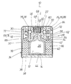
- FIG. 1 is a diagrammatic, sectional view of an activatable battery, which is taken along a first sectional plane;
- FIG. 2 is a sectional view of the activatable battery of FIG. 1 , which is taken along a sectional plane crossing the sectional plane of FIG. 1 .
- FIGS. 1 and 2 of the drawings there is seen a configuration of an activatable battery 10 for an electronic artillery fuse and mortar fuse.
- the battery 10 includes an ampoule 12 which has a bottom 14 , a side wall 16 extending away from the bottom 14 and a projection 18 .
- the ampoule 12 is filled with an electrolyte 20 .
- the battery 10 has an activation device 22 which can be released by a timing member 24 for evaluation of the duration of a force shock acting on the battery 10 , that is to say a mechanical impulse.
- the timing member 24 has an inertia body 26 which is axially and rotatably displaceable and against which a compression spring 28 is operative.
- the activatable battery 10 has an upper battery portion 30 and a lower battery portion 32 , which are disposed in such a way as to bear against each other in a cup-shaped housing 34 .
- a cup opening 36 of the cup-shaped housing 34 is closed sealingly by a cover element 38 .
- the ampoule 12 filled with the electrolyte 20 is disposed immovably in the lower battery portion 32 .
- the bottom 14 of the ampoule 12 bears against the cover element 38 of the cup-shaped housing 34 and its side wall 16 is fixed to an electrolyte-permeable ampoule receiving portion 40 of the lower battery portion 32 .
- the ampoule receiving portion 40 has internal dimensions which are matched without play to external dimensions of the side wall 16 of the ampoule 12 .
- the ampoule receiving portion 40 is also provided with a retaining shoulder 42 in order to axially immovably fix the ampoule 12 between the retaining shoulder 42 and the cover element 38 .
- the bottom 14 of the ampoule 12 is provided with an indentation 44 in order to reliably rupture the ampoule 12 at a given time.
- the projection 18 of the ampoule 12 which is remote from the bottom 14 , projects into the upper battery portion 30 .
- An ampoule striker 46 and a striker spring 48 of the activation device 22 are provided in the upper battery portion 30 .
- the ampoule striker 46 has a first end 50 , remote from the cover element 38 , with a central blind hole 52 in which the striker spring 48 is disposed.
- the striker spring 48 is formed by a mechanically prestressed compression coil spring.
- the ampoule striker 46 has a second end 54 , towards the cover element 38 , with a central recess 56 into which the projection 18 of the ampoule 12 projects with a slight spacing at all sides in an inactive storage condition.
- the upper battery portion 30 has a central space 58 for the ampoule striker 46 and for the striker spring 48 , as well as an annular space 62 , which is spaced from the central space 58 by a sleeve wall 60 and which is delimited externally by an annular flange 64 .
- the annular flange 64 is formed in one piece, with regard to the material involved, with the sleeve wall 60 , by way of an annular connecting portion 66 .
- the central space 58 of the upper battery portion 30 is closed at the top side by a cover 68 , which is formed in one piece with regard to the material involved.
- the sleeve wall 60 of the upper battery portion 30 has a number of through holes 70 which are uniformly distributed in the peripheral direction of the sleeve wall 60 .
- a locking ball 72 is disposed in each respective through hole 70 .
- the ampoule striker 46 has a recess 76 at its outer peripheral surface 74 adjacent the sleeve wall 60 .
- the recess 76 is in the form of a groove 78 , which extends around the outer peripheral surface 74 of the ampoule striker 46 .
- control pins 80 project from the annular flange 64 of the upper battery portion 30 into associated grooves 82 which are angled in a zig-zag shape and which are provided in an outer peripheral surface 84 of the inertia body 26 .
- grooves 82 which are angled in a zig-zag shape
- the inertia body 26 is in the form of an inertia ring 86 , which is displaceable under the effect of an impulse in the annular space 62 of the upper battery portion 30 , against the spring force of the compression spring 28 .
- the outer peripheral surface 84 of the inertia body 26 has a number, corresponding to the number of control pins 80 , of the grooves 82 which are angled in a zig-zag shape and which, like the control pins 80 , are spaced uniformly in the peripheral direction.
- the inertia ring 86 has a peripherally extending groove 90 at its end 88 towards the cover element 38 .
- the compression spring 28 is in the form of a compression coil spring and projects with one end portion 92 into the peripherally extending groove 90 in the inertia ring 86 .
- An oppositely disposed, other end portion 94 , of the compression coil spring 28 bears against the annular connecting portion 66 of the upper battery portion 30 .
- battery cells 96 Disposed in the lower battery portion 32 are battery cells 96 , which are spaced from the ampoule 12 by the electrolyte-permeable ampoule receiving portion 40 .
- the mode of operation of the activatable battery 10 is as follows:
- the inertia body 26 Due to firing or launch acceleration, the inertia body 26 is moved in the direction of the cover element 38 against the compression spring 28 . Due to the engagement of the control pins 80 into the grooves 82 which are provided in an angled configuration in a zig-zag shape in the outer peripheral surface 84 of the inertia body 26 , the movement of the inertia body 26 takes place not only in the axial direction in a straight line, but at the same time as the axial movement, the inertia body 26 must first rotate in one direction and thereafter in the opposite other direction in order to follow the path of movement of the inertia body 26 . That rotary movement and reversal is a timing member, as a consequence of the moment of inertia of the inertia body 26 .
- the firing or launch acceleration must be operative at a given level of magnitude over a given period of time, so that the inertia body 26 reaches its limit position.
- the ampoule striker 46 is released by way of the locking balls 72 . Due to the firing or launch acceleration which is still operative and/or due to the relief of the mechanically stressed striker spring 48 , the ampoule striker 46 is accelerated against the ampoule 12 which is fixedly installed in the lower battery portion 32 and which ruptures upon impact of the ampoule striker 46 against the projection 18 thereof and liberates the electrolyte 20 in the ampoule 12 .
- the ampoule striker 46 acts as a plunger. In a short time it presses the electrolyte 20 into the battery cells 96 . The electrolyte 20 therefore penetrates into the battery cells 96 so that the battery 10 very rapidly generates its electrical voltage.
- the ampoule 12 is immovably embedded in the lower battery portion 32 , it is afforded optimum protection in relation to any possible unintentional loading.
Landscapes
- Engineering & Computer Science (AREA)
- Manufacturing & Machinery (AREA)
- Chemical & Material Sciences (AREA)
- Chemical Kinetics & Catalysis (AREA)
- Electrochemistry (AREA)
- General Chemical & Material Sciences (AREA)
- Primary Cells (AREA)
- Secondary Cells (AREA)
- Battery Mounting, Suspending (AREA)
- Filling, Topping-Up Batteries (AREA)
Applications Claiming Priority (3)
| Application Number | Priority Date | Filing Date | Title |
|---|---|---|---|
| DE102006045953A DE102006045953B3 (de) | 2006-09-28 | 2006-09-28 | Aktivierbare Batterie für einen elektronischen Artilleriezünder |
| DE102006045953 | 2006-09-28 | ||
| DEDE102006045953.9 | 2006-09-28 |
Publications (2)
| Publication Number | Publication Date |
|---|---|
| US20080081248A1 US20080081248A1 (en) | 2008-04-03 |
| US8007934B2 true US8007934B2 (en) | 2011-08-30 |
Family
ID=38669900
Family Applications (1)
| Application Number | Title | Priority Date | Filing Date |
|---|---|---|---|
| US11/858,152 Active 2030-06-29 US8007934B2 (en) | 2006-09-28 | 2007-09-20 | Activatable battery for an electronic artillery fuse |
Country Status (5)
| Country | Link |
|---|---|
| US (1) | US8007934B2 (de) |
| EP (1) | EP1906475B1 (de) |
| AT (1) | ATE504096T1 (de) |
| DE (2) | DE102006045953B3 (de) |
| ZA (1) | ZA200708204B (de) |
Cited By (3)
| Publication number | Priority date | Publication date | Assignee | Title |
|---|---|---|---|---|
| US10746515B1 (en) | 2019-06-12 | 2020-08-18 | Insights International Holdings, Llc | Tracked synthetic ordnance |
| US11302930B2 (en) | 2018-06-29 | 2022-04-12 | Diehl & Eagle Picher Gmbh | Activation device for a battery for an electronic ignition mechanism and battery |
| US12272844B1 (en) * | 2023-05-10 | 2025-04-08 | The United States Of America As Represented By The Secretary Of The Army | Pressure activated battery system |
Families Citing this family (2)
| Publication number | Priority date | Publication date | Assignee | Title |
|---|---|---|---|---|
| DE102017002847B4 (de) * | 2017-03-23 | 2019-03-07 | Diehl & Eagle Picher Gmbh | Aktivierungseinrichtung für eine Batterie für einen elektronischen Zündmechanismus |
| CN113686213B (zh) * | 2021-07-19 | 2023-04-07 | 沈阳理工大学 | 一种微小型引信化学电源快速激活机构及其方法 |
Citations (6)
| Publication number | Priority date | Publication date | Assignee | Title |
|---|---|---|---|---|
| US3754996A (en) | 1972-06-28 | 1973-08-28 | Us Army | Ductile ampule deferred action battery |
| US4684586A (en) | 1986-12-01 | 1987-08-04 | Gte Government Systems Corporation | Electrochemical cell with interlocking anode |
| DE3718788A1 (de) | 1986-06-09 | 1987-12-10 | Tadiran Ltd | Reservebatterie |
| JPH10302811A (ja) | 1997-04-28 | 1998-11-13 | Matsushita Electric Ind Co Ltd | 注液式電池 |
| EP1178550A1 (de) | 2000-08-04 | 2002-02-06 | Junghans Feinwerktechnik GmbH & Co.KG | Aktivierbare Batterie für einen elektronischen Artilleriezünder |
| EP1467423A2 (de) | 2002-11-29 | 2004-10-13 | Thales Nederland B.V. | Reservebatterie und ihre Verwendung |
-
2006
- 2006-09-28 DE DE102006045953A patent/DE102006045953B3/de not_active Expired - Fee Related
-
2007
- 2007-09-05 DE DE502007006828T patent/DE502007006828D1/de active Active
- 2007-09-05 AT AT07017357T patent/ATE504096T1/de active
- 2007-09-05 EP EP07017357A patent/EP1906475B1/de active Active
- 2007-09-20 US US11/858,152 patent/US8007934B2/en active Active
- 2007-09-26 ZA ZA200708204A patent/ZA200708204B/en unknown
Patent Citations (9)
| Publication number | Priority date | Publication date | Assignee | Title |
|---|---|---|---|---|
| US3754996A (en) | 1972-06-28 | 1973-08-28 | Us Army | Ductile ampule deferred action battery |
| DE3718788A1 (de) | 1986-06-09 | 1987-12-10 | Tadiran Ltd | Reservebatterie |
| GB2192482A (en) | 1986-06-09 | 1988-01-13 | Tadiran Ltd | Reserve battery |
| US4684586A (en) | 1986-12-01 | 1987-08-04 | Gte Government Systems Corporation | Electrochemical cell with interlocking anode |
| JPH10302811A (ja) | 1997-04-28 | 1998-11-13 | Matsushita Electric Ind Co Ltd | 注液式電池 |
| EP1178550A1 (de) | 2000-08-04 | 2002-02-06 | Junghans Feinwerktechnik GmbH & Co.KG | Aktivierbare Batterie für einen elektronischen Artilleriezünder |
| US6673486B2 (en) | 2000-08-04 | 2004-01-06 | Junghans Feinwerktechnik Gmbh & Co. Kg | Timing mechanism for controlling the charging of a battery in an electronic artillery fuse |
| DE10038066B4 (de) | 2000-08-04 | 2004-07-08 | Junghans Feinwerktechnik Gmbh & Co. Kg | Aktivierbare Batterie für einen elektronischen Artilleriezünder |
| EP1467423A2 (de) | 2002-11-29 | 2004-10-13 | Thales Nederland B.V. | Reservebatterie und ihre Verwendung |
Cited By (3)
| Publication number | Priority date | Publication date | Assignee | Title |
|---|---|---|---|---|
| US11302930B2 (en) | 2018-06-29 | 2022-04-12 | Diehl & Eagle Picher Gmbh | Activation device for a battery for an electronic ignition mechanism and battery |
| US10746515B1 (en) | 2019-06-12 | 2020-08-18 | Insights International Holdings, Llc | Tracked synthetic ordnance |
| US12272844B1 (en) * | 2023-05-10 | 2025-04-08 | The United States Of America As Represented By The Secretary Of The Army | Pressure activated battery system |
Also Published As
| Publication number | Publication date |
|---|---|
| ZA200708204B (en) | 2008-10-29 |
| ATE504096T1 (de) | 2011-04-15 |
| EP1906475B1 (de) | 2011-03-30 |
| DE502007006828D1 (de) | 2011-05-12 |
| DE102006045953B3 (de) | 2008-06-12 |
| EP1906475A1 (de) | 2008-04-02 |
| US20080081248A1 (en) | 2008-04-03 |
Similar Documents
| Publication | Publication Date | Title |
|---|---|---|
| US12398990B2 (en) | Method for rotating a toggle link upon an acceleration event greater than a predetermined threshold | |
| US20080081248A1 (en) | Activatable Battery for an Electronic Artillery Fuse | |
| US8061271B2 (en) | Programmable inertial igniters for gun-fired munitions, thermal batteries and the like | |
| US8869700B2 (en) | Impulse-based compact mechanical G-switch with modular design | |
| EP2742293B1 (de) | High-g-trägheitszünder | |
| US12072174B2 (en) | Shear-pin based inertia igniters with preset no-fire protection for munitions and the like | |
| US6673486B2 (en) | Timing mechanism for controlling the charging of a battery in an electronic artillery fuse | |
| US20250052552A1 (en) | Actuation mechanism for actuating a device and method for actuating a device | |
| US10337848B2 (en) | Spin acceleration armed inertia igniters and electrical switches for munitions and the like | |
| US20140311369A1 (en) | Mechanical Inertial Igniter With High-Height Drop Safety Feature For Thermal Batteries and the Like | |
| US8651022B2 (en) | Compact mechanical inertia igniters for thermal batteries and the like | |
| US4637311A (en) | Method of, and apparatus for, increasing the energy in an electromagnetic fuze system | |
| US11592273B2 (en) | Torsion spring actuated inertia igniters and impulse switches with preset no-fire protection for munitions and the like | |
| US3858515A (en) | Projectile fuse | |
| US20240110774A1 (en) | Compact inertial igniters for munitions and the like with high-g shock protection | |
| US12007217B2 (en) | Compact inertial igniters and impulse switches with accidental activation prevention for munitions and the like | |
| US11302930B2 (en) | Activation device for a battery for an electronic ignition mechanism and battery | |
| US7055436B2 (en) | Shell fuse | |
| US6311622B1 (en) | Self-destruct fuze for munitions | |
| US12352550B2 (en) | Inertial igniters for low-G and long duration firing acceleration munitions and the like | |
| KR102488148B1 (ko) | 열전지 활성화 장치 및 이의 작동 방법 | |
| US20220412712A1 (en) | Lanyard actuated percussion primer ignition mechanism for reserve battery activation | |
| CN220230301U (zh) | 点火机构及具有其的功能弹头 | |
| CN119289801A (zh) | 一种低过载时序组合安全保险装置 | |
| WO2005093883A1 (en) | Reserve battery and its activation system |
Legal Events
| Date | Code | Title | Description |
|---|---|---|---|
| FEPP | Fee payment procedure |
Free format text: PAYOR NUMBER ASSIGNED (ORIGINAL EVENT CODE: ASPN); ENTITY STATUS OF PATENT OWNER: LARGE ENTITY |
|
| AS | Assignment |
Owner name: JUNGHANS MICROTEC GMBH, GERMANY Free format text: ASSIGNMENT OF ASSIGNORS INTEREST;ASSIGNORS:GLATTHAAR, KARL;HOENI, HERBERT;ZINELL, ALEXANDER;REEL/FRAME:026502/0911 Effective date: 20070827 |
|
| STCF | Information on status: patent grant |
Free format text: PATENTED CASE |
|
| FPAY | Fee payment |
Year of fee payment: 4 |
|
| MAFP | Maintenance fee payment |
Free format text: PAYMENT OF MAINTENANCE FEE, 8TH YEAR, LARGE ENTITY (ORIGINAL EVENT CODE: M1552); ENTITY STATUS OF PATENT OWNER: LARGE ENTITY Year of fee payment: 8 |
|
| MAFP | Maintenance fee payment |
Free format text: PAYMENT OF MAINTENANCE FEE, 12TH YEAR, LARGE ENTITY (ORIGINAL EVENT CODE: M1553); ENTITY STATUS OF PATENT OWNER: LARGE ENTITY Year of fee payment: 12 |