US8000646B2 - Image forming apparatus and image forming method - Google Patents
Image forming apparatus and image forming method Download PDFInfo
- Publication number
- US8000646B2 US8000646B2 US12/047,360 US4736008A US8000646B2 US 8000646 B2 US8000646 B2 US 8000646B2 US 4736008 A US4736008 A US 4736008A US 8000646 B2 US8000646 B2 US 8000646B2
- Authority
- US
- United States
- Prior art keywords
- paper
- continuous paper
- image
- width direction
- spacing
- Prior art date
- Legal status (The legal status is an assumption and is not a legal conclusion. Google has not performed a legal analysis and makes no representation as to the accuracy of the status listed.)
- Expired - Fee Related, expires
Links
Images


Classifications
-
- G—PHYSICS
- G03—PHOTOGRAPHY; CINEMATOGRAPHY; ANALOGOUS TECHNIQUES USING WAVES OTHER THAN OPTICAL WAVES; ELECTROGRAPHY; HOLOGRAPHY
- G03G—ELECTROGRAPHY; ELECTROPHOTOGRAPHY; MAGNETOGRAPHY
- G03G15/00—Apparatus for electrographic processes using a charge pattern
- G03G15/65—Apparatus which relate to the handling of copy material
- G03G15/6517—Apparatus for continuous web copy material of plain paper, e.g. supply rolls; Roll holders therefor
- G03G15/6526—Computer form folded [CFF] continuous web, e.g. having sprocket holes or perforations
-
- G—PHYSICS
- G03—PHOTOGRAPHY; CINEMATOGRAPHY; ANALOGOUS TECHNIQUES USING WAVES OTHER THAN OPTICAL WAVES; ELECTROGRAPHY; HOLOGRAPHY
- G03G—ELECTROGRAPHY; ELECTROPHOTOGRAPHY; MAGNETOGRAPHY
- G03G2215/00—Apparatus for electrophotographic processes
- G03G2215/00362—Apparatus for electrophotographic processes relating to the copy medium handling
- G03G2215/00443—Copy medium
- G03G2215/00451—Paper
- G03G2215/00455—Continuous web, i.e. roll
- G03G2215/00459—Fan fold, e.g. CFF, normally perforated
-
- G—PHYSICS
- G03—PHOTOGRAPHY; CINEMATOGRAPHY; ANALOGOUS TECHNIQUES USING WAVES OTHER THAN OPTICAL WAVES; ELECTROGRAPHY; HOLOGRAPHY
- G03G—ELECTROGRAPHY; ELECTROPHOTOGRAPHY; MAGNETOGRAPHY
- G03G2215/00—Apparatus for electrophotographic processes
- G03G2215/00362—Apparatus for electrophotographic processes relating to the copy medium handling
- G03G2215/00535—Stable handling of copy medium
- G03G2215/00717—Detection of physical properties
- G03G2215/00734—Detection of physical properties of sheet size
Definitions
- This invention relates to an image forming apparatus and an image forming method.
- an image forming apparatus including: an image transfer unit that transfers an image to continuous paper provided with a plurality of sprocket holes along a paper length direction on both sides in a paper width direction; an image fixing unit that fixes the image transported to the continuous paper by the image transfer unit; a transport unit that includes a plurality of protruding parts inserted into the sprocket holes on both sides in the paper width direction, that is placed downstream in a paper transport direction from the image fixing unit for moving the protruding parts in the paper transport direction, and that transports the continuous paper;
- control unit that controls drive of the change unit so that the spacing between the protruding parts in the paper width direction becomes narrower than the spacing between the sprocket holes in the continuous paper before image fixing in the paper width direction during image formation processing of the image transfer unit and the image fixing unit.
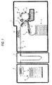
- FIG. 1 is a schematic drawing to show a configuration example of an image forming apparatus incorporating the invention
- FIG. 2 is a plan view to show a part of continuous paper
- FIG. 3 is a schematic diagram viewing the configuration of a tractor mechanism section included in a post-processing unit as a plane;
- FIG. 4 is a flowchart to show an example of control processing according to an embodiment of the invention.
- FIG. 5 is a drawing to show an example of a control table
- FIG. 6 is a developed plan view to show the positional relationship between sprocket holes in continuous paper and tractor pins
- FIG. 7 is a schematic diagram showing portions of the post processing unit.
- FIG. 8 is a schematic diagram showing the paper thickness detection sensor.
- FIG. 1 is a schematic drawing to show a configuration example of an image forming apparatus incorporating the invention.
- the image forming apparatus shown in the figure is roughly made up of an image printer 1 , a buffer 2 , and a post-processing unit 3 .
- the image printer 1 prints an image on continuous paper 4 ranging like a belt in accordance with electrophotography.
- the continuous paper 4 is provided with a plurality of sprocket holes H along a paper length direction Y on both sides in a paper width direction X, as shown in FIG. 2 .
- the sprocket holes H are formed continuously at given spacings in the paper length direction Y. Spacing P between the sprocket holes H in the paper width direction X is set to a dimension smaller than the width of the continuous paper 4 .
- the image printer 1 includes a hopper section 5 for storing continuous paper 4 before image formation in a stack state, two tractor mechanism sections 6 and 7 for transporting the continuous paper 4 stored in the hopper section 5 , a roll pair 8 for drawing the continuous paper 4 into the buffer 2 , an image transfer section 9 for transferring a toner image to the continuous paper 4 , and an image fixing unit 10 for fixing the toner image onto the continuous paper 4 .
- the hopper section 5 stores the continuous paper 4 folded like a letter Z.
- the tractor mechanism section 6 is placed upstream in the paper transport direction from the image transfer section 9 , and the tractor mechanism section 7 is placed downstream in the paper transport direction from the image transfer section 9 .
- the roll pair 8 rotates with the continuous paper 4 sandwiched between the rolls, thereby drawing the continuous paper 4 downstream in the paper transport direction.
- the image transfer section 9 has a photoconductor drum 11 , a charger 12 , a laser exposure device 13 , a developing device 14 , a transfer roll 15 , and a drum cleaner 16 .
- the photoconductor drum 11 is rotated clockwise in the figure at given speed.
- the charger 12 charges the surface of the photoconductor drum 11 at a uniform potential.
- the laser exposure device 13 scans a laser beam over the surface of the photoconductor drum 11 , thereby forming an electrostatic latent image on the surface of the photoconductor drum 11 .
- the developing device 14 uses toner to develop the electrostatic latent image formed on the surface of the photoconductor drum 11 by the laser exposure device 13 .
- the transfer roll 15 transfers the toner image developed by the developing device 14 to the continuous paper 4 .
- the drum cleaner 16 removes toner remaining on the surface of the photoconductor drum 11 after the transfer with a brush, a blade, etc., for example.
- the image fixing unit 10 is implemented as a flash fixing unit for fixing the toner image transferred to the continuous paper 4 by the image transfer section 9 onto the continuous paper 4 by heat energy of flash light, for example.
- the image fixing unit 10 is placed downstream in the paper transport direction from the tractor mechanism section 7 and upstream in the paper transport direction from the roll pair 8 .
- a transport guide 17 is provided downstream from the tractor mechanism section 6 . It guides the continuous paper 4 transported by the tractor mechanism sections 6 and 7 toward an opposed position between the photoconductor drum 11 and the transfer roll 15 (position at which the toner image is transferred to the continuous paper 4 ).
- the buffer 2 transfers the continuous paper 4 from the image printer 1 to the post-processing unit 3 while absorbing the processing speed difference between the image printer 1 and the post-processing unit 3 .
- the post-processing unit 3 performs post-processing for the continuous paper 4 delivered from the buffer 2 with image print (formation) on the continuous paper 4 completed on the image printer 1 .
- the post-processing unit 3 has a tractor mechanism section 18 for transporting the continuous paper 4 , a handling section 20 (shown in FIG. 7 ) for performing predetermined post-processing for the continuous paper 4 transported with the tractor mechanism section 18 , for example, cutting the continuous paper 4 to a predetermined length, and a stacker section 19 for storing the paper subjected to post-processing in the handling section 20 in a stack state.
- the pin tractor system is a system of transporting continuous paper by providing a plurality of tractor pins on the outer peripheral surface of a tractor belt stretched like a loop shape and running the tractor belt in a peripheral length direction in a state in which the tractor pins are inserted into the sprocket holes of the continuous paper.
- the pin tractor system continuous paper is pressed by a tractor cover with the sprocket holes inserted into the tractor pins, whereby the sprocket holes of the continuous paper are prevented from getting out of the tractor pins.
- continuous paper 4 drawn out from the hopper section 5 is transported in the paper transport direction by driving the tractor mechanism section 6 and driving the tractor mechanism section 7 in synchronization with driving the tractor mechanism section 6 , and a toner image is transferred to the continuous paper 4 by the image transfer section 9 at a midpoint in the transport.
- the continuous paper 4 to which the toner image is thus transferred is drawn downstream in the paper transport direction by the roll pair 8 and meanwhile the toner image is fixed onto the continuous paper 4 by the image fixing unit 10 .
- the continuous paper 4 is shrunk by heat applied by the image fixing unit 10 .
- the continuous paper 4 with an image already fixed thereon, delivered from the image printer 1 is transported to the post-processing unit 3 .
- the continuous paper 4 delivered from the buffer 2 is transported in the paper transport direction by driving the tractor mechanism section 18 and is also cut to a predetermined length by the handling section 20 (shown in FIG. 7 ) and then the paper is stored in the stacker section 19 .
- FIG. 3 is a schematic diagram viewing the configuration of the tractor mechanism section 18 included in the post-processing unit 3 as a plane.
- the tractor mechanism section 18 is provided as transport unit. It is provided with two tractor belts 21 and 22 .
- Each of the tractor belts 21 and 22 is stretched like a loop shape between a pair of pulleys (not shown) viewed from the paper width direction orthogonal to the paper transport direction.
- the pair of pulleys is rotated by a transport motor (not shown) with one pulley as a driving pulley and the other as a driven pulley.
- a plurality of tractor pins 23 as protruding parts are provided on the outer peripheral portion of the tractor belt 21 and a plurality of tractor pins 24 as protruding parts are also provided on the outer peripheral portion of the tractor belt 22 .
- the spacings of the tractor pins 23 in the paper transport direction and the spacings of the tractor pins 24 in the paper transport direction are set to the same as the spacings of the sprocket holes H in the paper length direction Y shown in FIG. 2 .
- Two (a pair of) shafts 27 A and 28 B are placed between frame members 25 and 26 opposed to each other in the paper width direction.
- the shafts 27 A and 28 B are placed in parallel with each other in the direction orthogonal to the paper transport direction.
- a ball screw 28 is placed between the shafts 27 A and 28 B.
- the ball screw 28 has a spiral groove on the outer peripheral portion. It is placed in parallel with the shafts 27 A and 28 B.
- the ball screw 28 is supported for rotation using bearing members, etc., in the frame members 25 and 26 .
- a nut member 29 meshing with the spiral groove is attached to the ball screw 28 .
- the nut member 29 is joined to a support member (not shown) provided so as to be movable in the paper width direction with a screw, etc.
- the support member moves in the paper width direction together with the above-mentioned pair of pulleys (not shown) for supporting the tractor belt 22 like a loop shape.
- the tractor belt 22 moves in the paper width direction in one piece with the nut member 29 in response to the rotation amount and the rotation direction of the ball screw 28 .
- a motor 32 is attached to the frame member 25 with a motor attachment member 31 . It is electrically connected to a control section 33 for controlling drive of the motor 32 .
- the control section 33 supplies a drive pulse to the motor 32 , thereby controlling drive of the motor 32 (rotation amount, rotation direction, etc.,).
- any other motor than the pulse motor such as a DC servo motor, may be used as the motor 32 and a rotary encode may be attached to the DC servo motor for controlling drive of the motor 32 .
- a gear 34 is attached to a rotation shaft of the motor 32 . It rotates in accordance with drive of the motor 32 .
- the gear 34 meshes with the gear 30 .
- the gears 30 and 34 make up a power transmission mechanism for transmitting the rotation drive force of the motor 32 to the ball screw 28 .
- the tractor mechanism section 18 includes change unit for changing the spacing between the tractor pins 23 and 24 in the paper width direction.
- one tractor belt 21 is fixed and the other tractor belt 22 is movable in the paper width direction.
- one tractor belt 21 may be movable and the other tractor belt 22 may be fixed.
- Both the tractor belts 21 and 22 may be movable by joining a nut member also to one tractor belt 21 in a similar manner to that described above.
- the threading direction of the nut member corresponding to one tractor belt 21 and that of the nut member corresponding to the other tractor belt 22 are opposed to each other and if the two tractor belts 21 and 22 are allowed to move toward or away from each other in the same amount in the paper width direction when the common ball screw 28 with which the nut members mesh is rotated, the center position in the paper width direction does not shift between the tractor pins 23 and 24 even if the spacing between the tractor pins 23 and 24 is changed.
- FIG. 4 is a flowchart to show an example of control processing executed by the control section 33 in the image forming apparatus according to the embodiment of the invention.
- the sprocket holes H made in the continuous paper 4 are fitted into the tractor pins of the tractor mechanism sections 6 , 7 , and 18 in the paper transport passage from the image printer 1 via the buffer 2 to the post-processing unit 3 .
- the spacing between the tractor pins in the paper width direction is set to the same as the spacing P between the sprocket holes H in the continuous paper 4 ( FIG. 2 ).
- the control section 33 drives the motor 32 provided in the tractor mechanism section 18 in the post-processing unit 3 , thereby changing so that the spacing between the tractor pins 23 and 24 in the paper width direction (which will be hereinafter also referred to as “pin spacing”) becomes narrower by a given amount than the spacing P between the sprocket holes H in the continuous paper 4 before image fixing in the paper width direction (which will be hereinafter also referred to as “hole spacing”) (steps S 1 and S 2 ).
- the continuous paper 4 before image fixing is used to mean the continuous paper 4 before image fixing is performed in the image fixing unit 10 of the image printer 1 . Therefore, the continuous paper 4 stacked in the hopper section 5 and the continuous paper 4 drawn out from the hopper section 5 and placed upstream from the image fixing unit 10 correspond each to the continuous paper 4 before image fixing.
- control section 33 drives the motor 32 at step S 2 , it references a control table previously stored in nonvolatile memory, etc., for example.
- the types of continuous paper 4 and the change amounts of the pin spacing are previously associated with each other in the control table referenced by the control section 33 .
- the types of continuous paper 4 are classified according to the thickness of the continuous paper 4 (cardboard, ordinary paper, thin paper) and the change amounts of the pin spacing, ⁇ P 1 , ⁇ P 2 , and ⁇ P 3 , are preset in association with the paper thicknesses, as shown in FIG. 5 .
- control section 33 references the control table, if the continuous paper 4 is “cardboard,” the motor 32 is driven so as to narrow the spacing between the tractor pins 23 and 24 in the paper width direction by ⁇ P 1 ; if the continuous paper 4 is “ordinary paper,” the motor 32 is driven so as to narrow the spacing between the tractor pins 23 and 24 in the paper width direction by ⁇ P 2 ; and if the continuous paper 4 is “thin paper,” the motor 32 is driven so as to narrow the spacing between the tractor pins 23 and 24 in the paper width direction by ⁇ P 3 .
- the paper shrink amount of thin paper becomes larger than that of thick paper.
- the change amounts of the pin spacing, ⁇ P 1 , ⁇ P 2 , and ⁇ P 3 are associated with the thicknesses of continuous paper 4 in the relation of ⁇ P 1 ⁇ P 2 ⁇ P 3 .
- the control section 33 may recognize the thickness of continuous paper 4 based on paper information entered by the operator using the operation panel, etc., or a paper thickness detection sensor 50 (shown in FIG. 8 ) may be provided downstream in the paper transport direction from the image fixing unit 10 so that the control section 33 recognizes the thickness of continuous paper 4 based on the detection result of the paper thickness detection sensor 50 .
- the paper thickness detection sensor 50 may be implemented as a transmission photosensor for detecting the paper thickness according to the light transmittance difference responsive to the paper thickness, a magnetic angle sensor for detecting the paper thickness according to the lever inclination angle difference responsive to the paper thickness, or the like.
- control section 33 determines whether or not the print processing (image formation processing) in the image printer 1 terminates (step S 3 ). If the control section 33 determines that the print processing in the image printer 1 terminates, it goes to step S 7 and drives the motor 32 of the tractor mechanism section 18 under the condition that the pin spacing becomes the same as the hole spacing, thereby restoring the pin spacing to the former pin spacing, and then terminates the processing sequence.
- control section 33 determines that the print processing in the image printer 1 terminates. If a paper-out condition does not occur, the control section 33 returns to step S 3 . If a paper-out condition occurs before the print processing terminates, the control section 33 stops the whole processing operation of the image forming apparatus (step 5 ) and displays an alarm to inform the operator that a paper-out condition has occurred (step S 6 ). Then, the control section 33 goes to step S 7 and drives the motor 32 of the tractor mechanism section 18 under the condition that the pin spacing becomes the same as the hole spacing, thereby restoring the pin spacing to the former pin spacing.
- the control processing as described above is applied, whereby when the toner image transferred to the continuous paper 4 in the image transfer section 9 is thermally fixed in the image fixing unit 10 , if the hole spacing in the continuous paper 4 after the image fixing becomes narrow from P to P′ as compared with that in the continuous paper 4 before the image fixing as shown in FIG. 6 because of the effect of shrink of the continuous paper 4 caused by the thermal fixing, change is made so as to narrow the pin spacing of the tractor mechanism section 18 accordingly, whereby the shift between the hole spacing in the continuous paper 4 and the pin spacing lessens as compared with the case where the pin spacing is not changed.
- the tractor pins 23 and 24 of the tractor mechanism section 18 become hard to get out of the sprocket holes H of the continuous paper 4 in the post-processing unit 3 .
- the types of continuous paper 4 are classified according to the paper thickness; in addition, the types of continuous paper 4 may be classified according to the paper quality (woodfree paper, wood containing paper, etc.,), for example.
- the operator may use the operation panel, etc., to enter the correspondence between the types of continuous paper 4 and the change amounts of the pin spacing in the control table referenced by the control section 33 .
- the image fixing unit is not limited to the image fixing unit of flash fixing type and may be an image fixing unit using a heat roll.
- the invention is applied to an electrophotographic image forming apparatus having transport unit of pin tractor system downstream in the paper transport direction from the image fixing unit.
Landscapes
- Engineering & Computer Science (AREA)
- General Engineering & Computer Science (AREA)
- Physics & Mathematics (AREA)
- General Physics & Mathematics (AREA)
- Advancing Webs (AREA)
- Handling Of Sheets (AREA)
- Control Or Security For Electrophotography (AREA)
Abstract
Description
Claims (12)
Applications Claiming Priority (2)
| Application Number | Priority Date | Filing Date | Title |
|---|---|---|---|
| JP2007-065096 | 2007-03-14 | ||
| JP2007065096A JP2008225193A (en) | 2007-03-14 | 2007-03-14 | Image forming apparatus |
Publications (2)
| Publication Number | Publication Date |
|---|---|
| US20080226999A1 US20080226999A1 (en) | 2008-09-18 |
| US8000646B2 true US8000646B2 (en) | 2011-08-16 |
Family
ID=39763037
Family Applications (1)
| Application Number | Title | Priority Date | Filing Date |
|---|---|---|---|
| US12/047,360 Expired - Fee Related US8000646B2 (en) | 2007-03-14 | 2008-03-13 | Image forming apparatus and image forming method |
Country Status (2)
| Country | Link |
|---|---|
| US (1) | US8000646B2 (en) |
| JP (1) | JP2008225193A (en) |
Families Citing this family (2)
| Publication number | Priority date | Publication date | Assignee | Title |
|---|---|---|---|---|
| JP5728876B2 (en) * | 2010-10-08 | 2015-06-03 | セイコーエプソン株式会社 | Printing device |
| JP7224893B2 (en) * | 2018-12-19 | 2023-02-20 | キヤノン株式会社 | Method for manufacturing pressure device and method for manufacturing image forming apparatus |
Citations (12)
| Publication number | Priority date | Publication date | Assignee | Title |
|---|---|---|---|---|
| US4619389A (en) * | 1984-05-02 | 1986-10-28 | Oki Electric Industry Co., Ltd. | Paper tractor |
| US4786353A (en) * | 1987-10-16 | 1988-11-22 | Adolph Coors Company | Laminating method and apparatus with extensible web width control |
| US4839814A (en) * | 1985-01-29 | 1989-06-13 | Moore Business Forms, Inc. | Size independent modular web processing line and modules |
| US5189470A (en) * | 1990-10-03 | 1993-02-23 | Kabushiki Kaisha Sato | Xerographic apparatus for label printer |
| JPH0561984A (en) * | 1991-09-03 | 1993-03-12 | Nikon Corp | Digraph display device |
| US5217312A (en) * | 1992-05-19 | 1993-06-08 | Lexmark International, Inc. | Single lever push/pull/park selector for printer forms tractor |
| JPH0692534A (en) | 1992-09-16 | 1994-04-05 | Fujitsu Ltd | Continuous paper printer |
| US5713674A (en) * | 1994-10-06 | 1998-02-03 | Pfu Limited | Paper feed method and apparatus for a printer |
| US5765460A (en) * | 1995-12-18 | 1998-06-16 | Wathieu; Patrick | Paper cutter for variable format |
| JPH11240213A (en) * | 1998-02-26 | 1999-09-07 | Nec Off Syst Ltd | Printer device |
| US6718150B2 (en) * | 2001-12-19 | 2004-04-06 | Fuji Xerox Co., Ltd. | Image forming apparatus and image forming method |
| US7284486B2 (en) * | 2002-10-11 | 2007-10-23 | Oce Printing Systems Gmbh | Device and method for controlling the position of the lateral edge of a continuous web |
Family Cites Families (4)
| Publication number | Priority date | Publication date | Assignee | Title |
|---|---|---|---|---|
| JPS6164480A (en) * | 1984-09-07 | 1986-04-02 | Kanzaki Paper Mfg Co Ltd | Thermal printer |
| JP2004029563A (en) * | 2002-06-27 | 2004-01-29 | Sharp Corp | Fixing device and image forming device |
| JP2006076013A (en) * | 2004-09-07 | 2006-03-23 | Ricoh Printing Systems Ltd | Printer |
| JP2006251371A (en) * | 2005-03-10 | 2006-09-21 | Ricoh Co Ltd | Image forming apparatus |
-
2007
- 2007-03-14 JP JP2007065096A patent/JP2008225193A/en active Pending
-
2008
- 2008-03-13 US US12/047,360 patent/US8000646B2/en not_active Expired - Fee Related
Patent Citations (12)
| Publication number | Priority date | Publication date | Assignee | Title |
|---|---|---|---|---|
| US4619389A (en) * | 1984-05-02 | 1986-10-28 | Oki Electric Industry Co., Ltd. | Paper tractor |
| US4839814A (en) * | 1985-01-29 | 1989-06-13 | Moore Business Forms, Inc. | Size independent modular web processing line and modules |
| US4786353A (en) * | 1987-10-16 | 1988-11-22 | Adolph Coors Company | Laminating method and apparatus with extensible web width control |
| US5189470A (en) * | 1990-10-03 | 1993-02-23 | Kabushiki Kaisha Sato | Xerographic apparatus for label printer |
| JPH0561984A (en) * | 1991-09-03 | 1993-03-12 | Nikon Corp | Digraph display device |
| US5217312A (en) * | 1992-05-19 | 1993-06-08 | Lexmark International, Inc. | Single lever push/pull/park selector for printer forms tractor |
| JPH0692534A (en) | 1992-09-16 | 1994-04-05 | Fujitsu Ltd | Continuous paper printer |
| US5713674A (en) * | 1994-10-06 | 1998-02-03 | Pfu Limited | Paper feed method and apparatus for a printer |
| US5765460A (en) * | 1995-12-18 | 1998-06-16 | Wathieu; Patrick | Paper cutter for variable format |
| JPH11240213A (en) * | 1998-02-26 | 1999-09-07 | Nec Off Syst Ltd | Printer device |
| US6718150B2 (en) * | 2001-12-19 | 2004-04-06 | Fuji Xerox Co., Ltd. | Image forming apparatus and image forming method |
| US7284486B2 (en) * | 2002-10-11 | 2007-10-23 | Oce Printing Systems Gmbh | Device and method for controlling the position of the lateral edge of a continuous web |
Also Published As
| Publication number | Publication date |
|---|---|
| US20080226999A1 (en) | 2008-09-18 |
| JP2008225193A (en) | 2008-09-25 |
Similar Documents
| Publication | Publication Date | Title |
|---|---|---|
| JP5865872B2 (en) | Image forming apparatus | |
| JP5232838B2 (en) | Drive mechanism and image forming apparatus having the same | |
| JP5102449B2 (en) | Paper folding apparatus and image forming apparatus | |
| JP5135189B2 (en) | Image forming apparatus | |
| JP5815589B2 (en) | Recording medium feeding unit and image forming apparatus having the same | |
| JP2001335206A (en) | Printing equipment | |
| US8000646B2 (en) | Image forming apparatus and image forming method | |
| JP5325758B2 (en) | Sheet supply apparatus and image forming apparatus | |
| JP5984756B2 (en) | Image forming apparatus | |
| JP4025732B2 (en) | Medium transport device | |
| US7046953B2 (en) | Image formation apparatus equipped with automatic document feeder | |
| JP6937991B2 (en) | Feeding device and image forming device | |
| JP3261095B2 (en) | Sheet conveying device and image forming apparatus provided with the sheet conveying device | |
| JP2007021927A (en) | Image recording device | |
| JP4511586B2 (en) | Image forming apparatus | |
| JP2010083644A (en) | Sheet detecting device and image forming device | |
| JP2002293463A (en) | Paper carrying mechanism for image recording device | |
| JP6669989B2 (en) | Paper feeder and image forming apparatus | |
| JP6699431B2 (en) | Paper transport device and image forming device | |
| JP6249107B2 (en) | Sheet post-processing apparatus and image forming system including the same | |
| JP3406996B2 (en) | Image forming device | |
| JP7749997B2 (en) | Processing device and image forming system | |
| JP2897605B2 (en) | Paper handling equipment | |
| JP2011113046A (en) | Fixing device and image forming apparatus including the same | |
| JP2007168396A (en) | Image formation apparatus |
Legal Events
| Date | Code | Title | Description |
|---|---|---|---|
| AS | Assignment |
Owner name: FUJI XEROX CO., LTD., JAPAN Free format text: ASSIGNMENT OF ASSIGNORS INTEREST;ASSIGNOR:HIRAO, NAOTO;REEL/FRAME:020643/0659 Effective date: 20080307 |
|
| ZAAA | Notice of allowance and fees due |
Free format text: ORIGINAL CODE: NOA |
|
| ZAAB | Notice of allowance mailed |
Free format text: ORIGINAL CODE: MN/=. |
|
| STCF | Information on status: patent grant |
Free format text: PATENTED CASE |
|
| FPAY | Fee payment |
Year of fee payment: 4 |
|
| MAFP | Maintenance fee payment |
Free format text: PAYMENT OF MAINTENANCE FEE, 8TH YEAR, LARGE ENTITY (ORIGINAL EVENT CODE: M1552); ENTITY STATUS OF PATENT OWNER: LARGE ENTITY Year of fee payment: 8 |
|
| AS | Assignment |
Owner name: FUJIFILM BUSINESS INNOVATION CORP., JAPAN Free format text: CHANGE OF NAME;ASSIGNOR:FUJI XEROX CO., LTD.;REEL/FRAME:058287/0056 Effective date: 20210401 |
|
| FEPP | Fee payment procedure |
Free format text: MAINTENANCE FEE REMINDER MAILED (ORIGINAL EVENT CODE: REM.); ENTITY STATUS OF PATENT OWNER: LARGE ENTITY |
|
| LAPS | Lapse for failure to pay maintenance fees |
Free format text: PATENT EXPIRED FOR FAILURE TO PAY MAINTENANCE FEES (ORIGINAL EVENT CODE: EXP.); ENTITY STATUS OF PATENT OWNER: LARGE ENTITY |
|
| STCH | Information on status: patent discontinuation |
Free format text: PATENT EXPIRED DUE TO NONPAYMENT OF MAINTENANCE FEES UNDER 37 CFR 1.362 |
|
| FP | Lapsed due to failure to pay maintenance fee |
Effective date: 20230816 |