US7959159B2 - Sealing arrangement - Google Patents
Sealing arrangement Download PDFInfo
- Publication number
- US7959159B2 US7959159B2 US11/903,341 US90334107A US7959159B2 US 7959159 B2 US7959159 B2 US 7959159B2 US 90334107 A US90334107 A US 90334107A US 7959159 B2 US7959159 B2 US 7959159B2
- Authority
- US
- United States
- Prior art keywords
- sealing
- seal arrangement
- accordance
- dynamic
- sealing element
- Prior art date
- Legal status (The legal status is an assumption and is not a legal conclusion. Google has not performed a legal analysis and makes no representation as to the accuracy of the status listed.)
- Active, expires
Links
Images


Classifications
-
- F—MECHANICAL ENGINEERING; LIGHTING; HEATING; WEAPONS; BLASTING
- F16—ENGINEERING ELEMENTS AND UNITS; GENERAL MEASURES FOR PRODUCING AND MAINTAINING EFFECTIVE FUNCTIONING OF MACHINES OR INSTALLATIONS; THERMAL INSULATION IN GENERAL
- F16J—PISTONS; CYLINDERS; SEALINGS
- F16J15/00—Sealings
- F16J15/16—Sealings between relatively-moving surfaces
- F16J15/32—Sealings between relatively-moving surfaces with elastic sealings, e.g. O-rings
- F16J15/3204—Sealings between relatively-moving surfaces with elastic sealings, e.g. O-rings with at least one lip
- F16J15/3208—Sealings between relatively-moving surfaces with elastic sealings, e.g. O-rings with at least one lip provided with tension elements, e.g. elastic rings
- F16J15/3212—Sealings between relatively-moving surfaces with elastic sealings, e.g. O-rings with at least one lip provided with tension elements, e.g. elastic rings with metal springs
-
- F—MECHANICAL ENGINEERING; LIGHTING; HEATING; WEAPONS; BLASTING
- F02—COMBUSTION ENGINES; HOT-GAS OR COMBUSTION-PRODUCT ENGINE PLANTS
- F02M—SUPPLYING COMBUSTION ENGINES IN GENERAL WITH COMBUSTIBLE MIXTURES OR CONSTITUENTS THEREOF
- F02M59/00—Pumps specially adapted for fuel-injection and not provided for in groups F02M39/00 -F02M57/00, e.g. rotary cylinder-block type of pumps
- F02M59/44—Details, components parts, or accessories not provided for in, or of interest apart from, the apparatus of groups F02M59/02 - F02M59/42; Pumps having transducers, e.g. to measure displacement of pump rack or piston
- F02M59/442—Details, components parts, or accessories not provided for in, or of interest apart from, the apparatus of groups F02M59/02 - F02M59/42; Pumps having transducers, e.g. to measure displacement of pump rack or piston means preventing fuel leakage around pump plunger, e.g. fluid barriers
-
- F—MECHANICAL ENGINEERING; LIGHTING; HEATING; WEAPONS; BLASTING
- F16—ENGINEERING ELEMENTS AND UNITS; GENERAL MEASURES FOR PRODUCING AND MAINTAINING EFFECTIVE FUNCTIONING OF MACHINES OR INSTALLATIONS; THERMAL INSULATION IN GENERAL
- F16J—PISTONS; CYLINDERS; SEALINGS
- F16J15/00—Sealings
- F16J15/16—Sealings between relatively-moving surfaces
- F16J15/32—Sealings between relatively-moving surfaces with elastic sealings, e.g. O-rings
- F16J15/3204—Sealings between relatively-moving surfaces with elastic sealings, e.g. O-rings with at least one lip
- F16J15/3232—Sealings between relatively-moving surfaces with elastic sealings, e.g. O-rings with at least one lip having two or more lips
- F16J15/3236—Sealings between relatively-moving surfaces with elastic sealings, e.g. O-rings with at least one lip having two or more lips with at least one lip for each surface, e.g. U-cup packings
-
- F—MECHANICAL ENGINEERING; LIGHTING; HEATING; WEAPONS; BLASTING
- F02—COMBUSTION ENGINES; HOT-GAS OR COMBUSTION-PRODUCT ENGINE PLANTS
- F02M—SUPPLYING COMBUSTION ENGINES IN GENERAL WITH COMBUSTIBLE MIXTURES OR CONSTITUENTS THEREOF
- F02M2200/00—Details of fuel-injection apparatus, not otherwise provided for
- F02M2200/16—Sealing of fuel injection apparatus not otherwise provided for
Definitions
- the present invention relates to a seal arrangement for sealing between a first medium space filled with a first medium and a second medium space filled with a second medium, wherein a moveable component which is displaceable in the longitudinal direction thereof and/or rotatable about the longitudinal direction thereof extends through the seal arrangement and wherein the seal arrangement comprises a sealing element which comprises a first sealing region that is sealing in relation to the first medium space and a second sealing region that is sealing in relation to the second medium space,
- first sealing region comprises a first dynamic sealing section abutting against the moveable component and the second sealing region comprises a second dynamic sealing section abutting against the moveable component and at least one of the two dynamic sealing sections has at least two sealing lips.
- a seal arrangement for the purposes of sealing the piston of a high-pressure pump used for the direct injection of petrol into the cylinders of an Otto engine, wherein the sealing element of said seal arrangement comprises a first dynamic sealing section with two sealing lips for sealing in relation to the petrol side of the system and a second dynamic sealing section with a memory sealing lip for sealing in relation to the engine oil side of the system.
- the object of the present invention is to produce a seal arrangement of the type mentioned hereinabove which ensures reliable sealing between the medium spaces whilst exhibiting very low leakage values over a longer period of use.
- each of the two sealing regions comprises at least one respective spring element which biases the dynamic sealing section of the respective sealing region against the moveable component.
- the first and/or the second medium is preferably a liquid.
- the first medium and the second medium can be of mutually differing liquids.
- one has at least two sealing lips whilst the respective other one has at least one sealing lip.
- both dynamic sealing sections to each have at least two sealing lips.
- a still better sealing effect is obtained if at least one of the dynamic sealing sections has at least three sealing lips.
- both dynamic sealing sections each have at least three sealing lips.
- the sealing element is preferably ring-shaped and in particular, it is formed such as to be rotationally symmetrical with respect to the longitudinal direction of the moveable component.
- the sealing element In order to enable the sealing element to be inserted into the seal arrangement in both a starting position and in a position rotated through 180° with respect to the starting position, provision is preferably made for the sealing element to be formed such that it is substantially mirror-symmetrical with respect to a transverse central plane of the sealing element running perpendicularly to the longitudinal direction of the moveable component.
- the assembly of the seal arrangement is substantially simplified in this way.
- the sealing element comprises a central web which is arranged between the first dynamic sealing section and the second dynamic sealing section and abuts against the moveable component in the installed state of the seal arrangement.
- the first sealing region in accordance with the invention, provision is made for the first sealing region to comprise a first static sealing section arranged radially outwardly from the first dynamic sealing section.
- the second sealing region comprises a second static sealing section arranged radially outwardly from the second dynamic sealing section.
- the first static sealing section and the second static sealing section preferably abut in sealing manner on a seal carrier into which the sealing element is inserted.
- the static sealing sections may extend in the axial direction of the sealing element, i.e. in a direction running parallel to the longitudinal direction of the moveable component, to substantially the same extent as the appertaining dynamic sealing sections.
- the axial ends of the static sealing sections may be located at the same distance from a transverse central plane of the sealing element as the axial ends of the dynamic sealing sections.
- At least one static sealing section of the sealing element can be supported in the axial direction on a seal carrier or on another component of the seal arrangement.
- the sealing element of the seal arrangement in accordance with the invention advantageously comprises a fluoropolymer material.
- the sealing element may comprise a polytetrafluoroethylene (PTFE) or a modified polytetrafluoroethylene.
- PTFE polytetrafluoroethylene
- a “modified polytetrafluoroethylene” is to be understood as being a substance similar to PTFE wherein the molecular structure of the PTFE has been chemically modified in that yet another likewise perfluoridated monomer has been built into the molecular chain in addition to the tetrafluoroethylene so that the fluorine atoms of the PTFE are partially replaced by substituents.
- Such PTFE containing materials exhibit particularly good temperature and chemical resistances as well as good dry-running properties.
- the sealing element can consist of polytetrafluoroethylene or of a modified polytetrafluoroethylene.
- the sealing element may also be made for the sealing element to be formed from a polytetrafluoroethylene compound or from a modified polytetrafluoroethylene compound, i.e. from a mixture of a polytetrafluoroethylene or a modified polytetrafluoroethylene with one or more organic or inorganic fillers.
- At least one dynamic sealing section of the sealing element has at least one leakage storage space which is formed between two neighbouring sealing lips of the dynamic sealing section concerned.
- Such a leakage storage space is preferably ring-shaped.
- At least one dynamic sealing section of the sealing element has a plurality of leakage storage spaces which succeed one another in the longitudinal direction of the moveable component.
- the leakage storage spaces of the dynamic sealing section may be of different sizes in order to allow for the fact that the amount of leakage decreases from the axial ends of the sealing element towards the centre of the sealing element since the leakage media must pass an increasing number of sealing lips in order to approach the centre of the sealing element.
- Leakage storage spaces of different sizes can be produced for example, in that the sealing lips which bound the leakage storage spaces are of different internal diameters in the manufacturing state of the sealing element.
- these sealing lips are then deformed in such a way that they have an internal diameter corresponding to the external diameter of the moveable component so that, in operation of the seal arrangement, the sealing lips abut in sealing manner against the sealing surface of the moveable component.
- At least one sealing lip of the sealing element is preferably designed in such a way that it has two boundary surfaces which are inclined at different angles ( ⁇ , ⁇ ) with respect to a plane running perpendicularly to the longitudinal direction of the moveable component.
- That boundary surface which is oriented towards the nearest medium-space end of the sealing element is inclined at a smaller angle (a) with respect to the plane running perpendicularly to the longitudinal direction of the moveable component than that boundary surface which is oriented in the direction away from the nearest medium-space end of the sealing element.
- the effect achieved by this design of the sealing lip is that the leakage medium can only overcome the sealing lip with difficulty in a direction away from a medium-space end of the sealing element, but can easily be dragged back towards a medium-space end of the sealing element in the opposite direction.
- the sealing lips of the sealing element of the seal arrangement in accordance with the invention may comprise sharply delimited sealing edges which abut against a sealing surface of the moveable component along a single line.
- At least one dynamic sealing section of the sealing element may also be made for at least one dynamic sealing section of the sealing element to have at least one flattened sealing lip which is supported on the moveable component in the installed state of the seal arrangement by means of a supporting surface aligned substantially in parallel with the longitudinal direction of the moveable component. Due to this supporting surface which is of greater space compared with a sharp sealing lip, the specific surface pressure on the sealing lip concerned is decreased and the bearing portion of the sealing lip is increased when new, whereby wear of the sealing lip is reduced and the life span of the sealing element is extended.
- the wear on the sealing lip is reduced due to the flattened form of the sealing lip especially when one of the media adjoining the sealing element contains dirt particles (for example, in the case of a dirty oil).
- At least one dynamic sealing section of the sealing element has a stripping lip in addition to the sealing lips.
- the sealing element can be of symmetrical design if both dynamic sealing sections of the sealing element each comprise a stripping lip in addition to the sealing lips. In this case, the orientation of the sealing element relative to the moveable component becomes irrelevant so that the sealing element can be installed in two positions which are rotated through 180° with respect to each other, this thereby simplifying the assembly of the seal arrangement in accordance with the invention.
- At least one stripping lip of the sealing element is in the form of a memory stripping lip.
- Such a stripping lip is biased against the sealing surface of the moveable component by means of a memory effect of the material used for the stripping lip, in particular, a PTFE or a PTFE compound material.
- This memory effect is brought about by virtue of the fact that the memory stripping lip is initially produced with an internal diameter which is smaller than the external diameter of the moveable component by means of a machining process, and the memory stripping lip is subsequently deformed at ambient temperature or at a higher temperature in such a way that the moveable component can be passed therethrough.
- the seal arrangement heats up during the operation thereof, the material of the memory stripping lip deforms back into its original shape. Due to this memory effect, the memory stripping lip is thus biased against the sealing surface of the moveable component and is continually urged towards the moveable component in the course of the wear on the memory stripping lip occurring in operation of the seal arrangement, this thereby ensuring that the memory stripping lip always produces an adequate stripping effect.
- the average pressure difference between the first medium space and the second medium space in operation of the seal arrangement preferably amounts to at least approximately 5 bar, and especially to at least approximately 10 bar. Even at such high average pressure differences, the seal arrangement in accordance with the invention ensures reliable sealing between the two medium spaces, with very small leakage values.
- the maximum difference in pressure between the first medium space and the second medium space can be up to approximately 15 bar above the average pressure difference.
- the maximum difference in pressure between the medium spaces amounts to at least approximately 20 bar.
- the seal arrangement in accordance with the invention is particularly suitable for use in a high-pressure pump, and in particular, for use in a high-pressure pump for injecting a fuel into a combustion engine.
- the fuel (petrol) is injected directly into the cylinders of the combustion engine for the purposes of increasing the performance of Otto engines in a manner similar to that of the common rail technique used in diesel engines.
- a high-pressure piston pump is used for producing the high petrol pressure needed for this purpose.
- the pistons in this high-pressure pump are driven by the cam shaft using special cams and are restored with the aid of spring elements.
- the seal arrangement in accordance with the invention can be used for sealing the petrol end with respect to the cam shaft end which is filled with engine oil.
- the seal arrangement in accordance with the invention prevents an excessive amount of engine oil from entering the petrol, something which could lead to blockages in the filters and jets and thus likewise cause breakdown of the engine.
- the seal arrangement in accordance with the invention not only enables petrol that is kept under pressure to be sealed but also enables the almost pressure-free oil to be stripped from the cam shaft in an efficient manner.
- FIG. 1 shows a schematic longitudinal section through a first embodiment of a seal arrangement especially for a high-pressure pump used for direct injection of petrol in the assembled state thereof, wherein a sealing element of the seal arrangement comprises a first sealing region that is sealing in relation to a first medium space and includes a first dynamic sealing section which has three sealing lips and is biased against a longitudinally displaceable piston by means of a spring element, and a second sealing region that is sealing in relation to a second medium space and includes a second dynamic sealing section which likewise has three sealing lips and is biased against the piston by means of a spring element;
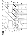
- FIG. 2 a schematic longitudinal section through the sealing element of a second embodiment of a seal arrangement in which the sealing lips of the dynamic sealing sections have different internal diameters;
- FIG. 3 a schematic longitudinal section through the sealing element of a third embodiment of a seal arrangement in which the sealing lips of the dynamic sealing sections have different internal diameters and wherein static sealing sections respectively associated with the dynamic sealing sections project in the axial direction beyond the dynamic sealing sections;
- FIG. 4 a schematic longitudinal section through the sealing element of a fourth embodiment of a seal arrangement in which the dynamic sealing sections have flattened sealing lips;
- FIG. 5 a schematic longitudinal section through a fifth embodiment of a seal arrangement in which the sealing element is provided with an additional stripping lip at the second sealing region;
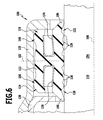
- FIG. 6 a schematic cross section through the sealing element of a sixth embodiment of a seal arrangement in which both sealing regions are provided with additional stripping lips;
- FIG. 7 a schematic longitudinal section through a seventh embodiment of a seal arrangement in which the second sealing region of the sealing element is provided with a stripping lip having a memory effect;
- FIG. 8 a schematic longitudinal section through the sealing element of an eighth embodiment of a seal arrangement in which the first dynamic sealing section has three sealing lips and the second dynamic sealing section has two sealing lips and a stripping lip with a memory effect.
- a seal arrangement for a high-pressure pump which bears the general reference 100 and is illustrated in FIG. 1 serves for sealing between a first medium space 128 which is filled with a liquid, fuel and in particular petrol for example, and a second medium space 130 which is filled with another liquid, with engine oil for example.
- the seal arrangement 100 comprises a seal carrier 132 having a central substantially hollow cylindrical seal seating region 134 and an outer ring-shaped edge region 136 surrounding the seal seating region 134 .
- a sleeve 138 is pressed into the seal carrier 132 , the central end wall 140 of said sleeve together with the seal seating region 134 of the seal carrier 132 bounding a seal space 142 in which a ring-shaped sealing element 112 is arranged.
- a first region 144 of the seal space 142 is connected via a through opening 146 in the end wall 140 of the sleeve 138 to the first medium space 128 so that this first region of the seal space 144 is filled with the first medium, the fuel for example.
- a second region 148 of the seal space 142 is connected via a through opening 150 in a central end wall 152 of the seal seating region 134 of the seal carrier 132 to the second medium space 130 and is thus filled with the second medium, with engine oil for example.
- the first region 144 and the second region 148 of the seal space 142 are separated from each other in substantially fluid-tight manner by a ring-shaped sealing element 112 arranged in the seal space 142 .
- a substantially cylindrical piston 110 which is displaceable along the longitudinal axis 108 thereof and the peripheral surface of which forms a piston bearing surface 154 , extends through the through opening 146 in the end wall 140 of the sleeve 138 , through the central ring opening of the sealing element 112 in the seal space 142 and through the through opening 150 in the end wall 152 of the seal carrier 132 from the first medium space 128 into the second medium space 130 .
- the sealing element 112 comprises a first sealing region 114 which is sealing with respect to the first medium space 128 , and a second sealing region 116 which is sealing with respect to the second medium space 130 .
- the first sealing region 114 comprises a first dynamic sealing section 118 which comprises three ring-shaped closed sealing lips 120 that are formed such as to be coaxial with the longitudinal axis 108 of the piston 110 which itself coincides with the longitudinal axis of the sealing element 112 , said sealing lips succeeding one another in the direction of the longitudinal axis 108 and each having a respective sharp sealing edge 156 which abuts against the piston bearing surface 154 .
- the first static sealing section 158 is separated from the first dynamic sealing section 118 by an annular groove 164 which is provided in the sealing element 112 and is open towards one axial end of the sealing element 112 and in which there is arranged a first ring-shaped closed spring element 126 the mutually opposite legs 166 a and 166 b of which respectively bias the first dynamic sealing section 118 against the piston bearing surface 154 and the first static sealing section 158 against the section 162 of the seal carrier 132 in resilient manner.
- the second sealing region 116 of the sealing element 112 comprises a second dynamic sealing section 122 which in like manner to the first dynamic sealing section 118 has three mutually spaced ring-shaped closed sealing lips 120 that are formed such as to be coaxial with the longitudinal axis 108 and succeed one another along the longitudinal axis 108 . These sealing lips 120 abut on the piston bearing surface 154 by means of a respective sharp sealing edge 156 .
- the second sealing region 116 of the sealing element 112 comprises a second static sealing section 168 which is arranged radially outwardly of the second dynamic sealing section 122 and includes a sealing lip 160 which abuts on the inner surface of the section 162 of the seal carrier 132 in sealing manner.
- the second static sealing section 168 projects in the axial direction, i.e. in the direction of the longitudinal axis 108 , beyond the end of the second dynamic sealing section 122 , whereby the projecting region forms a shoulder 170 with the aid of which the sealing element 112 is supported on the end wall 152 of the seal carrier 132 under the influence of an increased pressure in the first medium space 128 .
- the difference in pressure between the first medium space 128 and the second medium space 130 amounts to approximately 12 bar for example.
- the second static sealing section 168 is separated from the second dynamic sealing section 122 by an annular groove 172 which is formed in the sealing element 112 and is open towards one axial end of the sealing element 112 and in which there is arranged a second ring-shaped spring element 174 the legs 166 a and 166 b of which respectively bias the second dynamic sealing section 122 against the piston bearing surface 154 and the second static sealing section 168 against the section 162 of the seal carrier 132 in resilient manner.
- a central web 176 which protrudes radially inwardly towards the piston 110 and has a substantially cylindrical supporting surface 178 which abuts on the piston bearing surface 154 over a large surface space so that the sealing element 112 is guided thereby on the piston 110 .
- a respective ring-shaped leakage storage space 180 which is coaxial with the longitudinal axis 108 , whereby the successive leakage storage spaces 180 are separated from each other by the intermediary sealing edges 156 or by the central web 176 .
- Leakage liquid from the first medium space 128 is stored in the leakage storage spaces 180 of the first dynamic sealing section 118 and dragged back into the first medium space 128 during the return stroke of the piston 110 .
- leakage liquid from the second medium space 130 is collected in the leakage storage spaces 180 of the second dynamic sealing section 122 and dragged back again into the second medium space 130 during the return stroke of the piston.
- All six leakage storage spaces 180 of the sealing element 112 are of substantially the same size.
- the sealing element 112 is preferably in one-piece form and is made of a fluoropolymer material, for example, from PTFE or from a PTFE compound.
- the sealing element 112 can be formed, in particular, from a PTFE compound which contains up to 20 percent by weight of carbon fibres and the abut of PTFE.
- the sealing element 112 can be made from a hollow cylindrical blank of the sintered PTFE compound by a machining process.
- the spring elements 126 and 174 are preferably in the form of metallic annular springs having a U-, V- or C-shaped cross section.
- the sealing element 112 is substantially mirror-symmetrical with respect to a transverse central plane 182 running perpendicularly to the longitudinal axis 108 thereof. In this way, the effect is achieved that the orientation of the sealing element 112 relative to the piston 110 does not play a role and the sealing element 112 can thus also be inserted into the seal carrier 132 in a position rotated through 180°.
- the shoulders 170 of the static sealing sections 158 and 168 extend over a part of the respective neighbouring annular groove 164 and a respective leg 166 b of the spring element 126 and 174 arranged therein so that the spring elements 126 , 174 are retained in the respective annular groove 164 by the shoulders 170 .
- a second embodiment of a seal arrangement 100 that is illustrated in FIG. 2 differs from the first embodiment illustrated in FIG. 1 in that the leakage storage spaces 180 of each dynamic sealing section 118 , 122 are of different sizes in the second embodiment, whereby the size of the leakage storage spaces 180 decreases with increasing distance from the medium-space axial ends of the sealing element 112 so that the leakage storage spaces 180 a that are closest to the axial ends of the sealing element 112 have a greater volume than the neighbouring leakage storage spaces 180 b located closer to the transverse central plane 182 of the sealing element 112 and these in turn have a greater volume than the leakage storage spaces 180 c that are located closest to the transverse central plane 182 .
- the different sizes of the leakage storage spaces 180 are obtained in that the sealing lips bounding the leakage storage spaces 180 and the central web 176 have different internal diameters in the manufacturing state of the sealing element 112 .
- the internal diameter D of the sealing lips 120 increases with increasing distance from the axial ends of the sealing element 112 so that the internal diameter D 1 at the sealing edge 156 of the outermost sealing lips 120 a located closest to the axial ends of the sealing element 112 is smaller than the internal diameter D 2 at the sealing edge 156 of the middle sealing lips 120 b located more closely to the transverse central plane 182 of the sealing element 112 , and their internal diameter D 2 is again smaller than the internal diameter D 3 at the sealing edge 156 of the inner sealing lips 120 c that are located closest to the transverse central plane 182 of the sealing element 112 .
- the internal diameter D 3 of the inner sealing lip 120 c is in turn smaller than the internal diameter D 4 of the supporting surface 178 of the central web 176 .
- the dynamic sealing sections 118 , 122 are deformed in such a way that the sealing lips 120 are all of the same internal diameter at their sealing edges 156 , this diameter corresponding to the external diameter of the piston 110 so that the sealing edges 156 all abut against the piston bearing surface 154 when the seal arrangement is in operation.
- the outwardly oriented boundary surfaces 184 i.e. those oriented towards the nearest axial end of the sealing element 112 have a differing angle of inclination (a) with respect to a plane 186 running perpendicularly to the longitudinal axis 108 than the inwardly oriented boundary surfaces 188 of the sealing lips 120 , i.e. those oriented towards the transverse central plane 182 of the sealing element 112 .
- the outwardly oriented boundary surfaces 184 are steeper than the inwardly oriented boundary surfaces 188 , i.e. the outwardly oriented boundary surfaces 184 are inclined at an angle a with respect to the plane 186 running perpendicularly to the longitudinal axis 108 , this angle being smaller than the angle ⁇ at which the inwardly oriented boundary surfaces 188 of the sealing lips 120 are inclined to this plane 186 .
- the effect is achieved that the leakage liquid can only overcome the sealing lips 120 with difficulty in a direction away from an axial end of the sealing element 112 towards the transverse central plane 182 of the sealing element 112 , but can easily be dragged back in the opposite direction away from the transverse central plane 182 towards an axial end of the sealing element 112 .
- the static sealing sections 158 and 168 of the sealing element 112 of the second embodiment do not project beyond the respectively associated first dynamic sealing section 118 and second dynamic sealing section 122 , but rather, they end at the same distance from the transverse central plane 182 as the respectively associated dynamic sealing section 118 and 122 .
- a third embodiment of a seal arrangement 100 that is illustrated in FIG. 3 differs from the second embodiment illustrated in FIG. 2 in that the axial ends 190 of the dynamic sealing sections 118 and 122 are set back in relation to the axial ends 192 of the respectively associated static sealing sections 158 , 168 by a distance L with respect to the transverse central plane 182 of the sealing element 112 .
- a fourth embodiment of a seal arrangement 100 that is illustrated in FIG. 4 differs from the second embodiment illustrated in FIG. 2 in that the sealing lips 120 of the dynamic sealing sections 118 and 122 do not have sharp sealing edges 156 , but instead, are flattened and abut flatly against the piston bearing surface 154 by means of substantially cylindrical supporting surfaces 194 which respectively extend in parallel with the longitudinal axis 108 over a distance A.
- a fifth embodiment of a seal arrangement 100 that is illustrated in FIG. 5 differs from the third embodiment illustrated in FIG. 3 in that, in addition to the three sealing lips 120 , the second dynamic sealing section 122 of the sealing element 112 is provided with a stripping lip 196 which projects in the axial direction beyond the second static sealing section 168 and abuts against the piston bearing surface 154 .
- sealing lip 120 a of the second dynamic sealing section 122 that is located closest to the axial end of the sealing element 112 could also be made instead.
- a sixth embodiment of a seal arrangement 100 that is illustrated in FIG. 6 differs from the fifth embodiment illustrated in FIG. 5 in that the sealing element 112 is such that it is mirror-symmetrical with respect to the transverse central plane 182 thereof and thus, in addition to the respective three sealing lips 120 , it also has a respective stripping lip 196 on each of its dynamic sealing sections 118 , 122 and this stripping lip projects in the axial direction beyond the respectively associated static sealing section 158 and 168 .
- sealing element 112 Due to the symmetry of the sealing element 112 with respect to the transverse central plane 182 thereof, it is ensured that the sealing element 112 can also be inserted into the seal carrier 132 at a position rotated through 180°, this thereby simplifying the assembly of the seal arrangement 100 .
- a seventh embodiment of a seal arrangement 100 that is illustrated in FIG. 7 differs from the fifth embodiment illustrated in FIG. 5 in that the additional stripping lip 196 of the second dynamic sealing section 122 is in the form of a memory stripping lip 198 , i.e. it is in the form of a stripping lip which is biased against the piston bearing surface 154 by a memory effect of the fluoropolymer material being used, in particular, a PTFE or a PTFE compound material.
- This memory effect comes into being due to the fact that when the memory stripping lip 198 is first being produced it is subjected to a machining process so as have an internal diameter which is smaller than the external diameter of the piston 110 , and the memory stripping lip 198 is subsequently deformed at ambient temperature or at a higher temperature in such a manner that the piston 110 can be passed therethrough.
- the seal arrangement 100 heats up during operation of the high-pressure pump, the PTFE-containing material of the memory stripping lip 198 deforms back to its original shape.
- the memory stripping lip 198 is biased against the piston bearing surface 154 and is continually readjusted against the piston 110 in the course of wearing of the memory stripping lip 198 which occurs when the seal arrangement 100 is in operation, this thereby ensuring that the memory stripping lip 198 always produces an adequate stripping effect.
- An eighth embodiment of a seal arrangement 100 that is illustrated in FIG. 8 differs from the seventh embodiment illustrated in FIG. 7 in that the sealing lip 120 a of the second dynamic sealing section 122 nearest the axial end has been dispensed with and thus the second dynamic sealing section 122 has been shortened in such a way that its axial end 190 has been set back in relation to the axial end 192 of the second static sealing section 168 by the distance L, and as a result, the second dynamic sealing section is not loaded when the sealing element 112 is pressing into the seal carrier 132 .
Landscapes
- Engineering & Computer Science (AREA)
- General Engineering & Computer Science (AREA)
- Mechanical Engineering (AREA)
- Chemical & Material Sciences (AREA)
- Combustion & Propulsion (AREA)
- Sealing Devices (AREA)
- Sealing With Elastic Sealing Lips (AREA)
- Fuel-Injection Apparatus (AREA)
Abstract
Description
Claims (25)
Applications Claiming Priority (3)
| Application Number | Priority Date | Filing Date | Title |
|---|---|---|---|
| DE102006055298A DE102006055298A1 (en) | 2006-11-23 | 2006-11-23 | sealing arrangement |
| DE102006055298 | 2006-11-23 | ||
| DE102006055298.9 | 2006-11-23 |
Publications (2)
| Publication Number | Publication Date |
|---|---|
| US20080122184A1 US20080122184A1 (en) | 2008-05-29 |
| US7959159B2 true US7959159B2 (en) | 2011-06-14 |
Family
ID=38969896
Family Applications (1)
| Application Number | Title | Priority Date | Filing Date |
|---|---|---|---|
| US11/903,341 Active 2029-06-16 US7959159B2 (en) | 2006-11-23 | 2007-09-21 | Sealing arrangement |
Country Status (6)
| Country | Link |
|---|---|
| US (1) | US7959159B2 (en) |
| EP (1) | EP2047148B1 (en) |
| JP (1) | JP5196383B2 (en) |
| CN (1) | CN101529140B (en) |
| DE (1) | DE102006055298A1 (en) |
| WO (1) | WO2008061581A1 (en) |
Cited By (29)
| Publication number | Priority date | Publication date | Assignee | Title |
|---|---|---|---|---|
| US20100052267A1 (en) * | 2008-08-28 | 2010-03-04 | Castleman Larry J | Seal assembly |
| US20100119297A1 (en) * | 2008-11-07 | 2010-05-13 | Trw Automotive U.S. Llc | Sealing structure for use with a ball and socket joint |
| US20100133757A1 (en) * | 2007-04-09 | 2010-06-03 | Nok Corporation | Sealing device |
| US20100206575A1 (en) * | 2007-11-05 | 2010-08-19 | Cameron International Corporation | Self-Energizing Annular Seal |
| US20110006486A1 (en) * | 2009-07-08 | 2011-01-13 | Sidney Niknezhad | Double direction seal with locking |
| US20110108007A1 (en) * | 2009-11-03 | 2011-05-12 | MAGNETI MARELLI S.p.A. | Fuel pump with reduced seal wear for a direct injection system |
| US20110140369A1 (en) * | 2009-12-11 | 2011-06-16 | Saint-Gobain Performance Plastics Corporation | System, method and apparatus for spring-energized dynamic sealing assembly |
| US20120146293A1 (en) * | 2009-08-19 | 2012-06-14 | Robert Bosch Gmbh | Spring-elastic axial seal |
| US20130043660A1 (en) * | 2011-08-15 | 2013-02-21 | Elringklinger Ag | Seal for sealing a sealing gap and method for producing a seal of this type |
| US20140150748A1 (en) * | 2012-11-30 | 2014-06-05 | GM Global Technology Operations LLC | Seal alignment systems |
| US20140217318A1 (en) * | 2011-09-01 | 2014-08-07 | Rausch & Pausch Gmbh | Seal and control device having said seal |
| US20150102247A1 (en) * | 2013-09-30 | 2015-04-16 | Saint-Gobain Performance Plastics Corporation | Valve and choke stem packing assemblies |
| US20150115547A1 (en) * | 2013-10-24 | 2015-04-30 | Aktiebolaget Skf | Seal with Tabs for Retaining Energizing Member |
| US20150285390A1 (en) * | 2012-12-19 | 2015-10-08 | Elringklinger Ag | Sealing ring for a pressure control valve |
| US20150337614A1 (en) * | 2014-05-23 | 2015-11-26 | Baker Hughes Incorporated | Downhole seal protector arrangement |
| US20160018002A1 (en) * | 2014-07-09 | 2016-01-21 | Saint-Gobain Performance Plastics Corporation | Polymer seal assembly |
| US20160319936A1 (en) * | 2015-05-01 | 2016-11-03 | Saint-Gobain Performance Plastics Corporation | Seals |
| US20170261105A1 (en) * | 2014-11-28 | 2017-09-14 | Elringklinger Ag | Sealing element and method for producing a sealing element |
| US20170343110A1 (en) * | 2013-02-20 | 2017-11-30 | Nok Corporation | Sealing device |
| US10386017B2 (en) * | 2015-12-03 | 2019-08-20 | Engineered Controls International, Llc | Low emission nozzles and receptacles |
| US10393112B2 (en) * | 2014-02-17 | 2019-08-27 | Robert Bosch Gmbh | Piston fuel pump for an internal combustion engine |
| US20190264747A1 (en) * | 2018-02-28 | 2019-08-29 | Aktiebolaget Skf | Bearing |
| KR20190116440A (en) * | 2017-02-17 | 2019-10-14 | 트렐레보르크 씰링 솔루션즈 저머니 게엠베하 | Sealing device with improved lubrication |
| US10495227B2 (en) * | 2014-02-14 | 2019-12-03 | Aktiebolaget Skf | Dynamic seal |
| US20200056608A1 (en) * | 2018-08-15 | 2020-02-20 | Xiaorong Li | Sealing structure of plunger pump |
| US11162589B2 (en) * | 2018-10-26 | 2021-11-02 | Parker-Hannifin Corporation | Exclusion and pulsation seal for hydraulic fracturing pump |
| US11840995B2 (en) * | 2016-06-06 | 2023-12-12 | Elringklinger Ag | Piston device and pump device |
| US20250060037A1 (en) * | 2022-05-11 | 2025-02-20 | Trelleborg Sealing Solutions Germany Gmbh | Shaft sealing ring and shaft arrangement for high rotational speeds |
| US20250180121A1 (en) * | 2022-11-01 | 2025-06-05 | Bal Seal Engineering, Llc | Lip seals and related methods |
Families Citing this family (47)
| Publication number | Priority date | Publication date | Assignee | Title |
|---|---|---|---|---|
| US8419020B2 (en) * | 2004-11-22 | 2013-04-16 | Mide Technology Corporation | Fluid activated shaft seal |
| US7640917B2 (en) * | 2007-06-21 | 2010-01-05 | Freudenberg-Nok General Partnership | Gas direct injector tip seal |
| US7968167B2 (en) * | 2009-10-22 | 2011-06-28 | GM Global Technology Operations LLC | Coated seal for sealing parts in a vehicle engine |
| DE102009047590B4 (en) * | 2009-12-07 | 2022-05-19 | Robert Bosch Gmbh | Piston pump with a sealing arrangement |
| US8454025B2 (en) * | 2010-02-24 | 2013-06-04 | Freudenberg-Nok General Partnership | Seal with spiral grooves and mid-lip band |
| US8328201B2 (en) * | 2010-06-23 | 2012-12-11 | Aktiebolaget Skf | Pumping seal assembly with angled spring |
| DE102010052558B4 (en) * | 2010-11-25 | 2025-05-28 | Van Halteren Technologies Boxtel B.V. | V-ring for a V-ring seal kit |
| DE102012203931A1 (en) * | 2011-08-02 | 2013-02-07 | Continental Teves Ag & Co. Ohg | piston pump |
| DE102011082007B3 (en) * | 2011-09-01 | 2013-01-10 | Rausch & Pausch Gmbh | Seal and control device with this seal |
| DE102012212889A1 (en) * | 2012-07-23 | 2014-01-23 | Robert Bosch Gmbh | Sealing ring for pump element of hydraulic unit of vehicle brake system, has small-volume fluid reservoir for temporarily storing brake fluid that is formed in sealing surface |
| CN102817720A (en) * | 2012-08-30 | 2012-12-12 | 济南鲁新金属制品有限公司 | Fuel-cut cylinder of engine |
| DE102012018652B4 (en) * | 2012-09-20 | 2016-03-10 | Eagleburgmann Germany Gmbh & Co. Kg | Cartridge assembly with sealing ring and agitator with such a cartridge assembly |
| WO2014095120A1 (en) | 2012-12-20 | 2014-06-26 | Robert Bosch Gmbh | Piston fuel pump for an internal combustion engine |
| DE102013000514B4 (en) * | 2013-01-15 | 2015-09-24 | Carl Freudenberg Kg | Sealing arrangement and its use |
| EP2821646A1 (en) * | 2013-07-01 | 2015-01-07 | Delphi International Operations Luxembourg S.à r.l. | High pressure pump |
| WO2015032558A1 (en) * | 2013-09-04 | 2015-03-12 | Continental Automotive Gmbh | High pressure pump |
| DE102014214296A1 (en) | 2014-07-22 | 2016-01-28 | Robert Bosch Gmbh | High-pressure fuel pump, in particular plug-in pump |
| DE102014214294A1 (en) * | 2014-07-22 | 2016-01-28 | Robert Bosch Gmbh | High-pressure fuel pump, in particular plug-in pump |
| DE102014214293A1 (en) | 2014-07-22 | 2016-01-28 | Robert Bosch Gmbh | High-pressure fuel pump, in particular plug-in pump |
| DE102014214282A1 (en) | 2014-07-22 | 2016-01-28 | Robert Bosch Gmbh | High-pressure fuel pump, in particular plug-in pump |
| DE102014218992A1 (en) | 2014-09-22 | 2016-03-24 | Robert Bosch Gmbh | High-pressure fuel pump |
| DE102014220705B4 (en) | 2014-10-13 | 2016-05-04 | Continental Automotive Gmbh | High-pressure pump for a fuel injection system of an internal combustion engine |
| DE102014223162A1 (en) * | 2014-11-13 | 2016-05-19 | Elringklinger Ag | sealing arrangement |
| US9897210B2 (en) * | 2014-12-08 | 2018-02-20 | United Technologies Corporation | Knife edge seal tree |
| DE102014225319A1 (en) * | 2014-12-09 | 2016-06-09 | Robert Bosch Gmbh | High-pressure fuel pump with a piston |
| DE102014225925A1 (en) * | 2014-12-15 | 2016-06-16 | Elringklinger Ag | Sealing arrangement and method for mounting a seal assembly |
| US10180188B2 (en) * | 2016-02-10 | 2019-01-15 | Onesubsea Ip Uk Limited | Multi-material seal with lip portions |
| CN107345516B (en) * | 2016-05-05 | 2020-08-07 | 博世汽车柴油系统有限公司 | Plunger sealing ring for high-pressure fuel pump and corresponding high-pressure fuel pump |
| CN105952620A (en) * | 2016-05-13 | 2016-09-21 | 蚌埠市金鹏燃气设备制造有限公司 | Oil scraping device for piston type compressor |
| JP6953264B2 (en) * | 2016-11-07 | 2021-10-27 | 株式会社ジェイテクト | Sealed structure |
| DE102017211353A1 (en) * | 2017-07-04 | 2019-01-10 | Robert Bosch Gmbh | High-pressure fuel pump |
| JP6851481B2 (en) * | 2017-07-14 | 2021-03-31 | 日立Astemo株式会社 | High pressure fuel pump |
| CN108422988B (en) * | 2018-03-08 | 2019-09-17 | 浙江工贸职业技术学院 | Double-cylinder type auxiliary brake cylinder mechanism |
| DE102018206312A1 (en) | 2018-04-24 | 2018-07-19 | Robert Bosch Gmbh | Sealing device for a high-pressure fuel pump with a piston |
| DE112019004550T5 (en) * | 2018-10-19 | 2021-06-17 | Hitachi Astemo, Ltd. | HIGH PRESSURE FUEL PUMP |
| CN111207017A (en) * | 2018-11-22 | 2020-05-29 | 美国圣戈班性能塑料公司 | Ring seals, seal assemblies and high pressure fuel pumps |
| JP7325032B2 (en) * | 2018-12-28 | 2023-08-14 | 株式会社ソミックマネージメントホールディングス | Seal body and rotary damper |
| CN110056535B (en) * | 2019-05-27 | 2020-09-11 | 新乡市中机工业有限公司 | A wear-resistant and corrosion-resistant mouth ring device for a water pump |
| DE102019212262A1 (en) | 2019-08-15 | 2021-02-18 | Elringklinger Ag | Sealing arrangement, high pressure pump and method for producing a sealing arrangement |
| CN110762221A (en) * | 2019-11-20 | 2020-02-07 | 泰铂(上海)环保科技股份有限公司 | Axial self-sealing shaft seal device and compressor |
| KR102263660B1 (en) * | 2019-12-17 | 2021-06-10 | 주식회사 현대케피코 | Guide for piston of High pressure pump |
| CN118140080A (en) * | 2021-10-27 | 2024-06-04 | 美国圣戈班性能塑料公司 | Seal with insert and method of making and using the same |
| CN114265013B (en) * | 2021-11-16 | 2025-10-24 | 中国航空工业集团公司雷华电子技术研究所 | A water hinge joint |
| US11940049B1 (en) * | 2022-11-01 | 2024-03-26 | Bal Seal Engineering, Llc | Lip seals and related methods |
| US20250012327A1 (en) * | 2023-07-03 | 2025-01-09 | Hanon Systems | Combination seal and bearing |
| DE102024113262A1 (en) * | 2024-05-13 | 2025-11-13 | Eagleburgmann Germany Gmbh & Co. Kg | mechanical seal arrangement |
| CN119664745B (en) * | 2024-12-13 | 2025-06-17 | 冈田智能(江苏)股份有限公司 | Universal sealing structure for middle-spraying direct-connection main shaft pull rod power assembly |
Citations (34)
| Publication number | Priority date | Publication date | Assignee | Title |
|---|---|---|---|---|
| US2088703A (en) * | 1935-11-02 | 1937-08-03 | Garlock Packing Co | Machinery packing |
| US2167603A (en) * | 1936-11-06 | 1939-07-25 | Victor Mfg & Gasket Co | Grease retainer with unitary diaphragms and supports |
| US2185790A (en) * | 1937-08-07 | 1940-01-02 | Victor Mfg & Gasket Co | Double wipe fluid seal |
| US2446380A (en) * | 1945-04-12 | 1948-08-03 | Ohio Rubber Co | Fluid seal |
| US2841429A (en) * | 1955-10-04 | 1958-07-01 | Parker Hannifin Corp | Sealing ring and joint |
| GB810625A (en) | 1955-10-04 | 1959-03-18 | Parker Hannifin Corp | Sealing or packing ring and joint including such ring |
| US3215441A (en) * | 1962-05-17 | 1965-11-02 | Prec Associates Inc | Resilient seal and distortion controlling means therefor |
| US3218087A (en) | 1962-07-09 | 1965-11-16 | Boeing Co | Foot seal |
| US3550990A (en) * | 1969-06-17 | 1970-12-29 | Minnesota Rubber Co | Sealing device |
| US3612551A (en) * | 1969-11-06 | 1971-10-12 | Trw Inc | Bidirectional lip seal |
| US3854737A (en) * | 1974-01-21 | 1974-12-17 | Chemprene | Combination rotary and reciprocating unitary sealing mechanism |
| US4232873A (en) * | 1979-03-12 | 1980-11-11 | Hock Jules M | Ring spring for composite machinery seals and method of manufacturing same |
| DE3403686A1 (en) | 1984-02-03 | 1985-08-08 | Elring Dichtungswerke Gmbh, 7012 Fellbach | Radial shaft sealing ring |
| US4592558A (en) * | 1984-10-17 | 1986-06-03 | Hydril Company | Spring ring and hat ring seal |
| GB2296538A (en) | 1994-12-28 | 1996-07-03 | Nok Corp | Shaft seal with dust sealing lip |
| US5626520A (en) * | 1995-06-14 | 1997-05-06 | The Zeller Corporation | Reversible universal joint seal |
| US5671656A (en) | 1996-02-20 | 1997-09-30 | Wagner Spray Tech Corporation | Paint pump fluid section |
| JPH09303569A (en) | 1996-05-17 | 1997-11-25 | Eagle Ind Co Ltd | Lip type seal |
| US5897119A (en) * | 1997-04-18 | 1999-04-27 | Garlock, Inc. | Floating wiper seal assembly |
| US6079715A (en) * | 1996-10-15 | 2000-06-27 | Dichtungstechnik G. Bruss Gmbh & Co. Kg | Rotary shaft seal having a PTFE seal lip and a method and apparatus of manufacturing same |
| US6168164B1 (en) * | 1998-12-08 | 2001-01-02 | Federal-Mogul World Wide, Inc. | Hydrodynamic seal and method of manufacture |
| EP1273835A2 (en) | 2001-07-06 | 2003-01-08 | Hitachi, Ltd. | Seal mechanism and fuel pump provided therewith |
| US6705617B2 (en) * | 2001-11-28 | 2004-03-16 | Federal-Mogul World Wide, Inc. | Hydrodynamic seal and method of making the same |
| US6726211B1 (en) * | 1998-06-12 | 2004-04-27 | Nok Corporation | Sealing device |
| US6860486B2 (en) * | 2001-11-08 | 2005-03-01 | Dichtungstechnik G. Bruss Gmbh & Co. Kg | Shaft sealing ring |
| DE10338587A1 (en) | 2003-08-22 | 2005-03-24 | Elringklinger Ag | Shaft seal comprises an annular sealing element for sealing a media side and an outer side of the shaft seal with a recirculating structure having an closed annular channel and a connecting channel |
| WO2005100794A1 (en) | 2004-04-13 | 2005-10-27 | Nok Corporation | Plunger seal for pump |
| DE102004040105A1 (en) | 2004-08-18 | 2006-03-09 | Carl Freudenberg Kg | Seal with Rückfördernuten whose slope increases in the direction of the environment |
| US20060103075A1 (en) | 2004-11-15 | 2006-05-18 | Zahn Henry W | Triple lip fork seal |
| WO2006134756A1 (en) | 2005-06-14 | 2006-12-21 | Nok Corporation | Lip type seal |
| WO2007082111A1 (en) | 2006-01-05 | 2007-07-19 | Saint-Gobain Performance Plastics Corporation | Annular seal and pump including same |
| US20070182103A1 (en) | 2001-06-04 | 2007-08-09 | Nok Corporation | Sealing device |
| US20080073856A1 (en) * | 2006-09-21 | 2008-03-27 | Nok Corporation | Sealing device for reciprocating shaft |
| US7686308B2 (en) * | 2004-11-22 | 2010-03-30 | Mide Technology Corporation | Fluid-activated shaft seal |
Family Cites Families (7)
| Publication number | Priority date | Publication date | Assignee | Title |
|---|---|---|---|---|
| DE3309538C2 (en) * | 1983-03-17 | 1986-05-28 | Fa. Carl Freudenberg, 6940 Weinheim | poetry |
| US4560177A (en) * | 1984-08-09 | 1985-12-24 | Chicago Rawhide Mfg. Co. | Contoured shaft seal for high pressure applications |
| JPH0139967Y2 (en) * | 1985-11-29 | 1989-11-30 | ||
| CN2149522Y (en) * | 1993-02-13 | 1993-12-15 | 于静 | Automatic sealing ring |
| CN2180838Y (en) * | 1993-11-01 | 1994-10-26 | 重庆市九龙坡区西站橡胶制品厂 | Framework type rubber oil sealing device |
| JPH1171574A (en) * | 1997-06-16 | 1999-03-16 | Daikin Ind Ltd | Seal material |
| JP2005147317A (en) * | 2003-11-18 | 2005-06-09 | Nok Corp | Sealing device and fuel injection pump |
-
2006
- 2006-11-23 DE DE102006055298A patent/DE102006055298A1/en not_active Withdrawn
-
2007
- 2007-09-12 JP JP2009537491A patent/JP5196383B2/en active Active
- 2007-09-12 CN CN200780037333XA patent/CN101529140B/en active Active
- 2007-09-12 EP EP07802274A patent/EP2047148B1/en active Active
- 2007-09-12 WO PCT/EP2007/007934 patent/WO2008061581A1/en not_active Ceased
- 2007-09-21 US US11/903,341 patent/US7959159B2/en active Active
Patent Citations (35)
| Publication number | Priority date | Publication date | Assignee | Title |
|---|---|---|---|---|
| US2088703A (en) * | 1935-11-02 | 1937-08-03 | Garlock Packing Co | Machinery packing |
| US2167603A (en) * | 1936-11-06 | 1939-07-25 | Victor Mfg & Gasket Co | Grease retainer with unitary diaphragms and supports |
| US2185790A (en) * | 1937-08-07 | 1940-01-02 | Victor Mfg & Gasket Co | Double wipe fluid seal |
| US2446380A (en) * | 1945-04-12 | 1948-08-03 | Ohio Rubber Co | Fluid seal |
| US2841429A (en) * | 1955-10-04 | 1958-07-01 | Parker Hannifin Corp | Sealing ring and joint |
| GB810625A (en) | 1955-10-04 | 1959-03-18 | Parker Hannifin Corp | Sealing or packing ring and joint including such ring |
| US3215441A (en) * | 1962-05-17 | 1965-11-02 | Prec Associates Inc | Resilient seal and distortion controlling means therefor |
| US3218087A (en) | 1962-07-09 | 1965-11-16 | Boeing Co | Foot seal |
| US3550990A (en) * | 1969-06-17 | 1970-12-29 | Minnesota Rubber Co | Sealing device |
| US3612551A (en) * | 1969-11-06 | 1971-10-12 | Trw Inc | Bidirectional lip seal |
| US3854737A (en) * | 1974-01-21 | 1974-12-17 | Chemprene | Combination rotary and reciprocating unitary sealing mechanism |
| US4232873A (en) * | 1979-03-12 | 1980-11-11 | Hock Jules M | Ring spring for composite machinery seals and method of manufacturing same |
| DE3403686A1 (en) | 1984-02-03 | 1985-08-08 | Elring Dichtungswerke Gmbh, 7012 Fellbach | Radial shaft sealing ring |
| US4592558A (en) * | 1984-10-17 | 1986-06-03 | Hydril Company | Spring ring and hat ring seal |
| GB2296538A (en) | 1994-12-28 | 1996-07-03 | Nok Corp | Shaft seal with dust sealing lip |
| US5626520A (en) * | 1995-06-14 | 1997-05-06 | The Zeller Corporation | Reversible universal joint seal |
| US5671656A (en) | 1996-02-20 | 1997-09-30 | Wagner Spray Tech Corporation | Paint pump fluid section |
| JPH09303569A (en) | 1996-05-17 | 1997-11-25 | Eagle Ind Co Ltd | Lip type seal |
| US6079715A (en) * | 1996-10-15 | 2000-06-27 | Dichtungstechnik G. Bruss Gmbh & Co. Kg | Rotary shaft seal having a PTFE seal lip and a method and apparatus of manufacturing same |
| US5897119A (en) * | 1997-04-18 | 1999-04-27 | Garlock, Inc. | Floating wiper seal assembly |
| US6726211B1 (en) * | 1998-06-12 | 2004-04-27 | Nok Corporation | Sealing device |
| US6168164B1 (en) * | 1998-12-08 | 2001-01-02 | Federal-Mogul World Wide, Inc. | Hydrodynamic seal and method of manufacture |
| US20070182103A1 (en) | 2001-06-04 | 2007-08-09 | Nok Corporation | Sealing device |
| EP1273835A2 (en) | 2001-07-06 | 2003-01-08 | Hitachi, Ltd. | Seal mechanism and fuel pump provided therewith |
| US6860486B2 (en) * | 2001-11-08 | 2005-03-01 | Dichtungstechnik G. Bruss Gmbh & Co. Kg | Shaft sealing ring |
| US6705617B2 (en) * | 2001-11-28 | 2004-03-16 | Federal-Mogul World Wide, Inc. | Hydrodynamic seal and method of making the same |
| DE10338587A1 (en) | 2003-08-22 | 2005-03-24 | Elringklinger Ag | Shaft seal comprises an annular sealing element for sealing a media side and an outer side of the shaft seal with a recirculating structure having an closed annular channel and a connecting channel |
| WO2005100794A1 (en) | 2004-04-13 | 2005-10-27 | Nok Corporation | Plunger seal for pump |
| DE102004040105A1 (en) | 2004-08-18 | 2006-03-09 | Carl Freudenberg Kg | Seal with Rückfördernuten whose slope increases in the direction of the environment |
| US20060103075A1 (en) | 2004-11-15 | 2006-05-18 | Zahn Henry W | Triple lip fork seal |
| US7686308B2 (en) * | 2004-11-22 | 2010-03-30 | Mide Technology Corporation | Fluid-activated shaft seal |
| WO2006134756A1 (en) | 2005-06-14 | 2006-12-21 | Nok Corporation | Lip type seal |
| US20090302549A1 (en) | 2005-06-14 | 2009-12-10 | Nok Corporation | Lip Type Seal |
| WO2007082111A1 (en) | 2006-01-05 | 2007-07-19 | Saint-Gobain Performance Plastics Corporation | Annular seal and pump including same |
| US20080073856A1 (en) * | 2006-09-21 | 2008-03-27 | Nok Corporation | Sealing device for reciprocating shaft |
Cited By (59)
| Publication number | Priority date | Publication date | Assignee | Title |
|---|---|---|---|---|
| US8585059B2 (en) | 2007-04-09 | 2013-11-19 | Nok Corporation | Sealing device |
| US8313104B2 (en) * | 2007-04-09 | 2012-11-20 | Nok Corporation | Sealing device |
| US20100133757A1 (en) * | 2007-04-09 | 2010-06-03 | Nok Corporation | Sealing device |
| US20100206575A1 (en) * | 2007-11-05 | 2010-08-19 | Cameron International Corporation | Self-Energizing Annular Seal |
| US9376882B2 (en) * | 2007-11-05 | 2016-06-28 | Onesubsea Ip Uk Limited | Self-energizing annular seal |
| US20100052267A1 (en) * | 2008-08-28 | 2010-03-04 | Castleman Larry J | Seal assembly |
| US9803752B2 (en) * | 2008-08-28 | 2017-10-31 | Trelleborg Sealing Solutions Us, Inc. | Seal assembly |
| US8215646B2 (en) * | 2008-08-28 | 2012-07-10 | Castleman Larry J | Seal assembly |
| US20120313327A1 (en) * | 2008-08-28 | 2012-12-13 | Castleman Larry J | Seal assembly |
| US20100119297A1 (en) * | 2008-11-07 | 2010-05-13 | Trw Automotive U.S. Llc | Sealing structure for use with a ball and socket joint |
| US8414215B2 (en) * | 2008-11-07 | 2013-04-09 | Trw Automotive U.S. Llc | Sealing structure for use with a ball and socket joint |
| US20110006486A1 (en) * | 2009-07-08 | 2011-01-13 | Sidney Niknezhad | Double direction seal with locking |
| US10520091B2 (en) * | 2009-07-08 | 2019-12-31 | Bal Seal Engineering, Inc. | Double direction seal with locking |
| US8668204B2 (en) * | 2009-08-19 | 2014-03-11 | Robert Bosch Gmbh | Spring-elastic axial seal |
| US20120146293A1 (en) * | 2009-08-19 | 2012-06-14 | Robert Bosch Gmbh | Spring-elastic axial seal |
| US8556602B2 (en) * | 2009-11-03 | 2013-10-15 | MAGNETI MARELLI S.p.A. | Fuel pump with reduced seal wear for a direct injection system |
| US20110108007A1 (en) * | 2009-11-03 | 2011-05-12 | MAGNETI MARELLI S.p.A. | Fuel pump with reduced seal wear for a direct injection system |
| US20110140369A1 (en) * | 2009-12-11 | 2011-06-16 | Saint-Gobain Performance Plastics Corporation | System, method and apparatus for spring-energized dynamic sealing assembly |
| US20140361494A1 (en) * | 2009-12-11 | 2014-12-11 | Saint-Gobain Performance Plastics Corporation | System, method and apparatus for spring-energized dynamic sealing assembly |
| US20140361492A1 (en) * | 2009-12-11 | 2014-12-11 | Saint-Gobain Performance Plastics Corporation | System, method and apparatus for spring-energized dynamic sealing assembly |
| US9182041B2 (en) * | 2011-08-15 | 2015-11-10 | Elringklinger Ag | Seal for sealing a sealing gap and method for producing a seal of this type |
| US20130043660A1 (en) * | 2011-08-15 | 2013-02-21 | Elringklinger Ag | Seal for sealing a sealing gap and method for producing a seal of this type |
| US9388913B2 (en) * | 2011-09-01 | 2016-07-12 | Rausch & Pausch Gmbh | Seal and control device having said seal |
| US20140217318A1 (en) * | 2011-09-01 | 2014-08-07 | Rausch & Pausch Gmbh | Seal and control device having said seal |
| US8863721B2 (en) * | 2012-11-30 | 2014-10-21 | GM Global Technology Operations LLC | Seal alignment systems |
| US20140150748A1 (en) * | 2012-11-30 | 2014-06-05 | GM Global Technology Operations LLC | Seal alignment systems |
| US20150285390A1 (en) * | 2012-12-19 | 2015-10-08 | Elringklinger Ag | Sealing ring for a pressure control valve |
| US20170343110A1 (en) * | 2013-02-20 | 2017-11-30 | Nok Corporation | Sealing device |
| US10359114B2 (en) * | 2013-02-20 | 2019-07-23 | Nok Corporation | Sealing device |
| US20150102247A1 (en) * | 2013-09-30 | 2015-04-16 | Saint-Gobain Performance Plastics Corporation | Valve and choke stem packing assemblies |
| US10415719B2 (en) * | 2013-09-30 | 2019-09-17 | Saint-Gobain Performance Plastics Corporation | Valve and choke stem packing assemblies |
| US20150115547A1 (en) * | 2013-10-24 | 2015-04-30 | Aktiebolaget Skf | Seal with Tabs for Retaining Energizing Member |
| US10495227B2 (en) * | 2014-02-14 | 2019-12-03 | Aktiebolaget Skf | Dynamic seal |
| US10697546B2 (en) * | 2014-02-14 | 2020-06-30 | Aktiebolaget Skf | Dynamic seal |
| US10393112B2 (en) * | 2014-02-17 | 2019-08-27 | Robert Bosch Gmbh | Piston fuel pump for an internal combustion engine |
| US20150337614A1 (en) * | 2014-05-23 | 2015-11-26 | Baker Hughes Incorporated | Downhole seal protector arrangement |
| US20160018002A1 (en) * | 2014-07-09 | 2016-01-21 | Saint-Gobain Performance Plastics Corporation | Polymer seal assembly |
| US11460112B2 (en) * | 2014-07-09 | 2022-10-04 | Saint-Gobain Performance Plastics Corporation | Polymer seal assembly |
| US10260634B2 (en) * | 2014-07-09 | 2019-04-16 | Saint-Gobain Performance Plastics Corporation | Polymer seal assembly |
| US10774932B2 (en) | 2014-11-28 | 2020-09-15 | Elringklinger Ag | Sealing element and method for producing a sealing element |
| US20210254720A1 (en) * | 2014-11-28 | 2021-08-19 | Elringklinger Ag | Sealing element and method for producing a sealing element |
| US20170261105A1 (en) * | 2014-11-28 | 2017-09-14 | Elringklinger Ag | Sealing element and method for producing a sealing element |
| US20210341059A1 (en) * | 2014-11-28 | 2021-11-04 | Elringklinger Ag | Sealing element and method for producing a sealing element |
| US20160319936A1 (en) * | 2015-05-01 | 2016-11-03 | Saint-Gobain Performance Plastics Corporation | Seals |
| US11428321B2 (en) * | 2015-05-01 | 2022-08-30 | Saint-Gobain Performance Plastics Corporation | Seals |
| US10883665B2 (en) | 2015-12-03 | 2021-01-05 | Engineered Controls International, Llc | Low emission nozzles and receptacles |
| US12297961B2 (en) | 2015-12-03 | 2025-05-13 | Engineered Controls International, Llc | Low emission receptacles |
| US11162641B2 (en) | 2015-12-03 | 2021-11-02 | Engineered Controls International | Low emission nozzles and receptacles |
| US10386017B2 (en) * | 2015-12-03 | 2019-08-20 | Engineered Controls International, Llc | Low emission nozzles and receptacles |
| US11796135B2 (en) | 2015-12-03 | 2023-10-24 | Engineered Controls International, Llc | Low emission receptacles |
| US11840995B2 (en) * | 2016-06-06 | 2023-12-12 | Elringklinger Ag | Piston device and pump device |
| US11131384B2 (en) * | 2017-02-17 | 2021-09-28 | Trelleborg Sealing Solutions Germany Gmbh | Seal arrangement with improved lubrication behavior |
| KR20190116440A (en) * | 2017-02-17 | 2019-10-14 | 트렐레보르크 씰링 솔루션즈 저머니 게엠베하 | Sealing device with improved lubrication |
| US20190264747A1 (en) * | 2018-02-28 | 2019-08-29 | Aktiebolaget Skf | Bearing |
| US10731708B2 (en) * | 2018-02-28 | 2020-08-04 | Aktiebolaget Skf | Bearing |
| US20200056608A1 (en) * | 2018-08-15 | 2020-02-20 | Xiaorong Li | Sealing structure of plunger pump |
| US11162589B2 (en) * | 2018-10-26 | 2021-11-02 | Parker-Hannifin Corporation | Exclusion and pulsation seal for hydraulic fracturing pump |
| US20250060037A1 (en) * | 2022-05-11 | 2025-02-20 | Trelleborg Sealing Solutions Germany Gmbh | Shaft sealing ring and shaft arrangement for high rotational speeds |
| US20250180121A1 (en) * | 2022-11-01 | 2025-06-05 | Bal Seal Engineering, Llc | Lip seals and related methods |
Also Published As
| Publication number | Publication date |
|---|---|
| DE102006055298A1 (en) | 2008-06-05 |
| WO2008061581A8 (en) | 2008-12-11 |
| EP2047148B1 (en) | 2012-05-30 |
| WO2008061581A1 (en) | 2008-05-29 |
| EP2047148A1 (en) | 2009-04-15 |
| JP5196383B2 (en) | 2013-05-15 |
| US20080122184A1 (en) | 2008-05-29 |
| CN101529140B (en) | 2012-02-01 |
| CN101529140A (en) | 2009-09-09 |
| JP2010510457A (en) | 2010-04-02 |
Similar Documents
| Publication | Publication Date | Title |
|---|---|---|
| US7959159B2 (en) | Sealing arrangement | |
| US10145474B2 (en) | Sealing arrangement | |
| KR102148039B1 (en) | Sealing device and method of using the same | |
| CN103380319B (en) | oil scraper ring | |
| DE102017212498A1 (en) | Piston pump, in particular high-pressure fuel pump for an internal combustion engine | |
| CN104854341A (en) | Piston fuel pump for an internal combustion engine | |
| US20090230630A1 (en) | Lip type seal | |
| US20020158419A1 (en) | Machinery seal | |
| CN215804909U (en) | Fuel pump for direct injection system | |
| EP4077983A1 (en) | Cryogenic piston ring improvement | |
| WO2009144060A1 (en) | High-pressure fuel pump | |
| CN202937392U (en) | Fuel injection pump | |
| DE102013219284A1 (en) | Pump, in particular high-pressure fuel pump for a fuel injection device of an internal combustion engine | |
| WO2016034316A1 (en) | High-pressure fuel pump, in particular for a fuel injection device of an internal combustion engine | |
| DE102014218992A1 (en) | High-pressure fuel pump | |
| DE102016215092A1 (en) | Pump, in particular high-pressure fuel pump for a fuel injection device of an internal combustion engine | |
| US10408351B2 (en) | Sealing arrangement and use thereof | |
| WO2014135303A1 (en) | Pump, in particular fuel pump | |
| JP3911848B2 (en) | Sealing device | |
| CN111550343A (en) | Seal structure for fuel injector | |
| KR101014668B1 (en) | Engine fuel supply pump | |
| WO2019007567A1 (en) | FUEL HIGH PRESSURE PUMP | |
| JP2010014205A (en) | Sealing device | |
| WO2016008626A1 (en) | Pump, in particular high-pressure fuel pump for a fuel injection device of an internal combustion engine | |
| GB2638278A (en) | Fuel pump and sealing arrangement therefor |
Legal Events
| Date | Code | Title | Description |
|---|---|---|---|
| AS | Assignment |
Owner name: ROBERT BOSCH GMBH, GERMANY Free format text: ASSIGNMENT OF ASSIGNORS INTEREST;ASSIGNORS:SCHEFZIK, CLEMENS;LANG, KLAUS;FLO, SIAMEND;AND OTHERS;REEL/FRAME:020381/0567 Effective date: 20071204 Owner name: ELRINGKLINGER AG, GERMANY Free format text: ASSIGNMENT OF ASSIGNORS INTEREST;ASSIGNORS:HOCKER, KLAUS;SCHUHMACHER, WALTER;REEL/FRAME:020368/0400 Effective date: 20071130 |
|
| STCF | Information on status: patent grant |
Free format text: PATENTED CASE |
|
| CC | Certificate of correction | ||
| FPAY | Fee payment |
Year of fee payment: 4 |
|
| FEPP | Fee payment procedure |
Free format text: PAYOR NUMBER ASSIGNED (ORIGINAL EVENT CODE: ASPN); ENTITY STATUS OF PATENT OWNER: LARGE ENTITY |
|
| MAFP | Maintenance fee payment |
Free format text: PAYMENT OF MAINTENANCE FEE, 8TH YEAR, LARGE ENTITY (ORIGINAL EVENT CODE: M1552); ENTITY STATUS OF PATENT OWNER: LARGE ENTITY Year of fee payment: 8 |
|
| MAFP | Maintenance fee payment |
Free format text: PAYMENT OF MAINTENANCE FEE, 12TH YEAR, LARGE ENTITY (ORIGINAL EVENT CODE: M1553); ENTITY STATUS OF PATENT OWNER: LARGE ENTITY Year of fee payment: 12 |