US794635A - Apparatus for erecting tunnels. - Google Patents
Apparatus for erecting tunnels. Download PDFInfo
- Publication number
- US794635A US794635A US25078605A US1905250786A US794635A US 794635 A US794635 A US 794635A US 25078605 A US25078605 A US 25078605A US 1905250786 A US1905250786 A US 1905250786A US 794635 A US794635 A US 794635A
- Authority
- US
- United States
- Prior art keywords
- rails
- stage
- tunnel
- brackets
- tunnels
- Prior art date
- Legal status (The legal status is an assumption and is not a legal conclusion. Google has not performed a legal analysis and makes no representation as to the accuracy of the status listed.)
- Expired - Lifetime
Links
- 238000010276 construction Methods 0.000 description 3
- XEEYBQQBJWHFJM-UHFFFAOYSA-N Iron Chemical compound [Fe] XEEYBQQBJWHFJM-UHFFFAOYSA-N 0.000 description 2
- 229910052742 iron Inorganic materials 0.000 description 1
Images


Classifications
-
- E—FIXED CONSTRUCTIONS
- E21—EARTH OR ROCK DRILLING; MINING
- E21D—SHAFTS; TUNNELS; GALLERIES; LARGE UNDERGROUND CHAMBERS
- E21D9/00—Tunnels or galleries, with or without linings; Methods or apparatus for making thereof; Layout of tunnels or galleries
- E21D9/06—Making by using a driving shield, i.e. advanced by pushing means bearing against the already placed lining
-
- Y—GENERAL TAGGING OF NEW TECHNOLOGICAL DEVELOPMENTS; GENERAL TAGGING OF CROSS-SECTIONAL TECHNOLOGIES SPANNING OVER SEVERAL SECTIONS OF THE IPC; TECHNICAL SUBJECTS COVERED BY FORMER USPC CROSS-REFERENCE ART COLLECTIONS [XRACs] AND DIGESTS
- Y10—TECHNICAL SUBJECTS COVERED BY FORMER USPC
- Y10T—TECHNICAL SUBJECTS COVERED BY FORMER US CLASSIFICATION
- Y10T29/00—Metal working
- Y10T29/49—Method of mechanical manufacture
- Y10T29/49826—Assembling or joining
- Y10T29/49908—Joining by deforming
- Y10T29/49938—Radially expanding part in cavity, aperture, or hollow body
Definitions
- My invention relates more particularly to the construction of apparatus for use in the building of tunnels, such as employed by me IO in the first Hudson river tunnel, as illustrated and described in the Journal of the London Society f Arts for May 15, 1896, Vol. XLIV, pages 567 and 584. Characteristic features of that apparatus were the construction of the lining of the tunnel of iron segments and the putting of these segments into place as the work progressed by means of a hydraulic erector mounted upon a stage traveling on rails which were carried by brackets secured to the erected tunnel-lining.
- the main object of my present invention is to improve the construction and operation of such an erector apparatus.
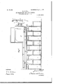
- Figure 1 is 5 a transverse section of a tunnel with such an apparatus embodying my improvements.
- Fig. 2 is a longitudinal section of the same, and
- Fig. 3 is an enlarged View of some details.
- a A are the me- 3 tallic segments which are fitted together to form the finished tubular lining of the tunnel
- B B are brackets which are bolted at a suitable height to the flanges of the segments of which the finished lining has been built up.
- This hydraulic erector comprises a foundation-plate 4, secured to the forward side of the traveling stage C and providing a bearing for a rotary plate 5, with pinion 6, into which gears a rack 7 on a piston-rod 8 with a piston working in the hydraulic cylinder 9,
- the means for attaching the segments to the outer end of the lifting-arm 10 may be those forming the subject of my Patent No. 7 80,804; but according to my present invention I reduce the required extent of rotary motion of the erecting-arm on the foundation-plate 4:, and at the same time I counterbalance the device better by making the arm 10 double-ended-that is, extending nearly across the tunnel so that as convenience may require a segment A to be put into place may be attached to either end of the arm or bar 10.
- brackets B B In order to facilitate the advance of the erecting-stage C as the lining is put in place, I provide on the brackets B B, on each side of the tunnel, two adjacent rails .D D, and the stage itself is provided on each side with wide wheels E E to rest on either rail or both rails.
- double-rail chairs F are provided on each bracket B, and while one rail D may be secured in the chair by means comparatively permanent the other rail D is secured in the chair by means which can be easily operated to drop the rail from supporting contact with the wheels, so that such rail can then be moved lengthwise.
- the wedges G G are withdrawn sufliciently to let the rails D D (on opposite sides of the tunnel) down out of supporting contact with the wheels E, so that said rails can then be shoved forward in the direction of the length of the tunnel as far as may be needed.
- the stage and movable rails D have been advanced sufficiently to permit of the introduction of other permanent rails D in front of those already in place, the stage may be run back temporarily to put the new rails in place, as will be readily understood.
- I provide the stage with a rail-gripping device, which is shown at R in Fig. 2 and is shown in detail in Fig. 3.
- a rail-gripping device which is shown at R in Fig. 2 and is shown in detail in Fig. 3.
- a side frame C of the stage I mount two cross-bolts h it, of which the latter is fixed, while the bolt it turns in bearings and has right and left hand threads engaging corresponding threads in clamping-jaws H H, which are also guided on the bolt h.
- the screw-bolt h is provided. with a hand-wheel if, by which it may be turned to advance the jaws H H toward each other to grip one of the rails or to move the jaws away from each other to free them from the rail.
- a segment-erector for tunnel-linings provided with a double-ended erector-bar and means to move it lengthwise and also to turn it on a central axis.
Landscapes
- Engineering & Computer Science (AREA)
- Mining & Mineral Resources (AREA)
- Environmental & Geological Engineering (AREA)
- Life Sciences & Earth Sciences (AREA)
- General Life Sciences & Earth Sciences (AREA)
- Geochemistry & Mineralogy (AREA)
- Geology (AREA)
- Lining And Supports For Tunnels (AREA)
Description
No. 794.635. PATENTED JULY 11, 1905. E. W. MOIR.
APPARATUS FOR ERBOTING TUNNELS.
APPLICATION FILED MAR. 18,- 1905.
3 SHEETS-SHEET 1.
INVENTOR M M 3r W W4 ATTORNEYS WITNESSES a My PATENTED JULY 11, 1905.
B. W. MOIR. APPARATUS FOR BREGTING TUNNELS.
APPLICATION FILED MAR. 18. 1905.
3 SHEBTS-SHEET 2.
INVENTOR WITNESSES I M M M fW/W ATTORNEYS No. 794.635. PATENTBD JULY 11, 1905. E. W. MOIR. APPARATUS FOR EREOTING TUNNELS.
APPLICATION FILED MAR.18, 1905.
3 SHEETS-SHEET B.
' INVENTOR ATTOR NEY$ wnNessEs UNITED STATES Patented July 11, 1905.
PATENT OFFICE.
ERNEST W. MOIR, OF LONDON, ENGLAND, ASSIGNOR TO S. PEARSON AND SON, INCORPORATED, OF LONG ISLAND CITY, NEW YORK, A CORPORA- TION OF NEW YORK.
APPARATUS FOR ERECTING TUNNELS- SPECIFICATION forming part of Letters Patent No. 794,635, dated July 11, 1905.
Application filed March 18, 1905. Serial No. 250,786.
To all whom it may concern:
Be it known that I, ERNEST W. M0111, a subject of the King of Great Britain and Ireland, residing in London, England, have invented 5 an Improved Apparatus for Erecting Tunnels,
of which the following is a specification.
My invention relates more particularly to the construction of apparatus for use in the building of tunnels, such as employed by me IO in the first Hudson river tunnel, as illustrated and described in the Journal of the London Society f Arts for May 15, 1896, Vol. XLIV, pages 567 and 584. Characteristic features of that apparatus were the construction of the lining of the tunnel of iron segments and the putting of these segments into place as the work progressed by means of a hydraulic erector mounted upon a stage traveling on rails which were carried by brackets secured to the erected tunnel-lining.
The main object of my present invention is to improve the construction and operation of such an erector apparatus.
In the accompanying drawings, Figure 1 is 5 a transverse section of a tunnel with such an apparatus embodying my improvements. Fig. 2 is a longitudinal section of the same, and Fig. 3 is an enlarged View of some details.
Referring to Figs. 1 and 2, A A are the me- 3 tallic segments which are fitted together to form the finished tubular lining of the tunnel, and B B are brackets which are bolted at a suitable height to the flanges of the segments of which the finished lining has been built up.
On these brackets are mounted rails D D, on which travel the wheels of the erector-stage C, carrying the hydraulic-erector mechanism intended to handle the segments to be put into place. This hydraulic erector comprises a foundation-plate 4, secured to the forward side of the traveling stage C and providing a bearing for a rotary plate 5, with pinion 6, into which gears a rack 7 on a piston-rod 8 with a piston working in the hydraulic cylinder 9,
mounted on the stage C. On the plate 5 there is mounted to slide in transverse guides a lift ing-arm or erector-bar 10, operated by a piston-rod 11, which is secured to the bar at 12 and which has a piston working in a hydraulic cylinder 13. The means for attaching the segments to the outer end of the lifting-arm 10 may be those forming the subject of my Patent No. 7 80,804; but according to my present invention I reduce the required extent of rotary motion of the erecting-arm on the foundation-plate 4:, and at the same time I counterbalance the device better by making the arm 10 double-ended-that is, extending nearly across the tunnel so that as convenience may require a segment A to be put into place may be attached to either end of the arm or bar 10.
In order to facilitate the advance of the erecting-stage C as the lining is put in place, I provide on the brackets B B, on each side of the tunnel, two adjacent rails .D D, and the stage itself is provided on each side with wide wheels E E to rest on either rail or both rails. As will be seen by reference to Fig. 3, double-rail chairs F are provided on each bracket B, and while one rail D may be secured in the chair by means comparatively permanent the other rail D is secured in the chair by means which can be easily operated to drop the rail from supporting contact with the wheels, so that such rail can then be moved lengthwise. In the drawings I have shown the chairs F as provided with wedges G, which can be driven into the chairs transversely under the rail D. Thus when the forward end of the traveling stage has to be advanced beyond the forward ends of what I may term the permanent railsD the wedges G G are withdrawn sufliciently to let the rails D D (on opposite sides of the tunnel) down out of supporting contact with the wheels E, so that said rails can then be shoved forward in the direction of the length of the tunnel as far as may be needed. When in the building of the tunnel the stage and movable rails D have been advanced sufficiently to permit of the introduction of other permanent rails D in front of those already in place, the stage may be run back temporarily to put the new rails in place, as will be readily understood.
As it is very important to secure exact location of the traveling stage in lifting the metallic lining-segments into place, I provide the stage with a rail-gripping device, which is shown at R in Fig. 2 and is shown in detail in Fig. 3. In a side frame C of the stage I mount two cross-bolts h it, of which the latter is fixed, while the bolt it turns in bearings and has right and left hand threads engaging corresponding threads in clamping-jaws H H, which are also guided on the bolt h. The screw-bolt h is provided. with a hand-wheel if, by which it may be turned to advance the jaws H H toward each other to grip one of the rails or to move the jaws away from each other to free them from the rail.
I claim as my invention 1. The combination of atunnel-lining, supporting-brackets therein and two sets of rails on the brackets with atraveling stage having wheels to run on both sets of rails.
2. The combination of a tunnel-lining, supporting-brackets therein and two sets of rails on the brackets with a traveling stage having wheels to run on both sets of rails and means for readily releasing one set of rails from their supporting position to permit their longitudinal adjustment.
3. The combination of a tunnel-lining, supporting-brackets therein and two sets of adjacent rails on the brackets with a traveling stage having at each side wide wheels to run on the two adjacent rails on that side.
4. The combination of a tunnel-lining, having supporting-brackets therein and two sets of rails on the brackets with a traveling stage having wheels to run on both sets of rails, chairs for the rails and easily-removed transverse wedges to support one set of rails in the chairs.
5. A segment-erector for tunnel-linings, provided with a double-ended erector-bar and means to move it lengthwise and also to turn it on a central axis.
6. The combination of a tunnel-lining and supporting-brackets therein with rails on the brackets, a traveling stage and a clamping devicle carried by the stage to grip one of the ra1 s.
In testimony whereofI have signed my name to this specification in the presence of two subscribing witnesses.
ERNEST W. MOIR. Witnesses:
(J. SEDGWICK, HUBERT HOWSON.
Priority Applications (1)
| Application Number | Priority Date | Filing Date | Title |
|---|---|---|---|
| US25078605A US794635A (en) | 1905-03-18 | 1905-03-18 | Apparatus for erecting tunnels. |
Applications Claiming Priority (1)
| Application Number | Priority Date | Filing Date | Title |
|---|---|---|---|
| US25078605A US794635A (en) | 1905-03-18 | 1905-03-18 | Apparatus for erecting tunnels. |
Publications (1)
| Publication Number | Publication Date |
|---|---|
| US794635A true US794635A (en) | 1905-07-11 |
Family
ID=2863123
Family Applications (1)
| Application Number | Title | Priority Date | Filing Date |
|---|---|---|---|
| US25078605A Expired - Lifetime US794635A (en) | 1905-03-18 | 1905-03-18 | Apparatus for erecting tunnels. |
Country Status (1)
| Country | Link |
|---|---|
| US (1) | US794635A (en) |
Cited By (3)
| Publication number | Priority date | Publication date | Assignee | Title |
|---|---|---|---|---|
| US3675433A (en) * | 1970-07-14 | 1972-07-11 | Sergei Nikolaevich Silvestrov | Device for constructing mines |
| US5116164A (en) * | 1989-10-26 | 1992-05-26 | Casagrande Spa | Device to load reinforcement rods |
| US20220307643A1 (en) * | 2021-03-26 | 2022-09-29 | Ballard Marine Construction, LLC | Carrier assembly systems, methods, and apparatus for repairing pipes in situ |
-
1905
- 1905-03-18 US US25078605A patent/US794635A/en not_active Expired - Lifetime
Cited By (4)
| Publication number | Priority date | Publication date | Assignee | Title |
|---|---|---|---|---|
| US3675433A (en) * | 1970-07-14 | 1972-07-11 | Sergei Nikolaevich Silvestrov | Device for constructing mines |
| US5116164A (en) * | 1989-10-26 | 1992-05-26 | Casagrande Spa | Device to load reinforcement rods |
| US20220307643A1 (en) * | 2021-03-26 | 2022-09-29 | Ballard Marine Construction, LLC | Carrier assembly systems, methods, and apparatus for repairing pipes in situ |
| US12055259B2 (en) * | 2021-03-26 | 2024-08-06 | Ballard Marine Construction, LLC | Carrier assembly systems, methods, and apparatus for repairing pipes in situ |
Similar Documents
| Publication | Publication Date | Title |
|---|---|---|
| EP0616077B1 (en) | Tamping machine for the compaction of railway ballast | |
| CN102720101B (en) | Line tamping stabilizing car and turnout stabilizing method | |
| JP2017530277A (en) | Orbital tamping machine for compression of track, ballast track bed | |
| CN108963882A (en) | A kind of cable straightening device that seabed uses | |
| AT403934B (en) | TAMPING UNIT FOR TRACKING MACHINES TO PLUG THREE THRESHOLD | |
| US794635A (en) | Apparatus for erecting tunnels. | |
| US1914899A (en) | Work clamp | |
| JPH0369703A (en) | Self-propelled track compacting machine with compacting equipment adjustable in transversal and vertical directions | |
| DE3409854A1 (en) | CONTINUOUSLY (NON-STOP) TRAVELABLE TRACK LEVELING AND LEVELING MACHINE | |
| US2727556A (en) | Straightening mechanism | |
| US1626948A (en) | Unloader for railroad cars | |
| DE1658736B2 (en) | Control device for a tunnel boring machine | |
| US709754A (en) | Metal-bending machine. | |
| US713894A (en) | Metal-bending machine | |
| US1109521A (en) | Machine for edging metal plates. | |
| DE3811875A1 (en) | Guide arrangement | |
| JP2005120746A5 (en) | ||
| US793433A (en) | Tamping-machine. | |
| US2696131A (en) | Vertical rolling mill | |
| ITMO960136A1 (en) | MACHINE FOR CUTTING BLOCKS OF GRANITE MARBLE AND STONES IN GENERAL WITH A MOBILE PORTAL AND RELATIVE PLANT | |
| US934088A (en) | Supporting mechanism for draw-cut shapers and analogous machines. | |
| US2605889A (en) | Feed for drawbenches or the like | |
| DE908305C (en) | Mechanism for measuring the wall thickness of pipe bodies | |
| DE632640C (en) | Electric arc welding device for large workpieces | |
| SU411265A1 (en) |